1
Motors I Automation I Energy I Transmission & Distribution I Coatings
Modbus RTU
CFW100
User’s Manual
Modbus RTU User’s Manual
Series: CFW100
Language: English
Document Number: 10002909455 / 01
Publication Date: 03/2015
Contents
CONTENTS
CONTENTS ......................................................................................................................... 3
ABOUT THIS MANUAL ...................................................................................................... 5
ABBREVIATIONS AND DEFINITIONS ......................................................................................................... 5
NUMERICAL REPRESENTATION ............................................................................................................... 5
DOCUMENTS................................................................................................................................................ 5
1
INTRODUCTION TO SERIAL COMMUNICATION ...................................................... 6
2
INTERFACE DESCRIPTION ......................................................................................... 7
2.1
RS485 COMMUNICATION MODULE (CFW100-CRS485) .............................................................. 7
2.1.1
RS485 module’s connector ....................................................................................................... 7
2.1.2
RS485 Interface Characteristics .............................................................................................. 7
2.1.3
Terminating resistor .................................................................................................................. 8
2.1.4
Indications .................................................................................................................................. 8
2.1.5
Connection with the RS485 Network ....................................................................................... 8
2.2
USB COMMUNICATION MODULE (CFW100-CUSB) ..................................................................... 8
2.2.1
Indications .................................................................................................................................. 8
3
PROGRAMMING .......................................................................................................... 9
3.1
SYMBOLS FOR THE PROPERTIES DESCRIPTION........................................................................ 9
P105 – 1ST/2ND RAMP SELECTION .............................................................................................................. 9
P220 – LOCAL/REMOTE SELECTION SOURCE ........................................................................................ 9
P221 – SPEED REFERENCE SELECTION – LOCAL SITUATION ............................................................. 9
P222 – SPEED REFERENCE SELECTION – REMOTE SITUATION .......................................................... 9
P223 – FORWARD/REVERSE SELECTION – LOCAL SITUATION ............................................................ 9
P224 – RUN/STOP SELECTION – LOCAL SITUATION.............................................................................. 9
P225 – JOG SELECTION – LOCAL SITUATION ......................................................................................... 9
P226 – FORWARD/REVERSE SELECTION – REMOTE SITUATION ........................................................ 9
P227 – RUN/STOP SELECTION – REMOTE SITUATION .......................................................................... 9
P228 – JOG SELECTION – REMOTE SITUATION ...................................................................................... 9
P308 – SERIAL ADDRESS............................................................................................................................ 9
P310 – SERIAL BAUD RATE ........................................................................................................................ 9
P311 – SERIAL INTERFACE BYTE CONFIGURATION ............................................................................ 10
P313 – COMMUNICATION ERROR ACTION ............................................................................................ 10
P314 – SERIAL WATCHDOG ..................................................................................................................... 11
P316 – SERIAL INTERFACE STATUS ....................................................................................................... 11
P680 – STATUS WORD .............................................................................................................................. 11
P681 – MOTOR SPEED IN 13 BITS ........................................................................................................... 12
P682 – SERIAL CONTROL WORD............................................................................................................. 13
P683 – SERIAL SPEED REFERENCE ........................................................................................................ 13
4
MODBUS RTU PROTOCOL ....................................................................................... 15
4.1
TRANSMISSION MODES ................................................................................................................ 15
4.2
MESSAGE STRUCTURE FOR RTU MODE .................................................................................... 15
4.2.1
Address ..................................................................................................................................... 15
4.2.2
Function Code .......................................................................................................................... 15
4.2.3
Data Field .................................................................................................................................. 15
4.2.4
CRC ........................................................................................................................................... 15
4.2.5
Time Between Messages ........................................................................................................ 15
5
OPERATION IN THE MODBUS RTU NETWORK – SLAVE MODE .......................... 17
CFW100 | 3
Contents
5.1
5.2
6
DETAILED DESCRIPTION OF THE FUNCTIONS ..................................................... 19
6.1
6.2
6.3
6.4
6.5
7
AVAILABLE FUNCTIONS AND RESPONSE TIMES ...................................................................... 17
MEMORY MAP................................................................................................................................. 17
FUNCTION 03 – READ HOLDING REGISTER ............................................................................... 19
FUNCTION 06 – WRITE SINGLE REGISTER ................................................................................. 19
FUNCTION 16 – WRITE MULTIPLE REGISTERS .......................................................................... 20
FUNCTION 43 – READ DEVICE IDENTIFICATION ........................................................................ 21
COMMUNICATION ERRORS.......................................................................................................... 21
FAULTS AND ALARMS RELATED TO THE MODBUS RTU COMMUNICATION .... 23
A128/F228 – TIMEOUT FOR SERIAL COMMUNICATION ....................................................................... 23
I.
APPENDICES ............................................................................................................. 24
APPENDIX A.
APPENDIX B.
ASCII TABLE .................................................................................................................... 24
CRC CALCULATION USING TABLES............................................................................ 25
CFW100 | 4
About this Manual
ABOUT THIS MANUAL
This manual supplies the necessary information for the operation of the CFW100 frequency inverter using the
Modbus RTU protocol. This manual must be used together with the CFW100 user manual.
ABBREVIATIONS AND DEFINITIONS
ASCII
CRC
EIA
TIA
RTU
American Standard Code for Information Interchange
Cycling Redundancy Check
Electronic Industries Alliance
Telecommunications Industry Association
Remote Terminal Unit
NUMERICAL REPRESENTATION
Decimal numbers are represented by means of digits without suffix. Hexadecimal numbers are represented with
the letter ‘h’ after the number. Binary numbers are represented with the letter ‘b’ after the number.
DOCUMENTS
The Modbus RTU protocol was developed based on the following specifications and documents:
Document
MODBUS Application Protocol Specification, December
28th 2006.
MODBUS Protocol Reference Guide, June 1996.
MODBUS over Serial Line, December 20th 2006.
Version
V1.1b
Source
MODBUS.ORG
Rev. J
V1.02
MODICON
MODBUS.ORG
In order to obtain this documentation, consult MODBUS.ORG, which is nowadays the organization that keeps,
publishes and updates the information related to the Modbus protocol.
CFW100 | 5
Introduction to Serial Communication
1 INTRODUCTION TO SERIAL COMMUNICATION
In a serial interface the data bits are sent sequentially through a communication channel or bus. Several
technologies use the serial communication for data transfer, including the RS232 and RS485 interfaces.
The directions that specify the RS232 and RS485 standards, however, do neither specify the character format,
nor its sequence for the data transmission and reception. Therefore, besides the interface, it is also necessary to
identify the protocol used for the communication. Among the several existent protocols, one used a lot in the
industry is the Modbus RTU protocol.
In the sequence the characteristics of the RS485 and USB serial interfaces available for the product will be
presented, as well as the Modbus RTU protocol for the use of this interface.
CFW100 | 6
Interface Description
2 INTERFACE DESCRIPTION
The interfaces for serial communication RS485 or USB available for the CFW100 frequency inverter depend on
the selected communication module for the product. Following are presented information about the connection
and installation of the equipment, using different communication modules.
2.1
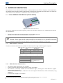
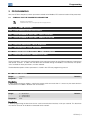
RS485 COMMUNICATION MODULE (CFW100-CRS485)
Figure 2.1: Module with RS485 interface
This plug-in module for the CFW100 frequency inverter has one RS485 interface. This standard RS485 interface
has two functions:
Point to Point Connection with remote keypad, via mini USB 1 connector.
Connection via RS485 for network operation, via terminals.
NOTE!
Although RS485 communication signal is available on both connectors – mini USB and control
terminal – these signals are the same (internally). For this reason, it is not possible to use RS485
interface as command source or reference source and remote keypad at the same time.
2.1.1
RS485 module’s connector
The RS485 interface connections are available via control terminal using the following pin assignment:
Table 2.1: RS485 connector pinout for the module (CFW100-CRS485)
Pin
6
7
8
Name
RS485 – B (-)
RS485 – A (+)
GND
Description
RxD/TxD negative
RxD/TxD positive
RS485 0V reference
Table 2.2: Configuration of the switches to configure the RS485
Switch Setting
S1.1 = OFF e S1.2 = OFF
S1.1 = ON e S1.2 = ON
S1.1 = OFF e S1.2 = ON
S1.1 = ON e S1.2 = OFF
S1.1 = ON e S1.2 = OFF
2.1.2
1
2
Option
RS485 Termination off
RS485 Termination on
This combination is not
allowed
RS485 Interface Characteristics
The interface follows the EIA/TIA-485 standard.
It allows communication baud rates from 9600 up to 38400 Kbit/s.
The interface is electrically isolated and with differential signal, which grants more robustness against
electromagnetic interference.
It allows the connection of up to 32 devices to the same segment. More devices can be connected by using
repeaters 2.
A maximum bus length of 1000 meters.
For connections that require distances greater than 3 meters, use remote keypad connection via control terminal.
The limit of devices that can be connected on the network depends on the protocol used.
CFW100 | 7
Interface Description
2.1.3
Terminating resistor
It is necessary to enable a terminating resistor at both ends of the main bus for each segment of the RS485
network. If the equipment located at both ends of the bus does not have termination resistors, use active
terminating to enable these resistors.
2.1.4
Indications
Details on the alarms, communications failures and communication states are made through the keypad (HMI)
and product parameters.
2.1.5
Connection with the RS485 Network
The following points must be observed for the connection of the device using the RS485 interface:
It is recommended the use of a shielded cable with a twisted pair of wires.
It is also recommended that the cable has one more wire for the connection of the reference signal (GND).
In case the cable does not have the additional wire, then the GND signal must be left disconnected.
The cable must be laid separately (and far away if possible) from the power cables.
All the network devices must be properly grounded, preferably at the same ground connection. The cable
shield must also be grounded.
Enable the termination resistors only at two points, at the extremes of the main bus, even if there are
derivations from the bus.
2.2
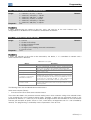
USB COMMUNICATION MODULE (CFW100-CUSB)
Figure 2.2: Module with USB connection
For this module, a USB interface with mini-USB conector is available. When connecting the USB interface, it will
be recognized as a USB to serial converter, and a virtual COM port will be created 3. Thus communication is
made with the drive via this COM port.
The USB accessory also provides the connection to the remote keypad via standard RS485 interface.
2.2.1
Indications
Details on the alarms, communications failures and communication states are made through the keypad (HMI)
and product parameters.
3
It is necessary to install the USB driver on the CD-ROM supplied with the product. The COM port number created depends on the
availability in the operating system and, once connected, consult the hardware resources of the system to identify this port. .
CFW100 | 8
Programming
3 PROGRAMMING
Next, the CFW100 frequency inverter parameters related to the Modbus RTU communication will be presented.
3.1
SYMBOLS FOR THE PROPERTIES DESCRIPTION
RO
CFG
Reading only parameter
Parameter that can be changed only with a stopped motor.
P105 – 1ST/2ND RAMP SELECTION
P220 – LOCAL/REMOTE SELECTION SOURCE
P221 – SPEED REFERENCE SELECTION – LOCAL SITUATION
P222 – SPEED REFERENCE SELECTION – REMOTE SITUATION
P223 – FORWARD/REVERSE SELECTION – LOCAL SITUATION
P224 – RUN/STOP SELECTION – LOCAL SITUATION
P225 – JOG SELECTION – LOCAL SITUATION
P226 – FORWARD/REVERSE SELECTION – REMOTE SITUATION
P227 – RUN/STOP SELECTION – REMOTE SITUATION
P228 – JOG SELECTION – REMOTE SITUATION
These parameters are used in the configuration of the command source for the CFW100 frequency inverter local
and remote situations. In order that the device be controlled through the Modbus RTU interface, the options
‘serial’ available in these parameters, must be selected.
The detailed description of these parameters is found in the CFW100 programming manual.
P308 – SERIAL ADDRESS
Range:
Properties:
1 to 247
CFG
Default: 1
Description:
It allows programming the address used for the inverter serial communication. It is necessary that each device in
the network has an address different from all the others.
P310 – SERIAL BAUD RATE
Range:
Properties:
0 = 9600 bits/s
1 = 19200 bits/s
2 = 38400 bits/s
CFG
Default: 0
Description:
It allows programming the baud rate for the serial communication interface, in bits per second. This baud rate
must be the same for all the devices connected to the network.
CFW100 | 9
Programming
P311 – SERIAL INTERFACE BYTE CONFIGURATION
Range:
Properties:
0 = 8 data bits, no parity, 1 stop bit
1 = 8 data bits, even parity, 1 stop bit
2 = 8 data bits, odd parity, 1 stop bit
3 = 8 data bits, no parity, 2 stop bits
4 = 8 data bits, even parity, 2 stop bits
5 = 8 data bits, odd parity, 2 stop bits
CFG
Default: 1
Description:
It allows programming the number of data bits, parity and stop bits of the serial interface bytes. This
configuration must be identical for all the devices connected to the network.
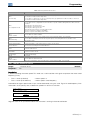
P313 – COMMUNICATION ERROR ACTION
Range:
Properties:
0 = Inactive
1 = Disable via Run/Stop
2 = Disable via General Enable
3 = Change to Local
4 = Change to Local keeping commands and reference
5 = Causes a Fault
CFG
Default: 1
Description:
It allows the selection of the action to be executed by the device, if it is controlled via network and a
communication error is detected.
Table 3.1: P313 options
Options
0 = Inactive
1 = Disable via Run/Stop
2 = Disable via General Enable
3 = Change to Local
4 = Change to Local keeping
commands and reference
5 = Causes a Fault
Description
No action is taken and the drive remains in the existing status.
A stop command with deceleration ramp is executed and the
motor stops according to the programmed deceleration ramp.
The drive is disabled by removing the General Enabling and the
motor coasts to stop.
The drive commands change to Local.
The drive commands change to Local, but the status of the
enabling and speed reference commands received via network
are kept, providing that the drive has been programmed to use in
Local mode the commands via HMI, or 3-wire start/stop and
speed reference via either HMI or electronic potentiometer.
Instead of an alarm, the communication error causes a drive fault,
so that a drive fault reset becomes necessary in order to restore
normal operation.
The following events are considered communication errors:
Serial communication (RS485):
A128 alarm/F228 fault: Serial communication timeout
The actions described in this parameter are executed by means of the automatic writing of the selected actions
in the respective bits of the interface control words. Therefore, in order that the commands written in this
parameter be effective, it is necessary that the device be programmed to be controlled via the used network
interface (with exception of option “Causes a Fault”, which blocks the equipment even if it is not controlled by
network). This programming is achieved by means of parameters P220 to P228.
CFW100 | 10
Programming
P314 – SERIAL WATCHDOG
Range:
Properties:
Default: 0.0
0.0 to 999.0s
CFG
Description:
It allows programming a time limit for the detection of serial interface communication error. If the frequency
inverter remains without receiving valid telegrams longer than the time programmed in this parameter, it will be
considered that a communication error has occurred, the alarm A128 will be showed on the HMI and the option
programmed in P313 will be executed.
After being powered up, the frequency inverter starts counting this time from the first received valid telegram.
The value 0.0 disables this function.
P316 – SERIAL INTERFACE STATUS
Range:
Default: -
0 = Inactive
1 = Active
2 = Watchdog error
RO
Properties:
Description:
It allows identifying whether the RS232 or RS485 serial interface board is properly installed, and whether the
serial communication presents errors.
Table 3.2: P316 options
Options
Description
Inactive serial interface. It occurs when the device does not have the RS232
or RS485 board installed
Installed and acknowledged RS232 or RS485 interface board.
The serial interface is active, but a serial communication error has been
detected - A128 alarm/F228 fault.
0 = Inactive
1 = Active
2 = Watchdog error
P680 – STATUS WORD
Range:
Properties:
Default: -
0000h to FFFFh
RO
Bits
15
14
13
12
11
10
9
8
7
6
5
4 to 0
Function
Fault condition
Reserved
Undervoltage
LOC/REM
JOG
Speed direction
Active General
Enable
Motor Running
Alarm condition
In configuration
mode
Second ramp
Reserved
Description:
It allows the device status monitoring. Each bit represents a specific status:
CFW100 | 11
Programming
Table 3.3: P680 parameter bit functions
Bits
Bits 0 to 4
Bit 5
Second ramp
Bit 6
In configuration mode
Bit 7
Alarm condition
Bit 8
Motor Running
Bit 9
Active General Enable
Bit 10
Speed direction
Bit 11
JOG
Bit 12
LOC/REM
Bit 13
Undervoltage
Bit 14
Bit 15
Fault condition
Values
Reserved.
0: The drive is configured to use the first ramp values, programmed in P100 and P101, as the motor
acceleration and deceleration ramp times.
1: The drive is configured to use the second ramp values, programmed in P102 and P103, as the motor
acceleration and deceleration ramp times.
0: The drive is operating normally.
1: The drive is in the configuration mode. It indicates a special condition during which the drive cannot be
enabled:
Executing the self-tuning routine
Executing the oriented start-up routine
Executing the HMI copy function
Executing the flash memory card self-guided routine
There is a parameter setting incompatibility
There is no power at the drive power section
0: The drive is not in alarm condition.
1: The drive is in alarm condition.
Note: The alarm number can be read by means of the parameter P048 – Present Alarm.
0: The motor is stopped.
1: The drive is running the motor at the set point speed, or executing either the acceleration or the
deceleration ramp.
0: General Enable is not active.
1: General Enable is active and the drive is ready to run the motor.
0: The motor is running in the reverse direction.
1: The motor is running in the forward direction.
0: Inactive JOG function.
1: Active JOG function.
0: Drive in Local mode.
1: Drive in Remote mode.
0: No Undervoltage.
1: With Undervoltage.
Reserved.
0: The drive is not in a fault condition.
1: The drive has detected a fault.
Note: The fault number can be read by means of the parameter P049 – Present Fault.
P681 – MOTOR SPEED IN 13 BITS
Range:
Properties:
Default: -
- 32768 to 32767
RO
Description:
It allows monitoring the motor speed. This word uses 13-bit resolution with signal to represent the motor rated
frequency (P403):
P681 = 0000h (0 decimal)
P681 = 2000h (8192 decimal)
→ motor speed = 0
→ motor speed = rated frequency
Intermediate or higher speed values in rpm can be obtained by using this scale. E.g.60Hz rated frequency if the
value read is 2048 (0800h), then, to obtain the speed in Hz one must calculate:
8192 => 60 Hz
2048 => Frequency in Hz
Frequency in Hz = 60 × 2048
8192
Frequency in Hz = 15 Hz
Negative values in this parameter indicate that the motor is running in the reverse direction.
CFW100 | 12
Programming
P682 – SERIAL CONTROL WORD
Range:
Properties:
Default: 0000h
0000h to FFFFh
-
Description:
It is the device Modbus RTU interface control word. This parameter can only be changed via serial interface. For
the other sources (HMI, etc.) it behaves like a read-only parameter.
In order to have those commands executed, it is necessary to program the equipment to be controlled via
serial. This programming is achieved by means of parameters P105 and P220 to P228.
6
5
4
3
2
1
0
Second ramp
LOC/REM
JOG
Speed direction
General enable
Run/Stop
Function
7
Reserved
15 to 8
Fault reset
Bits
Reserved
Each bit of this word represents a command that can be executed.
Table 3.4: P682 parameter bit functions
Bits
Bit 0
Run/Stop
Bit 1
General enable
Bit 2
Speed direction
Bit 3
JOG
Bit 4
LOC/REM
Bit 5
Second ramp
Bit 6
Bit 7
Fault reset
Bits 8 to 15
Values
0: It stops the motor with deceleration ramp.
1: The motor runs according to the acceleration ramp until reaching the speed reference value.
0: It disables the drive, interrupting the supply for the motor.
1: It enables the drive allowing the motor operation.
0: To run the motor in a direction opposed to the speed reference.
1: To run the motor in the direction indicated by the speed reference.
0: It disables the JOG function.
1: It enables the JOG function.
0: The drive goes to the Local mode.
1: The drive goes to the Remote mode.
0: The drive uses the first ramp values, programmed in P100 and P101, as the motor acceleration and
deceleration ramp times.
1: The drive is configured to use the second ramp values, programmed in P102 and P103, as the
motor acceleration and deceleration ramp times.
Reserved.
0: No function.
1: If in a fault condition, then it executes the reset.
Reserved.
P683 – SERIAL SPEED REFERENCE
Range:
Properties:
Default: 0
-32768 to 32767
-
Description:
It allows programming the motor speed reference via the Modbus RTU interface. This parameter can only be
changed via serial interface. For the other sources (HMI, etc.) it behaves like a read-only parameter.
In order that the reference written in this parameter be used, it is necessary that the drive be programmed to
use the speed reference via serial. This programming is achieved by means of parameters P221 and P222.
This word uses a 13-bit resolution with signal to represent the motor rated frequency (P403).
P683 = 0000h (0 decimal)
P683 = 2000h (8192 decimal)
→ speed reference = 0
→ speed reference = rated frequency (P403)
Intermediate or higher reference values can be programmed by using this scale. E.g.60Hz rated frequency, to
obtain a speed reference of 30 Hz one must calculate:
CFW100 | 13
Programming
60 Hz => 8192
30 Hz => 13 bit reference
13 bit reference = 30 × 8192
60
13 bit reference = 4096
=> Value corresponding to 30 Hz in a 13 bit scale
This parameter also accepts negative values to revert the motor speed direction. The reference speed direction,
however, depends also on the control word - P682 - bit 2 setting:
Bit 2 = 1 and P683 > 0: reference for forward direction
Bit 2 = 1 and P683 < 0: reference for reverse direction
Bit 2 = 0 and P683 > 0: reference for reverse direction
Bit 2 = 0 and P683 < 0: reference for forward direction
CFW100 | 14
Modbus RTU Protocol
4 MODBUS RTU PROTOCOL
The Modbus RTU protocol was initially developed in 1979. Nowadays, it is a widely spread open protocol, used
by several manufactures in many equipments.
4.1
TRANSMISSION MODES
Two transmission modes are defined in the protocol specification: ASCII and RTU. The modes define the way
the message bytes are transmitted. It is not possible to use the two transmission modes in the same network.
The CFW100 frequency inverter uses only the RTU mode for the telegram transmission. The bytes are
transmitted in hexadecimal format and its configuration depends on the programming done by means of P311.
4.2
MESSAGE STRUCTURE FOR RTU MODE
The Modbus RTU structure uses a master-slave system for message exchange. It allows up to 247 slaves, but
only one master. Every communication begins with the master making a request to a slave, which answers to
the master what has been asked. In both telegrams (request and answer), the used structure is the same:
Address, Function Code, Data and CRC. Only the data field can have a variable size, depending on what is
being requested.
Master (request telegram):
Address
(1 byte)
Function
(1 byte)
Request Data
(n bytes)
CRC
(2 bytes)
Function
(1 byte)
Response Data
(n bytes)
CRC
(2 bytes)
Slave (response telegram):
Address
(1 byte)
4.2.1
Address
The master initiates the communication sending a byte with the address of the slave to which the message is
destined. When sending the answer, the slave also initiates the telegram with its own address. The master can
also send a message to the address 0 (zero), which means that the message is destined to all the slaves in the
network (broadcast). In that case, no slave will answer to the master.
4.2.2
Function Code
This field also contains a single byte, where the master specifies the kind of service or function requested to the
slave (reading, writing, etc.). According to the protocol, each function is used to access a specific type of data.
For the available list of supported functions, refer to item 5.
4.2.3
Data Field
It is a variable size field. The format and contents of this field depend on the used function and the transmitted
value. This field is described together with the function description (refer to item 5).
4.2.4
CRC
The last part of the telegram is the field for checking the transmission errors. The used method is the CRC-16
(Cycling Redundancy Check). This field is formed by two bytes; where first the least significant byte is
transmitted (CRC-), and then the most significant (CRC+). The CRC calculation form is described in the protocol
specification; however, information for its implementation is also supplied in the Appendix B.
4.2.5
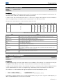
Time Between Messages
In the RTU mode there is no specific character that indicates the beginning or the end of a telegram. The
indication of when a new message begins or when it ends is done by the absence of data transmission in the
network, for a minimum period of 3.5 times the transmission time of a data byte (11 bits). Thus, in case a
telegram has initiated after the elapsing of this minimum time, the network elements will assume that the first
CFW100 | 15
Modbus RTU Protocol
received character represents the beginning of a new telegram. And in the same manner, the network elements
will assume that the telegram has reached its end when after receiving the telegram elements, this time has
elapsed again.
If during the transmission of a telegram the time between the bytes is longer than this minimum time, the
telegram will be considered invalid because the frequency inverter will discard the bytes already received and
will mount a new telegram with the bytes that were being transmitted.
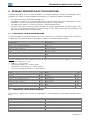
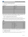
For communication rates higher than 19200 bits/s, the used times are the same as for that rate. The next table
shows us the times for different communication transmission rates:
Table 4.1: Communication rates and the time periods involved in the telegram transmission
Baud rate
1200 bits/s
2400 bits/s
4800 bits/s
9600 bits/s
19200 bits/s
38400 bits/s
57600 bits/s
T11 bits
9.167 ms
4.583 ms
2.292 ms
1.146 ms
573 µs
573 µs
573 µs
T3,5x
32.083 ms
16.042 ms
8.021 ms
4.010 ms
2.005 ms
2.005 ms
2.005 ms
= Time for transmitting one byte of the telegram.
T11 bits
Tbetween bytes = Time between bytes.
= Minimum interval to indicated beginning and end of a telegram (3.5 x T11bits).
T3,5x
CFW100 | 16
Operation in the Modbus RTU Network – Slave Mode
5 OPERATION IN THE MODBUS RTU NETWORK – SLAVE MODE
The CFW100 frequency inverter has the following characteristics when operated in Modbus RTU network:
5.1
Network connection via RS485 serial interface.
Address, communication rate and byte format defined by means of parameters.
It allows the device programming and control via the access to parameters.
AVAILABLE FUNCTIONS AND RESPONSE TIMES
In the Modbus RTU specification are defined the functions used to access different types of data. In the
CFW100 the parameters have been defined as being holding type registers. In order to access those data the
following services (or functions) have been made available:
Read Holding Registers
Description: reading of register blocks of the holding register type.
Function code: 03.
Read Input Registers
Description: reading of register blocks of the input register type.
Function code: 04.
Write Single Register
Description: writing in a single register of the holding type.
Function code: 06.
Write Multiple Registers
Description: writing in register blocks of the holding register type.
Function code: 16.
Read Device Identification
Description: identification of the device model.
Function code: 43.
The response time, from the end of transmission of the master until the response of the slave, ranges from 2 to
10 ms for any of the functions above.
5.2
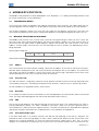
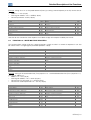
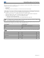
MEMORY MAP
The CFW100 Modbus communication is based on the reading/writing of the equipment parameters. All the
drive parameters list is made available as holding type 16-bit registers. The data addressing is done with the
offset equal to zero, which means that the parameter number corresponds to the register address. The
following table illustrates the parameters addressing, which can be accessed as holding type register.
Table 5.1: Modbus RTU Memory Map
Parameter number
P000
P001
Modbus data address
Decimal
Hexadecimal
0
0000h
1
0001h
...
...
...
P100
100
0064h
...
...
...
It is necessary to know the inverter list of parameters to be able to operate the equipment. Thus, it is possible to
identify what data are needed for the status monitoring and the control of the functions. The main parameters
are:
Monitoring (reading):
CFW100 | 17
Operation in the Modbus RTU Network – Slave Mode
P680: Status word
P681: Motor speed
Command (writing):
P682: Command Word
P683: Speed Reference
Refer to the Programming Manual for a complete parameter list of the equipment.
NOTE!
All the parameters are treated as holding type registers. Depending on the master that is used,
those registers are referenced starting from the base address 40000 or 4x. In this case, the
address that must be programmed in the master for a parameter is the address showed in the
table above added to the base address. Refer to the master documentation to find out how to
access holding type registers.
It should be noted that read-only parameters can only be read from the equipment, while other
parameters can be read and written through the network.
CFW100 | 18
Detailed Description of the Functions
6 DETAILED DESCRIPTION OF THE FUNCTIONS
A detailed description of the functions available in the CFW100 frequency inverter for the Modbus RTU is
provided in this section. In order to elaborate the telegrams it is important to observe the following:
The values are always transmitted in hexadecimal.
The address of a datum, the number of data and the value of registers are always represented in 16 bits.
Therefore, it is necessary to transmit those fields using two bytes – high and low.
The telegrams for request, as well as for response, cannot exceed 64 bytes.
The transmitted values are always integer, regardless of having a representation with decimal point. Thus,
the value 9.5 would be transmitted via serial as being 95 (5Fh). Refer to the CFW100 parameter list to
obtain the resolution used for each parameter.
6.1
FUNCTION 03 – READ HOLDING REGISTER
It reads the content of a group of registers that must be necessarily in a numerical sequence. This function has
the following structure for the request and response telegrams (each field represents a byte):
Request (Master)
Slave Address
Function
Address of the initial register (high byte)
Address of the initial register (low byte)
Number of registers (high byte)
Number of registers (low byte)
CRCCRC+
Response (Slave)
Slave Address
Function
Byte count
Datum 1 (high byte)
Datum 1 (low byte)
Datum 2 (high byte)
Datum 2 (low byte)
etc...
CRCCRC+
Example: reading of the motor speed (P002) and the motor current (P003) of slave at address 1 (assuming that
P002 = 30 Hz and P003 = 1.5 A).
Address: 1 = 01h (1 byte)
Initial register address: 2 = 0002h (2 bytes)
Value of the first parameter: 30 = 001Eh (2 bytes)
Value of the second parameter: 15 = 000Fh (2 bytes)
Request (Master)
Response (Slave)
Field
Value
Field
Value
Slave Address
Function
Address of the initial register (high byte)
Address of the initial register (low byte)
Number of registers (high byte)
Number of registers (low byte)
CRCCRC+
01h
03h
00h
02h
00h
02h
65h
CBh
Slave Address
Function
Byte count
P002 (high byte)
P002 (low byte)
P003 (high byte)
P003 (low byte)
CRCCRC+
01h
03h
04h
00h
1Eh
00h
0Fh
DAh
31h
6.2
FUNCTION 06 – WRITE SINGLE REGISTER
This function is used to write a value for a single register. It has the following structure (each field represents a
byte):
Request (Master)
Slave Address
Function
Register address (high byte)
Register address (low byte)
Value for the register (high byte)
Value for the register (low byte)
CRCCRC+
Response (Slave)
Slave Address
Function
Register address (high byte)
Register address (low byte)
Value for the register (high byte)
Value for the register (low byte)
CRCCRC+
CFW100 | 19
Detailed Description of the Functions
Example: writing of 30 Hz as the speed reference (P683) (assuming a motor frequency of 60 Hz) for the slave at
address 3.
Address: 3 = 03h (1 byte)
Initial register address: 683 = 02ABh (2 bytes)
Value for parameter: 1000h (2 bytes)
Request (Master)
Response (Slave)
Field
Value
Field
Value
Slave Address
Function
Register address (high byte)
Register address (low byte)
Value (high byte)
Value (low byte)
CRCCRC+
03h
06h
02h
ABh
10h
00h
F5h
B0h
Slave Address
Function
Register address (high byte)
Register address (low byte)
Value (high byte)
Value (low byte)
CRCCRC+
03h
06h
02h
ABh
10h
00h
F5h
B0h
Note that for this function the slave response is an identical copy of the request made by the master.
6.3
FUNCTION 16 – WRITE MULTIPLE REGISTERS
This function allows writing values for a group of registers, which must be in a numerical sequence. It can also
be used to write in a single register (each field represents a byte):
Request (Master)
Slave Address
Function
Initial register address (high byte)
Initial register address (low byte)
Number of registers (high byte)
Number of registers (low byte)
Byte count (number of data bytes)
Datum 1 (high byte)
Datum 1 (low byte)
Datum 2 (high byte)
Datum 2 (low byte)
etc...
CRCCRC+
Response (Slave)
Slave Address
Function
Initial register address (high byte)
Initial register address (low byte)
Number of registers (high byte)
Number of registers (low byte)
CRCCRC+
Example: writing of the acceleration time (P100) equal to 1.0 s and the deceleration time (P101) equal to 2.0 s,
of a slave at address 15.
Address: 15 = 0Fh (1 byte)
Initial register address: 100 = 0064h (2 bytes)
Value for the first parameter: 10 = 000Ah (2 bytes)
Value for the second parameter: 20 = 0014h (2 bytes)
Request (Master)
Field
Slave Address
Function
Initial register address (high byte)
Initial register address (low byte)
Number of registers (high byte)
Number of registers (low byte)
Byte count
P100 (high byte)
P100 (low byte)
P101 (high byte)
P101 (low byte)
CRCCRC+
Response (Slave)
Value
0Fh
10h
00h
64h
00h
02h
04h
00h
0Ah
00h
14h
E0h
91h
Field
Slave Address
Function
Initial register address (high byte)
Initial register address (low byte)
Number of registers (high byte)
Number of registers (low byte)
CRCCRC+
Value
0Fh
10h
00h
64h
00h
02h
01h
39h
CFW100 | 20
Detailed Description of the Functions
6.4
FUNCTION 43 – READ DEVICE IDENTIFICATION
It is an auxiliary function that allows the reading of the product manufacturer, model and firmware version. It has
the following structure:
Request (Master)
Slave Address
Function
MEI Type
Reading code
Object number
CRCCRC+
Response (Slave)
Slave Address
Function
MEI Type
Conformity Level
More Follows
Next object
Number of objects
Code of the first object
Size of the first object
Value of the first object (n bytes)
Code of the second object
Size of the second object
Value of the second object (n bytes)
etc...
CRCCRC+
This function allows the reading of three information categories: Basic, Regular and Extended, and each
category is formed by a group of objects. Each object is formed by a sequence of ASCII characters. For the
CFW100 frequency inverter, only basic information formed by three objects is available:
Objeto 00h – VendorName: represents the product manufacturer.
Objeto 01h – ProductCode: formed by the product code (CFW100).
Objeto 02h – MajorMinorRevision: it indicates the product firmware version, in the format ‘VX.XX’.
The reading code indicates what information categories are read, and if the objects are accessed in sequence
or individually. The CFW100 supports the codes 01 (basic information in sequence) and 04 (individual access to
the objects). The other fields are specified by the protocol, and for the CFW100 they have fixed values.
Example: reading of basic information in sequence, starting from the object 02h, from a CFW100 at address 1:
Request (Master)
Field
Response (Slave)
Value
Slave Address
Function
MEI Type
Reading code
Object number
CRCCRC+
01h
2Bh
0Eh
01h
02h
70h
77h
Field
Slave Address
Function
MEI Type
Reading code
Conformity Level
More Follows
Next object
Number of objects
Object code
Object size
Object value
CRCCRC+
Value
01h
2Bh
0Eh
01h
81h
00h
00h
01h
02h
05h
'V1.00'
3Ch
53h
In this example the value of the objects was not represented in hexadecimal, but using the corresponding ASCII
characters instead. E.g.: for the object 02h, the value ‘V1.00’ was transmitted as being five ASCII characters,
which in hexadecimal have the values 56h ('V'), 31h ('1'), 2Eh ('.'), 30h ('0') and 30h ('0').
6.5
COMMUNICATION ERRORS
Communication errors may occur in the transmission of telegrams, as well as in the contents of the transmitted
telegrams. Depending on the type of error, the slave may or not send a response to the master.
CFW100 | 21
Detailed Description of the Functions
When the master sends a message for an inverter configured in a specific network address, the product will not
respond to the master if the following occurs:
Parity bit error.
CRC error.
Timeout between the transmitted bytes (3.5 times the transmission time of a byte).
In those cases, the master must detect the occurrence of the error by means of the timeout while waiting for the
slave response. In the event of a successful reception, during the treatment of the telegram, the slave may
detect problems and send an error message, indicating the kind of problem found:
Invalid function (Error code = 1): The requested function has not been implemented for the equipment.
Invalid datum address (Error code = 2): the datum address does not exist.
Invalid datum value (Error code = 3): It occurs in the following situations:
The value is out of the permitted range.
An attempt to write in a datum that cannot be changed (reading only register/bit).
NOTE!
It is important that it be possible to identify at the master what type of error occurred, in order to be
able to diagnose problems during the communication.
In the event of any of those errors, the slave must send a message to the master indicating the type of error that
occurred. The error messages sent by the slave have the following structure:
Request (Master)
Slave Address
Function
Data
CRCCRC+
Response (Slave)
Slave Address
Function (with the most significant bit in 1)
Error code
CRCCRC+
Example: the master requests to the slave at the address 1 the writing in the register 2900 (nonexistent register):
Request (Master)
Response (Slave)
Field
Value
Field
Value
Slave Address
Function
Register address (high byte)
Register address (low byte)
Value (high byte)
Value (low byte)
CRCCRC+
01h
06h
0Bh
54h
00h
00h
CAh
3Eh
Slave Address
Function
Error code
CRCCRC+
01h
86h
02h
C3h
A1h
CFW100 | 22
Faults and Alarms Related to the Modbus RTU Communication
7 FAULTS AND ALARMS RELATED TO THE MODBUS RTU
COMMUNICATION
A128/F228 – TIMEOUT FOR SERIAL COMMUNICATION
Description:
It is the only alarm/fault related to the serial communication indicates that the equipment stopped receiving valid
serial telegrams for a period longer than the one programmed in P314.
Operation:
The parameter P314 allows programming a period of time during which the equipment must receive at least one
valid telegram via the RS485 serial interface – with address and error-checking field correct – otherwise, it will
be considered that there was any problem in the serial communication. The time counting initiates after the
reception of the first valid telegram. This function can be used by any serial protocol supported by the
equipment.
After the serial communication timeout has been identified, the A128 alarm or F228 fault message will be
showed on the HMI, depending on the P313 programming. For alarms, if the communication is reestablished
and new valid telegrams are received, the alarm indication will be removed from the HMI.
Possible Causes/Correction:
Verify factors that could cause failures in the communication (cables, installation, and grounding).
Make sure that the master sends telegrams to the equipment in intervals shorter than the programmed in
P314.
Disable this function at P314.
CFW100 | 23
Appendices
I. APPENDICES
APPENDIX A. ASCII TABLE
Table I.1: ASCII Characters
Dec
0
1
2
3
4
5
6
7
8
9
10
11
12
13
14
15
16
17
18
19
20
21
22
23
24
25
26
27
28
29
30
31
Hex
00
01
02
03
04
05
06
07
08
09
0A
0B
0C
0D
0E
0F
10
11
12
13
14
15
16
17
18
19
1A
1B
1C
1D
1E
1F
Chr
NUL
SOH
STX
ETX
EOT
ENQ
ACK
BEL
BS
HT
LF
VT
FF
CR
SO
SI
DLE
DC1
DC2
DC3
DC4
NAK
SYN
ETB
CAN
EM
SUB
ESC
FS
GS
RS
US
(Null char.)
(Start of Header)
(Start of Text)
(End of Text)
(End of Transmission)
(Enquiry)
(Acknowledgment)
(Bell)
(Backspace)
(Horizontal Tab)
(Line Feed)
(Vertical Tab)
(Form Feed)
(Carriage Return)
(Shift Out)
(Shift In)
(Data Link Escape)
(Device Control 1)
(Device Control 2)
(Device Control 3)
(Device Control 4)
(Negative Acknowledgement)
(Synchronous Idle)
(End of Trans. Block)
(Cancel)
(End of Medium)
(Substitute)
(Escape)
(File Separator)
(Group Separator)
(Record Separator)
(Unit Separator)
Dec
32
33
34
35
36
37
38
39
40
41
42
43
44
45
46
47
48
49
50
51
52
53
54
55
56
57
58
59
60
61
62
63
Hex
20
21
22
23
24
25
26
27
28
29
2A
2B
2C
2D
2E
2F
30
31
32
33
34
35
36
37
38
39
3A
3B
3C
3D
3E
3F
Chr
Sp
!
"
#
$
%
&
'
(
)
*
+
,
.
/
0
1
2
3
4
5
6
7
8
9
:
;
<
=
>
?
Dec
64
65
66
67
68
69
70
71
72
73
74
75
76
77
78
79
80
81
82
83
84
85
86
87
88
89
90
91
92
93
94
95
Hex
40
41
42
43
44
45
46
47
48
49
4A
4B
4C
4D
4E
4F
50
51
52
53
54
55
56
57
58
59
5A
5B
5C
5D
5E
5F
Chr
@
A
B
C
D
E
F
G
H
I
J
K
L
M
N
O
P
Q
R
S
T
U
V
W
X
Y
Z
[
\
]
^
_
Dec
96
97
98
99
100
101
102
103
104
105
106
107
108
109
110
111
112
113
114
115
116
117
118
119
120
121
122
123
124
125
126
127
Hex
60
61
62
63
64
65
66
67
68
69
6A
6B
6C
6D
6E
6F
70
71
72
73
74
75
76
77
78
79
7A
7B
7C
7D
7E
7F
Chr
`
a
b
c
d
e
f
g
h
i
j
k
l
m
n
o
p
q
r
s
t
u
v
w
x
y
z
{
|
}
~
DEL
CFW100 | 24
Appendices
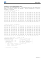
APPENDIX B. CRC CALCULATION USING TABLES
Next, a function using programming language “C” is presented, which implements the CRC calculation for the
Modbus RTU protocol. The calculation uses two tables to supply pre-calculated values of the necessary
displacement for the calculation.
/* Table of CRC values for high–order byte */
static unsigned char auchCRCHi[] = {
0x00, 0xC1, 0x81, 0x40, 0x01, 0xC0, 0x80, 0x41, 0x01, 0xC0, 0x80, 0x41, 0x00, 0xC1, 0x81,
0x01, 0xC0, 0x80, 0x41, 0x00, 0xC1, 0x81, 0x40, 0x00, 0xC1, 0x81, 0x40, 0x01, 0xC0, 0x80,
0x01, 0xC0, 0x80, 0x41, 0x00, 0xC1, 0x81, 0x40, 0x00, 0xC1, 0x81, 0x40, 0x01, 0xC0, 0x80,
0x00, 0xC1, 0x81, 0x40, 0x01, 0xC0, 0x80, 0x41, 0x01, 0xC0, 0x80, 0x41, 0x00, 0xC1, 0x81,
0x01, 0xC0, 0x80, 0x41, 0x00, 0xC1, 0x81, 0x40, 0x00, 0xC1, 0x81, 0x40, 0x01, 0xC0, 0x80,
0x00, 0xC1, 0x81, 0x40, 0x01, 0xC0, 0x80, 0x41, 0x01, 0xC0, 0x80, 0x41, 0x00, 0xC1, 0x81,
0x00, 0xC1, 0x81, 0x40, 0x01, 0xC0, 0x80, 0x41, 0x01, 0xC0, 0x80, 0x41, 0x00, 0xC1, 0x81,
0x01, 0xC0, 0x80, 0x41, 0x00, 0xC1, 0x81, 0x40, 0x00, 0xC1, 0x81, 0x40, 0x01, 0xC0, 0x80,
0x01, 0xC0, 0x80, 0x41, 0x00, 0xC1, 0x81, 0x40, 0x00, 0xC1, 0x81, 0x40, 0x01, 0xC0, 0x80,
0x00, 0xC1, 0x81, 0x40, 0x01, 0xC0, 0x80, 0x41, 0x01, 0xC0, 0x80, 0x41, 0x00, 0xC1, 0x81,
0x00, 0xC1, 0x81, 0x40, 0x01, 0xC0, 0x80, 0x41, 0x01, 0xC0, 0x80, 0x41, 0x00, 0xC1, 0x81,
0x01, 0xC0, 0x80, 0x41, 0x00, 0xC1, 0x81, 0x40, 0x00, 0xC1, 0x81, 0x40, 0x01, 0xC0, 0x80,
0x00, 0xC1, 0x81, 0x40, 0x01, 0xC0, 0x80, 0x41, 0x01, 0xC0, 0x80, 0x41, 0x00, 0xC1, 0x81,
0x01, 0xC0, 0x80, 0x41, 0x00, 0xC1, 0x81, 0x40, 0x00, 0xC1, 0x81, 0x40, 0x01, 0xC0, 0x80,
0x01, 0xC0, 0x80, 0x41, 0x00, 0xC1, 0x81, 0x40, 0x00, 0xC1, 0x81, 0x40, 0x01, 0xC0, 0x80,
0x00, 0xC1, 0x81, 0x40, 0x01, 0xC0, 0x80, 0x41, 0x01, 0xC0, 0x80, 0x41, 0x00, 0xC1, 0x81, 0x40
0x40,
0x41,
0x41,
0x40,
0x41,
0x40,
0x40,
0x41,
0x41,
0x40,
0x40,
0x41,
0x40,
0x41,
0x41,
};
/* Table of
static char
0x00, 0xC0,
0xCC, 0x0C,
0xD8, 0x18,
0x14, 0xD4,
0xF0, 0x30,
0x3C, 0xFC,
0x28, 0xE8,
0xE4, 0x24,
0xA0, 0x60,
0x6C, 0xAC,
0x78, 0xB8,
0xB4, 0x74,
0x50, 0x90,
0x9C, 0x5C,
0x88, 0x48,
0x44, 0x84,
0x04,
0xC8,
0xDC,
0x10,
0xF4,
0x38,
0x2C,
0xE0,
0xA4,
0x68,
0x7C,
0xB0,
0x54,
0x98,
0x8C,
};
CRC values for low–order byte */
auchCRCLo[] = {
0xC1, 0x01, 0xC3, 0x03, 0x02, 0xC2, 0xC6, 0x06, 0x07, 0xC7, 0x05, 0xC5, 0xC4,
0x0D, 0xCD, 0x0F, 0xCF, 0xCE, 0x0E, 0x0A, 0xCA, 0xCB, 0x0B, 0xC9, 0x09, 0x08,
0x19, 0xD9, 0x1B, 0xDB, 0xDA, 0x1A, 0x1E, 0xDE, 0xDF, 0x1F, 0xDD, 0x1D, 0x1C,
0xD5, 0x15, 0xD7, 0x17, 0x16, 0xD6, 0xD2, 0x12, 0x13, 0xD3, 0x11, 0xD1, 0xD0,
0x31, 0xF1, 0x33, 0xF3, 0xF2, 0x32, 0x36, 0xF6, 0xF7, 0x37, 0xF5, 0x35, 0x34,
0xFD, 0x3D, 0xFF, 0x3F, 0x3E, 0xFE, 0xFA, 0x3A, 0x3B, 0xFB, 0x39, 0xF9, 0xF8,
0xE9, 0x29, 0xEB, 0x2B, 0x2A, 0xEA, 0xEE, 0x2E, 0x2F, 0xEF, 0x2D, 0xED, 0xEC,
0x25, 0xE5, 0x27, 0xE7, 0xE6, 0x26, 0x22, 0xE2, 0xE3, 0x23, 0xE1, 0x21, 0x20,
0x61, 0xA1, 0x63, 0xA3, 0xA2, 0x62, 0x66, 0xA6, 0xA7, 0x67, 0xA5, 0x65, 0x64,
0xAD, 0x6D, 0xAF, 0x6F, 0x6E, 0xAE, 0xAA, 0x6A, 0x6B, 0xAB, 0x69, 0xA9, 0xA8,
0xB9, 0x79, 0xBB, 0x7B, 0x7A, 0xBA, 0xBE, 0x7E, 0x7F, 0xBF, 0x7D, 0xBD, 0xBC,
0x75, 0xB5, 0x77, 0xB7, 0xB6, 0x76, 0x72, 0xB2, 0xB3, 0x73, 0xB1, 0x71, 0x70,
0x91, 0x51, 0x93, 0x53, 0x52, 0x92, 0x96, 0x56, 0x57, 0x97, 0x55, 0x95, 0x94,
0x5D, 0x9D, 0x5F, 0x9F, 0x9E, 0x5E, 0x5A, 0x9A, 0x9B, 0x5B, 0x99, 0x59, 0x58,
0x49, 0x89, 0x4B, 0x8B, 0x8A, 0x4A, 0x4E, 0x8E, 0x8F, 0x4F, 0x8D, 0x4D, 0x4C,
0x85, 0x45, 0x87, 0x47, 0x46, 0x86, 0x82, 0x42, 0x43, 0x83, 0x41, 0x81, 0x80, 0x40
/* The function returns the CRC as a unsigned short type */
unsigned short CRC16(puchMsg, usDataLen)
unsigned char *puchMsg;
/* message to calculate CRC upon
unsigned short usDataLen;
/* quantity of bytes in message
{
unsigned char uchCRCHi = 0xFF;
/* high byte of CRC initialized
unsigned char uchCRCLo = 0xFF;
/* low byte of CRC initialized
unsigned uIndex;
/* will index into CRC lookup table
while (usDataLen--)
/* pass through message buffer
{
uIndex = uchCRCLo ^ *puchMsgg++; /* calculate the CRC
uchCRCLo = uchCRCHi ^ auchCRCHi[uIndex];
uchCRCHi = auchCRCLo[uIndex];
}
*/
*/
*/
*/
*/
*/
*/
return (uchCRCHi << 8 | uchCRCLo);
}
CFW100 | 25
WEG Drives & Controls - Automação LTDA.
Jaraguá do Sul – SC – Brazil
Phone 55 (47) 3276-4000 – Fax 55 (47) 3276-4020
São Paulo – SP – Brazil
Phone 55 (11) 5053-2300 – Fax 55 (11) 5052-4212
[email protected]
www.weg.net