Transcript
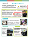
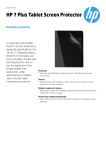
Aquarian Hydrophone System output jack replacement:
Your Aquarian system offers the unique feature of having a user-replaceable output jack. Seawater is
quite corrosive to electrical contacts. Having this feature allows you to very easily and inexpensively
repair your system should you encounter problems related to a buildup of corrosion that ultimately
interferes with the system’s output.
With the yellow battery/amplifier cover removed, you’ll see the jumper wires connecting the output jack
to the power amplifier board. Note how these wires are positioned into the amplifier, then pull each out
of its receptacle and straiten the jumper wires out so that the output jack can be twisted out of the black
casting. Simply unscrew the existing jack from the casting in a standard counter-clockwise direction (from
the perspective of looking into the hole of the jack). A small pair of pliers will be needed to grip the
output jack during removal and replacement. Install the new jack in the reverse order of removing it.
Finish by plugging the jumper wires into the amplifier as it was with the old jack installment. For details
on output jack jumper placement in the amplifier board, see: Output Jack Configuration in your user’s
manual. Tweezers or a small pair of needle-nosed pliers will be helpful during wire removal and insertion.
Also note that the output header on the amplifier board is color-coded.
If you have any questions or problems with this procedure, please contact Aquarian Audio technical
support in the United States at: 360-299-0372, or [email protected].
Thank you!
Does this output jack look different than your existing one?
The Aquarian Hydrophone System’s headphone amplifier and output jack configuration changed to its
current state in August of 2002. If you bought your system near to this date or before, you will notice a
difference between this jack and your existing one.
Note that the output header (where the jack plug in) has a white marker on one end with five spaces for
wire insertion. If we assign the insertion space next to the white marker as insertion point 1 (IP1), and
number them sequentially to the furthest insertion point (IP5), then wire insertion of the new jack is as
follows:
Output configuration
Single-ended stereo (standard)
Single-ended mono *
BTL mono
IP1
IP2
IP3
IP4
Black
Red
Green
-Black
-Green
---Black
Red
---Green
BTL Mono (variation) *
* Red wire not used – ensure that it is not touching the amplifier circuits
** Black wire not used – ensure that it is not touching the amplifier circuits
See your user’s manual for further detail.
IP5
--Green
Red