1
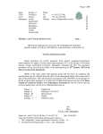
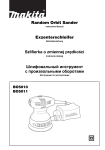
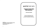
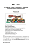
„GETONA SC-1007” („SC - 0705”) Technical Description and User Guide December- 2008 MG Solutions Ltd. Vrania # 82, entry B, Office 4, 1309 Sofia, Bulgaria tel: (+359-2) 832 9182 fax:(+359-2) 931 3723 [email protected], www.MGsolutions-bg.com Getona SC-1007 Technical description and instructions for exploitation. CONTENTS: 1. SUMMARY. ................................................................................................................................................... 3 2. INSTALATION. ............................................................................................................................................. 3 3. MACHINE AND APPLIANCES.................................................................................................................... 5 4. PROTECTING THE ENVIRONMENT. ........................................................................................................ 8 5. SAFETY INSTRUCTIONS ............................................................................................................................ 8 6. TRANPORT.................................................................................................................................................... 9 7. STORAGE ...................................................................................................................................................... 9 8. MARKINGS.................................................................................................................................................... 9 9. OPERATING WITH THE MACHINE......................................................................................................... 11 10. TECHNICAL MAINTENANCE .................................................................................................................. 19 11. TROUBLESHOOTING ................................................................................................................................ 19 12. WARRANTY................................................................................................................................................ 20 13. PACKING SLIP ............................................................................................................................................ 21 14. SALES & SERVICE ..................................................................................................................................... 21 MG Solutions Ltd. Page 2 of 21 Technical description and instructions for exploitation. Getona SC-1007 1. SUMMARY. 1.1. Before you start using the machine for the first time IMPORTANT: REMOVE THE TRANSPORTATION CLUTCHES AND SCREWS. Preparing to turn the machine on for the first time. Check the external solidity of this product; Check for contamination and if there is such, clean it out; Mount the toolhead – See point 2.3.1; Turn the machine to the compressor (the installation for air pressure); Check the condition of the connection cables and plug them in; Turn the machine to the working station throughout an USB cable; Put the disc with the software in the CD reader and install the software, following the instructions; Switch on the machine Check the good working order of the product by executing the control task. Daily switching on Switch on the machine; Start the software in the working station; Watch the display of computer as error messages may appear Follow the indications of the manometers for the level of the pressure in the pneumatic system; ATTENTION! If an error message appears or the product doesn’t show the signs of a good working order, you shall address the competent specialists to locate and repair the failure. Read carefully these instructions for the user to find out the whole functionality of your machine. 2. INSTALATION. 2.1. Unpacking the machine. Unscrew the screws the package’s cover is fixed with and take it off; Take off the fixing transport elements; Take the machine out of the package; Take off the packages with the toolhead. 2.2. Removing the transportation clutches and screws. The machine is delivered in a special package to prevent damage during transport and transfer and is equipped with two fixing elements, fixed with screws „B” to the walls of the container and a fixing bar „A” for fixing the toolhead – Figure 1. MG Solutions Ltd. Page 3 of 21 Technical description and instructions for exploitation. Getona SC-1007 Figure 1 – Fixing transport elements. Before taking the machine out of the package the fixing elements MUST be removed. Cut the fixing bar - „A”; Move the toolhead in the middle of the working table. Unscrew the four screws “B”; Take off the fixing elements. Note: If you need to move the machine you must always mount the transportation clamps and screws and transport it in the upright position. 2.3. Instalment. Install the machine on a stable desk or a table near electricity connections and a personal computer. Make sure that the desk (the table) is sure-footed on the floor and the 4(four) legs of the machine are standing firmly onto the panel of the desk (the table). Mount the toolhead; Turn the machine to the working station throughout an USB cable Turn the machine to the compressor or to the installation for air pressure Put the disc with the software in the CD reader and install the software following the instructions; 2.3.1. Mount the toolhead. Usually the machine is delivered with a mounted toolhead. If it is not so, follow the instructions below to mount the toolhead: Remove the packaging from the toolhead; Take off the protective band upon the rubber gasket – figure 2, situation „A”, step 1; Set the toolhead so its hinges lay in the hinges of the carriage; Set the cotters in the holes of the hinges and with the help of a flat screw-driver tighten the hinges of the carriage - figure 2, situation „A”, step 2; Carefully coincide the 2(two) parts of the coupling of the toolhead and the carriage and connect them by pressing the toolhead to the carriage; MG Solutions Ltd. Embed the toolhead to the carriage with the fixing screw. - figure 2, situation „A”, step 3. Page 4 of 21 Technical description and instructions for exploitation. Getona SC-1007 Figure 2 – Mounting the toolhead. 2.4. Connecting to the electric grid When connecting to the electric grid you shall take into consideration the local standards; The plug through which the machine is connected to the electric grid shall be grounded in accordance to the specified standards. The law states that the machine shall be grounded. The manufacturer carries NO responsibility about property damages or injuries of people or animals caused by direct or indirect breaking the rules above; Information about the voltage, the consumption power, and the necessary electric protection are given on the back side of the machine; If it is necessary to replace the electric cables this shall be done only by a qualified electrician; The machine conforms the European standards of safety, the ES 93/68 EIO Directive and the EN 61029 Standard; Do not use extenders or couplings; After you have fulfilled the above requirements, connect the lead cable to the electric grid 220-240 V, 50/60 Hz – figure 2, situation „C”. 3. MACHINE AND APPLIANCES 3.1. Composition of the machine. The machine Getona SC-1007 is composed of: Working table; Toolhead The toolhead is delivered in one of two varieties – with or without a module of oscillation; Control system; Power supply block; 3.2. Technical characteristics Outside dimensions - 1326/1147/415 mm; Weight – 93 kg; Working pressure of the compressor - 0.25 MPa ÷ 0.65 MPa; Storage temperature - from -20оC to + 60оC; Working temperature - from 0оC to + 45оC; Working area for cutting and creasing – 1000/700 mm; MG Solutions Ltd. Page 5 of 21 Technical description and instructions for exploitation. Getona SC-1007 Ability to cut and crease by rotating the pasteboard – 1 000/1 400 mm. When cutting and creasing pack aches by rotating the pasteboard there is a single interruption of the process to rotate the pasteboard. 3.3. Structure and operation principle. Getona SC-1007 is a compact and a reliable device, constructed of modules. It works in normal ambient conditions. It is hardware and software compatible with personal computers PC. 3.3.1. Construction of the machine. The construction of the machine Getona SC-1007 provides working convenience, compactness and implementation of the technical requirements towards the product. The basic modules are connected in between by means of electrical and pneumatic couplings in a common construction by using cable links, mounting plate, air tubes, mechanical connectors, supporting elements, etc. To lower the working noise rubber and flexible metal connectors are used to transmit the motion; also noise absorbing device and isolation are applied. The mechanical and the electric construction of the product provide its functioning in normal (office) conditions for work. Its outside dimensions allow positioning the machine on office desks or tables. The low values of noise allow the machine to work in small premises and offices, without disturbing the work of the rest of the personnel. The management of „Getona SC - 1007” is done by a personal computer throughout a special software, included in the set of the machine. The machine is delivered ready to work and additional settings are not necessary. You shall only unpack it, put it on the appropriate place and connect it to the electric grid. 3.3.1.1. General construction The general construction of the machine is presented on figure 3. Control of the toolhead Carriage Toolhead Adjusting system of the cutting instrument Working table Emergency OFF button Master switch Vacuum regulator Controller of the pressure on the creasing instrument Controller of the pressure on the cutting instrument Motion in X direction Motion in Y direction Undercarriage Figure 3 - General construction of the machine MG Solutions Ltd. Page 6 of 21 Technical description and instructions for exploitation. Getona SC-1007 The general construction of the toolhead with the working instruments is presented on figure 4 Pen corps Toolhead corps Adjusting system of the cutting instrument Adjusting nut of the creasing instrument Supporting plate of the toolhead Lighter Pen Cutting instrument Creasing instrument Figure 4 - General construction of the toolhead 3.3.2. External connectors. The external connectors of the machine are presented on figure 5. USB connector Power supply 5A switch connector Figure 5 - The external connectors. Vacuum connector 3.3.2.1. Description of the external connectors and the control devices. Power supply connector –connects the machine to the electric grid. 5 A switch –prevents higher than the normal consumption from the elements of the machine; Main power supply switch –switches the machine on and off; Adjusting of the vacuum ventilator –switches the ventilator for vacuum fastening of the material on and off; Emergency OFF button –immediately switches off the power supply of the machine when emergency occurs. MG Solutions Ltd. A special connector USB – serves for turning the machine to the managing computer ; Page 7 of 21 Technical description and instructions for exploitation. Getona SC-1007 Controller of the pressure on the creasing knife – regulates the pneumatic pressure in the controlling cylinder of the creasing knife; Controller of the pressure on the cutting knife - regulates the pneumatic pressure in the controlling cylinder of the cutting knife, in the cylinder of the mechanism for pressing the material, and in the pen cylinder 4. PROTECTING THE ENVIRONMENT. 4.1. Package. The packaging material can be recycled 100% and it is marked with the recycling sign . 4.2. Getona SC-1007. The machine is produced from suitable for recycling materials. Should you decide to dispose of the machine, please make sure you follow the existing codes for disposal of electronic equipment. Before you dispose it cut off the plug and the power supply cable, to ensure that the appliance will not be switched to the electric grid anymore. 4.3. Advices on protecting the environment. When the machine is operating it does not emit environmentally harmful waste. The remnants from the materials used during the machine operation are recyclable 100 %. When disposing the waste, please make sure you follow the existing codes for waste disposal. 5. SAFETY INSTRUCTIONS The machine conforms to the European Safety Regulations - EC Directive 93/68/ЕИО and Standard EN 61029-1. ATTENTION! You must follow the general safety rules in order to limit the risk of fire, electrical shock and human injury: You must read these safety instructions before setting to work with this product. Please keep these instructions. 5.1. Safety rules and instructions: There is no need for special staff training for the proper usage of the machine. It is enough to read this technical description and user guide; There is no need to use personal safety clothes or devices during usage of the machine; There is no need to apply additional safety barriers or protective devices; You should use the machine only for its intended purpose – making of carton packaging samples and other similar objects as described; The installation of the machine as well as the electrical and pneumatic connections must be performed according to these instructions while following the local safety guidelines (see “Installation Instructions”); Do not attempt to move the toolhead by hand when the machine is switched on. There is no residual danger after switching the machine off; The packaging materials may present danger to children. Please keep all packaging materials (plastic bags, etc.) out of reach of children. 5.2. For a safe working environment: Keep your workplace clean and in good order. Disorderly workplaces provoke accidents; Do not use the machine in a damp environment; Do not use the machine near flammable liquids or gases; Keep your workplace well lit; MG Solutions Ltd. Page 8 of 21 Technical description and instructions for exploitation. Getona SC-1007 Keep from electrical shock – avoid skin contact with the ground or grounded surfaces (tubes, radiators, stoves, refrigerators, etc.); Do not allow people who are not directly involved with the work of the machine nearby. Keep children away. Do not allow any contact with the connecting electrical cable. Do not overload the machine. It works best and safest within the specified workload conditions; Do not use the machine for applications and materials that are not specified – for example, do not cut materials with metal particles inside; Wear appropriate work attire. Do not wear wide clothes or long-hanging jewellery – they could be caught by the moving parts of the machine. Wear a protective headscarf, if you have long hair; Do not use the electrical cable for anything else. Never pull the cable in order to disconnect the electricity. Keep the cable away from heat, oil and sharp edges; Keep appropriate body standing and balance at all times. Do not stretch or perform physical exercises near the machine Do not put your hands close to the moving parts of the machine; Maintain the machine with care. Keep the cutting tools well sharpened and clean for better and safer performance. Follow the cleaning and oiling instructions. Follow the tool exchange instructions; Disconnect the machine from the electrical supply when not in use, before any servicing procedure an before tool exchange; To avoid unintentional start, always check if the power switch is in Off position before plugging the electrical cord; Do not work with the machine when tired; Any broken or damaged part (except the cutting tools) must be repaired or exchanged by an authorised service technician; Attention! Any use of tools and appliances for exchanging of the cutting tools that are not recommended by this instruction may lead to injuries; Always use authorised service centres or technician for machines repairs. The machine conforms to the safety requirements only if it is maintained and repaired by authorised service technician who uses original spare parts. Otherwise there is a great risk of accidents and personal injuries. 6. TRANPORT Unplug the power; Put the machine in the transport package; Put the transport fixing elements – figure 1. Transport the machine in the upright position. 7. STORAGE Store and use the machine in dry, well-ventilated places. The relative humidity should be no more than 75% and the temperature within the limits of 0C to 55C. 8. MARKINGS The following markings are present on the back side of the machine: A plate containing the following information: Model name of ther machine; Model number; Maximum electrical power (300W), voltage (230V ~), frequency (50Hz), and maximum current (1.3A); MG Solutions Ltd. Page 9 of 21 Technical description and instructions for exploitation. Getona SC-1007 Serial number and year of manufacture; Name of the manufacturer; Address and country of manufacture; Certificate symbol - Sign – Do not tilt! There are lead seals over some of the panel screws of the machine. The seals guarantee that the machine has passed quality control and is fit for service. Do not remove the lead seals as this will render the warranty void. The following markings are on two sides of the packaging: A plate with the following information: Model name of ther machine; Model number; Serial number and year of manufacture; Name of the manufacturer; Address and country of manufacture; Sign – Do not tilt! Sign – Handle with care! Sign – Keep dry! Sign – This side up! Sign – Packaging can be recycled 100% MG Solutions Ltd. Page 10 of 21 Technical description and instructions for exploitation. Getona SC-1007 OPERATING WITH THE MACHINE 9. Work of the machine is being managed by the software product GSC Controller. Detailed information and user manual for this product can be found in GSC Controller User Guide 9.1. Basics. 9.1.1. Format of the acceptable files. The machine accepts and processes files in HPG format. You can find the commands type in the following document „A Guide to the HP-GL language”. 9.1.2. Measuring units. Notice: The representation of the size of the screen, always in millimeters, not depending on the units set in the HPGL instructions in the working file or on the settings set in the machine. The machine accepts and processes files containing different angular and linear measuring units. The measuring units which the machine must accept and operate are given by the user through program’s customization or the HP-GL commands. The possible measuring units are: Linear measuring units: 1/40 of a millimeter, which is compared to 1 step of the machine; 1 millimeter, which is compared to 40 steps of the machine; 1 inch, which is compared to 1016 steps of the machine. Angular measuring units: Degrees – the circumference is divided in 360о; Grads – the circumference is divided in 400о; Radians – the circumference is divided in 2Pi radians. By default the measuring units are: One linear measuring unit of the machine is equal to 1 mm with accuracy up to 1/100 mm; One angular measuring unit of the machine is equal to 1о with accuracy up to 1/100о. Notice: Representation of the screen size is always in millimeters, not depending on the units set in the HPGL instructions in the working file or on the settings set in the machine. 9.1.3. Tools for work. The following tools are differentiated in the machine: Laser beam – tool No 1. On the screen the lines and the catenaries are represented in yellow color; Pen – tool No 2. On the screen the lines and the catenaries are represented in blue color; Creasing tool – tool No 3. On the screen the lines and the catenaries are represented in green color; Cutting tool – tool No 4. On the screen the lines and the catenaries are represented in black color. 9.2. Switching the machine on and off. 9.2.1. Switching the machine on. Before you switch the machine make sure that the emergency OFF button is not in OFF position. You can check it by turning clockwise the sponge of the emergency OFF button until resistance occurs. To switch on the machine set the main switch in position ON.. The user program is started with two consecutive clicks on the icon computer. MG Solutions Ltd. of the screen of the personal Page 11 of 21 Technical description and instructions for exploitation. Getona SC-1007 After starting the program click on the button condition. , to put the machine in a normal working button the main dialog window is loaded and the toolhead moves to the After pressing the point of origin of the machine frame of reference– figure 6. Figure 6. 9.2.2. Switching the machine off. Before switching off the machine ,deactivate the program in the personal computer. Switching the machine off is done by putting the main switch in a position „Switched off”. Warning: After switching off the machine put the indicator of the regulating mechanism for cutting depth in condition zero. If you miss this operation, during the next switching on the machine you risk to damage the cutting coverage mounted on the working table or to break the knife. 9.3. Changing the toolhead You must switch the machine off before changing the toolhead! Removal of the toolhead: The removal of the toolhead is given on Figure 7, A and should be performed in the following sequence: Unscrew the holding pins from the hinges of the carriage and remove them – Figure 7, A, Step 1; MG Solutions Ltd. Unscrew the fixing screw and remove the toolhead – Figure 7, A, Step 2. Page 12 of 21 Technical description and instructions for exploitation. Getona SC-1007 Figure 7 – Removal of the toolhead. Installation of a new toolhead The installation of the toolhead is given on Figure 7, B and should be performed in the following sequence: Take the toolhead out of its packaging; Remove the protective sticker from the ribbon gasket – Figure 7, B, Step 1; Place the toolhead, so that its hinges connect with the hinges of the carriage; Place the holding pins inside the openings of the hinges and screw them in – Figure 7, B, Step 2; Carefully match the coupling of the toolhead and the carriage and connect them by pressing of the toolhead towards the carriage; Fasten the toolhead to the carriage with the fixing screw – Figure 7, B, Step 3. 9.4. Exchange of the cutting/creasing tools without a vibration mechanism. The change of the cutting (creasing) tools is shown on figure 8. Removal of the cutting/creasing tool: Unscrew the fixing screw of the cutting (creasing) tool- figure 8, situation “A” and „B”, step 1. Change the cutting (creasing) tool of the toolhead by pulling down – figure 8, situation „B”, step 2. MG Solutions Ltd. Page 13 of 21 Technical description and instructions for exploitation. Getona SC-1007 Figure 8 – Exchange of the cutting and creasing tools Installation of the cutting/creasing tool: The installation of a new cutting/creasing tool is performed in reverse sequence, provided that the toolhead is tilted upwards: Put the new cutting (creasing) tool on the toolhead - figure 8, situation „B”, step2; Clamp the fixing screw of the cutting (creasing) tool- figure 8, situation „A” and„B”, step1; 9.4.1. Exchange of the cutting knife of the toolhead without a vibration mechanism. The order for exchange of the cutting knife is shown on figure 9. Figure 9 – Exchange of the cutting knife Work sequence: Remove the cutting tool from the toolhead; Take the plastic cup of the cutting tool with your right hand. Rotate the large regulating screw clockwise with your left hand to the end. The cutting knife should fully retract inside the cutting tool – Figure 9, A, Step 1; Untighten the fixing screw of the cutting knife – Figure 9, B, Step 1; Using a pin or a paper clip, push the cutting knife outside of the cutting tool – Figure 9, B, Step 2; MG Solutions Ltd. Turn the cutting tool horizontally so that the fixing screw is towards you – Figure 9, C & D; Page 14 of 21 Technical description and instructions for exploitation. Getona SC-1007 Place the cutting knife (sharp edge upwards) inside the slot of the cutting tool and with a wooden block push it inside until it fully disappears – Figure 9, C, Step 1; Tighten the fixing screw of the cutting knife – Figure 9, D, Step 1; Turn the cutting tool vertically. Take the cup of the cutting tool with your right hand. Rotate the large regulating screw counter clockwise with your left hand until the cutting knife appears and reaches the desired height – Figure 9, E, Step 1; Place the cutting tool in the toolhead. 9.4.2. Exchange the cutting knife of the toolhead. The order for exchanging the cutting knife of the toolhead with a vibration mechanism is shown on figure 10. Figure 10 – Exchange of the cutting knife. A working order: Switch off the oscillation of the knife from the dialog „Tools”. Put the depth cutting regulation mechanism in position zero of the raw and the fine setting scale–fig. 10, situation „A”, step 1; Put the plastic plate under the blade of the cutting knife - figure 10, situation „A”, step 2; Unknot the fixing screws of the cutting knife - figure 10, situation „A”, step 3; By the help of the plastic plate raise the cutting knife, so that it is hidden in the cutting instrument - figure 10, situation „B”, step 1; Straiten slightly one of the fixing screws of the cutting knife - figure 10, situation „B „C”, step1; Unknot the fixing screw of the cutting knife and take off the knife - figure 10,situation „C”, step 2; Put the new cutting knife and with the plastic plate ,put it in the cutting tool ,then straiten one of the fixing screws- figure 10,situation „C”, step 3; MG Solutions Ltd. Put the cutting tool in the cutting mechanism bed – figure 10, situation „D”, step 1; Page 15 of 21 Technical description and instructions for exploitation. Getona SC-1007 Straiten the fixing screw of the cutting tool - figure 10, situation „D”, step 2; Put the plastic plate under the cutting mechanism – figure 10, situation „E”, step 1; Put the depth cutting mechanism in position zero of the rough and the fine setting scale – fig. 10, situation „A”, step 1; In the main window press to open the setting dialog of the working tools; Press the button to take down the cutting mechanism in position down and to press the plastic plate; Unknot the fixing screws of the cutting knife, so that the knife goes down and hems the plastic plate, then straiten the fixing screws - figure 10, situation „E”, step 2; Press the button Switch on the functionality ; and press the buttons and consecutively; 9.4.3. Quality check upon exchange of the cutting knife After exchanging the cutting knife, you should check the precision of the mounting of the new knife: Work sequence: Place two cartons 1-1½ mm thick on the work table and fix them; Regulate the height of the knife, so that it cuts at 1-1½ mm; Press the Choose button to open the Tool Setup Dialogue; ; button. The knife should rotate 90о and move down. Press the button Press the again to move the knife up. Repeat this sequence four times in order to form four small cuts like a cross. Remove the upper carton and use a magnifying glass to examine the cuttings of the knife. If the knife is mounted properly, the cuttings should look like Figure 11, A, position 1. The cuttings should not deviate more than one width of the knife as shown on Figure 11, A, position 2; If the mismatch is greater than one width of the knife – Figure 11, B, position 1 & 2, please remove and then install the knife again point 9.4.1 (9.4.2) Then perform the same quality check; MG Solutions Ltd. Press the button to close the dialogue. Page 16 of 21 Technical description and instructions for exploitation. Getona SC-1007 Figure 11 9.5. Regulation of the depth of cutting/creasing. Regulating the cutting depth of a toolhead without a vibration mechanism and of a toolhead with a vibration mechanism is done in a different way. Figure 12 presents the cutting and creasing tools of a toolhead without a vibration mechanism with a side view. The large regulating knob of the cutting tool is graduated with small and large markings. The large markings are numbered 1 to 7 – Figure 12, A. Every one of the small markings corresponds to 0.050 mm change of the depth of cutting. The regulating knob of the creasing tool is graduated in the same way – Figure 12, B. Turning of the regulating knob clockwise reduces the depth of cutting/creasing. Turning it counter clockwise increases the depth of cutting/ creasing. Figure 12 – Regulation of the depth of cutting/creasing On figure 13 is shown the look of the mechanism for regulating the cutting depth of the toolhead with a vibration module ,looked from above. Figure13 - A mechanism for regulating the cutting depth of the toolhead with a vibration mechanism. The regulatory mechanism is working with a fine and a rough scale of realizing of the cutting depth. MG Solutions Ltd. Page 17 of 21 Technical description and instructions for exploitation. Getona SC-1007 The fine scale („A”) of the regulating mechanism is graduated with small and large scales. Large scales are labeled from 10 to 90 through 10, every large scale responds at 0.10 mm. Every small scale responds at 0.020 mm. The value of the rough scale („B”) is shown in a special window and it can be from 0 to 14, every value responds at the cutting depth in millimeters. A turnover from the fine scale changes the value of the rough scale with 1mm. During turning the propeller („C”) the mechanism for regulating the cutting depth clockwise increases the cutting depth, turning back-clockwise the cutting depth decreases. After regulating the cutting depth always stop the mechanism for regulating the cutting depth with the help of the stopper(„D”). Warning: After cutting always leave a part of the cut material under the mechanism or make the cutting depth 0.00 mm and fix the regulatory mechanism. If this is not done the next time the machine is switched the cutting knife can be broken or the cutting mat can be cut. Work order for cutting depth regulation: The regulation of the cutting depth is performed when the machine is switched on. Check the air pressure of the cutting tool; Take two pieces of the same type of carton you are going to use and place them one on top the other under the cutting tool; Press the Choose Depress the two cartons with your hand and press the button to open the Tool Setup Dialogue ; side of 15 mm. Alternatively, press the button to cut a square with a button to cut a circle with diameter of 10 mm.; Check the cutting. The upper carton should be fully cut while the lower carton should not be marked. If this is not so, use the regulating knob to adjust the cutting depth and check the setting again in the same manner. Press to close the dialogue. Warning: If the setting of the cutting depth is not done right you risk to damage the cutting coverage, mounted on the working table or to break the knife. Work order for creasing depth regulation: The regulation of the creasing depth is performed when the machine is switched on and after the regulation of the cutting depth: Check the air pressure of the cutting tool; Take a sheet of the carton to be used and place it under the toolhead; Switch on the vacuum to hold the carton in place; Press the Choose Press the button to open the Tool Setup Dialogue ; button to crease a square with a side of 35 mm; Check the creasing. The creasing is considered a good one if the depth of the crease is about one half of the thickness of the carton. If this is not so, adjust the creasing depth with the regulation knob; Repeat the regulation until a satisfactory result; Press MG Solutions Ltd. to close the dialogue. Page 18 of 21 Technical description and instructions for exploitation. Getona SC-1007 10. TECHNICAL MAINTENANCE The technical maintenance ensures: Constant availability of the machine to its full capabilities; Pre-emptive discovery and elimination of potential problems to ensure trouble-free operation; Removal of factors causing excessive wear and failures; Extension of the useful life of the machine and reduction of repair times. Therefore: Strictly follow the instructions of the maintenance and user guides; Keep the connecting and moving parts of the machine clean; Perform monthly technical check-ups. For maintenance of the machine use only instruments in good working order. During technical maintenance it is FORBIDDEN to: Open the control block; Use gasoline, kerosene, diesel fuel or other solvents; Change the construction and placement of the amortization devices and feet of the machine; Monthly maintenance The monthly maintenance should include: Clean the outside surfaces of the machine and look for possible wear and tear; Carefully inspect the cables and their connectors; Lightly coat the rubbing parts of the machine with machine oil; Check the tension of the belts of the electric motors and the linear movements; Switch on the machine and see if the software boots properly. Always refer to an authorised technician to fix problems that you notice during monthly maintenance, except for cable exchanges that you can do yourself. Long-term maintenance Long-term maintenance should be performed every 6 months and should include: Perform the same operations as for monthly maintenance; Clean the control block with alcohol or other cleaning agent suitable for soft LCD monitors; Check the cable connectors and clean the connecting elements with alcohol; Check the isolation along the whole length of the cables; Always refer to an authorised technician to fix problems that you notice during maintenance, except for cable exchanges that you can do yourself. 11. TROUBLESHOOTING Very often problems with the machine are due to minute causes and can be fixed quickly. Getona SC - 1007 does not start, there is no light and the control block does not start: Check for the following: Is the machine connected to the electric grid? Is the emergency shut off switch pressed? Is there electricity available? Getona SC - 1007 turns on, but there is no pneumatic pressure and the tools can not move up/down: MG Solutions Ltd. Page 19 of 21 Technical description and instructions for exploitation. Getona SC-1007 Check for the following: Are the pressure regulators set to zero pressure? Is there a leak of pressurized air from the pneumatic tubes? Getona SC - 1007 does not receive data and does not perform the set task: Check the following: Are the communication cables and ports to the PC properly connected? Are the communication cables and ports on the machine properly connected? Getona SC - 1007 is moving, but the carton is not creased nor cut: Check the following: Is the cutting knife broken? Is the set cutting depth enough? Is the set creasing depth enough? Is the set air pressure enough? Getona SC - 1007 stops suddenly while working: Check the following: Is there electrical supply? Is there accumulation of dirt on the rubbing parts of the machine? Are the terminal switches engaged (in an attempt to move the toolhead outside of the working area)? Always refer to an authorised technician to fix problems that you notice during machine operation. ATTENTION! It is strictly forbidden to open the covers and panels of the machine except by authorised technicians or service centres. Opening the machine voids the warranty. 12. WARRANTY The warranty period is 12 months from the date of delivery to the customer, but no more than 18 months from the date of manufacture. The warranty is valid only if the machine has been used for its intended purpose according to these instructions and guidelines. If during the warranty period the machine malfunctions due to improper use or storage by the customer, the repairs are paid for by the customer; The transport expenses for warranty repairs are paid by the customer. Before calling the service centre: Try to troubleshoot the problem yourself (see section 11); Switch off the machine and wait a minute. Switch it on again and check if the problem persists. If after the checks described above the machine still does not work properly, please call your local service centre or directly the manufacturer. Please provide: MG Solutions Ltd. Short description of the defect or problem; The exact model name and number of the machine; The serial number of the machine; Your contact name, address (including the postal code), telephones and e-mail. Page 20 of 21 Technical description and instructions for exploitation. Getona SC-1007 13. PACKING SLIP The machine is delivered in the following configuration: No Item Unit Quantity 1 Getona SC-1007 work bench and movements pc. 1 2 Toolhead with oscillation pc. - 3 Cutting tool (no oscillation) pc. 2 4 Creasing tool pc. 3 5 Power supply cable pc. 1 6 Connecting cable USB pc. 1 7 Cutting knives (package 10 pc. each) package 1 14. SALES & SERVICE MG Solutions Ltd.. 82 Vrania St., entry B, office 4, 1309 Sofia, Bulgaria Tel: (+359-2) 832 9182, Fax: (+359-2) 931 3723 E-Mail: [email protected] MG Solutions Ltd. Page 21 of 21