1
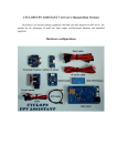
Intelligent Pump Controller
Installation & Operation Manual
L932/B
Ver.1.1
Installation & Operation Manual
Intelligent Pump Controller
L932/B
Conventions used in this manual
In the manual the following symbols will be used:
!
Generic danger Failure to comply with the safety regulations that follow can
irreparably damage the controller or equipment.
Electric shock risk Failure to comply with the safety regulations that follow
can cause death or serious personal injury.
WARNINGS
Read this manual carefully before any operation.
Please keep this manual for future use.
WARNING!!
■Before carrying out any installation or maintenance operation, controller must be disconnected form the
power supply;
■Don't open the cover during running the controller;
■Don't put wire ,metal bar filaments etc into the controller;
■Don't splash water or other liquid over the controller;
! CAUTION
■The electrical and hydraulic connections must be carried out by competent, skilled.qualfied personnel;
■Never connect AC power to output uvw terminals;
■Ensure the motor, controller and power specifications matching;
■Don't install the controller in the following condition;
55
corrosive gas or
corrosive liquid
mechanical shock
Extreme heat and cold,
acceptable temperature
range: -25℃ +55℃
Salt
Salt mist corrosion
Installation & Operation Manual
Rain and Moisture
Ver.1.1
flammable material:
solvent
Installation & Operation Manual
Intelligent Pump Controller
L932/B
TABLE OF CONTENTS
1 INTRODUCTION … … … … … … … … … … … … … … … … … … … … … … … … … … … … … … … … … … … .1.
1.1 Applications … … … … … … … … … … … … … … … … … … … … … … … … … … … … … … … … … … ….1.
1.2 Technical parameter & features … … … … … … … … … … … … … … … … … … … … … … … … … … .1.
1.3 Controller components … … … … … … … … … … … … … … … … … … … … … … … … … … … … … … .3.
2 INSTALLATION … … … … … … … … … … … … … … … … … … … … … … … … … … … … … … … … … … … .5.
2.1 Electrical connection to the power supply line and electrical pump … … … … … … … … … … … .5.
2.2 Parameter Calibration setting & erasing … … … … … … … … … … … … … … … … … … … … … …
.6.
3 ELECTRICAL CONNECTION… … … … … … … … … … … … … … … … … … … … … … … … … … … … … … .7.
3.1 Installing liquid probe or float in the water well … … … … … … … … … … … … … … … … … … … … .7.
3.2 Installing pressure transmitter … … … … … … … … … … … … … … … … … … … … … … … … … … … .8.
3.3 Electrical connection for pressure booster pumping system… … … … … … … … … … … … … … … .9.
4 SET DIFFERENT WORKING PRESSURE VALUE …… …… …… ……… …… …… …… …… ………… .12.
4.1 Cut off pressure value setting… … … … … … … … … … … … … … … … … … … … … … … … … … … .12.
4.2 1 ST Pump cut in pressure value setting… … … … … … … … … … … … … … … … … … … … … … … ….12.
4.3 2 nd Pump cut in pressure value setting… … … … … … … … … … … … … … … … … … … … … … … ….13.
5 BASIC OPERATION… … … … … … … … … … … … … … … … … … … … … … … … … … … … … … … … … .13.
5.1 Switching to MANUAL mode… … … … … … … … … … … … … … … … … … … … … … … … … … … ….13.
5.2 Switching to AUTO mode… … … … … … … … … … … … … … … … … … … … … … … … … … … … … .13.
5.2.1 AUTO mode working logic description … … … … … … … … … … … … … … … … … … … … … .13.
5.3 Pump protection … … … … … … … … … … … … … … … … … … … … … … … … … … … … … … … … ….14.
5.4 Pump last five failure record displaying … … … … … … … … … … … … … … … … … … … … … … … .14.
5.5 Pump accumulative running time displaying … … … … … … … … … … … … … … … … … … … … … .15.
6 COMMUNICATION LINK … … … … … … … … … … … … … … … … … … … … … … … … … … … … … … … .16.
6.1 Basic Function … … … … … … … … … … … … … … … … … … … … … … … … … … … … … … … … … … .17.
6.2 Special Application … … … … … … … … … … … … … … … … … … … … … … … … … … … … … … … … .17.
6.3 Technical parameter … … … … … … … … … … … … … … … … … … … … … … … … … … … … … … ….17.
7 ELECTRICAL CONNECTON FOT PASSIVE DRY CONTACT POINT… … … … … … … … … … … … … .18.
8 TROUBLE SHOOTING GUIDE… … … … … … … … … … … … … … … … … … … … … … … … … … … … ….18.
Installation & Operation Manual
Ver.1.1
Installation & Operation Manual
Intelligent Pump Controller
L932/B
RESPONSIBILITY
The manufacturer is not liable for malfunctioning if the product has not correctly been installed,
damaged, modified, and /or run outside the recommended work range or run outside the recommended
work range or in contrast with other indications given in this manual.
The manufacturer declines all responsibility for possible errors in this operation manual, if due to
misprints or errors in copying.
The manufacturer reserves the right to make any modifications to products that it may consider
necessary or useful, without affecting the essential characteristics.
1 INTRODUCTION
Thank you for choosing our products, we will supply you with cordial and well-around service as well as
ever.
Intelligent Pump Controller model L932-B is an easy to use, programmable controlling & protection
device for duplex booster pump with direct start, three phase, 0.75KW-15KW(1HP-20HP)
1.1 Applications
Model L932-B is specially designed for pressure booster pumping system, by adopting pressure
transmitter (0.5-4.5V), pump user can easily set the different pressure value and observe the dynamic
pressure value in the pipeline.
Typical usage scenarios include:
- Houses
- Holidays houses
- Water supply from wells
- Construction site
- Flats
- Farms
- Industrial plants
1.2 Technical parameter & features
Main features:
■Double pumps control
main pump / standby pump automatically alternate
main pump / standby pump automatically switch against malfunctions
standby pump participate running if required
■Present pressure transmitter with 0.5-4.5V analog signal
■Easily setting the different pressure value and observing the dynamic pressure value
■Eliminates the pressure switches: pressure setting for two pumps; pressure setting for one pump
■Automatic stops the pump in the case of water shortage, protecting it from dry running without
installing float switch or liquid probe in the well
■Auto / Manual switch
■Protect the pump against many faults
■Dynamic LCD displaying the real pressure value
■Dynamic LCD displaying pump running information
■Pump accumulative running time displaying
■Pump last five fault record displaying
■Pump shaft anti rust
■Present remote monitor
■Present one dry contact point
.1.
Installation & Operation Manual
Ver.1.1
Installation & Operation Manual
Intelligent Pump Controller
L932/B
The following chart shows main technical parameters of Model L932/B
Main technical characteristic
Control characteristic
pressure control
Control method
Manual / Auto
Pressure control characteristic
Pressure transmitter with 0.5-4.5V analog signal
Main technical data
0.75-15KW (1HP-20HP)
refer to the nameplate
Rated output power
Rated input voltage
Trip response time of over load
AC220V-AC415V /50HZ Three Phase
refer to the nameplate
5sec-5min
Trip response time of open phase
Trip response time of short circuit
<2sec
<0.1sec
Trip response time of under / over voltage
<5sec
Trip response time of dry run
6sec
Recovery time of over load
30min
Recovery time of under / over voltage
5min
Recovery time of dry run
30min
Trip voltage of over voltage
115% of the rated input voltage
Trip voltage of under voltage
80% of the rated input voltage
Liquid level transfer distance
≤1000m
Dry run
Over load
Transient surge
Under voltage
Over voltage
Pump shaft rust protection
Protection function
Pump stalled
Short circuit
Three phase unbalance
Phase reversal
Repeated start
Open phase
Main installation data
Working temperature
-25℃ -- +55℃
Working humidity
20% - 90%RH
Degree of protection
IP54
Install position
Horizontal
Unit dimensions ( L x W x H)
31 x 22x 12cm
Unit weight (net)
3.6kg
RS485 technical data
Physics Interface
RS485 Bus Interface: asynchronism semiduplex
Baud rate
1200 bps、2400 bps、4800 bps、9600bps
Default: 9600bps
MODBUS Protocol (RTU)
Protocol type
Installation & Operation Manual
Ver.1.1
.2.
Installation & Operation Manual
Intelligent Pump Controller
⑨
⑪
⑧
⑩
1.3 Controller components
L932/B
①② ③ ④ ⑤ ⑥
⑦
1.Control terminals for electrical connection to float switch/probe
⑫
A
B
2.The terminals for pressure transmitter
3.RS 485 terminals for communication link (remote monitor)
4.USB port
5.Passive dry contacting point
⑬
6.MCB for electrical connection to the power supply
7.Terminals to electrical pump
8.Displaying board
9.Main board
10.Transformer board
⑭
11.AC contactor
12.Remote monitor
13.Adaptor+cable for remote monitor(SC2)
14.Pressure transmitter
⑮
voltage displaying
area
15.Wall-mounting spares+ waterproof tape for the cable of pressure transmitter
ABC
888 888
UNDER V
A
B
V C
OVER V DRY RUN
OVER LOAD PUMP STALLED
A B C PUMP NO CALIBRATION
fault displaying
area
.3.
THREE PHASE UNBALANCE
888
Psi
Bar
Stop Start 1 Start 2 Start 3
Lo
w
MS
H
V%
A
ampere displaying
area
Hig
pump running status
displaying area
REPEATED START
PHASE REVERSAL
A B C PUMP
A B C OPEN PHASE
AUTO MANUAL
Installation & Operation Manual
Ver.1.1
Installation & Operation Manual
Intelligent Pump Controller
L932/B
Meaning of the icons shown on the LCD
Meaning/Description
Icon
pump parameter configuration icon, when this icon appears, pump control box
is in parameter adjusting manual;
time displaying icon, when this icon appears, it means pump control box is
displaying some parameter of time, eg: pump accumulative running time (unit:
hour); counting down etc
pump fault icon, when this icon appears, it means pump control box is displaying
some fault information;
ON LINE
ON LINE
V
network connection error icon, when this icon appears, it means there is no
network connections or network connection error between pump control box
and SC(slave controller) or computer;
network normal connection icon, when this icon appears, it means the network
connection between pump control box and SC (slave controller) or computer is
normal;
voltage
M
S
second
H
hour
%
percent
A
ampere
minute
pump running
pump stops running
low pressure or lack of pressure in the pipeline or pressure tank
L.
P
H.
L.
P
H.
P
P
high pressure or full of pressure in the pipeline or pressure tank
A
pump A
B
pump B
C
pump C
Installation & Operation Manual
Ver.1.1
.4.
Installation & Operation Manual
Intelligent Pump Controller
L932/B
Meaning/Description
Icon
Stop
pressure value for cut off setting
Start 1
pressure value for 1 st pump cut in setting
Start 2
pressure value for 2 nd pump cut in setting
Start 3
pressure value for 3 rd pump cut in setting
Psi
pressure unit
Bar
pressure unit
Low
low pressure or lack of pressure in the pipeline or pressure tank
Hig
high pressure or full of pressure in the pipeline or pressure tank
2 INSTALLATION
2.1 Electrical connection to the power supply line and electrical pump
① ② ③ ④ ⑤ ⑥
+
+
+
BLACK
U1 V1 W1 PE U2 V2 W2
A+
water well
F2
Air Switch
YELLOW
RED
Upper probe
Lower probe
Com probe
+
F1
B-
+
+
A
B
+
C
Input Power
M
Pump A
M
PE
Pump B
Pressure
Transmitter
DANGER Electric shock risk
Before carrying out any installation or maintenance operation, the L932/B should be
disconnected from the power supply and one should wait at least 2 minutes before
opening the appliance.
Never connect AC power to output U1 V1 W 1 U2 V2 W2 terminals.
! Don't put wire, metal bar filaments etc into the controller.
! Ensure the motor, controller and power specifications matching.
! The electrical and hydraulic connections must be carried out by competent, skilled,
qualified personnel.
.5.
Installation & Operation Manual
Ver.1.1
Installation & Operation Manual
Intelligent Pump Controller
L932/B
2.2 Parameter Calibration setting & erasing
To achieve best level of protection of the pump, it is essential that parameter calibration must be done
immediately after successful pump installation or pump maintenance.
Setting the parameter calibration(Pump A)
- Press the MODE key to switch to manual state, make sure the pump not running and LCD screen
displaying:
380
flash
00
V
00
A B C PUMP NO CALIBRATION
Bar
Lo
A
w
MANUAL
- Press the A START key to run pump, confirm the pump and all pipe network in normal working state
(including voltage, running ampere et); LCD screen displaying:
380
flash
V
A B C PUMP NO CALIBRATION
80
00
Bar
Lo
A
w
PUMP
A
MANUAL
- Press the
STORE
SET
button; The L932/B makes a "Di" sound and starts countdown, LCDscreen displaying:
08
00
A B C PUMP NO CALIBRATION
Bar
Lo
S
w
PUMP
A
MANUAL
- Pump A stops running and parameter calibration completed, LCD screen displaying:
380
V
00
00
Bar
Lo
A
Note:Parameter calibration of pump B is
same as pump A,just by pressing
w
MANUAL
B START button instead of A START
Pump A is ready for running
Erasing former parameter calibration
When pump is reinstalled after maintenance or new pump is installed, user must erase the former
parameter calibration and a new calibration must be done.
Erasing the parameter calibration(Pump A)
- Press the MODE key to switch to manual state, make sure the pump not running and LCD screen
displaying:
380
V
00
00
Bar
Lo
A
w
MANUAL
Installation & Operation Manual
Ver.1.1
.6.
Installation & Operation Manual
Intelligent Pump Controller
L932/B
- Press the A STOP key and release till L932/B makes a "Di" sound, L932/B recover the default factory
setting and LCD screen displaying:
380
flash
V
00
00
A B C PUMP NO CALIBRATION
Bar
Lo
A
w
MANUAL
Note:Erasing the Parameter calibration of pump B is same as pump A, just by pressing
B STOP button instead of A STOP
3 ELECTRICAL CONNECTION
3.1 Installing liquid probe or float switch in the water well
Liquid probe installation
signal cable
Wrap the signal cable and
down-lead of sensor
fixation cone
down-lead of
sensor
installation stand
Upper probe
Lower probe
Com probe
!
In event of high risk of electric storms (lightning) or when liquid medium in well or tank or sump is
very dirty it is recommended float switch is used.
Float switch installation
Upper level (ON)
Lower level (OFF)
!
If the float switch is equipped
with three wires use the BLACK
and BROWN wires. In event of
different colors use a multimeter
to identify correct connections
as follows:
Lower level no reading OFF
Upper level-positive reading-ON
!
.7.
DO NOT ENCASE SENSOR LEADS, FLOAT SWITCH WIRE OR SIGNAL CABLES IN METAL PIPES. USE
PVC OR PE TUBING.
Installation & Operation Manual
Ver.1.1
Installation & Operation Manual
Intelligent Pump Controller
L932/B
3.2 Installing pressure transmitter
Technical parameter
The following chart shows the main the technical parameters of pressure transmitter
Main technical data
Value
Measure Range
0-2.5Mpa
Power Supply
5±0.5VDC
Output Signal
0.5-4.5V
Accuracy
±2%FS(-10℃100℃)
Overload Pressure
2×RP(rated pressure)
Broken Pressure
3×RP(rated pressure)
Insulation
≥10MÙ@50V
Response Time
<10ms
Wires
Three-wire
Elec. connector
Packard
Pressure Port
G1/2
Shell Protection
IP65
Dimension & Pin definition
52.5±1
32.2±0.1
12
12
a
22
b
c
17
R2
21.6
Pin definition
a
VOUT
Yellow color wire
b
VCC
Red color wire
c
GND
Black color wire
Installation & Operation Manual
Ver.1.1
.8.
Installation & Operation Manual
Intelligent Pump Controller
L932/B
3.3 Electrical connection for pressure booster pumping system
① ② ③ ④ ⑤
① ② ③ ④ ⑤ ⑥
check valve
⑥
A+ B-
A+
B-
R
S
T
A
B C
R
S
T
A
B
C
U1 V1 W1 PE U2 V2 W2
M
M
U1 V1 W1 PE U2 V2 W2
valve
water well
.9.
Installation & Operation Manual
Ver.1.1
Installation & Operation Manual
Intelligent Pump Controller
① ②③ ④⑤ ⑥
A+ B-
R
S
T
A
B
C
L932/B
U1 V1 W1 PE U2 V2 W2
check valve valve
Upper probe
Lower probe
Com probe
water well
① ② ③ ④ ⑤ ⑥ A+ B-
check valve
R
S
T
A
B
C
U1 V1 W1 PE U2 V2 W2
valve
Upper probe
Lower probe
Com probe
water well
Installation & Operation Manual
Ver.1.1
.10.
Installation & Operation Manual
Intelligent Pump Controller
① ②③ ④⑤ ⑥
A+ B-
R
S
T
A
B
C
L932/B
U1 V1 W1 PE U2 V2 W2
check valve valve
Start
Stop
water well
① ② ③ ④ ⑤ ⑥ A+ B-
check valve
R
S
T
A
B
C
U1 V1 W1 PE U2 V2 W2
valve
Start
Stop
water well
.11.
Installation & Operation Manual
Ver.1.1
Installation & Operation Manual
Intelligent Pump Controller
L932/B
4 SET DIFFERENT WORKING PRESSURE VALUE
Note: the pressure value degree is CUT OFF SETTING > 1 ST PUMP CUT IN SETING > 2 nd PUMP
CUT IN SETTING
Note: suppose pump user sets the cut off pressure value:
10bar;
1 st pump cut in pressure:
6bar;
2 nd pump cut in pressure value: 3bar;
4.1 Cut off pressure value setting
-press the
key to switch to manual state, make sure the pump not running and LCD screen
380
displaying:
V
00
00
Bar
Lo
A
w
MANUAL
-hold pressing
STORE
SET
key and click
to add or decrease the cut off pressure value;
Stop
-loosen
10
Bar
key, controller makes a DI sound, cut off pressure value setting complete;
STORE
SET
4.2 1 ST Pump cut in pressure value setting
-press the
key to switch to manual state, make sure the pump not running and LCD screen
displaying:
380
V
00
00
Bar
Lo
A
w
MANUAL
STORE
-hold pressing
SET
key and click
to add or decrease the 1 st pump cut in pressure value;
60
Bar
Start 1
-loosen
STORE
SET
key, controller makes a DI sound, cut off pressure value setting complete;
Installation & Operation Manual
Ver.1.1
.12.
Installation & Operation Manual
Intelligent Pump Controller
L932/B
4.3 2 nd Pump cut in pressure value setting
- press the
key to switch to manual state, make sure the pump not running and LCD screen
380
displaying:
00
V
00
Bar
Lo
A
w
MANUAL
hold pressing
STORE
SET
to add or decrease the 2 nd pump cut in pressure value;
key and click
-
30
Bar
Start 2
loosen
STORE
SET
key, controller makes a DI sound, cut off pressure value setting complete;
5 BASIC OPERATION
5.1 Switching to MANUAL mode
Press the
state,press
MODE
key to switch to manual state, L932-B is under the manual control state; under manual
A START
/
B START
key to run A/B pump; press
A STOP
/
B STOP
key to stop A/B pump;
Note: under manual state, the L932-B can not receive the signal from pressure transmitter;
5.2 Switching to AUTO mode
Press the MODE key to switch to auto state, L932-B is under the auto control state; L932-B will run or stop
the pumps according to the pressure value setting;
Note: under auto state, if the pump is running and pump user wants to stop pump running compulsory,
press the MODE key to switch to manual state and pump stops running;
Note: under auto state, if the input power being cut off and recovery power again, the L932/B will enter
operation state after 10seconds countdown;
Note: no matter the L932/B is under auto or manual state, if the input power being cut off and recovery
power again, the L932/B will resume its operation state same as the operation state before power
being cut off;
5.2.1 AUTO mode working logic description
Note: suppose pump user sets the cut off pressure value:
10bar;
st
1 pump cut in pressure:
6bar;
2 nd pump cut in pressure value: 3bar;
.13.
Installation & Operation Manual
Ver.1.1
Installation & Operation Manual
Intelligent Pump Controller
L932/B
1). Normal pressure demanding
If pressure value in the pipeline is 6bar, controller will order single pump to run, when pressure value
reaches 10bar, single pump stops running; controller will alternate dual pumps running automatically
when pressure value varies from 6bar to 10bar;
2). Extra pressure demanding
single pump is running, pressure value in the pipeline still decrease to 3bar, controller will order another
pump to run simultaneously, till the pressure in the pipeline reaches 10bar, double pump will not stop
running;
3). Meaning of the messages & graphic shown on the LCD screen
Description
Messages & Graphic
Lack of water in water well
Full of water in water well
L.
P
H.
L.
P
H.
P
Full of pressure in pipeline or pressure tank
P
Lack of pressure in pipeline or pressure tank
5.3 Pump protection
During pump running, if dry run, over load, under voltage, etc failures happened, the L932/B will
immediately shut down the pump running and automatically execute a check for restarting conditions
after a built in time delay has elapsed. The L932/B will not recover automatically until all the abnormal
situation(s) have been cleared.
If pump stalled, open phase etc serious failures happened, pump user must check the pump and motor
immediately and repair the pump.
5.4 Pump last five failure record displaying
The L932/B can memorize the last five failures of pump, so it is very convenient for the pump users to
analyse the pump running conditions.
Installation & Operation Manual
Ver.1.1
.14.
Installation & Operation Manual
Intelligent Pump Controller
L932/B
Displaying the pump A last five failure record
- Press the MODE key to switch to manual state, make sure the pump not running and LCD screen
displaying:
380
V
00
00
Bar
Lo
A
w
MANUAL
- Hold pressing A STOP key and press
pump failure record;
- Press
A STOP
MODE
key, the L932/B makes a "Di" sound, the L932/B displays
S/N of Failure
Failure Sequence Number
key to quit the failure record displaying;
A
Failure Icon
001
V
PUMP STALLED
ON LINE
THE LATEST FAILURE OF PUMP A IS PUMP STALLED
Note:displaying the pump B last five failure record is same as pump A, just by pressing
instead of A STOP
B STOP
button
5.5 Pump accumulative running time displaying
The L932/B can memorize how many hours of pump running, so it is very convenient for the pump users
to analyse the pump running conditions and do maintenance
Displaying the pump accumulative running time
- Press the
MODE
displaying:
key to switch to manual state, make sure the pump not running and LCD screen
380
V
00
00
Bar
Lo
A
w
MANUAL
.15.
Installation & Operation Manual
Ver.1.1
Installation & Operation Manual
Intelligent Pump Controller
- Hold pressing
MODE
button and press
A STOP
L932/B
key, the L932/B makes a "Di" sound, the L932/B
displays pump accumulative running time record;
Time Icon
00 023
A
H
MANUAL
AUTO
ON LINE
THE PUMP A HAS RUN FOR 23 HOURS
- Press
key to quit the accumulative running time displaying;
A STOP
Note:displaying the pump B accumulative running time is same as pump A, just by pressing
button instead of A STOP
B STOP
6 COMMUNICATION LINK
Model L932/B has communication interface, To adopting simple peripheral equipment (Slave Controller),
pump users can realize long distance monitoring function.
This function is applied for L932/B installed in the basement, pumping room etc, but pump users require
to monitor and control the pump on the ground or in the control room.
A+
B-
A+
B-
Control Room
L932/B
380 160
A
B
V
08
A
Bar
A B
AUTO
INTELLIGNET PUMP
CONTROL PANEL
A
B
PUMP
IP54
SC2
Before carrying out any installation or maintenance
operation, controller must be disconnected from the
power supply;
STORE
SET
Don't open the cover during running the controller;
Don't put wire,metal bar filaments etc into the
controller;
Don't splash water or other liquid over the controller;
L932/B
shield twisted pair cable (SPT)
RS485
1200 meter Max
Pumping
Room
Installation & Operation Manual
Ver.1.1
.16.
Installation & Operation Manual
Intelligent Pump Controller
L932/B
6.1 Basic Function
A
B
Input power
A+
B-
Slave Controller, model SC2 with communication interface can realize long distance monitoring
function. In the control room, pump users can realize all functions of L932/B (Master Controller) through
SC2 without the parameter calibration and adjusting.
6.2 Special Application
As adopting communication interface, the wire communication distance is less than 1200metres. For
those installation environment which require long distance communication, say: mine, water tower,
across railway, road and bridge etc, users can adopt RS485 extender, wireless communication or GSM
system.
Please contact the manufacturer for more information.
6.3 Technical parameter
The following chart shows main technical parameters of communication link between L932/B & Slave
Controller (SC)
Main technical data
Physics Interface
RS485 Bus Interface: asynchronism semiduplex
Data format
1start bit 8data bit, 1stop bit, no verify
1start bit 8data bit, 2stop bit, no verify
Default: 1start bit 8data bit, 1stop bit, no verify
Baud rate
1200 bps、2400 bps、4800 bps、9600bps
Communication address
Setting range of controller address: 1-126
127: broadcast address, Host computer broadcasting, Slave machine
responsion forbidden
Protocol type
MODBUS Protocol (RTU)
Rated input voltage for SC
AC220V/50Hz, single phase
Default: 9600bps
Main installation data
1200meters max by shield twisted pair cable (STP) for RS485 & CAN
wire communication distance 5000meters max by STP and RS485 extender
STP
STP-120Ω one pair 20AWG for RS485 & CAN
RS485 extender
5000meters (9600bps)
.17.
Installation & Operation Manual
Ver.1.1
Installation & Operation Manual
Intelligent Pump Controller
L932/B
7 ELECTRICAL CONNECTON FOT PASSIVE DRY CONTACT POINT
Controller has one pair of passive dry contact point with N/O (normally open) contacting point, close
(activated) for some critical situation: pump stalled, open phase, phase reversal, phase unbalance ,
over flow etc.
F1 F2
Rating: AC220V, 4Amp
L
N
8 TROUBLE SHOOTING GUIDE
Fault Message
Possible Cause
Solutions
report low line voltage to the
powersupply company
the real running voltage is lower
than the calibrated voltage, pump
is in under voltage protection state L932/B will attempt to restart the
pump every 5minutes until line
voltage is restored to normal
flashing of UNDER V
the real running voltage is higher
than the calibrated voltage, pump
is in over voltage protection state
flashing of OVER V
flashing of PUMP STALLED
report high line voltage to the
power supply company
L932/B will attempt to restart the
pump every 5minutes until line
voltage is restored to normal
pump motor running ampere
increasing was greater than the
normal running ampere (calibrated
ampere) by more than 200%
cut off power supply & repair or
replace pump immediately
power supply lose phase
report to the power supply
company
controller inlet wire or pump cable
broken
repair inlet wire or pump cable
flashing of OPEN PHASE
Installation & Operation Manual
Ver.1.1
.18.
Intelligent Pump Controller
Fault Message
flashing of OVER LOAD
flashing of
PUMP NO CALIBRATION
flashing of DRY RUN
Installation & Operation Manual
Possible Cause
L932/B
Solutions
the real running ampere is higher
than the calibrated running
ampere, pump is in over load
protection state
L932/B will attempt to restart the
pump every 30minutes until
running ampere is restored to
normal
pump impeller is jammed / pump
motor dragging / pump bearing
broken
check pump impeller or bearing
parameter calibration not
completed
refer to parameter calibration
setting
liquid level in the well / sump is
below the pump intake, pump
stops running
L932/B will attempt to restart the pump
every 30minutes until liquid level above
the pump intake
report to the power supply company
flashing of
THREE PHASE UNBALANCE
flashing of
PHASE REVERSAL
the real voltage (ampere)
betweenthree phase(R/S/T) is
not same and the difference is
more than ±15%
sequence of the three phase
input voltage (R/S/T) error
flashing of
REPEATED START
pump starts more than 5times
per minutes
L932/B will attempt to restart the
pump every 5minutes until the
voltage (ampere) between three
phase s restored to normal
change the sequence of the three
phase (R/S/T)
The most common cause for the rapid
cycle condition is a waterlogged tank.
Check for a ruptured bladder in the
water tank. Check the air volume
control or snifter valve for proper
operation.
Check the setting on the pressure
switchand examine for defects
Cut off the power supply & repair the
water tank,pressure switch or valve
no communication link between
SC / computer and L932/B
connecting the L932/B to SC / computer
to realize long distance monitoring
ON LINE
Y.03.06.125
.19.
Installation & Operation Manual
Ver.1.1