1
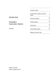
10.4
Direct Stop with Feedback to PLC, Stop Category 1
The application circuit shows a drive control system according to EN ISO 13849-1 PL d, IEC 61508 SIL
2 or EN 954-1 category 3 with PLC and safety module. A PLC performs the process control of the frequency inverter and can start the drive profiles via commands.
If the protective device is actuated, e.g. safety door open, the enable paths of the safety module are
interrupted. At first, the PLC is informed about the fact that the safety function has been triggered.
Then, the PLC decelerates the motor in a controlled way by resetting the direction of rotation (S2 or
S3). After a delay tv, the controller enable signal of the frequency inverter is interrupted via the disconnection of the control voltages from STOA and STOB and the integrated safe pulse block is activated.
The safety module monitors the function of the switches S1 and S2 which are located outside of the
electrical cabinet.
Safety installation
opened
closed
Mains
S1
S2
DC-24 V
Safety control
equipment
tv
PLC
X210A
Acknowledgment
ACTIVE
Cube
1 +E24V
STOA
Start CW
Start CCW
2 GND
3 S1IND
4 S2IND
5 S3IND
6 S4IND
7 S5IND
X210B
STOB
Safety circuit
Speed
Set value
1 S6IND
2 S7IND
3 S1OUTD
4 MFO1A
5 10VRef
6 MFI1A
7 GND
X10
Relay
1 S3OUT.1
Feedback
+24V
2 S3OUT.2
S3OUT
3 S3OUT.3
Eletrical cabinet
M
Position switch displayed actuated
tv: time delay between signaling contact and shutdown contact
ACU-STOV1-01SV2-04 en
09/14
33