1
INDUSTRY PROCESS
AND AUTOMATION SOLUTIONS
Application manual - Positioning
ACTIVE Cube
GB
General Information about the Documentation
This application manual complements the configurations described in the operating
instructions and the „Quick Start Guide“ of the ACU frequency inverters (ACTIVE
Cube series). Configurations 240, 440 and 540, which are described in this application manual, contain additional positioning functions.
For better clarity, the documentation is structured according to the customer-specific
requirements made on the frequency inverter.
Quick Start Guide
The Quick Start Guide describes the basic steps required for mechanical and electrical installation of the frequency inverter. The guided commissioning supports you in
the selection of necessary parameters and the software configuration of the frequency inverter.
Operating Instructions
The Operating Instructions describe and document all functions of the frequency
inverter. The parameters required for adapting the frequency inverter to specific
applications as well as the wide range of additional functions are described in detail.
Application Manual
The application manual supplements the documentation for purposeful installation
and commissioning of the frequency inverter. Information on various subjects connected with the use of the frequency inverter are described specific to the application.
Installation Instructions
Complementing the Brief Instructions and the Operating Instructions, the Installation
Instructions provide information on how to install and use the additional/optional
components.
If you need a copy of the documentation or additional information, contact your local
representative of BONFIGLIOLI.
The following pictograms and signal words are used in the documentation:
Danger!
Danger refers to an immediate threat. Non-compliance with the precaution described
may result in death, serious injury or material damage.
Warning!
Warning refers to a possible threat. Non-compliance with the warning may result in
death, serious injury or material damage.
Caution!
Caution refers to an immediate hazard. Non-compliance may result in personal or
material damage.
Attention!
Attention and the related text refer to a possible behavior or an undesired condition
which can occur during operation.
Note
marks information which facilitates handling for you and supplements the corresponding part of the documentation.
04/08
Application manual Positioning
1
TABLE OF CONTENTS
1
2
General Safety Instructions and Information on Use .................................................. 5
1.1
General Information .............................................................................................. 5
1.2
Purpose of the Frequency Inverters ...................................................................... 6
1.3
Transport and Storage........................................................................................... 6
1.4
Handling and Installation ...................................................................................... 6
1.5
Electrical Connection ............................................................................................. 7
1.6
Information on Use................................................................................................ 7
1.7
Maintenance and Service....................................................................................... 7
System description....................................................................................................... 8
2.1
3
Terminal diagram ACTIVE Cube (ACU) series........................................................ 9
Commissioning of the Frequency Inverter................................................................. 10
3.1
Switching on Mains Voltage ................................................................................ 10
3.2
Commissioning of the motor ............................................................................... 11
3.3 Control Inputs and Outputs................................................................................. 12
3.3.1
Factory settings of the digital inputs ...................................................................... 13
3.4
Digital inputs for speed sensor inputs or for other functions ............................. 15
3.5 Positioning - commissioning procedure .............................................................. 16
3.5.1
Getting started .................................................................................................... 18
3.5.1.1
Motor encoder is position encoder at the same time......................................... 18
3.5.1.2
Two different encoders for motor and positioning ............................................ 19
3.5.1.3
No motor encoder, external encoder for positioning ......................................... 20
3.5.1.4
Consider the operation mode settings for speed sensor input ............................ 20
3.5.2
Reference system ................................................................................................ 21
3.5.3
Setting up a motion profile ................................................................................... 24
3.5.4
Control via software............................................................................................. 25
3.5.5
Write index and read index for the motion blocks table ........................................... 26
4
Operation Modes of the Positioning........................................................................... 28
4.1 General Issues about Operation Modes .............................................................. 28
4.1.1
Assignment of digital inputs.................................................................................. 29
4.1.1.1
Instructions on MFI1D (multifunction input)..................................................... 30
4.1.2
Operation modes for controlling the positioning operation ....................................... 31
4.1.3
Input and output signals ...................................................................................... 33
4.2 Homing ................................................................................................................ 34
4.2.1
Automatic of manual start of homing..................................................................... 34
4.2.2
Input and output signals for homing...................................................................... 35
4.2.3
Homing mode...................................................................................................... 37
4.2.4
Home offset ........................................................................................................ 38
4.2.5
Speed and acceleration of homing operation .......................................................... 38
4.3 Positioning Mode ................................................................................................. 39
4.3.1
Motion block management.................................................................................... 39
4.3.2
VTable ................................................................................................................ 40
4.4 Positioning Mode And Motion Block Data............................................................ 41
4.4.1
Motion Mode ....................................................................................................... 41
4.4.1.1
Motion mode "absolute"................................................................................. 44
4.4.1.2
Motion mode "relative" .................................................................................. 44
4.4.1.3
Motion mode "touch probe" (sensor) .............................................................. 45
4.4.1.4
Motion mode "velocity" .................................................................................. 47
4.4.1.5
Combination with electronic gear.................................................................... 48
2
Application manual Positioning
04/08
4.4.2
Motion block data ................................................................................................ 54
4.4.2.1
Target position.............................................................................................. 54
4.4.2.2
Speed .......................................................................................................... 54
4.4.2.3
Acceleration and Deceleration ........................................................................ 55
4.4.2.4
Automatic sequence of motion blocks (next motion block) ................................ 55
4.4.2.5
Single motion................................................................................................ 62
4.4.3
Control of motion................................................................................................. 63
4.4.3.1
Selection of motion block via digital signals (motion block change-over)............. 63
4.4.3.2
Motion block selection via parameter (starting-record number) ......................... 65
4.4.4
Input and output signals for motion blocks ............................................................ 66
4.4.5
Starting, stopping and resuming ........................................................................... 67
4.4.5.1
Starting and stopping positioning.................................................................... 68
4.4.5.2
Resuming interrupted motion blocks ............................................................... 72
4.4.6
Digital signals for indication of status of motion orders............................................ 73
4.5 JOG Mode............................................................................................................. 76
4.5.1
Fixed speed in JOG mode ..................................................................................... 79
4.5.2
Acceleration and Deceleration in JOG Mode............................................................ 81
4.6
Teach-In (Saving Actual Position as Target Position)......................................... 81
4.7 Electronic gear..................................................................................................... 85
4.7.1
Master position source ......................................................................................... 85
4.7.2
Gear factor.......................................................................................................... 87
4.7.3
Resynchronization................................................................................................ 87
4.7.4
Phasing function .................................................................................................. 87
4.8 Monitoring Functions........................................................................................... 90
4.8.1
Travel limits ........................................................................................................ 90
4.8.2
Hardware limit switches ....................................................................................... 90
4.8.2.1
Hysteresis for hardware limit switch................................................................ 93
4.8.2.2
Fault reaction................................................................................................ 94
4.8.2.3
Move away from HW limit switches................................................................. 95
4.8.3
Software limit switches......................................................................................... 95
4.8.3.1
Move away from SW limit switches ................................................................. 98
4.8.4
Target window .................................................................................................... 99
4.8.5
Contouring error supervision............................................................................... 100
4.8.6
Warning mask Application .................................................................................. 102
4.9
Speed Override .................................................................................................. 104
4.10 Position Comparator .......................................................................................... 105
4.11 Rotary Table Application ................................................................................... 107
4.12 Position Controller ............................................................................................. 110
4.13 Store the actual position value (latching function)........................................... 112
4.14 Wiring Example.................................................................................................. 113
5
List of homing modes............................................................................................... 115
5.1
Brief Description Homing .................................................................................. 115
5.2
Overview Table of Homing Types ...................................................................... 117
5.3
Graphic Overview of Homing Modes ................................................................. 118
5.4
Terminology ....................................................................................................... 119
5.5 Description of Homing Modes............................................................................ 120
5.5.1
Homing Modes with Ref. Signal........................................................................... 121
5.5.2
Homing modes without reference signal .............................................................. 137
5.5.3
Homing modes, only ref. signal and actual position............................................... 150
6
Output Signals and fault messages.......................................................................... 151
6.1
04/08
Actual positioning values................................................................................... 151
Application manual Positioning
3
6.2
Status word of the positioning .......................................................................... 152
6.3
Status word 411 ................................................................................................ 154
6.4
Digital Positioning Output Signals..................................................................... 155
6.5
Logic Signal Sources for Positioning ................................................................. 156
6.6
Positioning Error Messages ............................................................................... 158
6.7
Positioning Warning Status ............................................................................... 162
6.8 Diagnosis and fault clearance............................................................................ 162
6.8.1
Touch probe: Drive is decelerated or stops .......................................................... 163
6.8.2
Drive jerks/is very load....................................................................................... 163
7
Parameter List.......................................................................................................... 164
7.1
Actual Value Menu (VAL) ................................................................................... 164
7.2
Parameter Menu (PARA).................................................................................... 164
7.3
Parameter list, sorted by function ..................................................................... 168
Index .....................................................................................................................................170
4
Application manual Positioning
04/08
1
General Safety Instructions and Information on Use
Warning!
The specifications and instructions contained in the documentation
must be complied with strictly during installation and commissioning.
Only qualified staff who has read the documentation and, in particular,
the safety instructions carefully is allowed to carry out installation or
commissioning work or to operate the frequency inverters. The term
„Qualified Staff“ refers to anybody who is familiar with the installation,
assembly, commissioning and operation of the frequency inverter and
has the proper qualification for the job.
The present documentation was prepared with great care and it was subjected to
extensive and repeated reviews. For reasons of clarity, it was not possible to include
all details of all types of the product in the documentation. Neither was it possible to
consider all conceivable installation, operation or maintenance situations. If you require further information or if you meet with specific problems which are not dealt
with in sufficient detail in the documentation, contact your national BONFIGLIOLI
agent.
We would also like to point out that the contents of this documentation do not form
part of any previous or existing agreement, assurance or legal relationship. Neither
are they intended to supplement or replace such agreements, assurances or legal
relationships. The manufacturer's obligations are exclusively specified in the relevant
purchase contract. This contract also contains all and any warranty regulations which
may apply to the relevant scope of supply. These contractual warranty provisions are
neither extended nor limited by the specifications contained in this documentation.
The manufacturer reserves the right to correct or amend the specifications, product
information and omissions in these operating instructions without notice. The manufacturer shall not be liable for any damage, injuries or costs which may be caused by
the aforementioned reasons.
1.1
General Information
Warning!
04/08
The DC-link circuit of the frequency inverter is charged during operation, i.e. there is always the risk of contact with high voltage. Frequency
inverters are used for driving moving parts and they may become hot at
the surface during operation.
Any unauthorized removal of the necessary covers, improper use,
wrong installation or operation may result in serious injuries or material
damage.
In order to avoid such injuries or damage, only qualified staff may carry
out the transport, installation, setup or maintenance work required. The
standards EN 50178, IEC 60364 (Cenelec HD 384 or DIN VDE 0100),
IEC 60664-1 (Cenelec HD 625 or VDE 0110-1), BGV A2 (VBG 4) as well
as the applicable national regulations must be complied with. The term
„Qualified Staff“ refers to anybody who is familiar with the installation,
assembly, commissioning and operation of the frequency inverter as
well as the possible hazards and has the proper qualification for the job.
Application manual Positioning
5
1.2
Purpose of the Frequency Inverters
Warning!
1.3
The frequency inverters are electrical drive components intended for
installation in industrial plants or machines. Commissioning and start of
operation is not allowed until it has been verified that the machine
meets the requirements of the EC Machinery Directive 98/37/EEC and
EN 60204. In accordance with the CE marking requirements, the frequency inverters also comply with the Low Voltage Directive 72/23/EEC
as well as EN 50178 / DIN VDE 0160 and EN 61800-2. The user shall be
responsible for making sure that the requirements of the EMC Directive
89/336/EEC are met. Frequency inverters are only available at specialized dealers and are exclusively intended for professional use as per EN
61000-3-2.
The frequency inverters are also marked with the UL label according to
UL508c, which proves that they also meet the requirements of the CSA
Standard C22.2-No. 14-95.
The technical data, connection specifications and information on ambient conditions are indicated on the name plate and in the documentation and must be complied with in any case. Anyone involved in any
kind of work at the device must have read the instructions carefully and
understood them before starting the work.
Do not connect any capacitive loads.
Transport and Storage
The frequency inverters must be transported and stored in an appropriate way. During transport and storage the devices must remain in their original packaging. The
units may only be stored in dry rooms which are protected against dust and moisture and are exposed to little temperature deviations only. Observe the climatic conditions according to EN 50178 and the marking on the packaging. The frequency
inverters must not be stored for more than one year without connecting them to
nominal voltage.
1.4
Handling and Installation
Warning!
Damaged or destroyed components must not be put into operation
because they may be a health hazard.
The frequency inverters are to be used in accordance with the documentation as
well as the applicable directives and standards. They must be handled carefully and
protected against mechanical stress. Do not bend any components or change the
isolating distances. Do not touch electronic components or contacts. The devices are
equipped with components which are sensitive to electrostatic energy and can easily
be damaged if handled improperly. Any use of damaged or destroyed components
shall be considered as a non-compliance with the applicable standards. Do not remove any warning signs from the device.
6
Application manual Positioning
04/08
1.5
Electrical Connection
Warning!
Before any assembly or connection work, discharge the frequency inverter. Verify that the frequency inverter is discharged.
Do not touch the terminals because the capacitors may still be charged.
Comply with the information given in the operating instructions and on
the frequency inverter label.
When working at the frequency inverters, comply with the applicable standards BGV
A2 (VBG 4), VDE 0100 and other national directives. Comply with the electrical installation instructions given in the documentation as well as the relevant directives.
The manufacturer of the industrial machine or plant is responsible for making sure
that the limit values specified in the EMC product standard EN 61800-3 for electrical
variable-speed drives are complied with. The documentation contains information on
EMC-conforming installation. The cables connected to the frequency inverters may
not be subjected to high-voltage insulation tests unless appropriate circuitry measures are taken before.
1.6
Information on Use
Warning!
1.7
Maintenance and Service
Warning!
04/08
The frequency inverter may be connected to power supply every 60 s.
This must be considered when operating a mains contactor in jog operation mode. For commissioning or after an emergency stop, a nonrecurrent, direct restart is permissible.
After a failure and restoration of the power supply, the motor may start
unexpectedly if the AutoStart function is activated.
If staff is endangered, a restart of the motor must be prevented by
means of external circuitry.
Before commissioning and the start of the operation, make sure to fix
all covers and check the terminals. Check the additional monitoring and
protective devices according to EN 60204 and applicable the safety
directives (e.g. Working Machines Act, Accident Prevention Directives
etc.).
No connection work may be performed, while the system is in operation.
Unauthorized opening and improper interventions can lead to personal
injury or material damage. Repairs on the frequency inverters may only
be carried out by the manufacturer or persons authorized by the manufacturer. Check protective equipment regularly.
Application manual Positioning
7
2
System description
Positioning via motion blocks enables movement by a certain distance or to a target
position. For each motion block, a separate motion profile can be set, including
speed, acceleration and deceleration ramp. When motion blocks are processed automatically, the drive will react according to the parameterized behavior when it
reaches the target position.
Scope of functions
−
−
−
−
−
−
−
−
−
−
−
−
−
−
−
Positioning of linear and round axes
Optimized round axes positioning (shortest way)
Absolute and relative positioning
Touch probe positioning for evaluation of sensors, e.g. motion as from this point
Specification of values and parameter configuration can be done via user-defined
scale (user units)
32 motion blocks for different target positions and motion profiles
Automatic motion block sequence, event or time controlled
Repetition of motion blocks
Teach-in function for taking over the actual position value as the target position
in the motion block
JOG mode for manual operation via digital inputs
Combination of positioning with electronic gear
Different homing modes for determining the reference point for positioning
Control via digital inputs or communication module
Monitoring: Position monitoring via target window, contouring error monitoring,
hardware and software limit switches
Parameter configuration via commissioning and diagnosis software VPlus
Components required
Frequency inverter ACU (ACTIVE Cube),
Incremental encoder or resolver,
Suitable extension module,
Interface adapter KP232 for port (A),
Commissioning and diagnosis software VPlus, version 4 or
higher
(A)
(A)
Optional Components
Communication modules (1 option possible),
Port (B):
CM-232 with RS232 interface,
CM-485 with RS485 interface,
CM-PDP-V1 with Profibus–DP-V1 interface,
CM-CAN with CANopen interface
(B)
(B)
Epansion modules (1 option possible), port (C):
EM-ENC for detailed evaluation of incremental encoder (TTL
to RS-422A/RS-485 or HTL, DC 5 to 30 V),
EM-IO for additional analog and digital outputs; depending on
module, system bus interface available, too,
EM-RES for resolver evaluation; depending on module, system bus interface available, too,
EM-SYS for communication via system bus
(C)
8
Application manual Positioning
(C)
04/08
2.1
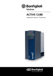
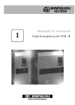
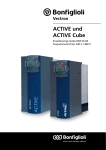
Terminal diagram ACTIVE Cube (ACU) series
The terminal diagram shows an example of a linear axis, with standard parameter
configuration of digital inputs. The sensor is evaluated using an EM extension module.
ACTIVE Cube
RS232
VPlus
S2IND
S3IND
S4IND
S5IND
S6IND
S7IND
S1OUTD
MFO1A
10VRef
MFI1D
GND
U V W
S1IND
X2
GND
EM
X410A X410B
X210B
+20V
X210A
1
2
3
4
5
6
7
1
2
3
4
5
6
7
SMFI1D
S5
STOB
STOA
S2 S3
S6
S4
Terminal diagram ACTIVE Cube (ACU) series
: clockwise;
Switch
STOA
STOB
S2
S3
S4
S5
S6
SMFI1D
: Anticlockwise
Function
Wire input S1IND as shut-down path STOA of safety function STO 1)
Wire input S1IND as shut-down path STOB of safety function STO 1)
Start positioning or clockwise operation in JOG mode
Stop positioning or anticlockwise operation in JOG mode
Limit switch for limitation of motion range in positive direction 2)
Limit switch for limitation of motion range in negative direction 2)
Home switch for homing, point of reference for absolute positioning
Change-over between positioning mode and JOG mode (JOG mode in
manual mode)
1)
Safety function STO (Safe Torque Off) is wired through two channels via inputs STOA and
STOB. This safety function is described in user manual "Safe Torque Off". The "Safe Torque
Off" user manual must be complied with when using the "Safe Torque Off" function.
2)
Different from the factory setting. Assign S4IND and S5IND to the parameters for HW limit
switches. Set Parameter Operation mode 490 of speed sensor 1 to „0 - Off“.
04/08
Application manual Positioning
9
3
Commissioning of the Frequency Inverter
Warning!
3.1
Carry out the electrical and mechanical installation according to the
operating instructions or the "Quick Start Guide" of the frequency inverter. Comply with the safety instructions provided there.
Frequency inverters of the ACU series feature the "Safe Torque Off"
function. In any case comply with the application manual "Safe Torque
Off" when using this safety function.
Switching on Mains Voltage
After completion of the installation work, make sure to check all control and power
connections again before switching on the mains voltage. If all electrical connections
are correct, make sure that the frequency inverter is not enabled. After power-up,
the frequency inverter carries out a self-test and the relay output (X10) reports
"Fault".
Switch off release of frequency inverter:
Control inputs S1IND (STOA) and S7IND (STOB) open
After a few seconds, the self-test is complete, the relay (X10) picks up and signals
"no fault ".
If the unit is in "as-delivered" condition or after resetting the unit to the factory settings, the guided commissioning procedure is started automatically. On the control
unit, the “SetUP“ menu from the menu branch CTRL is displayed.
10
Application manual Positioning
04/08
3.2
Caution!
Commissioning of the motor
During the guided commissioning, comply with the safety instructions in
chapter "General Safety Instructions and Information on Use" and in
the Operating Instructions or the "Quick Start Guide" of the frequency
inverter.
Carry out the guided commissioning procedure of the frequency inverter for one of
the configurations listed below. These configurations contain the motion block positioning functions.
Note:
The guided commissioning contains the function for parameter identification. The parameters are determined by way of measurement and set
accordingly. In the case of higher requirements as regards the accuracy
of the speed/torque control, you should carry out the guided commissioning procedure once again under operating conditions because
part of the machine data depends on the operating temperature.
Configuration 240, field-orientated control with positioning
Configuration 240 extends the field-oriented control of an asynchronous machine by
the positioning functions.
The motor controller and the position controller can use the same encoder (motor
encoder) or different encoders (motor encoder and position encoder).
Configuration 440, sensorless field-orientated control with positioning
Configuration 440 extends the sensorless field-oriented control of an asynchronous
machine by the positioning functions.
The motor is controlled without sensors. The positioning controller can be used via
any encoder input.
Configuration 540, field-orientated control of synchronous machine with
positioning
Configuration 540 extends the field-oriented control of a synchronous machine by
the positioning functions. Extension module EM-RES with resolver interface are required for this.
The motor controller and the position controller can use the same encoder (motor
encoder) or different encoders (motor encoder and position encoder).
04/08
Caution!
To enable control of a synchronous machine in configuration 540, parameter Offset 382 must be set before the guided commissioning. To
do this, proceed according to the operating instructions for the extension module EM-RES installed. Otherwise, personal or machine damage
may occur.
Note:
For first commissioning, the drive can be controlled manually, using the
JOG function, via the "FUN" key or the digital inputs.
The processing speed of automatic motion block sequence can be reduced for commissioning. To do this, use the speed override function.
Note:
The motor encoder should only be used for motor and position control
in slip-free systems (e.g. linear spindle). In systems where slip may
occur (e.g. wheel/rail systems) always use a position encoder to obtain
optimum results.
Application manual Positioning
11
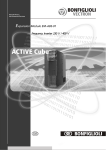
3.3
Control Inputs and Outputs
The modular structure of the frequency inverters enables a wide spectrum of applications on the basis of the available hardware and software functionality. The functionality of the control inputs and outputs described in the "Quick Start Guide" and
operating instructions is extended in the described configurations.
Caution!
Switch off power supply before connecting or disconnecting the control
inputs and outputs. Verify that the keyed control inputs and outputs are
deenergized before connecting or disconnecting them. Otherwise, components may be damaged.
The unit may only be connected with the power supply switched off.
Make sure that the frequency inverter is discharged.
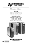
ACU frequency inverters of ACTIVE Cube series
X210A.1
X210A.2
X210A.3
X210A.4
STOA
+
-
B
A
Z
STOB
X210A
1 +20 V / +24 V ext.
2 GND 20 V / GND 24 V ext X210A.5
3 S1IND
4 S2IND
5 S3IND
6 S4IND
X210A.6
7 S5IND
X210B
1 S6IND
2 S7IND
3 S1OUT
4 MFO1A
5 +10 V/4 mA
6 MFI1D
7 GND 10 V
X210A.7
X210B.1
X210B.2
X210B.3
X210B.4
X210B.5
X210B.6
X210B.7
1)
2)
3)
4)
Control terminal X210A
+20 V voltage output (Imax=180 mA) or
input for external power supply 24 V
GND 20 V/ GND 24 V (ext.)
Safety function, digital input STOA
− Start Positioning
− JOG Clockwise
− Store actual position value (latching)
− Stop Positioning
− JOG Anticlockwise
− Touch probe
Encoder 1 Track B 1) or
freely programmable 2)
Encoder 1 Track A 1) or
freely programmable 2)
Control terminal X210B
Home switch 3) or
Encoder 1 Zero Track Z 4)
Safety function, digital input STOB
Operating message
Analog signal of actual frequency
Supply voltage +10V
− Change-over position control/JOG
mode (JOG mode active)
− Teach-In-Signal
Ground 10 V
Factory setting in configuration 240
If no speed sensor is connected to S4IND/S5IND the digital inputs can be used freely programmable (e.g. for hardware limit switches).
Factory setting in configurations 240, 440 and 540
For evaluation of an encoder zero track an Operation Mode 490 for speed sensor 1 higher than
1000 must be selected. Linking of other functions to this input are not active.
The connection diagram describes the default assignment of control terminals and
functions in the different configurations positioning control. According to the requirements of the application, the other functions can be assigned to the control
terminals.
Note:
12
In order to fully use the positioning functions, an optional extension
module is required. This module enables, for example, encoder evaluation, motion-block change-over or reference percentage change-over.
Application manual Positioning
04/08
3.3.1
Factory settings of the digital inputs
Control input functions
Digital
Control
Control positioning
JOG mode /
Input
terminal
Teach-in
Digital inputs of frequency inverter:
S1IND
X210A.3
Digital input STOA for safety function
S2IND
X210A.4
Start
Store actual
JOG Clockwise
Positioning
position value 3)
JOG Anticlockwise
S3IND
X210A.5
Stop Positioning,
Touch probe 1)
S4IND
X210A.6
Freely programmable or 2)
Encoder 1 Track B
S5IND
X210A.7
Freely programmable or 2)
Encoder 1 Track A
S6IND
X210B.1
Home switch or
2)
Encoder 1 Zero Track Z
X210B.2
Digital input STOB for safety function
MFI1D
X210B.6
Change-over position conTeach-in signal in teachtrol/JOG mode (JOG mode acin mode
tive)
Digital inputs extension module:
EM-S1IND depending Motion Block Change-Over 1
on module Alternative: - Encoder 2 Zero Track Z
- Fixed frequency change-over 1
- Fixed percentage value change-over 1
EM-S2IND
Motion Block Change-Over 2
Alternative: - Encoder 2 Track A
- Fixed frequency change-over 2
- Fixed percentage value change-over 2
EM-S3IND
Motion Block Change-Over 3
Alternative: - Encoder 2 Track B
1)
Comply with the notes in section 4.4.1.3.
2)
Dependent on the settings of parameters Configuration 30 and Operation
Mode 490. See chapter 3.5.1.4.
3)
Switch on the function via parameter Operation Mode 1280. Comply with the
notes in section 4.13.
Control terminal/
Identification
X210A.4
Start Positioning
Description
The input is assigned to parameter Start Positioning 1222.
When activated, the Starting-Record Number 1228 or another
motion block selected by the motion block change-over function
is started.
The motion blocks can be switched via digital inputs EM-S1IND,
EM-S2IND and EM-S3IND of an extension module.
JOG Clockwise
In JOG mode, the drive is moved in positive direction (clockwise)
at an adjustable fixed speed. JOG mode is activated via terminal
X210B.6. In teach-in operation modes (Operation Mode 1221),
the JOG function is activated automatically.
Store actual position
value
The function can be switched on via parameter Operation Mode
1280. With signal edge the actual position value is stored in the
EEPROM and displayed via Latched Position 1281.
04/08
Application manual Positioning
13
X210A.5
Stop Positioning
JOG Anticlockwise
In JOG mode, the drive is moved in negative direction (anticlockwise) at an adjustable fixed speed. JOG mode is activated
via terminal X210B.6. In teach-in operation modes (Operation
Mode 1221), the JOG function is activated automatically.
Touch probe
Input for momentary contact switch or sensor for setting the
reference position. Effective in Motion Mode 1208 with touchprobe. Rising or falling edge (depending on setting of Motion
Mode 1208) on input sets the point of reference at the current
position. As soon as the signal is received, the drive moves by
the relative distance of parameter Target Position/Distance
1202. Parameter configuration for digital signal "Stop Positioning" should be changed when touch probe mode is used.
X210A.6
Encoder 1
Input Encoder 1 Track B, HTL, DC 12 … 30 V
or freely programmable
Evaluation of parameterized functions if the terminal is not used
as encoder input.
Possible function:
Pos. HW Limit Switch
Input for positive hardware limit switch. Limitation of travel range
in positive direction. The drive reacts according to parameter
Fault Reaction 1143 when the switch is reached. Positive direction (clockwise direction) is disabled.
Set parameter Pos. HW Limit Switch 1138 = “540 - S4IND inverted (Hardware)“. Set Parameter Operation Mode 490 of
speed sensor 1 = “0 - Off”. If X210A.6 is used as encoder input
the HW limit switch function is not evaluated as this input.
X210A.7
Encoder 1
Input Encoder 1 Track A, HTL, DC 12 … 30 V
or freely programmable
Evaluation of parameterized functions if the terminal is not used
as encoder input.
Possible function:
Neg. HW Limit Switch
Input for negative hardware limit switch. Limitation of travel
range in negative direction. The drive reacts according to parameter Fault Reaction 1143 when the switch is reached. Negative direction (anticlockwise direction) is disabled.
Set parameter Neg. HW Limit Switch 1137 = “541 - S5IND inverted (Hardware)“. Set Parameter Operation Mode 490 of
speed sensor 1 = “0 - Off”. If X210A.7 is used as encoder input
the HW limit switch function is not evaluated as this input.
X210B.1
Home switch
or Encoder 1
14
The drive stops at the current position at deceleration ramp set in
Deceleration 1206.
Input for reference cams. Marks the point of reference for absolute positioning. Via parameter Home Switch 1139, the logic
status of the switch is evaluated.
Input Encoder 1 Zero Track Z, HTL, DC 12 … 30 V.
Select one of the settings 1001 … 1132 (with reference pulse) for
parameter Operation Mode 490.
Application manual Positioning
04/08
X210B.6
JOG-Mode Active
Teach-In
3.4
Activates JOG mode. JOG clockwise via terminal X210A.4 or JOG
anticlockwise via terminal X210A.5 is executed.
In teach-in operation modes (Operation Mode 1221), the JOG
function is activated automatically.
When a rising signal edge is received, the current position in the
selected motion block is saved as the target position.
The motion block is selected by parameter Starting-Record Number 1228 or the motion block change-over function (parameters
1224 to 1227 and 1254).
The function is activated via Operation Mode 1221.
Parameter Teach-In-Signal 1239 must be assigned the digital
input signal or the logic signal which is to trigger saving of the
actual position.
Digital inputs for speed sensor inputs or for other functions
The setting of parameter Operation Mode 490 of speed sensor 1 affects the processing of
functions which are linked to the digital inputs S4IND, S5IND and S6IND:
− In the settings 1 … 132 for Operation Mode 490 the digital inputs S4IND and S5IND are
prepared for speed sensor inputs.
− In the settings 1001 … 1132 for Operation Mode 490 the digital inputs S4IND, S5IND and
S6IND are prepared for speed sensor inputs.
The setting of the digital inputs as speed sensor inputs (1 … 1132 for Operation Mode 490)
has higher priority than the control of other functions via these inputs. Other functions will not
be evaluated.
Set Operation Mode 490 to “0 - Off” if S4IND, S5IND and S6IND shall not be used as speed
sensor inputs but for control of other functions via these inputs.
Selection for
Operation Mode 490
0
1 … 132
1001 … 1132
S4IND, S5IND and S6IND as
speed sensor inputs or for other functions
Functions which are assigned to the digital inputs S4IND, S5IND and
S6IND will be evaluated. The digital inputs S4IND, S5IND and S6IND
are not prepared as speed sensor inputs.
The digital inputs S4IND and S5IND are prepared as speed sensor inputs. Other functions which are assigned to the inputs S4IND and
S5IND will not be evaluated.
The digital inputs S4IND, S5IND and S6IND are prepared as speed sensor inputs. Other functions which are assigned to the inputs S4IND,
S5IND and S6IND will not be evaluated.
For the settings of speed sensor inputs also refer to section 3.5.1.
04/08
Application manual Positioning
15
3.5
Positioning - commissioning procedure
Terminal assignment:
S1IND (STOA) and S7IND (STOB): LOW signal
S2IND (Start positioning): LOW signal
S3IND (Stop positioning): LOW signal
S4IND and S5IND: encoder track B and track A or for parameterized function
S6IND: home switch or encoder zero track Z
MFI1D (JOG mode): LOW signal
Commissioning of frequency inverter:
Comply with chapter "Commissioning of Frequency Inverter",
set up configuration 240, 440 or 540,
switch on power supply,
start commissioning and diagnosis program VPlus (if not yet done for commissioning),
Set up reference system (motion distance per rotation of drive and gear factor),
Select suitable homing mode,
Select encoder source for positioning
For manual mode (JOG mode):
Set up parameters for JOG mode or use factory settings,
Release with HIGH signal on S1IND (STOA) and S7IND (STOB),
Activate JOG mode with HIGH signal at MFI1D, clockwise via S2IND, anticlockwise
via S3IND, perform function test
Entering motion profile:
In VPlus, set up the parameters of the motion blocks,
switch on speed override, in order to position at reduced speed during commissioning.
Start positioning:
Check readiness for operation: when green LED is flashing: ready for operation; if
green and red LED are flashing: ready for operation and warning message is present, repair fault,
Release with HIGH signal on S1IND (STOA) and S7IND (STOB) and start of positioning with HIGH signal on S2IND
For communication via field bus or system bus: Set up other parameters according
to operating instructions of the corresponding extension or communication module.
Motion blocks
The motion profile is defined in motion blocks, indicating the target position, speed
and acceleration. A positioning operation may comprise a maximum of 32 motion
blocks.
Discrete selection: Each of the 32 motion blocks can be selected both via logic signals and parameters (also for transfer via field bus or system bus).
Cycle: The motion blocks can be repeated or processed in a freely programmable
order.
In the motion blocks, the motion block to be processed next can be identified.
The next motion block can be activated:
- by events, e.g. via digital inputs or logic signals
- after a definable delay
In the motion block, the motion mode is selected: absolute (referred to a fixed reference position), relative (to moving distance, referred to last position approached)
or "Touch Probe" (to moving distance, referred to a sensor signal on digital input
S3IND).
16
Application manual Positioning
04/08
Digital signals for status indication
Digital signals can be influenced depending on the status of a motion order. For
example, a digital signal can be parameterized such that it signals reaching of the
target position or the end of the motion block.
JOG mode
The drive is operated manually via two digital inputs at a parameterizable, fixed
speed. This enables for example functional tests for commissioning and approaching
of positions for teach-in mode.
Teach-In
With this function, any position approached can be entered directly in a motion
block as a target position. The required position can be approached in JOG mode.
The current position value is saved as the target position when an increasing edge
is present on the teach-in terminal.
Homing
To determine the drive speed and position, the frequency inverter captures the signals from position sensors such as incremental encoders or resolvers. When the
frequency inverter is switched on, there is no relation between the position sensor
and the mechanical position of the axis. In order to determine an absolute point of
reference (reference position) for the positioning operation, a homing operation
must be performed. All absolute position data is referred to this reference position.
By selecting a certain homing mode, you can define in which direction the reference
position is to be found and which type of switch (limit switch, home switch) is used.
In the homing operation, the drive moves to the reference position and stops there.
Monitoring
To limit the motion range and protect the machine, limit switches are connected to
the digital input terminals of the frequency inverter. The behavior of the drive when
reaching the limit switches is parameterizable (e.g. error switch-off, shut down).
Software limit switches enable monitoring of the permissible motion range. Positioning commands will be executed only within the range defined by parameters. The
software limit switches are active only after a successful homing operation.
The adjustable target window monitors the current position after performance of a
positioning operation. Reaching of the required position is signaled only if the current position is within the target window.
The contouring error monitoring function monitors the maximum permissible deviation of the current position and the required position. This monitoring function determines how accurately the positioning operation must be performed.
04/08
Application manual Positioning
17
3.5.1
Getting started
In order to use the positioning function, you must start the frequency inverter in
Configuration 240, 440 or 540. If required, perform a motor measurement. Several
functions will be readjusted as soon as you set up the configuration of the positioning operation. This includes the functions of the digital inputs.
Warning!
Ensure that your parameterization corresponds to the connected terminals.
For commissioning, you must select different configurations for the following cases:
Case
1
2
3
3.5.1.1
Description
Motor encoder is position encoder at the
same time
Two different encoders for motor and
positioning
No motor encoder, external encoder for
positioning
Possible Configuration 30
240, 540
240, 540
440
Motor encoder is position encoder at the same time
In slip-free systems, the motor encoder can be used as position encoder at the same
time. By using one encoder for both functions, the overall costs can be reduced.
Configuration 30 = 240 | 540, motor encoder = position encoder
Encoder 1
Encoder 2
Motor controller
Operation Mode
Operation Mode
Actual Speed Source 766
490
493
Division Marks
Division Marks
491
494
Actual Position Source 1141 =
“0 - As P. 766 Actual Speed Source”
Level 495
In the corresponding parameters, set up the properties of the encoders according to
the wiring of Encoder 1 or Encoder 2. The parameters of Encoder 2 are available
only if the corresponding extension module is connected.
Adjust parameter Actual Speed Source 766 to connected encoder.
Adjust parameter Actual Position Source 1141 to "0 - As P. 766 Actual Speed
Source" (corresponds to factory settings).
18
Application manual Positioning
04/08
3.5.1.2
Two different encoders for motor and positioning
In systems where slip may occur, the motor encoder cannot be used as position
encoder at the same time. Due to the slip (e.g. slipping in the case of a wheel/rail
system), the motor encoder cannot approach the actual target with sufficient accuracy. By using a position encoder connected to the positioning system, precise positioning is possible even in the case of a system where slip may occur. The corresponding configurations are described in the following tables. In any case, you will
need a suitable extension module for evaluation of Encoder 2.
Note:
If both a motor and a position encoder are used, the function "Electronic Gear" cannot be used.
Encoder 1 is motor encoder
Encoder 2 is position encoder
Configuration 30 = 240 | 540, motor encoder, position encoder
Encoder 1
Encoder 2
Motor controller
Position controller
Operation mode Operation mode Actual Speed Source
490
493
Division Marks
Division Marks
491
494
766 =
"1 – Speed Sensor 1"
Actual Position
Source 1141 =
"2 – Speed Sensor 2"
Level 495
Encoder 1 is position encoder
Encoder 2 is motor encoder
Configuration 30 = 240 | 540, position encoder, motor encoder
Encoder 1
Encoder 2
Motor controller
Position controller
Operation mode
490
Operation
mode 493
Division Marks
Division Marks
491
494
Actual Speed Source
766 =
"2 – Speed Sensor 2"
Actual Position
Source 1141 =
"1 – Speed Sensor 1"
Level 495
In the corresponding parameters, set up the encoders parameters according to the
properties of Encoder 1 or Encoder 2. The parameters of Encoder 2 are available
only if the corresponding extension module is connected.
Adjust parameter Actual Speed Source 766 to connected motor encoder. The external encoder is evaluated via parameter Actual Position Source 1141.
04/08
Application manual Positioning
19
3.5.1.3
No motor encoder, external encoder for positioning
In some applications the speed control accuracy and the dynamic behaviour of a
sensorless motor control are sufficient. Positioning is possible in non-slip and in slipcontaining systems via an external encoder.
Configuration 30 = 440, only position encoder
Encoder 1
Encoder 2
Motorregler
Position controller
Operation mode
Operation mode
490
493
Actual Speed
Source 766 = 3 -
Actual Position
Source 1141 =
Machine Model
Division Marks
Division Marks
491
494
"1 - Speed Sensor 1"
or "2 - Speed Sensor
2", depending on
the application
Level 495
Set the encoder behaviour in the correlative parameters for speed sensor 1 and
speed sensor 2. The speed sensor 1 parameters are only available if an expansion
module with speed sensor input is installed.
3.5.1.4
Consider the operation mode settings for speed sensor input
The digital input signals S4IND, S5IND and S6IND can set as signal sources in all
configurations (parameter Configuration 30).
− In parameter settings Operation Mode 490 > 0 the inputs S4IND and S5IND are
evaluated only as speed sensor inputs. Other functions at these inputs are not
evaluated.
− In parameter settings Operation Mode 490 > 1000 additional the input S6IND is
evaluated as speed sensor track. Other functions at this input are not evaluated.
Digital
inputs
S4IND
S5IND
S6IND
20
Operation Mode 490 =
1001 … 1132
1 … 1000
0
Speed sensor 1 track B
Free programmable
Speed sensor 1 track A
Free programmable
Speed sensor 1 track Z
Home switch
Application manual Positioning
04/08
3.5.2
Reference system
The reference system provides the link between the electrical system and the mechanical system. In parameter Feed Constant 1115, the user units (u) per revolution
(U) are entered. By choosing a suitable parameter configuration, the feed constant
can consider both the mechanical motion distance and the accuracy (resolution) (see
example).
Via Gear Box: Driving shaft revolutions 1116 and Gear Box: Motor shaft revolutions 1117, it is possible to consider the transmission ratio of a gearbox.
The terms Gear Box: Driving shaft revolutions 1116 and Gear Box: Motor shaft
revolutions 1117 are used in compliance with CANopen Standard CiA402 Device
Profile Drives and Motion Control.
Parameter
No.
Description
1115 Feed constant
Gear Box: Driving shaft revolu1116
tions
1117 Gear Box: Motor shaft revolutions
Min.
1 u/U
Settings
Max.
Fact. sett.
231-1 u/U
65536 u/U
1
65 535
1
1
65 535
1
Maximum motion distance
The internal representation of position values is limited to ±231-1 increments, referred to a resolution of 216 increments/revolution. The maximum motion distance
smax depends on the settings of parameters Feed Constant 1115, Gear Box: Driving
shaft revolutions 1116 and Gear Box: Motor shaft revolutions1117. At a higher
accuracy of the feed constant and gear factor, the maximum motion distance is reduced.
[]
s max u =
(
± 2
31
)
− 1 Ink ⋅ Feed Constant 1115
[u ] ⋅ Gear Box : Driving shaft revolutions 1116
U
Ink
2
⋅ Gear Box : Motor shaft revolutions 1117
U
16
04/08
Application manual Positioning
21
Example: Linear axis, drive via gearbox
Revolutions of gearbox output shaft
Gear Box: Driving shaft revolutions 1116
Gear
Feed
Gear Box: Motor shaft revolutions 1117
Revolutions of motor shaft
Feed rate of linear axis: 25 mm per revolution of the output shaft
Required positioning accuracy: ±1/100 mm
Gear factor: 1/19.75
Feed rate
25 mm
=
= 2500
Accuracy 1/100 mm
Feed Constant =
1 unit = 0.01 mm
Set Feed Constant 1115 to 2500 u/U.
Gear factor =
Gear Box : Shaft revolutions 1116
1
100
=
=
19.75 Gear Box : Motor revolutions 1117 1975
Set Gear Box: Driving shaft revolutions 1116 to 100.
Set Gear Box: Motor shaft revolutions1117 to 1975.
s max [u] =
(
)
± 2 31 − 1 Ink ⋅ 2500
16
2
[u] ⋅ 100
Ink
⋅ 1975
U
U
= ±4 187 848 units ≈ ±41 878 mm ≈ ±41.9 m
Example: Rotary table
Revolutions of rotary table
Gear Box: Driving shaft revolutions 1116
Revolutions of motor shaft
Gear Box: Motor shaft revolutions 1117
Turning angle (feed) of rotary table: 360°
Required positioning accuracy: ±1/10 °
Gear factor (Ratio of belt drive
wheel diameters): 2.45 m/0.18 m
Feed Constant =
Feed rate
360°
=
= 3600
Accuracy 1/10 °
Set Feed Constant 1115 to 3600 u/U.
22
Application manual Positioning
04/08
Gear Factor =
2.45
0.18
=
Gear Box : Driving shaft revolutions 1116
Gear Box : Motor shaft revolutions 1117
=
245
18
Set Gear Box: Driving shaft revolutions 1116 to 245.
Set Gear Box: Motor shaft revolutions1117 to 18.
s max [u] =
Note:
(
)
± 2 31 − 1 Ink ⋅ 3600
16
2
Ink
⋅ 18
U
[u] ⋅ 245
U
= ±1 605 631 999 units ≈ ±160 563 200° ≈ ±446 009 U
Gear transmission factors are rounded in many cases and may result in
a "drift" in the application, i.e. due to the rounded values, the deviation
between the actual position and the required position increases with
each revolution. This particularly affects rotary table applications which
turn in one direction continuously because their position change continues to increase all the time. Use exact gear transmission factors in
order to eliminate this drift. The exact gear transmission factor can be
calculated from the number of teeth of the individual gearwheels.
Example: Calculation of gear factors
Example: Three-stage gearbox
(i = 67.7 rounded) at reduction
gearing of 3:1.
Number of teeth:
D1 = 13
D2 = 25
D3 = 12
D4 = 27
D5 = 11
D6 = 31
V1 = 1
V2 = 3
D2 D3 D6
M
D1
A
V1
D4 D5
V2
M: motor side, A: output side, V: reduction
gearing
04/08
Gear Box: Driving shaft revolutions 1116
= D2 x D4 x D6 x V2
= 25 x 27 x 31 x 3 = 62775
Gear Box: Motor shaft revolutions 1117
= D1 x D3 x D5 x V1
= 13 x 12 x 11 x 1 = 1716
Application manual Positioning
23
3.5.3
Setting up a motion profile
For complex motion profiles, e.g. profiles requiring different speeds and accelerations, different motion blocks must be created.
Example:
v
Motion block 1
v1
v2
a11
Motion block 2
a12
a21
a22
t2
v3
Motion block 1
Approach target pos. 1
a11 Acceleration
v1 Speed
a12 Deceleration
Motion block 2
Approach target pos. 2
a21 Acceleration
v2
Speed
a22 Deceleration
t2
Delay until next motion
block, e.g. for workpiece machining
Motion block parameters
Target Position / Distance 1202
Speed 1203
Acceleration 1204
Deceleration 1206
Delay 1212
Delay: Next Motion Block 1213
Event 1 1214
Event 1: Next Motion Block 1214
Motion block 3
a31
Motion
Return
a31
v3
a32
a32
t
block 3
Acceleration
Speed
Deceleration
In example above:
s1, s2, s3
v1, v2, v3
a11, a21, a31
a12, a22, a32
t2
3 (motion block 2)
6 – On (motion block 1)
2 (motion block 1);
0 (motion block 3);
The motion profile shown in the example requires parameterization of 3 motion
blocks.
24
Application manual Positioning
04/08
3.5.4
Control via software
All parameters of the frequency inverter can be set up via the PC software VPlus. In
Configuration 30, set up an operation mode x40 which is suitable for positioning.
Now, when data are read from the inverter, all parameters are read and are available for parameterization.
With the PC software VPlus, 32 motion blocks with different motion profiles are
available. The program VTable which is included in VPlus enables comfortable parameterization of the motion blocks. The program can be started via menu entry "Start
Positioning" or the "Positioning Function" icon. VTable represents the 32 motion
blocks arranged in columns, which provides better clarity. Via index 0, values can be
changed for all motion blocks at the same time. This can be used, for example, to
change the speed in all motion blocks quickly and comfortably.
04/08
Application manual Positioning
25
3.5.5
Write index and read index for the motion blocks
table
Via the write and read indices, the index of the motion block table the parameters of
which are to be read or written is specified. VTable uses the parameters automatically for writing and reading. The write and read parameters are required for parameterization via keypad or for parameterization via a bus system (e.g. PROFIBUS).
Parameterize and read motion blocks with write index and read index via
software VPlus
The motion blocks can be parameterized in the user interface VPlus or in the motion
block table VTable. In the user interface VPlus, an index of the motion block table
can be set via parameter Motion Block Sel. (Writing) 1200. The chosen index corresponds to a column in the motion block table. The settings of parameters 1202 to
1219, 1247 and 1248 are taken over in the selected index of the motion block
table. Via parameter Motion Block sel. (Reading) 1201, the values of a selected
index can be read from the motion block table.
No.
1200
1201
1)
Parameter
Description
Motion Block Sel. (Writing)
Motion Block Sel. (Reading)
Min.
0
0
Settings
Max.
Fact. sett.
65 1)
1
1)
65
1
Setting defines the place where motion blocks are saved.
Settings for fixed parameterization
(non-volatile):
0: all motion blocks in EEPROM
1 … 32: individual motion blocks in EEPROM
Note:
Settings only required for parameterization via
communication interface (volatile):
33: all motion blocks in RAM
34 … 65: individual motion blocks in RAM
The settings"0" and "33" for Motion Block Sel. (Writing) 1200 change
all motion blocks in EEPROM and RAM.
In the case of non-volatile storage (0…32), the changed values are still available
when power supply is switched on again.
In the case of volatile storage (33…65), the data is only stored in RAM. If the unit is
switched off, this data is lost and the data required are loaded from EEPROM after
restart.
Definition:
Motion block RAM = Motion block EEPROM +33
26
Application manual Positioning
04/08
Write index/Motion Block Sel. (Writing) 1200,
Read index/Motion Block Sel. (Reading) 1201
VPlus
Parameter
Motion Block Sel. (Writing) 1200
Motion Block Sel. (Reading) 1201
Target Position / Distance 1202
Speed 1203
.
.
Data Set 0
2
2
4096 units
20000 u/s
...
...
...
VTable
Motion Blocks ...
Target Position / Distance 1202
Speed 1203
.
.
04/08
Application manual Positioning
Index 1
...
...
...
...
Index 2
4096 units
20000 u/s
...
...
27
4
4.1
Operation Modes of the Positioning
General Issues about Operation Modes
The following operation modes are available for positioning. Operation modes:
− Positioning mode. Automatic operation for sequence-controlled and repeatable
approach to different targets in an application. The target can be selected via an
overriding controller (parameter channel of field bus or digital inputs).
− Homing. A homing operation is performed in order to define a new point of reference in the system. After a homing operation, the identified point of reference
is used as the basis of all positioning operations.
− JOG mode. This operation mode enables free moving via digital inputs. This
mode is often used for setup or service purposes.
− Teach-in mode. Teach-in mode is normally used only during first commissioning
of a plant or after the plant has been retrofitted. In this mode, a current position
can be saved for a motion block in the frequency inverter.
"Positioning Mode" and "Teach-In Mode" are selected via parameter Operation
Mode 1221. "Homing Mode" is activated either automatically or manually. "JOG
Mode" is activated via a digital input which deactivates "Positioning Mode".
28
Application manual Positioning
04/08
4.1.1
Assignment of digital inputs
In the individual operation modes of the positioning, the digital inputs have different
inputs. The following table provides an overview of the functions and assigns them
to the terminals, as parameterized in the factory settings for the functions. Assignment of terminals S4IND/S5IND depends on Configuration 30.
Positioning
Function
JOG mode
Homing
Operation mode
1xx, 2xx
1xx, 2xx
1xx, 2xx
30x
1221 =
Terminal
S2IND
Start Positioning
Jog Clockwise
Start Positioning
1222
1232
1222
Stop Positioning
Jog Anticlockwise
Jog Clockwise 1232
Jog Anticlockwise
S3IND
1223
Touch probe
1)
S4IND
1233
30 = 440, 540
S5IND
30 = 240
30 = 440, 540
30 = 240
"0"
Teach-In
1233
Free programmable, e.g. for
Positive HW Limit Switch 1138 2)
Encoder track A
Free programmable, e.g. for
Negative HW Limit Switch 1137 2)
Encoder track B
S6IND
Home Switch
1139
MFI1D
"0"
"1"
Teach-In
Signal 1239
1)
Deactivate function "Stop Positioning" at S3IND if "Touch Probe" mode is used in
the motion sequence. For parameter Stop Positioning 1223, you can also select any
other digital input.
2)
Assign S4IND and S5IND to the inputs for HW limit switches. Parameterized functions will be evaluated only if the inputs are not used as encoder inputs.
For evaluation as break contacts, you can assign inverted inputs to the parameters
for the HW limit switches, e.g. Positive HW Limit Switch 1138 = "540 - S4IND inverted (Hardware)". This can be used for wire-break monitoring.
Note:
For controller release of the power component, wiring of the following
digital inputs is required:
STOA (terminal X210A.3) and STOB (terminal X210B.2).
In safety-oriented systems, the documentation "Safe Torque Off" shall
be complied with.
04/08
Application manual Positioning
29
4.1.1.1
Instructions on MFI1D (multifunction input)
Multi-function input MFI1D is processed, depending on the application or function,
as an analog input value or a digital input signal. By default, the positioning function
uses multi-function input MFI1D as a digital signal for certain functions.
The sampling rate of multi-function input MFI1D is slower than that of digital signals
S1IND, S2IND, etc. For this reason, this input should only be used for signals which
are not time-critical, e.g. signal for activation of JOG mode.
Note:
30
Do not use multi-function input MFI1D as an input for limit switches or
reference cams. For limit switches and reference cams, use digital inputs S2IND ... S6IND or the digital inputs EM-SxIND of an extension
module.
Application manual Positioning
04/08
4.1.2
Operation modes for controlling the positioning operation
Parameter Operation mode 1221 defines:
− Selection of starting record number via parameters or digital inputs
− Automatic sequence of motion orders or individual order
− Start of teach-in mode
Operation mode 1221
0 - Off
Sequence Mode
w/o Restart,
101 - 1st Motion
Block via Digital
Inputs
Sequence Mode
w/o Restart,
102 - 1st Motion
Block via P.
1228
Sequence Mode
with Restart,
111 - 1st Motion
Block via Digital
Inputs
Sequence Mode
with Restart,
112 - 1st Motion
Block via P.
1228
Single Motion,
Motion Block
201 Sel. via Digital
Inputs
Single Motion,
202 - Motion Block
Sel. via P. 1228
Function
No positioning.
Signal on Start Positioning 1222 starts the positioning operation with
the motion block selected with the digital inputs of motion block changeover. When the target position is reached, the settings for delay, event
and next motion block are evaluated. If 0 is determined as the next motion block, the sequence is complete. The target position is maintained
after the end of the automatic sequence.
Signal on Start Positioning 1222 starts the positioning operation with
the motion block set in parameter Starting Record Number 1228. When
the target position is reached, the settings for delay, event and next
motion block are evaluated. If 0 is determined as the next motion block,
the sequence is complete. The target position is maintained after the
end of the automatic sequence.
Signal on Start Positioning 1222 starts the positioning operation with
the motion block selected with the digital inputs of motion block changeover. When the target position is reached, the settings for delay, event
and next motion block are evaluated. If 0 is determined as the next motion block, the sequence is complete. When the last motion block position is reached, the sequence is started with the 1st motion block automatically.
Signal on Start Positioning 1222 starts the positioning operation with
the motion block set in parameter Starting Record Number 1228. When
the target position is reached, the settings for delay, event and next
motion block are evaluated. If 0 is determined as the next motion block,
the sequence is complete. When the last motion block position is
reached, the sequence is started with the 1st motion block automatically.
Signal on Start Positioning 1222 starts the positioning operation with
the motion block selected with the digital inputs of motion block changeover. After completion of the motion, the target position is maintained.
Signal on Start Positioning 1222 starts the positioning operation with
the motion block set in parameter 1228 Starting Record Number. After
completion of the motion, the target position is maintained.
Signal on Teach-In Signal 1239 enters the current position in the moTeach-In, Moti- tion block as the Target Position / Distance 1202. The motion block for
entering the position is selected via the motion block change-over digital
on Block Sel.
301 inputs. The JOG function is activated automatically. Move to position to
via Digital Inputs
be saved via digital inputs for parameters Jog Clockwise 1232 and Jog
Anticlockwise 1233 (factory settings S2IND and S3IND).
Signal on Teach-In Signal 1239 enters the current position in the motion block as the Target Position / Distance 1202. The motion block for
Teach-In, Motientering the position is selected via parameter Starting Record Number
302 - on Block Sel.
1228. The JOG function is activated automatically. Move to position to
via P. 1228
be saved via digital inputs for parameters Jog Clockwise 1232 and Jog
Anticlockwise 1233 (factory settings S2IND and S3IND).
1000 -
04/08
Control by
Function Table
The function (operation mode 5xx) which is selected for parameter FTinstruction 1343 in the function table is executed. Also refer to the application manual “Function Table”.
Application manual Positioning
31
Operation
mode 1221
10x
Sequence mode without restart
Parameter Operation mode 1221 = 101 or 102
v
motion
block 1
v1
v2
motion
block 2
a12
a11
motion
block 3
a22
STOP, without restart
a21
t2
v3
a31
t
a32
Sequence mode with restart
11x
Parameter Operation mode 1221 = 111 or 112
v
motion
block 1
v1
v2
motion
block 2
a12
a11
motion
block 3
a22
a11
a21
t2
v3
motion
block 1
a31
a32
motion
block 2
a12
a21
t
restart
Single motion
20x
Parameter Operation mode 1221 = 201 or 202
v
motion
block 1
v1
v2
a11
a12
t
v3
Teach-In
30x
Parameter Operation mode 1221 = 301 or 302
v
Teach-In mode
t
32
Application manual Positioning
04/08
4.1.3
Input and output signals
Input signals
Motion blocks
Output signals
Target Position / Distance 1202
Speed 1203
Start Positioning 1222
Stop Positioning 1223
Resume Motion Block 1230
Motion block
(via Parameter Starting record
number 1228 or digital inputs)
Accelereation 1204
Ramp Rise Time 1205
Deceleration 1206
Ramp Fall Time 1207
Motion Mode 1208
Digital Signal 1 1218
Digital Signal 2 1219
Digital Signal 3 1247
Digital Signal 4 1248
Sequence mode
No. of Repetitions 1211
Delay 1212
Delay: Next Motion Block 1213
Adjustment Operation Mode 1221:
Event 1 1214
101 - Sequence Mode w/o Restart,
1st Motion Block via Digital Inputs
102 - Sequence Mode w/o Restart,
1st Motion Block via P. 1228
111 - Sequence Mode with Restart,
1st Motion Block via Digital Inputs
111 - Sequence Mode with Restart,
1st Motion Block via P. 1228
Event 1: Next Motion Block 1215
Event 2 1216
Event 2: Next Motion Block 1217
Operation modes for
digital outputs:
60 - Target Position Reached
160 - Inv. Arrived at desired Position
62 - Motion-Block Digital Signal 1
63 - Motion-Block Digital Signal 2
64 - Motion-Block Digital Signal 3
65 - Motion-Block Digital Signal 4
162 - Inv. Motion-Block Digital Signal 1
163 - Inv. Motion-Block Digital Signal 2
164 - Inv. Motion-Block Digital Signal 3
165 - Inv. Motion-Block Digital Signal 4
Interrupt-Event 1 1260
Int.-Event 1: Eval.-Mode 1261
Int.-Event 1:
Next Motion Block 1262
Interrupt-Event 2 1263
Int.-Event 2: Eval.-Mode 1264
Int.-Event 2:
Next Motion Block 1265
Single motion
Adjustment Operation Mode 1221:
201 - Single Motion, Motion Block Sel.
via Digital Inputs
202 - Single Motion, Motion Block Sel.
via P. 1228
Logic signal sources:
282
891
892
893
894
895
896
897
898
-
Target Position Reached
Motion-Block Digital Signal 1
Motion-Block Digital Signal 2
Motion-Block Digital Signal 3
Motion-Block Digital Signal 4
Inv. Motion-Block Digital Signal
Inv. Motion-Block Digital Signal
Inv. Motion-Block Digital Signal
Inv. Motion-Block Digital Signal
1
2
3
4
Teach-In
Adjustment Operation Mode 1221:
301 - Teach-In, Motion Block
Sel. via Digital Inputs
302 - Teach-In, Motion Block
Sel. via P. 1228
Teach-In-Signal 1239
Touch Probe at S3IND (fixed)
Touch-Probe-Window 1209
Adjustment Motion Mode 1208:
2 - Touch-Probe: Rising Edge
3 - Touch-Probe: Falling Edge
No touch probe signal within
the touch-probe-window:
Touch-Probe-Error:
Next Motion Block 1210
Motion block selection
via digital inputs:
Adjustment of parameters
Motion Block Change-Over 1 1224
Motion Block Change-Over 2 1225
Motion Block Change-Over 3 1226
Motion Block Change-Over 4 1227
Motion Block Change-Over 5 1254
04/08
via P. 1228:
Adjustment of parameter
Starting-Record Number 1228
Application manual Positioning
33
Note:
4.2
Before a positioning operation can be started, the point of reference of
the positioning operation must be determined in a homing operation.
Otherwise, error message "F1570 – No Homing Done" will be displayed
if you try to start a positioning operation.
Homing
When the drive is started, a defined starting position must be specified. In a homing
operation, the point of reference of the positioning operation is determined. All positioning data relates to this point of reference. Once the homing operation is started,
the drive moves until it reaches a home switch or limit switch and stops there. The
limit switches limit the motion path. The direction of movement (search direction) at
the start of the homing operation is defined by the homing mode. Additional the
reaching of a limit switch will change the direction of the drive (dependent on the
homing mode). The limit switches can also be used as the point of reference. For a
list of homing modes, refer to chapter "List of Homing Modes".
Homing can be started:
− via a digital input
− by a control word via system bus or field bus 1)
− automatically before the start of a motion block positioning operation
1)
Extension module with system bus or field bus interface required
4.2.1
Automatic of manual start of homing
Use parameter Start Homing (manual) 1235 to start homing manually via a logic
signal, e.g. via a digital input. The signal must be present until completion of the
homing operation is signaled by logic signal "59 – Homing Done". If the start signal
is reset during a homing operation, the drive will be stopped. Homing is not completed and positioning is not possible.
The homing start condition is defined by parameter Operation Mode 1220.
Function
Operation mode
1220
1 - manual
2 - automatic
34
Start of homing via parameter Start Homing (manual) 1235.
For manual start of homing, the parameter must be assigned
a logic signal or a digital input.
Factory setting. Automatic start of homing if controller is
released and signal is present on Start Positioning 1222.
Automatic homing is performed only if the drive has not been
referenced yet.
Controller release via digital inputs S1IND (STOA) and S7IND
(STOB).
Application manual Positioning
04/08
4.2.2
Input and output signals for homing
Terminal assignment for homing
Function
Controller
release
Start
Homing
(manual)
Stop
Positioning
1235
Off*
X
1223
S3IND*
X
S6IND * 6)
X
0
1)
Drive disabled
Homing is
started
Home position
is set
Homing is
interrupted
0
1
1
0
1
1
0
1
1
1
Home
Switch
1139
edge
X
2)
3)
Neg. HW
Limit
Switch
Pos. HW
Limit
Switch
1137
S5IND 6)
0 (1)
1138
S4IND 6)
0 (1)
0 (1)
0 (1)
0 (1)
0 (1)
0 (1)
0 (1)
Error message, limit switch as make contact function (brake contact function)
F1445 5)
X
X
X
X
1 (0)
1 (0)
F1447
1 (0) 4)
X
X
X
X
0 (1)
(F1446) 5)
F1448
0 (1)
X
X
X
X
1 (0) 4)
(F1446) 5)
0 = Low /
1 = High
/
X = any
/
* = factory setting
1)
Start Homing: Homing is started automatically if required (drive not yet referenced) in parameter configuration Operation Mode 1220 = "2 – automatic". In
parameter configuration Operation Mode 1220 = "1 – manual", the digital signal
Start Homing (manual) 1235 must be present.
2)
Home switch: The home switch can be a reference cam, a limit switch or the
zero pulse of an encoder. Also refer to the descriptions of the individual homing
modes (parameter Homing Mode 1130) in section 5.
3)
Edge: The rising or falling edge is evaluated depending on the homing mode (parameter Homing Mode 1130).
4)
A hardware limit switch is used for reversing the direction of rotation, depending
on the homing mode (parameter Homing Mode 1130). If the direction of rotation is
reversed, value 0 is permissible (only in this case) and will not trigger an error.
5)
Error messages: Also refer to chapter “Positioning Error Messages"
F1445: Pos. and Neg. HW-Lim Switch Simultaneously
F1446: Limit Switch Incorrect Wired
F1447: Pos. HW Limit Switch
F1448: Neg. HW Limit Switch
6)
Dependent on Operation Mode 490. Comply with the instructions in sections 3.4
and 3.5.1.4.
Assign S4IND and S5IND to the parameters for HW limit switches.
Values in parentheses (0) and (1) apply if the digital inputs for the limit switches are
configured as inverted inputs (brake contact function), e.g. Positive HW Limit
Switch 1138 = "540 - S4IND inverted (Hardware)".
04/08
Application manual Positioning
35
In most homing operations, a home switch (cam) and a hardware limit switch will be
required. Mind wiring and parameter configuration accordingly.
Input terminals for homing
Pos. HW Limit Switch 1138 =
"540 - S4IND inverted (Hardware)"
Neg. HW Limit Switch 1137 =
"541 - S5IND inverted (Hardware)"
set
Pos. HW Limit Switch
Neg. HW Limit Switch
X210A
1 +20 V/180 mA
2 GND 20 V
3 STOA (safety function)
4 S2IND
5 S3IND
6 S4IND
7 S5IND
set
Home Switch 1139 =
Home Switch
"75 - S6IND" (factory setting)
X210B
1 S6IND
2 STOB (safety function)
3 S1OUT
4 MFO1A
5 +10 V/4 mA
6 MFI1D
7 GND 10 V
Manual start of homing
Operation Mode 1220 = "1 - manual"
set
Controller release:
Connect STOA (X210A.3) and STOB (X210B.2) for the safety function
Start Homing (manual) 1235
Assign digital signal
Automatic start of homing
Operation Mode 1220 = "2 - automatic" (factory setting)
Controller release:
Connect STOA (X210A.3) and STOB (X210B.2) for the safety function
Start Positioning 1222 = S2IND (X210A.4)
For a description of the homing modes, refer to chapter 5 (List of homing modes).
No.
1130
Parameter
Description
Homing Mode
Min.
0
Settings
Max.
35
Fact. sett.
0
Operation mode "59 – Homing Done" can be linked to a digital output or a logic
signal.
Digital signal
59 - Homing Done
159 - Inv. Homing Done
Function
Output signal if reference position is set (reference
position defined). This is done by homing or by taking over the current position as the reference position.
Like operation mode 59, but with inverted output
signal.
Signal "614 – Homing Done" is available as an internal signal source for control functions.
36
Application manual Positioning
04/08
Input and output signals for homing
Input signals
Assign digital input signals or
logic signals to the parameters.
Start Homing (manual) 1235
Homing
Homing Mode 1130
Assign
operation mode
Homing Modes
1 ... 14: Home switch or limit switch
and speed sensor reference signal
17 ... 30: Home switch or limit switch
without speed sensor reference signal
33, 34: Speed sensor reference signal
35:
Actual position
Neg. HW Limit Switch 1137
Pos. HW Limit Switch 1138
Home Switch 1139
Output signals
Assign
operation mode
Operation Mode 1220
1 - manual
2 - automatic
Operation modes for digital outputs:
59 - Homing Done
159 - Inv. Homing Done
Signal source:
614 - Homing Done
Home-Offset 1131
Fast Speed 1132
Creep Speed 1133
Acceleration 1134
Ramp Rise Time 1135
Attention! During manual homing, do not reset the homing control signal (parameter Start Homing (manual) 1235). The control signal must be
present until the "Homing Done" is signaled. Otherwise, homing is
stopped. Without successful homing, no positioning operation can be
started, i.e. error message "F1570 No Homing Done" will be displayed
if you try to start a positioning operation.
4.2.3
Homing mode
Via parameter Homing Mode 1130, you can define which signal will set the reference position, the direction in which the search for the point of reference is to be
started, as well as the condition for reversing the direction for the reference position.
Possible signals for setting the reference position:
− Negative hardware limit switch (anticlockwise)
− Negative hardware limit switch (clockwise)
− Home switch
− Zero pulse of an encoder
For the homing mode suitable for the relevant application, refer to chapter "List of
Homing Modes".
04/08
Application manual Positioning
37
4.2.4
Home offset
With parameter Home Offset 1131, the point of reference for positioning can be
adjusted to the mechanical system.
The value adjusted for parameter Home Offset 1131 is added to the home position.
Positive values will cause a shift of the point of reference in positive direction
(clockwise), negative values will cause a shift in negative direction (anticlockwise).
Point of reference for positioning = home position + home offset
In the factory settings, the point of reference for positioning corresponds to the
home position.
Home-Offset
Home switch
Home position
Reference point for positioning
No.
1131
4.2.5
Parameter
Description
Home-Offset
Min.
-(231-1) u
Settings
Max.
231-1 u
Fact. sett.
0u
Speed and acceleration of homing operation
Homing is started at fast speed. As soon as a certain point is reached, operation is
continued at creep speed. The point at which the speed is changed depends on the
homing mode selected.
The factory setting of parameter Fast Speed 1132 corresponds to a rotary frequency of 5 Hz for a four-pole machine with the reference system set to factory
settings, Creep Speed 1133 corresponds to 1 Hz.
The direction is defined by the homing mode.
No.
1132
1133
38
Parameter
Description
Fast Speed
Creep Speed
Application manual Positioning
Min.
1 u/s
1 u/s
Settings
Max.
31
2 -1 u/s
231-1 u/s
Fact. sett.
163 840 u/s
32 768 u/s
04/08
Via parameter Acceleration 1134, the acceleration and deceleration value to be
used for homing is adjusted.
Parameter Ramp Rise Time 1135 defines the time in which the frequency is to be
brought to the acceleration and deceleration ramp adjusted for homing. In this way,
a non-linear acceleration and deceleration (S-curve) can be obtained for homing,
and the load during acceleration and deceleration of the drive can be reduced, e.g.
in order to limit jerking. The factory setting of 0 ms causes a non-linear acceleration
and deceleration ramp. The ramp rise time is added once per acceleration or deceleration operation.
No.
1134
1135
Parameter
Description
Acceleration
Ramp Rise Time
Min.
1 u/s2
0 ms
Settings
Max.
Fact. sett.
231-1 u/s2 327 680 u/s2
2000 ms
0 ms
Fast Speed 1132/
Creep Speed 1133
Acceleration 1134
Deceleration with value
of Acceleration 1134
t
Ramp Rise Time 1135
4.3
Positioning Mode
Positioning mode enables precise approaching of a target in a plant. By defining
parameters such as speed, acceleration and ramp rise time, different applicationspecific load points can be considered. The different positioning modes and monitoring methods can be adjusted individually for each motion block. In this way, it is
possible to mix absolute and relative positioning operations. The touch-probe evaluation additionally enables the definition of remaining distances via an initiator.
4.3.1
Motion block management
Different motion profiles can be configured in 32 motion blocks. A motion block contains parameter entries on:
−
−
−
−
−
target position / distance
speed
acceleration
deceleration
Positioning mode (absolute, relative, touch-probe (sensor), speed (endless),
combination with electronic gear)
− number of repetitions
− next motion block
− digital signal for logic links and communication interface
04/08
Application manual Positioning
39
Attention! − After changing motion profiles, you should test the automatic sequence of motion blocks at reduced speed. The scaled speed function can be activated via parameter Speed Override 1236. For the
test, an emergency stop device must be provided in order to be able
to stop the drive immediately in the case of extraordinary movements.
− If the load moment is changed while motion blocks are being processed, the target position may not be reached. The deceleration value set in the motion block is too low in this case in order to stop the
axis at the target position.
v
vsetpoint
Effective due to load
Position
t
parameterized
Target position
0
4.3.2
t
VTable
The control software VPlus enables access to the parameters of the frequency inverter. The additional program VTable which is included in VPlus enables easy and
comfortable access to all 32 motion blocks at the same time. Motion blocks 1 to 32
are entered in VTable via index 1 to 32. Index 0 can be used in order to set a value
in all motion blocks at the same time.
The parameters in the motion
blocks perform one of three
functions:
[A]
[A] Target position incl. speed
[B] Next motion block logic
module
[C] Setting of digital signal
[B]
The parameterized indices for
Mux Input 1252 are independent from the motion block and
can be used by the multiplexer
for different digital signals [D].
[C]
[B]
[D]
40
Application manual Positioning
04/08
4.4
Positioning Mode And Motion Block Data
4.4.1
Motion Mode
The positions are defined either in relation to a fixed reference position (absolute
motion mode), in relation to other positions or a touch-probe sensor. Parameter
Motion Mode 1208 enables the selection.
Motion Mode 1208 = 0 - absolute
Target Position /
Distance 1202
Home position
Target position
Motion Mode 1208 = 1 - relativ
Target Position /
Distance 1202
Home position
Last target position
Target position
After JOG-Mode, Motion Mode 1208 = 1 - relativ
Target Position /
Distance 1202
Home position
Actual position
Target position
2 - Touch-Probe: Rising Edge
Motion Mode 1208 = or
3 - Touch-Probe: Falling Edge
Digital input S3IND (X210A.5)
Touch Probe
Target Position /
Distance 1202
Home position
Target position
Motion Mode 1208 = "0 – absolute": An absolute position is a defined position on
the motion path referred to the reference position. The absolute position is approached independent from the current position value.
Motion Mode 1208 = "1 – relative": A relative position refers to the previous target
position or the current position after JOG mode.
Motion Mode 1208 = "2 – touch probe": rising edge" or "3 – touch probe: falling
edge": a touch probe positioning operation refers to the reference position defined
by a sensor signal.
04/08
Application manual Positioning
41
The operation mode of parameter Motion Mode 1208 defines the reference of the
target position.
Operation modes 10 to 14 are combined with the function of an electronic gear.
Motion Mode 1208
0 - absolute
1 - relative
2-
Touch probe:
rising edge
3-
Touch probe:
falling edge
4 - Velocity
10 - Gearing, absolute
11 - Gearing, relative
12 -
Gearing, touch probe:
rising edge
13 -
Gearing, touch probe:
falling edge
14 - Gearing
20 -
Gearing, direct sync.,
absolute
21 -
Gearing, direct sync.,
relative
Gearing, direct sync.,
22 - Touch-Probe: Rising
Edge
42
Function
Target position relates to the fixed reference position (point of reference for positioning). Factory
setting. See chapter “4.4.1.1.
A relative positioning operation relates to a variable
position. This may be the last target position or the
current position reached in manual JOG mode. See
chapter 4.4.1.2.
The rising edge of a digital signal on digital input
S3IND is used for setting a reference point for a
relative positioning operation. See chapter 4.4.1.3.
The falling edge of a digital signal on digital input
S3IND is used for setting a reference point for a
relative positioning operation. See chapter 4.4.1.3.
The drive moves at the speed profile parameterized
in the selected motion block. The target position is
not relevant and is not evaluated. See chapter
4.4.1.4
Absolute motion mode is combined with the electronic gearing function. The drive is synchronized
with the master drive when it attains the master
speed. See chapter 4.4.1.5.
Relative motion mode is combined with the electronic gearing function. The drive is synchronized
with the master drive when it attains the master
speed. See chapter 4.4.1.5.
Operation mode 2 is combined with the electronic
gearing function. The drive is synchronized with the
master drive when it attains the master speed. See
chapter 4.4.1.5.
Operation mode 3 is combined with the electronic
gearing function. The drive is synchronized with the
master drive when it attains the master speed. See
chapter 4.4.1.5.
Like operation mode 4, but the drive moves at the
speed profile defined by the electronic gear. The
target position is not relevant and is not evaluated.
The drive is synchronized with the master drive
when it attains the master speed. See chapter
4.4.1.5.
Absolute motion mode is combined with the electronic gearing function. The drive is accelerated to
the master speed. At the start of a motion block the
drive is sychronised with the master drive directly.
Relative motion mode is combined with the electronic gearing function. The drive is accelerated to
the master speed. At the start of a motion block the
drive is sychronised with the master drive directly.
Operation mode 2 is combined with the electronic
gearing function. The drive is accelerated to the
master speed. At the start of a motion block the
drive is sychronised with the master drive directly.
Application manual Positioning
04/08
Motion Mode 1208
Gearing, direct sync.,
23 - Touch-Probe: Falling
Edge
24 -
Note:
Gearing, direct synchronisation
Function
Operation mode 3 is combined with the electronic
gearing function. The drive is accelerated to the
master speed. At the start of a motion block the
drive is sychronised with the master drive directly.
Like operation mode 4, but the drive moves at the
speed profile defined by the electronic gear. The
target position is not relevant and is not evaluated.
The drive is accelerated to the master speed. At the
start of a motion block the drive is sychronised with
the master drive directly.
If both a motor and a position encoder (two different encoders) are
used, the function "Electronic Gear" cannot be used. Also refer to section "Two different encoders for motor and positioning", chapter
3.5.1.2.
The motion mode of the actual motion block can be displayed via parameter Actual
Motion Mode 1255.
04/08
Application manual Positioning
43
4.4.1.1
Motion mode "absolute"
Parameter Motion Mode 1208 = "0 – absolute":
The target position is the position adjusted in the motion block at Target Position/Distance 1202.
Target position relates to the fixed reference position (point of reference for positioning) which is determined by a homing operation. An absolute distance is covered, referred to the reference position.
When the target position is reached, logic signal "282 Target Position Reached" is
set. The signal is reset when the next motion block is started or the drive leaves the
target window (monitoring of current position at end of positioning).
In operation mode 60 or 160 (inverter), the logic signal "Target Position Reached"
can be output via a digital output.
4.4.1.2
Motion mode "relative"
Parameter Motion Mode 1208 = "1 – relative":
A relative positioning operation relates to a position which was reached before. This
may be the last target position or the current position reached in manual JOG mode.
If the last position was reached through a motion block positioning operation, Target Position/Distance 1202 indicates the value of a position in relation to the last
target position, regardless of whether it was reached or not.
New target position = last target position + relative distance
If the last position was reached through a manual JOG operation, the value of parameter Target Position/Distance 1202 is a relative position relating to the current
position.
New target position = current position + relative distance
44
Application manual Positioning
04/08
4.4.1.3
Motion mode "touch probe" (sensor)
Activation of motion mode "touch probe":
− Parameter Motion Mode 1208 = "2 – touch probe: rising edge" or
− Parameter Motion Mode 1208 = "3 – touch probe: falling edge"
The rising or falling edge of a digital signal on digital input S3IND (terminal 210A.5)
is used for setting a reference point for a relative positioning operation. As soon as
the signal is received, the drive moves by the relative distance of parameter Target
Position/Distance 1202. The function is permanently linked to digital input S3IND,
parameterization on another digital input is not possible. The touch probe signal
must be connected to this input when a touch probe motion mode is selected.
The function can be used in order to position the front edge of workpieces of a different length at the same place, for example. A momentary contact switch can supply the touch-probe signal.
The current position is set as the reference position when the rising edge (operation
mode 2) or the falling edge (operation mode ) is received on the digital input (touch
probe signal).
The touch probe position is the position at which a rising/falling edge is received on
digital input S3IND plus the value of parameter Target Position/Distance 1202.
Note:
By default, digital input S3IND is assigned the function "Stop Positioning". Change the occupation of parameter Stop Positioning 1223 and,
if necessary, change wiring if touch probe function is used.
2 - Touch-Probe: Rising Edge
Motion Mode 1208 = or
3 - Touch-Probe: Falling Edge
Direction of
movement
Digital input S3IND (X210A.5)
Touch Probe
Target Position / Distance 1202
Movement of the relative distance from
parameter Target Position / Distance 1202,
starting from receiving the Touch Probe Signal
If the value of parameter Target Position/Distance 1202 is too low in order to stop
at the target position at the deceleration entered in the motion block, the target
position is passed, the direction is reversed and the position is approached from the
opposite side.
In parameter Touch-Probe-Window 1209, you can enter the range in which the
touch probe signal must be received. The starting point of the touch probe window
is the last target position or the current position in JOG mode.
The end point of the touch probe window is in the direction of the motion.
If 0 is entered in parameter Touch-Probe-Window 1209, the touch probe window is
deactivated.
No.
1209
04/08
Parameter
Description
Touch-Probe-Window
Min.
0u
Application manual Positioning
Setting
Max.
231-1 u
Fact. sett.
65 536
45
If no touch-probe signal is received within the touch probe window, the settings of
parameter Touch-Probe-Error: Next Motion Block 1210 will become effective.
Function
Touch-Probe-Error: Next
Motion Block 1210
The drive is stopped via Emergency Ramp 1179,
after that, error message "F1573 No touch probe
signal detected" is output.
Factory setting. The drive is stopped at the active
deceleration ramp from parameters Deceleration
1206 and Ramp Fall Time 1207, after that, error
message "F1573 No touch probe signal detected" is
output.
The drive is stopped, after that, error message
"F1573 No touch probe signal detected" is output.
Coast-down of the drive.
Positioning operation and processing of next motion
blocks is stopped.
The corresponding motion block is executed.
-3 - Em. stop, error
(Minus 3)
-2 - Stop, error
(Minus 2)
-1 - Error Switch-Off
(Minus 1)
0 - deactivated
1 … 32
Example: Motion mode touch probe
Example: Touch probe
14250 u
2 – touch probe: rising edge
10000 u
-3
Target Position / Distance 1202
Motion Mode 1208
Touch-Probe-Window 1209
Touch-Probe-Error: Next Motion Block 1210
Touch probe signal: set reference point and move
1. Touch Probe signal is received within the Touch-Probe-Window.
The actual position is saved as home position.
2. Movement of the relative distance from parameter
Target Position / Distance 1202
3. Stop at the target position with the value of parameter
Deceleration 1206
No signal within touch probe signal
1. No Touch Probe signal is received within the Touch-ProbeWindow.
2. Shutdown of the drive with Touch-Probe-Error: Next Motion
Block 1210 = "-3 - Em. stop, error" (Emergency Ramp 1179)
3. Failure message “F1573 No Touch Probe Signal Detected”.
Start Positioning
Start Positioning
Failure
Failure
1.
Touch Probe at S3IND
3.
1.
Touch Probe at S3IND
Speed
Speed
Acceleration 1204
2.
Deceleration 1206
Emergency Ramp
1179
3.
Position
Position
24250 u
15500 u
10000 u
5500 u
46
2.
1.
15500 u
Touch-Probe-Window
1.
Touch-Probe-Window
5500 u
Application manual Positioning
04/08
4.4.1.4
Motion mode "velocity"
Parameter Motion Mode 1208 = "4 – velocity":
The drive is accelerated to Speed 1203 at the motion profile set in the motion block.
Settings for Target Position / Distance 1202 will not be evaluated. The motion block
remains active until another motion block is selected. Jumping to motion blocks with
other motion modes, e.g. "absolute" or "relative" is possible.
Motion block selection
The motion blocks can be selected via:
− Delay 1212
− Delay: Next motion block 1213
− Event 1 1214
− Event 1: Next Motion Block 1215
− Event 2 1216
− Event 2: Next Motion Block 1217
− Interrupt-Event 1 1260
− Int.-Event 1: Next Motion Block 1262
− Interrupt-Event 2 1263
− Int.-Event 2: Next Motion Block 1265
Example: Motion block sequence in motion mode "velocity"
Motion blocks
Index 3
4 - velocity
Motion Mode 1208
Index 4
4 - velocity
Index 5
4 - velocity
v
v5
v3
v4
a42
a51
a31
t
Motion block
Motion block 3
Motion block 4
Motion block 5
t
Motion block selection
v3: Speed 1203 from motion block 3,
a31: Acceleration 1204 from motion block 3
v4: Speed 1203 from motion block 4,
a42: Delay 1205 from motion block 4
v5: Speed 1203 from motion block 5,
a51: Acceleration 1204 from motion block 5
If the value of Speed 1203 is reached, this can be signalized. For one of the parameters Digital Signal 1 1218, Digital Signal 2 1119, Digital Signal 3 1247 or
Digital Signal 4 1248 an operation mode with „Ref.reached: on“ must be selected.
See chapter 4.4.6.
04/08
Application manual Positioning
47
4.4.1.5
Combination with electronic gear
Positioning operation modes 10 to 14 and 20 to 24 (parameter Motion Mode 1208)
are combined with the electronic gearing function.
Operation modes 10 to 14,
“Gearing”
Synchronisation at attaining the master
speed
Operation modes 20 to 24,
“Gearing, direct synchronisation”
Direct synchronization at the start of a
motion block
Operation modes 10 to 14, “Gearing”
The drive accelerates the master speed at the ramps parameterized in the motion
block. As soon as the master speed is reached for the first time, the drive is synchronized with the master drive. The slave is engaged at the current position and
operates at a synchronous angle with the master. In the case of a relative positioning operation, this engaging position is used as the start position.
The acceleration and deceleration for synchronization occurs according to the characteristic of an S-shaped curve.
Logic signal "57 – In Gear" signals synchronous operation and can be output via a
digital output. Logic signal "624 – In Gear" can be used for logic functions.
During synchronous operation, the ramps parameterized in the motion block are
deactivated. Acceleration and deceleration are defined by the master.
The slave unit calculates the delayed starting point internally from the parameterized
target position and the corresponding delay. As soon as this point is reached, the
unit disengages from the master and starts the deceleration. Logic signals "57 – In
Gear" and "624 – In Gear" are reset.
The drive speed is limited by the value adjusted for parameter Maximum Frequency
419, even if the master drive exceeds this value. Logic signals "57 – In Gear" and
"624 – In Gear" are reset in this case.
Operation modes 20 to 24, “Gearing, direct synchronisation”
The drive accelerates the master speed at the ramps parameterized in the motion
block. At the start of a motion block the drive is sychronised with the master drive
directly. The master speed is processed by the position controller directly.
The acceleration and deceleration for synchronization occurs according to the characteristic of an S-shaped curve.
Logic signal "57 – In Gear" signals synchronous operation and can be output via a
digital output. Logic signal "624 – In Gear" can be used for logic functions.
During synchronous operation, the ramps parameterized in the motion block are
deactivated. Acceleration and deceleration are defined by the master.
The drive speed is limited by the value adjusted for parameter Maximum Frequency
419, even if the master drive exceeds this value. Logic signals "57 – In Gear" and
"624 – In Gear" are reset in this case.
For jerk reduction the output of the position controller can be limited via Parameter
Limitation 1118. The value limits the speed for compensation of the position deviation during synchronisation. Refer to chapter 4.12 “Position Controller”.
48
Application manual Positioning
04/08
Note:
If both a motor and a position encoder (two different encoders) are
used, the function "Electronic Gear" can only be used via system bus.
Direction of movement at the start of the positioning
Motion mode
Gearing, absolute or relative
The initial direction is dependent on the target position
Target position is in direction
Positive:
Negative:
Slave-drive is accelerated to the master Slave-drive is accelerated to the master
speed in the same direction
speed in the opposite direction
Gearing, Touch-Probe
Slave-drive is accelerated to the master speed in the same direction
Gearing
Slave-drive is accelerated to the master speed in the same direction. The operational behavior corresponds to the electronic gear function in the configurations
x15. Refer to the application manual “Electronic Gear”.
After drives are in synchronous operation, a reversal of the master-drive results in a
reversal of the slave-drive independent of the motion mode.
Signals for synchronization acknowledgement
The synchronous operation of the drive and master drive is indicated by the signal
“In Gear”.
− Logic signal “57 - In Gear” can be output via a digital output.
− Logic signal “624 - In Gear” can be used for logic functions.
The signals “In Gear” are set if the relative deviation between master- and slaveposition is lower than the value of “In-Gear“-Threshold 1168 for at least „InGear“-Time 1169.
No.
1168
1169
Note:
Parameter
Description
“In-Gear”-Threshold
“In-Gear”-Time
Min.
1u
1 ms
Setting
Max.
231-1 u
65535 ms
Fact. sett.
0u
10 ms
If parameter “In-Gear“-Threshold 1168 is set to the value zero the signals “In Gear” are set when the drive attains the master speed.
The signals “In Gear” are reset in the following occurrences:
− The relative deviation between master- and slave-position exceeds the value of
“In-Gear”-Threshold 1168.
− The drive is decelerated according to the ramps defined in the motion block and
stops at the target position.
− The speed of the master drive exceeds the value of Maximim Frequency 419 *.
* The speed of the slave-drive is limited to
04/08
Maximim Frequency 419.
Application manual Positioning
49
Motion mode “Gearing”, synchronisation at master speed
Activation of motion mode “Gearing”:
− Parameter Motion Mode 1208 = “10 - Gearing, absolute” or
− Parameter Motion Mode 1208 = “11 - Gearing, relative” or
− Parameter Motion Mode 1208 = “14 - Gearing”
1.
2.
3.
4.
Acceleration with ramps from the motion block (Acceleration 1204)
Synchronisation of drive and master after attaining the master speed.
Synchronisation message via logic signal “In Gear”
Movement to the target position with the deceleration value from the
motion block (Deceleration 1206).
Reset of logic signal “In Gear”.
The position Pdec where the deceleration begins is calculated from target
position, speed and deceleration ramp. When Pdec is reached the slave is
uncoupled from the master and moves to the target position.
Start Positioning
3.
In Gear
Speed
2.
Master speed
1.
Controlled by the master.
4.
Controlled by the
motion block.
Position
Target position
Pdec: Position, where
the motion block
deceleration begins.
Target Position /
Distance 1202
Starting actual position
50
Application manual Positioning
04/08
Motion mode “Gearing, touch probe”,
synchronisation at master speed
Activation of motion mode “Gearing, touch probe“:
− Parameter Motion Mode 1208 = “12 - Gearing, touch probe: rising edge” or
− Parameter Motion Mode 1208 = “13 - Gearing, touch probe: falling edge”
Motion mode 12 corresponds to motion mode 2 - “Touch probe: rising edge”, but
contains the additional electronic gearing function. For motion mode 2 refer to chapter 4.4.1.3.
Motion mode 13 corresponds to motion mode 3 - “Touch probe: falling edge”, but
contains the additional electronic gearing function. For motion mode 2 refer to chapter 4.4.1.3.
1. Acceleration with ramps from the motion block (Acceleration 1204,
Ramp Rise Time 1205).
2. Synchronisation of drive and master after attaining the master speed.
3. Synchronisation message via signals 57- and 624- "In Gear".
4. Movement of the relative distance Target Position/Distance 1202 (after
receiving the touch probe signal).
5. Stopping with Delereation 1206 and Ramp Fall Time 1207 from motion block.
Start Positioning
(Motion Mode 1208 =
„12 - Gearing, touch probe:
rising edge")
Touch probe at S3IND
3.
In Gear
anglesynchronous
operation
Speed
2.
Master speed
1.
4.
Position
Position at TouchProbe signal
controlled by master
5.
controlled by
motion block
t
Target Position /
Distance 1202
t
04/08
Application manual Positioning
51
Positioning mode “Gearing, direct synchronisation“
Activation of motion mode “Gearing, direct synchronisation“
− Parameter Motion Mode 1208 = “20 - Gearing, direct sync., absolute” or
− Parameter Motion Mode 1208 = “21 - Gearing, direct sync., relative” or
− Parameter Motion Mode 1208 = “24 - Gearing direct synchronisation”
With Touch-Probe signal:
− Parameter Motion Mode 1208 = “22 - Gearing, direct sync., Touch-Probe, pos.
Edge” or
− Parameter Motion Mode 1208 = “23 - Gearing, direct sync., Touch-Probe, neg.
edge”
Gearing, direct synchronisation
1. Synchronisation of slave position and position of master drive
2. Acceleration with ramps from the motion block (Acceleration 1204)
3. Synchronisation message via logic signal "In Gear"
Start Positioning
3.
In Gear
V Ref + V Position Controller
Speed
2.
Master speed
Position Controller Limitation 1118
1.
VSoll
t
Position
S Master
∆s,Start
S Slvave
∆s,Start
t
52
Application manual Positioning
04/08
Attention! During the processing of motion blocks and operation modes with electronic gearing for Motion Mode 1208, the direction of motion of the
axis may be reversed. The speed defined by the master is too high in
order to reach the target position at the deceleration set in the motion
block. In this case, the target position is passed with the current deceleration and then approached from the opposite direction.
V
Motion block 1
Deceleration of
motion block 1
t
Target Moving to the target position
Position from the opposite direction
Attention! In motion operation modes with electronic gearing the speed override
function is deactivated.
Parameter Master Speed 1129 indicates the speed of the master on the output of
the electronic gear in the operation modes with electronic gear (Motion Mode
1208).
Note:
04/08
For more information on the function of the electronic gear, refer to the
chapter "Electronic Gear" and the application manual "Electronic Gear".
Application manual Positioning
53
4.4.2
Motion block data
The data of each motion block is saved separately. The motion block data consist of
values for:
Target
Position
Speed
Acceleration
Deceleration
Ramp rise times
4.4.2.1
Logic
Next motion block
- Event
- Interruption Event
- Delay
Digital signal
Digital signals for indication
of status of motion orders
Target position
Parameter Target Position/Distance 1202 defines the distance to be covered.
The meaning of the parameter depends on parameter Motion Mode 1208.
In Motion Mode 1208 = "0 – absolute", an absolute target position is approached,
referred to the reference position.
In Motion Mode 1208 = "1 – relative", a distance in relation to the current position
or the last target position is covered.
If the last position was reached via the JOG function, the value of the parameter is a
relative position relating to the current position (distance). However, if the last position was selected as a result of a motion command, the value indicates a position in
relation to the last target position (distance).
No.
1202
Parameter
Description
Target Position / Distance
Min.
-231 u
Setting
Max.
231-1 u
Fact. sett.
65 536 u
Note:
The target position / distance must be within the range of the software
limit switches in order to be able to start a motion order.
4.4.2.2
Speed
The target position is approached at the value of parameter Speed 1203. The distance to the target position and the parameterized acceleration and deceleration
determine if the speed is reached.
No.
1203
Note:
Parameter
Description
Speed
Min.
-(231 -1) u/s
Setting
Max.
231-1 u/s
Fact. sett.
163 840 u/s
In the operation modes with electronic gear (Parameter Motion Mode
1208), the settings for parameter Speed 1203 do not have any effect.
The speed is defined by the master.
Parameter Act. Speed 1107 indicates the current speed in unit [u/s].
54
Application manual Positioning
04/08
4.4.2.3
Acceleration and Deceleration
For parameters Acceleration 1204 and Deceleration 1205, the values for the motion to the target position are adjusted.
Via the ramp rise time, a non-linear acceleration and deceleration (S-curve) can be
obtained, and the load during acceleration and deceleration of the drive can be reduced, e.g. in order to limit jerking. The factory setting of 0 ms causes a linear
ramp.
No.
1204
1205
1206
1207
Parameter
Description
Acceleration
Ramp Rise Time
Deceleration
Ramp Fall Time
Min.
1 u/s2
0 ms
1 u/s2
0 ms
Accelereation 1204
Setting
Max.
31
2 -1 u/s2
2000 ms
231-1 u/s2
2000 ms
Fact. sett.
327 680 u/s2
0 ms
327 680 u/s2
0 ms
Deceleration 1206
Speed 1203
t
Ramp Rise Time 1205
4.4.2.4
Ramp Fall Time 1207
Automatic sequence of motion blocks (next motion
block)
In parameter configuration Operation Mode 1221 = 1xx (e.g. 101, 111, “Sequence
Mode”), the positioning function enables an automatic sequence of motion blocks,
i.e. when the target position is reached, the next target position is selected. The
sequence control can be time-based (e.g. after a certain time has elapsed) or eventoriented (e.g. via digital inputs or logic modules).
The next motion block starts:
− After expiry of a delay time:
After expiry of Delay 1212 the motion block from Delay: Next Motion Block
1213 starts.
− After attaining a target position:
Event 1 1214 starts the motion block from Event 1: Next Motion Block 1215.
Event 2 1216 starts the motion block from Event 2: Next Motion Block 1217.
− After interruption of a running motion block:
Interrupt-Event 1 1260 starts the motion block from Int.-Event 1: Next Motion
Block 1262.
Interrupt-Event 2 1263 starts the motion block from Int.-Event 2: Next Motion
Block 1265.
In that way logic-specific branches in the sequences can be parameterized.
In the case of a relative positioning operation, the motion block can also be repeated
via No. of Repetitions 1211.
04/08
Application manual Positioning
55
Motion blocks are processed automatically in the following order:
− Motion block is selected
− Motion block is executed with or without repetition
− Interrupt a motion block and jump to the next motion block under configurable
conditions according to priority
a) Int.-Event 1: Next Motion Block 1262
b) Int.-Event 2: Next Motion Block 1265
− Jump to next motion block under configurable conditions according to priority:
a) Event 1: Next Motion Block 1215
b) Event 2: Next Motion Block 1217
c) Delay: Next Motion block 1213
Valid next motion blocks are individual motion blocks 1 to 32. Value 0 (factory setting) stops the positioning operation. If Operation Mode 1221 = 11x (“with restart”)
is selected, the sequence will be restarted as described above. If Operation Mode
1221 = 10x (“without restart”) is selected, the positioning operation will not start
before the next positive edge of the signal assigned to parameter Start Positioning
1222 is received.
Input and output signals for automatic motion block sequence
Input signals
Assign digital input signals or
logic signals to the parameters.
Sequence of motion blocks
Output signals
Selection of the first motion block
Motion Block Change-Over 1 1224
Motion Block Change-Over 2 1225
Motion Block Change-Over 3 1226
Motion Block Change-Over 4 1227
Motion Block Change-Over 5 1254
Starting-Record Number 1228
Start of the next motion block via:
Operation Mode 1221 =
- 101 Sequence Mode w/o Restart, 1st Motion Block via Digital Inputs
- 111 Sequence Mode with Restart, 1st Motion Block via Digital Inputs
- 102 Sequence Mode w/o Restart, 1st Motion Block via P. 1228
- 112 Sequence Mode with Restart, 1st Motion Block via P. 1228
- Delay 1212 for waiting to the beginning of the next motion block
or to the beginning of the repetition
- No. of Repetitions 1211 for repetitions of motion blocks
Event 1 1214
Event 1: Next Motion Block 1215
Event 2 1216
Event 2: Next Motion Block 1217
Delay: Next Motion Block 1213
will be executed if
- no signals are present at the inputs
for Event 1 and Event 2 and
- the time Delay 1212 is expired.
Interrupt-Event 1 1260
Interrupt-Event 2 1263
Int.-Event 1:
Next Motion Block 1262
Int.-Event 2:
Next Motion Block 1265
Int.-Event 1:
Eval.-Mode 1261
Int.-Event 2:
Eval.-Mode 1264
Assign operation mode:
Operation modes for
digital outputs:
60 - Target Position
Reached
160 - Inv. Arrived at
desired Position
Signal source:
282 - Target Position
Reached
1 ... 32: The adjusted motion
block will be executed.
-3: Emergency-Stop, Error
-2: Shutdown, Error
-1: Error-Switch-Off
0: Disabled
Assign operation mode:
1:
2:
4:
6:
Level Controlled
Rising Edge
Falling Edge
Rising or Falling Edge
Start Positioning 1222
Stop Positioning 1223
56
Application manual Positioning
04/08
Automatic sequence
Logic signal „1“
First motion block via digital inputs:
First motion block via parameter:
In the settings of
In the settings of
101 - Sequence Mode w/o Restart,
1st Motion Block via Digital Inputs
111 - Sequence Mode with Restart,
1st Motion Block via Digital Inputs
102 - Sequence Mode w/o Restart,
1st Motion Block via P. 1228
112 - Sequence Mode with Restart,
1st Motion Block via P. 1228
Adjustment of parameters
Adjustment of parameter
Operation Mode 1221:
Start Positioning 1222
Selection of the
first motion block
Operation Mode 1221:
Motion Block Change-Over 1 1224
Motion Block Change-Over 2 1225
Motion Block Change-Over 3 1226
Motion Block Change-Over 4 1227
Execute motion block
Delay 1212
Repetitions:
yes
Interrupt motion block & start next motion block:
no
InterruptEvent 1 1260
InterruptEvent 2 1263
1
1
1
0
0
1
Interrupt
motion block?
- InterruptEvent 1 1260
- InterruptEvent 2 1263
yes
Next motion block from parameter
Int.-Event 1:
Next Motion Block 1262
Int.-Event 1:
Next Motion Block 1262
Int.-Event 2:
Next Motion Block 1265
Possible settings of the parameters:
1 ... 32: The adjusted parameter will be executed.
-3: Emergency-Stop, Error
-2: Shutdown, Error
-1: Error-Switch-Off
0: Disabled
no
Next motion
block?
- Event 1 1214
- Event 2 1216
- Delay 1212
yes
Repetitions are possible for the settings
of parameter Motion Mode 1208:
1 - relativ
2 - Touch-Probe: Rising Edge
3 - Touch-Probe: Falling Edge
Adjustment of parameter
No. of Repetitions 1211
Repetition?
Starting-Record Number 1228
Next motion block:
Event 1 Event 2
no
Delay
1214
1
1216
1
1
0
1212
>0
>0
0
1
>0
0
0
0
0
>0
0
Next motion block from parameter
Event 1: Next Motion Block 1215
Event 1: Next Motion Block 1215
Event 2: Next Motion Block 1217
Delay: Next Motion Block 1213
Next Motion Block 0
Restart?
Restart; begin with the first motion block:
yes
Restart?
no
(Next motion block 0)
Setting of Operation Mode 1221
111 - Sequence Mode with Restart,
1st Motion Block via Digital Inputs
112 - Sequence Mode with Restart,
1st Motion Block via P. 1228
End
Note:
04/08
Repetitions are executed for relative or touch-probe motions only. Absolute motions have a fixed target position.
Application manual Positioning
57
After completion of the current motion order, a new motion order can be started
automatically.
As soon as the positioning operation is started with the corresponding logic signal for
parameter Start Positioning 1222, the operation is started with the first motion
block.
When the target position is reached the settings are evaluated for parameters:
− Delay 1212
− Delay: Next motion block 1213
− Event 1 1214
− Event 1: Next Motion Block 1215
− Event 2 1216
− Event 2: Next Motion Block 1217
If parameter Event 1 1214 receives a logic signal via the assigned input, the motion
block adjusted in parameter Event 1: Next Motion Block 1215 is activated.
If a signal is present on Event 2 1216, Event 2: Next Motion Block 1217 will be
activated.
If logic signals are present on Event 1 and Event 2 at the same time, the motion
block from parameter Event 1: Next Motion Block 1215 will be activated.
In parameter Delay 1212, you can set the time which is to pass before the next
motion block is processed. In this time, Event 1 and Event 2 will be evaluated. The
delay time will not elapse completely if Event 1 or Event 2 occurs in this time. If
there are no logic signals on Event 1 nor on Event 2 after the delay has elapsed, the
motion block set in parameter Delay: Next Motion Block 1213 will be processed.
The setting Delay 1212 = 0 deactivates the function Delay: Next Motion Block
1213.
If motion block No. of Repetitions 1211 is set, this motion block is repeated. Repetitions are executed for relative or touch-probe motions only. The repetition will not
be started before the time set in parameter Delay 1212 has elapsed.
0
1
2
3
–
–
–
–
Motion Mode 1208
absolute
relative
touch probe: rising edge
touch probe: falling edge
Parameter
No.
Description
1211 No. of Repetitions
1212 Delay
1213 Delay: Next Motion Block
Note:
58
Function
No. of Repetitions 1211 is not evaluated.
Settings of parameter No. of Repetitions 1211
are evaluated.
Min.
0
0 ms
(=deactivated)
-3
Setting
Max.
255
65 535 ms
32
Fact. sett.
0
0 ms
(=deactivated)
0
If repetitions (parameter No. of Repetitions 1211) are set, the delay
(parameter Delay 1212) will be evaluated during the repetitions only.
The settings for Event 1 and Event 2 will become active only after the
last repetition and the delay.
Application manual Positioning
04/08
After interuption of the current motion order, a new motion order can be started
automatically.
During a running motion block the settings are evaluated for parameters:
− Interrupt-Event 1 1260
− Int.-Event 1: Next Motion Block 1262
− Interrupt-Event 2 1263
− Int.-Event 2: Next Motion Block 1265
If parameter Interrupt-Event 1 1260 receives a logic signal via the assigned input,
the motion block adjusted in parameter Int.-Event 1: Next Motion Block 1262 is
activated.
If a signal is present on Interrupt-Event 2 1263, Int.-Event 2: Next Motion Block
1265 will be activated.
Priority:
If logic signals for interruption are present on Event 1 and Event 2 at the same time,
the motion block from parameter Int.-Event 1: Next Motion Block 1262 will be activated.
Interruption, level controlled or edge-triggered
The signals for Interrupt-Event 1 1260 and Interrupt-Event 2 1263 can be evaluated level controlled or edge-triggered. The evaluation can be set via the parameters
Int.-Event 1: Eval.-Mode 1261 and Int.-Event 2: Eval.-Mode 1264.
Operation modes for parameters 1261 and 1264
1 - Level Controlled
2 - Rising Edge
4 - Falling Edge
6 - Rising or Falling Edge
04/08
Function
− If parameter 1261 is set to this mode:
The level of the signal (which is assigned to parameter 1260) interrupts the running motion
block and starts the next motion block from parameter 1262.
− If parameter 1264 is set to this mode:
The level of the signal (which is assigned to parameter 1263) interrupts the running motion
block and starts the next motion block from parameter 1265.
The same as operation mode 1, but a rising edge
interrupts the running motion block and starts the
next motion block.
The same as operation mode 1, but a falling edge
interrupts the running motion block and starts the
next motion block.
The same as operation mode 1, but a rising edge
or falling edge interrupts the running motion block
and starts the next motion block.
Application manual Positioning
59
Set the next motion block, stop of the drive or error switch-off for an
event:
By entering one of the listed values for parameters
− Delay: Next Motion Block 1213
− Event 1: Next Motion Block 1215
− Event 2: Next Motion Block 1217
− Int.-Event 1: Next Motion Block 1262
− Int.-Event 2: Next Motion Block 1265
the next motion block or user-defined behavior in the case of events can be selected. Errors in the motion sequence can be identified quickly by emergency stop,
stop and the error switch-off function.
Function
Next motion block
1213, 1215, 1217,
1262, 1265
-3 - Em. stop, error
(Minus 3)
-2 - Stop, error
(Minus 2)
-1 - Error Switch-Off
(Minus 1)
0 - Disabled
1 … 32
No.
1214
1215
1216
1217
1260
The drive is stopped via Emergency Ramp 1179,
after that, error message "F15XX User-Defined Error
in Motion Block" is output.
The drive is stopped at the active deceleration ramp,
after that, error message "F15XX User-Defined Error
in Motion Block" is output.
The drive is switched off, after that, error message
"F15XX User-Defined Error in Motion Block" is output.
Factory setting. Processing of next motion blocks
is switched off.
The corresponding motion block is executed.
Parameter
Description
Event 1
Event 1: Next Motion Block
Event 2
Event 2: Next Motion Block
Interrupt-Event 1
1261 Int.-Event 1: Eval.-Mode
1262 Int.-Event 1: Next Motion Block
1263 Interrupt-Event 2
1264 Int.-Event 2: Eval.-Mode
1265 Int.-Event 2: Next Motion Block
60
Setting
Min.
Max.
Logic signal or digital input
-3
32
Logic signal or digital input
-3
32
Logic signal or digital input
Fact. sett.
7 - Off
0 - Disabled
7 - Off
0 - Disabled
7 - Off
1 - Level
1
6
Controlled
-3
32
0 - Disabled
Logic signal or digital input 7 - Off
1 - Level
1
6
Controlled
-3
32
0 - Disabled
Application manual Positioning
04/08
Example: Start of tne next motion block after delay expiry and by event 1
Motion block 1
Motion block 2
1000 ms
Delay 1212
Delay: Next Motion
2
Block 1213
3000 ms
Delay 1212
Delay: Next Motion
4
Block 1213
0 ms
Delay 1212
Delay: Next Motion
0
Block 1213
Event 1 1214
Event 1 1214
Event 1 1214
S4IND
Event 1: Next
Motion Block 1215
3
Event 1: Next
Motion Block 1215
1000 ms
Delay 1
Start Pos.
Motion block 5
S4IND
5
Event 1: Next
Motion Block 1215
S4IND
0
Delay: Next Motion
block deactivated
Autom. sequence
stopped
Power output
stage switched off
3000 ms
Delay 2
Target Position
Reached
S4IND
Event 1
Motion block 2
Speed
Event 1
Motion block 5
Position
Pos. 2
Pos. 1
Pos. 5
The current motion block can be displayed via parameter Actual Motion Block 1246
or read via signal source "879 - Actual Motion Block" using the Scope function in the
PC software VPlus.
Note:
04/08
If event-controlled sequences and the settings for Operation Mode
1221 = 11x are used, note the settings in parameters 1212 to 1217
(delay, next motion block, event) in any case. Otherwise, the drive may
jump between the first motion block points if the condition Next Motion
Block = 0 is fulfilled and a restart of the positioning operation is triggered directly.
Application manual Positioning
61
4.4.2.5
Single motion
A signal on Start Positioning 1222 starts the Starting Record Number 1228 (parameter Operation Mode 1221 in setting "202- single motion, motion block from p.
1228") or the motion block set via parameters Motion Block Change-Over 1 1224
to Motion Block Change-Over 5 1254, (parameter Operation Mode 1221 in setting
"201-single motion, motion block via digital inputs"). After completion of the motion,
the target position is maintained.
If operation mode "Speed" or an operation mode with el. gearing is selected for
Motion Mode 1208, the drive will continue to turn until the signal on Start Positioning 1222 is reset or interrupted by a signal on Stop Positioning 1223.
Input signals
Assign digital input signals or
logic signals to the parameters.
Selection of the motion block:
Motion Block Change-Over 1 1224
Motion Block Change-Over 2 1225
Motion Block Change-Over 3 1226
Motion Block Change-Over 4 1227
Motion Block Change-Over 5 1254
Starting-Record Number 1228
Single motion
Operation Mode 1221 =
- 201 Single Motion,
Motion Block Sel. via Digital Inputs
- 202 Single Motion,
Motion Block Sel. via P. 1228
Start Positioning 1222
Stop Positioning 1223
62
Application manual Positioning
Output signals
Operation modes for
digital outputs:
60 - Target Position
Reached
160 - Inv. Arrived at
desired Position
Signal source:
282 - Target Position
Reached
04/08
4.4.3
Control of motion
4.4.3.1
Selection of motion block via digital signals (motion
block change-over)
If the motion blocks are selected via digital signals, motion blocks 1 to 32 can be
selected via the motion block change-over function.
The motion block selection via digital inputs is active if parameter Operation Mode
1221 is set to one of the following modes:
−
−
−
−
101
111
201
301
-
Sequence Mode w/o Restart, 1st Motion Block via Digital Inputs
Sequence Mode with Restart, 1st Motion Block via Digital Inputs
Single Motion, Motion Block Sel. via Digital Inputs
Teach-In, Motion Block Sel. via Digital Inputs
In operation modes 101, 111 and 201, the motion starts with the motion block selected via the digital inputs when a signal is present on the input for Start Positioning 1222.
In operation mode 301, the current position is saved as the Target Position / Distance 1202 in the motion block selected via the digital inputs when a signal is present on input for Teach-In-Signal 1239.
1224
1225
1226
1227
1254
1)
Motion
Motion
Motion
Motion
Motion
Parameter
Block Change-Over
Block Change-Over
Block Change-Over
Block Change-Over
Block Change-Over
Factory setting
320 - EM-S1IND 1)
321 - EM-S2IND 1)
322 - EM-S3IND 1)
7 - Off
7 - Off
1
2
3
4
5
Digital inputs of optional extension module
The motion block change-over function depends on the settings of parameter Op-
eration Mode 1221:
Operation Mode 1221
Function
Sequence Mode w/o Restart, 1st
Motion Block via Digital Inputs
Sequence Mode with Restart, 1st
111 Motion Block via Digital Inputs
Signal on Start Positioning 1222 starts
the automatic sequence of motion blocks
with the motion block selected by the
motion block change-over function.
Signal on Start Positioning 1222 starts
the motion block selected by the motion
block change-over function.
Signal on Teach-In Signal 1239 enters
the current position in the motion block
selected by the motion block changeover function as the target position. The
target position is saved in parameter
Target Position / Distance 1202.
Sequence Mode/Single Motion/Teach-In
is switched off.
In these settings the 1st motion block
(sequence mode) or motion block (single
motion/Teach-In) is not selected via the
digital inputs for the motion block
change-over. The motion blocks are selected via parameter Starting-Record
Number 1228.
Control by function table.
101 -
201 -
Single Motion, Motion Block Sel.
via Digital Inputs
301 -
Teach-In, Motion Block Sel. via
Digital Inputs
0 - Off
102 112 202 302 1000 -
04/08
Application manual Positioning
63
Input signals for motion block change-over
Input signals
Assign digital input signals
to the parameters.
Motion Block selection
Motion Block Change-Over 1 1224
Motion Block Change-Over 2 1225
Motion Block Change-Over 3 1226
Motion Block Change-Over 4 1227
Motion Block Change-Over 5 1254
Motion Block Change-Over
In the settings of parameter Operation Mode 1221 =
101 - Sequence Mode w/o Restart, 1st Motion Block via Digital Inputs
111 - Sequence Mode with Restart, 1st Motion Block via Digital Inputs
201 - Single Motion, Motion Block Sel. via Digital Inputs
301 - Teach-In, Motion Block Sel. via Digital Inputs
Select one of the motion blocks 1 ... 32
Parameters Motion Block Change-Over (1224 to 1227, 1254) are binary encoded
and are added via the value of the bits. Additionally, "1" is added for calculation of
the motion block - motion block exists as an overriding motion block enabling parameter changes across all motion blocks at the same time.
Selection of motion blocks with motion block change-over function
Motion block Motion block Motion block Motion block Motion block Motion
change-over change-over
change-over change-over change-over
block
1 1224
2 1225
3 1226
4 1227
5 1254
20
21
22
23
24
1+20+
21+…
0
0
0
0
0
1
1
0
0
0
0
2
0
1
0
0
0
3
1
1
0
0
0
4
0
0
1
0
0
5
1
0
1
0
0
6
0
1
1
0
0
7
1
1
1
0
0
8
0
0
0
1
0
9
1
0
0
1
0
10
0
1
0
1
0
11
1
1
0
1
0
12
0
0
1
1
0
13
1
0
1
1
0
14
0
1
1
1
0
15
1
1
1
1
0
16
0
0
0
0
1
17
1
0
0
0
1
18
0
1
0
0
1
19
1
1
0
0
1
20
0
0
1
0
1
21
1
0
1
0
1
22
0
1
1
0
1
23
1
1
1
0
1
24
0
0
0
1
1
25
1
0
0
1
1
26
0
1
0
1
1
27
1
1
0
1
1
28
0
0
1
1
1
29
1
0
1
1
1
30
0
1
1
1
1
31
1
1
1
1
1
32
64
Application manual Positioning
04/08
4.4.3.2
Motion block selection via parameter (startingrecord number)
Via parameter Starting-Record Number 1228, one of the 32 motion blocks can be
selected.
The motion block selection via parameter is active if parameter Operation Mode
1221 is set to one of the following modes:
−
−
−
−
102
112
202
302
-
Sequence Mode with Restart, 1st Motion Block via P. 1228
Sequence Mode with Restart, 1st Motion Block via P. 1228
Single Motion, Motion Block Sel. via P. 1228
Teach-In, Motion Block Sel. via P. 1228
In operation modes 102, 112 and 202, the motion starts with the motion block selected in parameter Starting Record Number 1228 when a signal is present on the
input for Start Positioning 1222.
In operation mode 302, the current position is saved as the Target Position / Distance 1202 in the motion block set in parameter Starting Record Number 1228
when a signal is present on input for Teach-In-Signal 1239.
Parameter
No.
Description
1228 Starting-record number
Assign digital input
signals to the parameters.
Input signal for starting the
first motion block via parameter
Start Positioning 1222
Min.
1
Setting
Max.
32
Fact. sett.
1
First motion block
Adjust Parameter Starting-Record Number 1228.
In the settings of parameter Operation Mode 1221 =
102 - Sequence Mode w/o Restart, 1st Motion Block via P. 1228
112 - Sequence Mode with Restart, 1st Motion Block via P. 1228
202 - Single Motion, Motion Block Sel. via P. 1228
Positioning starts with the motion block which is
adjusted in parameter Starting-Record Number 1228.
Motion block selection
Input signal for saving the actual
position value in parameter 1202
Teach-In-Signal 1239
Adjust Parameter Starting-Record Number 1228.
In the setting of parameter Operation Mode 1221 =
302 - Teach-In, Motion Block Sel. via P. 1228
Teach-In-Signal saves the actual position value as
Target Position / Distance 1202 in the motion block, which
is adjusted in parameter Starting-Record Number 1228.
The function of the starting record depends on the settings of parameter Operation
Mode 1221:
Operation mode 1221
Sequence Mode without Restart,
102 1st Motion Block via P. 1228
Sequence Mode with Restart, 1st
112 Motion Block via P. 1228
Single Motion, Motion Block Sel.
202 via P. 1228
Function
Signal on Start Positioning 1222 starts the automatic
sequence of motion blocks set in parameter Starting
Record Number 1228.
Signal on Start Positioning 1222 starts the motion
block set in parameter Starting Record Number 1228.
Signal on Teach-In Signal 1239 enters the current
position in the motion block selected in Parameter
Teach-In, Motion Block Sel. via P.
Starting-Record Number 1228 as the target position.
302 1228
The target position is saved in parameter Target Position / Distance 1202.
04/08
Application manual Positioning
65
4.4.4
Input and output signals for motion blocks
The controller enables the execution of individual orders, repetition of motion blocks
and automatic sequence of motion blocks.
The motion block for the motion order can be selected via digital inputs or parameters. The terminal assignment (without selection of motion block) is shown in the
following table.
Terminal assignment for motion mode
Controller release
Function
Drive disabled
Positioning
is started
and
processed
(4.4.5.1)
Touch probe
event is
processed
(4.4.1.3)
Positioning
is stopped
(4.4.5.1)
Start
Positioning 1222
Stop
Positioning
S2IND*
1223
S3IND*
Touch
probe
S3IND**
Neg. HW
Limit
Switch
Pos. HW
Limit
Switch
1137
S5IND
1138
S4IND
3)
0
X
X
X
0 (1)
0 (1)
1
1
0
0
0 (1)
0 (1)
1
1
0
edge
0 (1)
0 (1)
1
1
1
X
0 (1)
0 (1)
(parameter
1208) 1)
3)
Error message, limit switch as make contact function (brake contact function)
F1445 2)
X
X
X
X
1 (0)
1 (0)
F1447
(F1446)
F1448
(F1446)
0 = Low
2)
X
X
X
X
0 (1)
1 (0)
2)
X
X
X
X
1 (0)
0 (1)
/
1 = High
/
X = any
/
* = factory setting
** = When the touch probe input (S3IND fixed) is used, parameterization of Stop
Positioning 1223 (factory setting S3IND) must be changed.
1)
Setting of Motion Mode 1208 = 2, 3, 12 or 13
2)
Also refer to chapter "Positioning Error Messages"
F1445: Pos. and Neg. HW-Lim Switch Simultaneously
F1446: Limit Switch Incorrect Wired
F1447: Pos. HW Limit Switch
F1448: Neg. HW Limit Switch
3)
Dependent on Operation Mode 490. Comply with the instructions in sections 3.4
and 3.5.1.4.
Assign S4IND and S5IND to the parameters for HW limit switches.
Values in parentheses (0) and (1) apply if the digital inputs for the limit switches are
configured as inverted inputs (brake contact function), e.g. Positive HW Limit
Switch 1138 = "540 - S4IND inverted (Hardware)".
66
Application manual Positioning
04/08
Note:
For controller release of the power component, wiring of the following
digital inputs is required:
STOA (terminal X210A.3) and STOB (terminal X210B.2).
In safety-oriented systems, the documentation "Safe Torque Off" shall
be complied with.
Note:
Before a positioning operation can be started, the point of reference of
the positioning operation must be identified in a homing operation.
Otherwise, error message "F1570 – No Homing Done" will be displayed
if you try to start a positioning operation.
4.4.5
Starting, stopping and resuming
The processing of a parameterized positioning sequence can be started and stopped
by 3 digital signals. The following table summarizes the control options. The significant signal is marked bold.
Mode
Start Stop Resume
Normal
1
0
0
Stop
1
1
0
1Æ0
X
0
1
0
1
Cancel
Resume
Description
The motion blocks are executed in the parameterized order.
As soon as the stop signal is present the drive
will be stopped with Deceleration 1206. If the
stop signal is resetted the drive will proceed at
the cancelled position.
As soon as the start signal is resetted the positioning sequence will be cancelled and the drive
will be stopped with Deceleration 1202. If the
start signal is set again the positioning starts
with the starting-record number.
If a positioning sequence is cancelled the resume
function allows the proceeding of the sequence
at the last position (instead of the starting-record
number). Therefore first set the resume signal
and then set the start signal.
Consult the following chapters for a detailed description.
04/08
Application manual Positioning
67
4.4.5.1
Starting and stopping positioning
The positioning operation is controlled via signals for both parameters Start Positioning 1222 and Stop Positioning 1223. The parameters can be assigned logic signals
or digital inputs. The positioning operation is started with a positive edge on digital
input or a logic signal for parameter Start Positioning 1222 (factory setting S2IND).
The logic signals for motion block change-over are evaluated only when a signal for
parameter Start Positioning 1222 is present. Via Operation Mode 1221, it is defined if a single motion or an automatic sequence is started. After completion of an
automatic motion block sequence, a restart can be performed. Operation Mode
1221 defines the action after start positioning and the motion block selection.
Operation Mode 1221:
− automatic sequence or single motion
− restart after automatic sequence
− first motion block for automatic sequence via motion block change-over function
or via parameter Starting-Record Number 1228
− motion block for single motion via motion block change-over function or via parameter Starting-Record Number 1228
If the signal for "Stop Positioning" is set during a motion order, the drive will stop at
the current position at the Deceleration 1206 set in the current motion block. As
soon as "Stop Positioning" is reset, the motion block is continued.
Stop
S3IND*
1
0
Start
S2IND*
t
1
0
t
f
Position reached
Speed 1203
0
Acceleration 1204
Deceleration 1206
t
Position
Target Position 1202
0
t
* Factory setting
If the signal for "Start Positioning" is reset during a motion order, the drive will stop
at the current position at the Deceleration 1206 set in the active motion block. If
"Start Positioning" is set again the sequence of motion blocks begins with the 1st
motion block. If the time set in parameter Holding Time 638 is exceeded, the drive
is switched off.
Parameter
1222 Start Positioning
1223 Stop Positioning
68
Application manual Positioning
Factory setting
71 - S2IND
72 - S3IND
04/08
A motion block can be started with “Start Positioning” even if the “Holding Time” is
not elapsed.
Input signals for starting and stopping motion block sequences or single
motions
Input signals
Assign digital input
signals orlogic signals
to the parameters.
Start Positioning 1222
Stop Positioning 1223
Note:
Start and Stop of the positioning:
A positioning sequence or a single motion will be executed or stopped
according to the adjusted parameter Operation Mode 1221.
Assign operation mode
Operation
Mode 1221
101
102
111
112
201
202
-
Sequence Mode w/o Restart, 1st Motion Block via Digital Inputs
Sequence Mode w/o Restart, 1st Motion Block via P. 1228
Sequence Mode with Restart, 1st Motion Block via Digital Inputs
Sequence Mode with Restart, 1st Motion Block via P. 1228
Single Motion, Motion Block Sel. via Digital Inputs
Single Motion, Motion Block Sel. via P. 1228
Before a positioning operation can be started, the point of reference of
the positioning operation must be identified in a homing operation.
Otherwise, error message "F1570 – No Homing Done" will be displayed
if you try to start a positioning operation.
Example:
In an application, the position in motion block 1 is approached first after activation.
Motion block 1 is set in Starting-Record Number 1228. Then, the absolute target
positions 2, 3 and 4 are approached continuously according to the parameter configuration. If the start signal is reset and started again, the sequence starts again
with motion block 1. If, however, the stop signal is received, the operation is
stopped as long as the stop signal is present.
Example: Motion profile
1
motion block 1) [index 1]
2
motion block 1) [index 2]
3
motion block 1) [index 3]
4
1)
motion block [index 4]
2
Starting-Record Number 1228
Next
Next
Next
Next
1)
Possible parameters for setting of next motion block:
Delay: Next Motion Block 1213,
Event 1: Next Motion Block 1215,
Event 2: Next Motion Block 1217,
Int.-Event 1: Next Motion Block 1262,
Int.-Event 2: Next Motion Block 1265
04/08
Application manual Positioning
69
According to the example above: Reaction of the drive on set “Stop Positioning” and reset “Start Positioning”
− Reaction on set “Stop Positioning” (example)
Distance-time and velocity-time diagrams
Starting-Record Number 1228
1
Motion Blocks
Index 1
Index 2 Index 3
Index 4
Target Position
TP 1
TP 2
TP 3
TP 4
Next Motion Block
2
3
4
2
TP: Target Position value
a)
Stop
b)
1
0
t
Start
1
0
t
Position
Index 4
Target Position 4
Target Position 3
Index 3
StartingRecord
Number
Index 1
Target Position 2
Target Position 1
Index 2
t
|v|
0
t
Target position reached:
1
2
3
3
4
2
Target Position 3
not reached
a)
b)
70
Set “Stop positioning”:
The drive decelerates and stops immediately with Deceleration 1206.
Reset “Stop Positioning”:
The current motion block will be continued.
Application manual Positioning
04/08
− Reaction on reset “Start Positioning” (example)
Distance-time and velocity-time diagrams
Starting-Record Number 1228
1
Motion Blocks
Index 1
Index 2 Index 3
Index 4
Target Position
TP 1
TP 2
TP 3
TP 4
Next Motion Block
2
3
4
2
TP: Target Position value
a)
Stop
b)
1
0
t
Start
1
0
t
Position
Target Position 4
Target Position 3
Target Position 2
Target Position 1
Index 3
StartingRecord
Number
Index 1
Index 2
t
v
0
Target position reached:
t
1
3
2
1
Target Position 3
not reached
a)
b)
04/08
Reset “Start Positioning”:
The drive decelerates and stops immediately with Deceleration 1206.
Set “Start Positioning” again:
The drive moves to the target position 1 from Starting-Record Number 1228.
Application manual Positioning
71
4.4.5.2
Resuming interrupted motion blocks
The resume function enables continuing motion blocks after an interruption by an
error or by resetting of the "Start Positioning" signal.
Resumption is effected as follows:
1. Set signal on the input assigned to parameter Resume Motion Block 1230.
2. Set Signal Start Positioning 1222
The resumed motion block is indicated by parameter Motion Block to Resume 1249.
Note:
The resume is deactivated while the teach-in function is being carried
out. In this case, Motion Block to Resume 1249 has the value -1.
In the case of an absolute positioning operation, the target position for resumption is
taken over from the interrupted motion block directly.
In the case of a relative positioning operation, the target position for resumption is
calculated from the target position saved in the motion block and the current position at the time the motion block is started.
Example: Resumption in the case of relative positioning operation
The current position is 10000 u. A distance of 20000 u is to be covered. After the
start of the motion block, an error occurs and the drive stops at position 15000. To
resume this motion block, the absolute target position of 30000 u is calculated, i.e.
10000 u (actual position at start of motion block) + 20000 u (distance from motion
block. Positioning is started in absolute motion mode.
v
t
20000 u
10000 u
Actual position
at the start of
the motion block.
Position
15000 u
30000 u
Actual position at
the time of interruption
of the motion block.
Calculated absolute
target position
When the power supply is turned off, the last actual position of the drive is saved.
Except for the settings of Operation Mode 1220 = “2 - automatic” (automatic start
of homing) and additional Homing Mode 1130 = “35 - Current Position” (current
position is home position).
72
Application manual Positioning
04/08
4.4.6
Digital signals for indication of status of motion orders
For each motion block, there are 4 digital signals which are influenced depending on
the status of the motion order and can be used for indicating the status of motion
orders:
Digital Signal 1 1218
Digital Signal 2 1219
Digital Signal 3 1247
Digital Signal 4 1248
To control logic functions or for transmission via the system bus (available if extension module with system bus interface is connected) the following signals can be
selected:
891 – Motion-Block Digital Signal 1
892 – Motion-Block Digital Signal 2
893 – Motion-Block Digital Signal 3
894 – Motion-Block Digital Signal 4
895 – Motion-Block Digital Signal 1 inverted
896 – Motion-Block Digital Signal 2 inverted
897 – Motion-Block Digital Signal 3 inverted
898 – Motion-Block Digital Signal 4 inverted
Operation modes for digital outputs:
62 – Motion-Block Digital Signal 1
63 – Motion-Block Digital Signal 2
64 – Motion-Block Digital Signal 3
65 – Motion-Block Digital Signal 4
162 – Motion-Block Digital Signal 1 inverted
163 – Motion-Block Digital Signal 2 inverted
164 – Motion-Block Digital Signal 3 inverted
165 – Motion-Block Digital Signal 4 inverted
The statuses of the digital signals can be influenced (set, reset or leave unchanged)
when the following events occur:
− Reference value reached
− Start of motion block
− End of motion block
Digital output signals of motion blocks
Digital signal from the motion block
Assign operation mode
Digital Signal 1 1218
Digital Signal 2 1219
Digital Signal 3 1247
Digital Signal 4 1248
04/08
0 - Start: --- Ref.reached: --- End: --1 - Start: on Ref.reached: --- End: --2 - Start: off Ref.reached: --- End: --10 - Start: --- Ref.reached: on End: --12 - Start: off Ref.reached: on End: --20 - Start: --- Ref.reached: off End: --21 - Start: on Ref.reached: off End: --100 - Start: --- Ref.reached: --- End: on
102 - Start: off Ref.reached: --- End: on
120 - Start: --- Ref.reached: off End: on
121 - Start: on Ref.reached: off End: on
200 - Start: --- Ref.reached: --- End: off
201 - Start: on Ref.reached: --- End: off
210 - Start: --- Ref.reached: on End: off
212 - Start: off Ref.reached: on End: off
Application manual Positioning
Output signals
Operation modes for digital outputs:
62
63
64
65
-
Motion-Block
Motion-Block
Motion-Block
Motion-Block
Digital
Digital
Digital
Digital
Signal
Signal
Signal
Signal
1
2
3
4
Signal sources for control
of logic functions or
transmission via bus system:
891
892
893
894
-
Motion-Block
Motion-Block
Motion-Block
Motion-Block
Digital
Digital
Digital
Digital
Signal
Signal
Signal
Signal
1
2
3
4
73
The operation mode is the result of the combination of 3 possible input signals and 3
status changes to produce the required output signal. The unit digit defines the
evaluation upon the start of the motion block, the tens digit defines the evaluation
as soon as the reference value is reached and the hundreds digit defines the evaluation at the end of the motion block.
Signal
Operation mode
Reference value
reached
_0_
_1_
_2_
Start
unchanged
On
Off
Note:
__0
__1
__2
End
0__
1__
2__
The underscore characters "_" are used as wildcards so that it can be
seen directly for which place (unit, tens, hundreds digit) the value is
used.
Start
“Start” is evaluated when a positioning operation starts.
Reference value reached
The evaluation of "Reference value reached:" depends on the parameter configuration for Motion Mode 1208:
Motion Mode 1208
0
1
2
3
10
11
12
-
13 20 21 22 23 4-
absolute
relative
Touch probe: rising edge
Touch probe: falling edge
Gearing, absolute
Gearing, relative
Gearing,
touch probe: rising edge
Gearing,
touch probe: falling edge
Gearing, direct sync., absolute
Gearing, direct sync., relative
Gearing, direct sync., TouchProbe: Rising Edge
Gearing, direct sync., TouchProbe: Falling Edge
Velocity
14 - Gearing
24 - Gearing, direct synchronisation
Evaluation of "Reference value reached":
Evaluation of "Reference value reached:" if
Target Position / Distance 1202 is reached.
Evaluation of "Reference value reached:" if
Speed 1203 is reached.
Evaluation of "Reference value reached:" when
master speed is reached and logic signal "57 –
In Gear" is set.
End
The evaluation of "End:" depends on the parameter configuration for Operation
Mode 1221:
Operation mode 1221
Automatic sequence
Single motion
74
Evaluation of "End":
Evaluation of "End:" after completion of motion block.
No evaluation of "End": The digital signal corresponds
to the status "Reference value reached:". The status
depends on the selected operation mode for the digital signal (parameter 1218, 1219, 1247, 1248). Possible statuses: "off", "on" or "unchanged".
Application manual Positioning
04/08
Example 1:
Digital signal 3 is to indicate that the target position was reached. When the position
is reached, the output signal is to be "1". When the position is not reached, the output signal is to be "0".
As soon as the target position is reached, the output is to be switched on, i.e. tens
digit is _1_. When the motion block is started, it is assumed that the target position
has not been reached, i.e. unit digit is __2. At the end of the motion block, the target position is unchanged; i.e. hundreds digit 0__. If you combine these digits you
get Operation Mode 012.
For this reason parameter Digital Signal 3 1247 = 12.
Example 2: Operation mode 120 for parameter Digital Signal 1 1218
1. Digital signal 1 (signals "62 – Motion Block Digital Output 1" and "891 – Motion Block Digital Output 1") remains unchanged when the motion block
starts.
2. Digital signal 1 is reset when the target position is reached.
3. Digital signal 1 is set at the end of the motion block (incl. delay).
Motion block 1
Delay 1212
Delay: Next Motion
Block 1213
1000 ms
2
Digital Signal 1 1218 120 - Start: --- Ref.reached: off End: on
Motion block 1
Motion block 2
1000 ms
Delay
Target Position
Reached
Start: unchanged
Digital Signal 1
1.
Ref.reached: off
2.
End: on
3.
Speed
Position
Pos. 1
04/08
Application manual Positioning
75
4.5
JOG Mode
For commissioning and teach-in mode, the drive can also be controlled manually via
digital inputs. JOG mode offers various options:
− The drive is moved clockwise or anticlockwise, via two digital inputs in each direction
− 4 fixed speeds available in each of 4 data sets; selection via reference frequency
channel
− Control possible via buttons of control unit
− Separate acceleration and deceleration ramps
− Approaching of positions to be saved as target positions in motion blocks. This
function is available in teach-in mode.
− Moving without automatic sequence for commissioning and service
Input signals for JOG mode:
Input signals
Assign digital input signals
to the parameters.
Activate JOG-Mode:
Jog-Mode Active 1231
Move with direction
of rotation:
Jog Clockwise 1232
Jog Anticlockwise 1233
JOG-Mode
Reference values, Fixed speed values:
Fixed Speed 1 1170
Reference value with
Fixed Speed 2 1171
selected Fixed speed via
Fixed Speed 3 1172
Reference Frequency Source 475
(FF = Fixed speed)
Fixed Speed 4 1173
Selection of the Fixed speed via
Jog-Speed Keypad 1174
Reference values, Ramps:
Acceleration 1175
Ramp Rise Time 1176
Deceleration 1177
Ramp Fall Time 1178
Emergency Ramp 1179
Fixed Frequency Change-Over 1 66
Fixed Frequency Change-Over 2 67
Via Jog-Mode Active 1231, the JOG function is activated. Via signal Jog Clockwise
1232 or Jog Anticlockwise 1233, the drive is moved in clockwise/anticlockwise
direction at the required speed. The speed is defined via the reference frequency
channel with parameter Reference Frequency Source 475. For parameter Reference
Frequency Source 475, an operation mode with fixed speed (FF) must be selected.
One of the four fixed speeds can be selected via parameters Fixed Frequency
Change-over 1 66 and parameter Fixed Frequency Change over 2 67.
1231
1232
1233
76
Parameter
Jog-Mode Active
Jog Clockwise
Jog Anticlockwise
Application manual Positioning
Factory setting
76 - MFI1D
71 - S2IND
72 - S3IND
04/08
Standard Terminal Assignment JOG mode
Function
Drive disabled
Drive disabled
JOG mode
clockwise
JOG mode
anticlockwise
Controller release
JogMode
Active
Jog
Clockwise
Jog Anticlockwise
1231
MFI1D*
1232
S2IND*
S3IND*
0
X
X
X
0 (1)
0 (1)
X
1
1
1
0 (1)
0 (1)
1
1
1
0
0 (1)
0 (1)
1
1
0
1
0 (1)
0 (1)
1233
Neg. HW
Limit
Switch
Pos. HW
Limit
Switch
1137
S5IND
1138
S4IND
2)
2)
Error message, limit switch as make contact function (brake contact function)
F1445 1)
X
X
X
X
1 (0)
1 (0)
F1447
(F1446) 1)
F1448
(F1446) 1)
0 = Low /
X
X
X
X
0 (1)
1 (0)
X
X
X
X
1 (0)
0 (1)
1 = High
/
X = any
/
* = factory setting
1)
Also refer to chapter "Positioning Error Messages"
F1445: Pos. and Neg. HW-Lim Switch Simultaneously
F1446: Limit Switch Incorrect Wired
F1447: Pos. HW Limit Switch
F1448: Neg. HW Limit Switch
2)
Dependent on Operation Mode 490. Comply with the instructions in sections 3.4
and 3.5.1.4.
Assign S4IND and S5IND to the parameters for HW limit switches.
Values in parentheses (0) and (1) apply if the digital inputs for the limit switches are
configured as inverted inputs (brake contact function), e.g. Positive HW Limit
Switch 1138 = "540 - S4IND inverted (Hardware)".
Note:
04/08
JOG mode can be started without homing. The hardware limit switches
are active; the software limit switches relate to the reference position
and are active only after a homing operation.
Application manual Positioning
77
Input terminals for JOG mode:
Factory settings of the parameters
Jog Clockwise 1232 = „71 - S2IND“
Jog Anticlockwise 1233 = „72 - S3IND“
Jog-Mode Active 1231 = „76 - MFI1D“
„ON“=JOG clockwise
„ON“=JOG anticlockwise
„ON“=Jog-Mode active
X210A
1 +20 V/180 mA
2 GND 20 V
3 STOA (safety function)
4 S2IND
5 S3IND
6 S4IND
7 S5IND
X210B
1 S6IND
2 STOB (safety function)
3 S1OUT
4 MFO1A
5 +10 V/4 mA
6 MFI1D
7 GND 10 V
Switch-on is not necessary if parameter Operation Mode 1221 =
- „301 - Teach-In, Motion Block Sel. via Digital Inputs“ or
- „302 - Teach-In, Motion Block Sel. via P. 1228“
In these settings the input is automatically prepared for a Teach-In-Signal.
(Factory setting of parameter Teach-In-Signal 1239 = „76 - MFI1D“)
Note:
For release of the power component, wiring of the following digital inputs is required:
STOA (terminal X210A.3) and STOB (terminal X210B.2).
In safety-oriented systems, the documentation "Safe Torque Off" shall
be complied with.
78
Application manual Positioning
04/08
4.5.1
Fixed speed in JOG mode
Four fixed speeds can be used in JOG mode. The fixed speed to be used can be
selected via parameter Reference Frequency Source 475 of the reference frequency
channel. For parameter Reference Frequency Source 475, an operation mode with
fixed speed (FF/fixed frequency) must be selected. Via the logic states of the signals
assigned to parameters Fixed Frequency Change-Over 1 66 and Fixed Frequency
Change-Over 2 67, one of the four fixed speeds can be selected. Parameters Fixed
Frequency Change-Over 1 66 and Fixed Frequency Change-Over 2 67 must be
assigned digital input signals or logic signals (factory setting: digital inputs EM-S1IND
and EM-S2IND of an optional extension module).
No.
1170
1171
1172
1173
1174
Parameter
Description
Fixed Speed 1
Fixed Speed 2
Fixed Speed 3
Fixed Speed 4
Jog-Speed Keypad
Fixed frequency
change-over 1 66
0
1
1
0
Min.
31
-(2 -1) u/s
-(231-1) u/s
-(231-1) u/s
-(231-1) u/s
-(231-1) u/s
Setting
Max.
31
2 -1 u/s
231-1 u/s
231-1 u/s
231-1 u/s
231-1 u/s
Fact. sett.
163 840 u/s
327 680 u/s
655 360 u/s
1 310 720 u/s
163 840 u/s
Selection of fixed speed
Selected fixed speed (FF)
Fixed frequency
change-over 2 67
0
0
1
1
Fixed Speed 1 1170
Fixed Speed 2 1171
Fixed Speed 3 1172
Fixed Speed 4 1173
Selection of fixed speed for JOG mode:
• Set one or several of parameters Fixed Speed 1 1170 to Fixed Speed 4 1173.
• Assign digital inputs or logic signals to parameters 66 and Fixed Frequency
Change-Over 2 67. Via the logic states of the input signals, select a fixed speed.
• For parameter Reference Frequency Source 475, set an operation mode with
fixed speed (FF), e.g. "10 – Abs. Val. Fixed Frequency (FF)".
When a digital signal is present for Jog Mode Active 1231 and Jog Clockwise 1232
or Jog Anticlockwise 1233, the drive moves at the selected speed.
04/08
Application manual Positioning
79
JOG mode via keypad can be activated:
•
•
Navigate to the CTRL menu.
Actuate the ENT-key. Signal CTRL flashes.
•
Actuate the ENT-key again to reach the local operation
mode (stopped).
•
Use the FUN-key to travel with Jog-Speed Keypad 1174.
While the key is actuated the drive runs. If the key is not
actuated any more the drive will be stopped at the deceleration ramp.
Use the ENT-key to change the direction of rotation. The
direction of rotation is indicated at the display via an arrow and „F“ (Forward) or „R“ (Reverse). The direction of
rotation can be changed at standstill or during travel operations.
•
Warning!
80
The RUN-key of the keypad allows manual operation in all configurations. This manual operation uses the fixed speed as the reference value. Direction of rotation and travel speed of both modes can be different. If you use the manual operation pay attention to the parameter
settings.
Application manual Positioning
04/08
4.5.2
Acceleration and Deceleration in JOG Mode
In JOG mode separate acceleration and deceleration ramps with S curves (ramp
times) are used:
Parameter
Description
Acceleration
Ramp Rise Time
Deceleration
Ramp Fall Time
Emergency Ramp
No.
1175
1176
1177
1178
1179
Min.
1 u/s2
0 ms
1 u/s2
0 ms
1 u/s2
Acceleration 1175
Setting
Max.
232-1 u/s2
2000 ms
232-1 u/s2
2000 ms
232-1 u/s2
Fact. sett.
327 680 u/s2
0 ms
327 680 u/s2
0 ms
655 360 u/s2
Deceleration 1177
Fixed Speed/
Jog-Speed Keypad
t
Ramp Rise Time 1176
4.6
Ramp Fall Time 1178
Teach-In (Saving Actual Position as Target Position)
The "Teach-In" function is used in order to approach the target positions in a plant
manually and to save the corresponding position values in the motion blocks. The
function works like the JOG function, with the following differences:
− Teach-In is activated via parameter Operation Mode 1221.
− By default, input MFI1D (Terminal X210B.6) is used for the teach-in signal.
How teach-in works:
− Set the motion block to be parameterized via digital inputs or parameter StartingRecord Number 1228.
− Move to required target position in JOG mode.
− Save actual position for the selected motion block via Teach-In Signal 1239.
− Repeat procedure for other positions.
− JOG mode is activated automatically in teach-in mode (parameter Operation
Mode 1221).
Note:
The first two steps of the sequence above can be executed vice versa.
Activate "Teach-In" function:
Set parameter Operation Mode 1221 to:
− "301 - Teach-In, Motion Block Sel. via Digital Inputs" or
− "302 - Teach-In, Motion Block Sel. via P. 1228"
04/08
Application manual Positioning
81
Input signals for teach-in
Input signals
Teach-In
Assign digital input signals or
logic signals to the parameters.
Selection of the motion block:
Motion Block Change-Over 1 1224
Motion Block Change-Over 2 1225
Motion Block Change-Over 3 1226
Motion Block Change-Over 4 1227
Starting-Record Number 1228
Operation Mode 1221 =
301 - Teach-In, Motion Block Sel. via Digital Inputs
302 - Teach-In, Motion Block Sel. via P. 1228
Actual position value
Teach-In-Signal 1239
is saved
Target Position / Distance 1202
Move to the position which should be saved as
target position in the selected motion block:
JOG-Mode
Parameter 1170 ... 1179
Jog Clockwise 1232
Jog Anticlockwise 1233
Approached positions can be entered in a motion block directly.
The drive can be moved to the required position using the JOG function.
− clockwise (factory setting: digital input S2IND):
parameter Jog Clockwise 1232
− anticlockwise (factory setting: digital input S3IND):
parameter Jog Anticlockwise 1233
Setting of parameter Jog-Mode Active 1231 is not required in Teach-In mode.
As soon as parameter Teach-In-Signal 1239 receives a positive signal edge via a
logic input signal (factory setting MFI1D), the current position is entered in the current motion block as a target position. The current motion block is defined by parameter Starting-Record Number 1228 or the motion block change-over function
(parameters 1224 to 1227, 1254).
Note:
In order to achieve maximum accuracy, move drive to required position, stop drive and set teach-in signal when drive has stopped.
In teach-in operation modes (parameter Operation Mode 1221), the JOG function is
activated automatically. In this case, signals on input for Jog-Mode Active 1231 will
not be processed.
1239
82
Parameter
Teach-In-Signal
Factory setting
76 - MFI1D
Application manual Positioning
04/08
Standard terminal assignment in teach-in mode
Function
Controller release
Drive disabled
Drive disabled
JOG mode
clockwise
JOG mode
anticlockwise
Jog
Clockwise
1232
Jog Anticlockwise
S2IND*
1233
S3IND*
Teach-In
Signal
1239
MFI1D*
Neg. HW
Limit
Switch
1137
S5IND
2)
Pos. HW
Limit
Switch
1138
S4IND
2)
0
X
X
0
0 (1)
0 (1)
X
1
1
X
0 (1)
0 (1)
1
1
0
0
0 (1)
0 (1)
1
0
1
0
0 (1)
0 (1)
1
0 (1)
(positive
0 (1)
edge)
Error message, limit switch as make contact function (brake contact function)
F1445 1)
X
X
X
X
1 (0)
1 (0)
F1447
1 (0)
X
X
X
X
0 (1)
(F1446) 1)
F1448
0 (1)
X
X
X
X
1 (0)
(F1446) 1)
0 = Low /
1 = High
/
X = any
/
* = factory setting
Position is
saved
X
X
X
1)
Also refer to chapter "Positioning Error Messages"
F1445: Pos. and Neg. HW-Lim Switch Simultaneously
F1446: Limit Switch Incorrect Wired
F1447: Pos. HW Limit Switch
F1448: Neg. HW Limit Switch
2)
Dependent on Operation Mode 490. Comply with the instructions in sections 3.4
and 3.5.1.4.
Assign S4IND and S5IND to the parameters for HW limit switches.
Values in parentheses (0) and (1) apply if the digital inputs for the limit switches are
configured as inverted inputs (brake contact function), e.g. Positive HW Limit
Switch 1138 = "540 - S4IND inverted (Hardware)".
Input terminals for teach-in
Factory settings of the parameters
Jog Clockwise 1232 = „71 - S2IND“
Jog Anticlockwise 1233 = „72 - S3IND“
Teach-In-Signal 1239 = „76 - MFI1D“
04/08
„ON“=JOG clockwise
„ON“=JOG anticlockwise
X210A
1 +20 V/180 mA
2 GND 20 V
3 STOA (safety function)
4 S2IND
5 S3IND
6 S4IND
7 S5IND
X210B
1 S6IND
2 STOB (safety function)
3 S1OUT
4 MFO1A
5 +10 V/4 mA
6 MFI1D
„ON“= Save the
7 GND 10 V
actual position value in
Target Position / Distance 1202
Application manual Positioning
83
Selection of motion blocks for teach-in
Selection of motion block where the current position is to be saved as a target position:
Selected motion block
Operation mode
1221
301 - Teach-In,
Motion Block Sel.
via Digital Inputs
The current position is saved as
the Target Position / Distance
1202 in the motion block selected by the motion block
change-over function. Motion
block change-over is effected
through digital inputs assigned
to the following parameters:
− Motion block change-over 1
1224
− Motion block change-over 2
1225
− Motion block change-over 3
1226
− Motion block change-over 4
1227
− Motion block change-over 5
1254
302 - Teach-In,
Motion Block Sel.
via P. 1228
Parameter Motion Block Change-Over
1224
1225
1226 1227
1254
20
21
22
23
24
0
1
0
1
0
1
0
1
0
1
0
1
0
1
0
1
0
1
0
1
0
1
0
1
0
1
0
1
0
1
0
1
0
0
1
1
0
0
1
1
0
0
1
1
0
0
1
1
0
0
1
1
0
0
1
1
0
0
1
1
0
0
1
1
0
0
0
0
1
1
1
1
0
0
0
0
1
1
1
1
0
0
0
0
1
1
1
1
0
0
0
0
1
1
1
1
0
0
0
0
0
0
0
0
1
1
1
1
1
1
1
1
0
0
0
0
0
0
0
0
1
1
1
1
1
1
1
1
0
0
0
0
0
0
0
0
0
0
0
0
0
0
0
0
1
1
1
1
1
1
1
1
1
1
1
1
1
1
1
1
Motion
Block
1+20+21+
2 2 + 2 3+ 2 4
1
2
3
4
5
6
7
8
9
10
11
12
13
14
15
16
17
18
19
20
21
22
23
24
25
26
27
28
29
30
31
32
The current position is saved as the Target Position / Distance 1202 in the motion block selected by the parameter Starting Record Number 1228.
Note:
Before executing the teach-in function, homing must be completed successfully. Otherwise, error message "F1570 No Homing Done" will be
displayed.
The available number of teach-in positions in Operation Mode 1221 = 301 depends
on the number of digital inputs available for motion block change-over.
Number of digital inputs
1
2
3
4
5
Note:
84
Max. number of teach-in positions
2
4
8
16
32
The teach-in function can be used for saving the target positions. The
other values of the motion blocks such as speed, acceleration, etc. are
changed via the corresponding parameters.
Application manual Positioning
04/08
4.7
Electronic gear
Electronic gears are used in many plants where a synchronous operation, either
continuous or for a limited period of time, of several drives is required. The function
includes:
− Activation/deactivation of synchronization of several drives at any time during
operation.
− Adjustable ratio of different gear factors between master and slave.
− Parameterizable signals for feedback "In Gear".
− Synchronization of slave drive with master drive via system bus or encoder inputs.
− Combination of electronic gear with positioning modes possible
Note:
If two encoders (motor encoder and position encoder) are used, the
function "Electronic Gear" can only be used via system bus.
Typical applications include:
− Belt conveyors
Example: Several belt conveyors are connected in series mechanically. The material is transferred from one conveyor to the next which conveys it at the same
speed. The different motor gears are compensated in the internal calculation in
the slave.
− Hoisting applications
Example: A material elevator is driven by 2 motors on the left and right side. For
safety reasons (redundancy) and in order to save space and reduce costs, two
identical small motors are used instead of one large motor. Synchronous operation prevents tilting of the platform.
4.7.1
Master position source
The following operation modes are available for selecting the source of the signal for
positioning in combination with the electronic gear function. Via parameter Master
Position Source 1122, the operation mode is selected.
Master Position Source
1122
0 - Off
1 - Encoder 1
2-
11 -
04/08
Encoder 2 /
Resolver
RxPDO1.Long1
extrapolated
Function
No source selected.
The current speed and position of the master drive is
taken over from encoder input 1.
The current speed and position of the master drive is
taken over from encoder input 2 or resolver.
The current position of the master drive is taken over by
the process data channel RxPDO1.Long1 of the system
bus. Additionally, the data received are extrapolated,
even for slow settings of TxPDO Time of the master.
Depending on the application, select a setting of the corresponding TxPDO.Long of the master:
− "606 – Act. Position (16/16)", mechanical position of
master drive.
− "620 – motion profile gen.: Ref. Position", reference
position of master drive; advantage: improved controller properties
Application manual Positioning
85
In setting "11 - RxPDO1.Long1 extrapolated" of parameter Master Position Source
1122 the system bus synchronization must be set to 1 or 10 to ensure a reliable
function of Operation Mode 1180.
Operation mode 1180
0
1
2
3
10
Off 1)
RxPDO1
RxPDO2
RxPDO3
SYNC
-
2)
3)
3)
1)
If the error message "F1453 Systembus-Synchronization not activated" is displayed
when the slave drive is started, one of the operation modes 1, 2, 3 or 10 must be
selected.
2)
Synchronization of processing with data telegram or cyclic sending of SYNC telegram.
3)
Not recommended for el. gear because no extrapolation done.
The synchronization of several drives needs high refresh rates to assure optimum
results. Set the corresponding time (i.e. TxPDO1 Time 931) at the transmit side to
a low value. For the usage of the sync-function at the system bus set SYNC-Time
919 to a low value.
The bus load of the system bus must have sufficient reserves for proper operation.
Note:
The system bus is described in the manuals of the extension modules
with system bus interface.
Block diagram: electronic gear and phasing function
Master Position
Source 1122
RxPDO1.Long1
(master position)
sMaster
Speed sensor 1
position
sGear
+
Speed sensor 2 / Resolver
position
+
sPhasing
Gear Factor
Numerator
Phasing
1123
fRxPDO1
Speed sensor 1
speed
Speed sensor 2 / Resolver
speed
86
Gear Factor
Denominator
1124
+
fMaster
+
fPhasing
Phasing:
Offset 1125
Phasing:
Speed 1126
Phasing:
Acceleration 1127
Trajectory
generator
(in gearing mode)
fGear
Application manual Positioning
04/08
4.7.2
Gear factor
Via parameters Gear Factor Numerator 1123 and Gear Factor Denominator 1124,
the gear factor is set permanently at the frequency inverter of the Slave drive.
Gear factor =
Gear Factor Numerator 1123
Gear Factor Denominator 1124
Parameter
No.
Description
1123 Gear Factor Numerator
1124 Gear Factor Denominator
4.7.3
Min.
-32 767
1
Setting
Max.
32 767
65 535
Fact. sett.
1
1
Resynchronization
Limitation of acceleration when the gear factor is changed is effected via parameter
Resync. on Change of Gear-Factor 1142. The slave is resynchronized with the master when the gear factor has changed. This function avoids sudden speed changes.
Function
Resync. on Change of
Gear Factor 1142
0 - Off
Resynchronization is switched off.
The slave is resynchronized with the master frequency
when the gear factor has changed.
The drive adjusts to the new frequency. The acceleration ramps set in the motion block are considered.
If the gear factor changes, signals "57 – In Gear" and
"624 – In Gear" are reset. As soon as the new frequency is reached, the signals are set again.
1 - On
4.7.4
Phasing function
With the phasing function, the slave position is offset from the physical position of
the master by the value entered in Phasing: Offset 1125.
The function can be executed via a logic signal assigned to parameter Start Phasing
1128. After start, Phasing: Speed 1126 and Phasing: Acceleration 1127 are used
until the slave position is offset from the master position by Phasing: Offset 1125.
Parameter
No.
Description
1125 Phasing: Offset
1126 Phasing: Speed 1)
1127 Phasing: Acceleration
1)
04/08
Min.
-(231-1) u
1 u/s
1 u/s2
Setting
Max.
231-1 u
231-1 u/s
231-1 u/s2
Fact. sett.
65 536 u
65 536 u/s
65 536 u/s2
is added to master speed
Application manual Positioning
87
1128
Parameter
Start Phasing
Factory setting
7 - Off
Input and output signals of phasing function
Input signals
Output signals
Phasing
Operation modes for digital outputs:
Assign digital input signals or
Phasing: Offset 1125
56 - Phasing Done
logic signals to the parameter.
Phasing: Speed 1126
156 - Inv. Phasing Done
Phasing: Acceleration 1127
Signal source:
Start Phasing 1128
616 - Phasing Done
Example of phasing function:
1. Signal "Start Phasing" is set.
2. Acceleration at "Phasing: Acceleration" to "Phasing: Speed".
3. After offset by "Phasing: Offset", the digital signal "616 - Phasing Done" is set.
The signal is available as operation mode "56 - Phasing Done" for digital outputs.
Start Phasing
Phasing done
Speed
Phasing: Speed 1126
vMaster
Phasing: Acceleration 1127
Master position evaluated by the slave
Position
Phasing: Offset 1125
physical master position
88
Application manual Positioning
04/08
The phasing function can be cancelled by resetting the Start Phasing signal. The
current speed is reduced at the value of Phasing: Acceleration 1127 and signal "56
- Phasing Done" is set.
Example of cancellation of phasing function
1. Signal “Start Phasing” is set
2. Deceleration to master speed
3. Signal "Phasing Done" is set
Start Phasing
Phasing done
Speed
Phasing: Speed 1126
vMaster
04/08
Application manual Positioning
89
4.8
Monitoring Functions
4.8.1
Travel limits
Bumping into the mechanical stops of a limited travel range can be prevented by:
− Hardware limit switches
− Software limit switches (parameters)
Limit switches can be used in order to protect the machine and to limit the travel
range.
Neg. SW Limit Switch 1146
Left mechanical
machine stop
Pos. SW Limit Switch 1145
Right mechanical
machine stop
Home position
Neg. HW Limit Switch
(anticlockwise rotation of motor)
Pos. HW Limit Switch
(clockwise rotation of motor)
Digital input for Neg. HW Limit Switch 1137
Digital input for Pos. HW Limit Switch 1138
Note:
The software limit switches are active only after a successful homing
operation.
4.8.2
Hardware limit switches
Warning!
The position axis must be provided with hardware limit switches. They
prevent bumping into mechanical stops and damaging of the machine.
Hardware limit switches must be arranged mechanically such that, in
the case of an error, there is still sufficient distance left for stopping the
drive.
If the travel range is limited by hardware limit switches only and if they
are evaluated by the frequency inverter, the following must be considered: Changing the parameter settings of the hardware limit switches,
deactivation of the fault reaction or setting of the fault reaction to
"Warning" may result in the drive not stopping when it reaches the
hardware limit switches.
If high values are adjusted for speed and acceleration, and the system
has a high mass moment of inertia, it may overrun the limit switches
and bump into the mechanical stops of the plant. Do not set excessively
high speed and acceleration values in order to avoid damage.
Test hardware limit switches before commissioning:
− Disconnect drive from load to avoid damage.
− Check evaluation of hardware limit switches.
− Check wiring of hardware limit switches: Neg. HW limit switch on
negative end of travel range for anticlockwise rotation of motor, pos.
HW limit switch on positive end of travel range for clockwise operation of motor.
90
Application manual Positioning
04/08
For each direction of motion, there is one HW limit switch.
The HW limit switches are connected to digital inputs which are assigned to parameters Neg. HW Limit Switch 1137 and Pos. HW Limit Switch 1138.
Parameter
Factory setting
1138 Pos. HW Limit Switch
7 - Off
1137 Neg. HW Limit Switch
7 - Off
Setting, e.g.
S4IND inverted
540 (Hardware)
S5IND inverted
541 (Hardware)
Attention! For the connection of HW limit switches to the inputs S4IND and
S5IND check the setting of parameter Operation Mode 490 of speed
sensor 1. Set parameter Operation Mode 490 = „0 - Off“. Also refer to
sections 3.4 and 3.5.1.4.
Input terminals for HW limit switches
Factory settings of the parameters
Pos. HW Limit Switch 1138 = "7 - Off"
Neg. HW Limit Switch 1137 = "7 - Off"
Settings
Pos. HW Limit Switch 1138 =
"540 - S4IND inverted (Hardware)"
X210A
1 +20 V/180 mA
2 GND 20 V
3 STOA (safety function)
4 S2IND
5 S3IND
6 S4IND
7 S5IND
Neg. HW Limit Switch 1137 =
"541 - S5IND inverted (Hardware)"
Note:
For wire-break monitoring, the inverted signals of the parameters of the
HW limit switches can be evaluated, e.g. Pos. HW Limit Switch 1138 =
"540 - S4IND inverted (Hardware)". In this case, the limit switches
must be designed as break contacts.
The limit switches are monitored, considering the direction of rotation. An error is
signaled if the position of the limit switches does not correspond to the direction of
rotation of the motor, i.e. if limit switches are wired incorrectly. The positive HW
limit switch must be in positive direction for Motor Clockwise. The negative HW limit
switch must be in negative direction for Motor Anticlockwise.
The limit switch inputs evaluate static signals (no signal edges). Pulse switches are
not evaluated as hardware limit switches.
Note:
Possibly overrunning of hardware limit switches is not monitored. This can
happen if the signal time of the limit switch is too short to be recognized by
the frequency inverter.
Example: If the negative limit switch is reached, the limit switch signal triggers the
selected fault reaction (parameter 1143). However, if the limit switch is overrun and
the limit switch signal is no longer present, the axis continues to move in negative
direction if the controller release and start positioning signals are still present.
Limit switch cannot be overrun:
Mechanical
machine stop
04/08
Limit switch
Application manual Positioning
91
Input signals and error messages /warnings of hardware limit switches:
Input signals
Assign digital inputs
to the parameters.
Neg. HW Limit Switch 1137
Pos. HW Limit Switch 1138
HW limit switches
Hysteresis 1149
Failure messages/warnings
F1445 Pos. and Neg. HW-Lim Switch
Simultaneously
F1446 Limit Switch Incorrect Wired!
Fault Reaction 1143
Assign
operation
mode
1 - Error-Switch-Off
2 - Shutdown, Error
3 - Emergency-Stop, Error
F1447 Pos. HW-Limit Switch
F1448 Neg. HW-Limit Switch
Application Warnings 273 =
10 - Warning
A0008 HW-LIM CW
A0010 HW-LIM CCW
13 - Warning pos. HW-Limit-Switch
14 - Warning neg. HW-Limit-Switch
Create Appl. Warning Mask 626
The following digital inputs and operation modes can be assigned to the parameters
Pos. HW Limit Switch 1138 and Neg. HW Limit Switch 1137.
Available settings for Pos. HW Limit Switch 1138, Neg. HW Limit Switch 1137
6TRUE
532 - EM-S1IND (Hardware) 1) 2)
7FALSE
533 - EM-S2IND (Hardware) 1)
284 - STOA inverted
534 - EM-S3IND (Hardware) 1)
285 - STOB inverted
538 - S2IND inverted (Hardware)
292 - STOA
539 - S3IND inverted (Hardware)
293 - STOB
540 - S4IND inverted (Hardware)
526 - S2IND (Hardware)
541 - S5IND inverted (Hardware)
527 - S3IND (Hardware)
542 - S6IND inverted (Hardware)
528 - S4IND (Hardware)
543 - MFI1D inverted (Hardware)
529 - S5IND (Hardware)
544 - EM-S1IND inverted (Hardware) 1)
530 - S6IND (Hardware)
545 - EM-S2IND inverted (Hardware) 1)
531 - MFI1D (Hardware)
546 - EM-S3IND inverted (Hardware) 1)
1)
2)
3)
92
Requires an expansion module.
If an expansion module with digital port (switch-selectable digital input/output) is installed
Operation Mode 558 must be set to “0 - Input”.
If MFI1D is used as hardware limit switch input take into account that the sampling rate of
this input is lower than the sampling rate of the other digital inputs.
Application manual Positioning
04/08
4.8.2.1
Hysteresis for hardware limit switch
Via parameter Hysteresis 1149, the switching hysteresis of a limit switch (e.g. proximity switch) can be considered. In addition, the hysteresis prevents non-defined
switching when the axis has stopped at a limit switch position.
The drive can be enabled if the distance between the axis and the hardware limit
switch exceeds the value of parameter Hysteresis 1149.
Parameter
No.
Description
1149 Hysteresis
Example:
Setting
Max.
231-1 u
Min.
0u
Fact. sett.
182 u
Former movement
Enable possible
HW limit switch
Hysteresis 1149
The HW limit switch is activated. The drive can only be enabled after the axis has
been travelled the distance of Hysteresis 1149 opposite to the former movement.
JOG-Mode can be used to move away from a HW limit switch. Refer to section 4.5
and 4.8.2.3.
04/08
Application manual Positioning
93
4.8.2.2
Fault reaction
Via parameter Fault Reaction 1143, you can define the behavior of the drive when
the hardware limit switch is reached.
Fault Reaction 1143
0 - Disabled
1 - Error-Switch-Off
2 - Shutdown, Error
3-
Emergency-Stop,
Error
10 - Warning
1)
Function
No evaluation of hardware limit switches.
Factory setting. The drive is stopped and error message "F1447 Pos. HW Limit Switch" or "F1448 Neg. HW
Limit Switch" is output.
The drive is stopped at the current deceleration ramp1)
and error message "F1447 Pos. HW Limit Switch" or
"F1448 Neg. HW Limit Switch" is output.
The drive is stopped at the current emergency ramp2)
and error message "F1447 Pos. HW Limit Switch" or
"F1448 Neg. HW Limit Switch" is output.
Via parameter Application Warnings 273, warning message "A 0008 HW-LIM CW" is output when the positive
HW limit switch is reached, "A 0010 HW-LIM CCW" is
output when the negative HW limit switch is reached.
For parameter Create Appl. Warning Mask 626, "13 Warning pos. HW-Limit-Switch" and "14 - Warning neg.
HW-Limit-Switch" are available.
Deceleration ramp:
In JOG mode, the drive is stopped based on the values for parameters Deceleration 1177, Ramp Fall Time 1178.
When motion blocks are processed, the drive is stopped based on the values for
Deceleration 1206 and Ramp Fall Time 1207.
2)
Emergency ramp: The drive is stopped based on the value for parameter Emergency ramp 1179.
Warnings and error messages of hardware limit switches
F1448 Neg. HW-Limit Switch
A0010 HW-LIM CCW
Fault Reaction 1143:
1 - Error-Switch-Off
2 - Shutdown, Error
3 - Emergency-Stop, Error
10 - Warning
F1447 Pos. HW-Limit Switch
A0008 HW-LIM CW
Application Warnings 273 (Actual value)
14 - Warning neg. HW-Limit-Switch
13 - Warning pos. HW-Limit-Switch
Create Appl. Warning Mask 626
94
Application manual Positioning
04/08
Hardware limit switches can also be used for homing. In this case, the hardware
limit switches are not evaluated by parameter Fault Reaction 1143 during homing.
Warning!
If evaluation of hardware limit switches is off, external control measures must be taken to ensure that in dangerous situations, e.g. hardware limit switch overrun, safety device open, danger of loads falling
down, the drive is switched off immediately and a mechanical brake is
triggered, if necessary. Evaluation of the hardware limit switches does
not perform any safety functions and does not meet the requirements
of any standardized safety category.
4.8.2.3
Move away from HW limit switches
If an axis is at a hardware limit switch, the drive is disabled for the direction from
where the limit switch was approached. In this case:
− Acknowledge error and move in opposite direction in JOG mode (refer to section
4.5) or
− Acknowledge error and start positioning in opposite direction
If you try to position in the former direction, error message "F1451 Clockwise Operation Locked" or "F1452 Anticlockwise Operation Locked" will be displayed.
4.8.3
Software limit switches
For limitation of the travel range or protection of the machine, parameters Positive
SW Limit Switch 1145 and Negative SW Limit Switch 1146 can be set. Travel
commands will be executed within this travel range only.
The parameters of the SW limit switches should be set such that the HW limit
switches and SW limit switches are not reached during operation.
The SW limit switches are related to the point of reference.
The SW limit switches are ready for operation if:
− a homing operation was completed successfully and
− one of the following operation modes is selected for parameter Fault Reaction 1144: "1 – Error Switch-Off", "2 – Shutdown, Error", "3 – Emergency-Stop,
Error", "10 – Warning".
Parameter
No.
Description
1145 Pos. SW Limit Switch
1146 Neg. SW Limit Switch
04/08
Min.
-(231-1) u
-(231-1) u
Application manual Positioning
Setting
Max.
231-1 u
231-1 u
Fact. sett.
65 536 u
-65 536 u
95
Error messages/warnings of software limit switches:
Failure messages/warnings
SW-Endschalter
Pos. SW Limit Switch 1145
F1444 Pos. SW-Lim. Switch < Neg. SW-Lim. Switch
Neg. SW Limit Switch 1146
Fault Reaction 1144
Assign operation mode
1 - Error-Switch-Off
2 - Shutdown, Error
3 - Emergency-Stop, Error
F1442 Pos. SW-Limit Switch
F1443 Neg. SW-Limit Switch
A 0002 SW-LIM CW
Application Warnings 273 = A 0004 SW-LIM CCW
10 - Warning
11 - Warning pos. SW-Limit-Switch
12 - Warning neg. SW-Limit-Switch
Create Appl. Warning
Mask 626
F1451 Clockwise Operation Locked
F1452 Anti-Clockwise Operation Locked
Via parameter Fault Reaction 1144, you can define the behavior of the drive when
the software limit switch is reached.
Function
0 - Disabled
Factory setting. No evaluation of software limit switches.
The drive is stopped and error message "F1442 Pos. SW
1 - Error Switch-Off
Limit Switch" or "F1443 Neg. SW Limit Switch" is output.
The drive is stopped at the current deceleration ramp1) and
Shutdown,
2error message "F1442 Pos. SW Limit Switch" or "F1443
error
Neg. SW Limit Switch" is output.
The drive is stopped at the current emergency ramp2) and
Emergency3error message "F1442 Pos. SW Limit Switch" or "F1443
Stop, Error
Neg. SW Limit Switch" is output.
Via parameter Application Warnings 273, warning message "A 0002 LW-LIM CW" is output when the positive SW
limit switch is reached, "A 0010 SW-LIM CCW" is output
10 - Warning
when the negative SW limit switch is reached. For parameter Create Appl. Warning Mask 626, "11 - Warning pos.
SW-Limit-Switch" and "12 - Warning neg. SW-Limit-Switch"
are available.
Fault Reaction 1144
1)
Deceleration ramp:
In JOG mode, the drive is stopped based on the values for parameters Deceleration
1177, Ramp Fall Time 1178.
When motion blocks are processed, the drive is stopped based on the values for
Deceleration 1206 and Ramp Fall Time 1207.
2)
Emergency ramp: The drive is stopped based on the value for parameter Emergency ramp 1179.
96
Application manual Positioning
04/08
Warnings and error messages of software limit switches
Neg. SW Limit Switch 1146 Pos. SW Limit Switch 1145
Home position
Fault Reaction 1144:
1 - Error-Switch-Off
2 - Shutdown, Error
3 - Emergency-Stop, Error
10 - Warning
F1443 Neg. SW-Limit Switch
A0004 SW-LIM CCW
F1442 Pos. SW-Limit Switch
A0002 SW-LIM CW
Application Warnings 273 (Actual value)
12 - Warning neg. SW-Limit-Switch
11 - Warning pos. SW-Limit-Switch
Create Appl. Warning Mask 626
Note:
Limit switches are assigned as follows: Pos. SW limit switch for clockwise operation, neg. SW limit switch for anticlockwise operation.
When software limit switches are evaluated, the behavior of the drive depends on
the Motion Mode 1208 and Fault Reaction 1144:
Motion Mode 1208
0 - absolute,
1 - relative
2Touch probe
3-
4 - Velocity,
10 … 24 - gearing
JOG function
04/08
Behavior
If the Target Position/Distance 1202 is outside of the travel
range defined by parameters Positive SW Limit Switch 1145
and Negative SW Limit Switch 1146, the motion block will
not be started. The drive reacts as defined in parameter
Fault Reaction 1144.
If the SW limit switches are overrun before the touch-probe
signal was received, the drive reacts as defined in parameter
Fault Reaction 1144.
If the current Target Position/Distance 1202 is outside of
the defined travel range when the touch-probe signal has
been received, the target position will not be approached.
The drive reacts as defined in parameter Fault Reaction
1144.
The drive moves to the position of a SW limit switch. Then,
the drive reacts as defined in parameter Fault Reaction
1144.
Application manual Positioning
97
4.8.3.1
Move away from SW limit switches
The axis can be moved to the defined travel range again:
− Acknowledge error and move in opposite direction in JOG mode or
− Acknowledge error and start positioning in opposite direction
Error "F1444 Pos. SW-Lim. Switch < Neg. SW-Lim. Switch" is displayed if parameters
Positive SW Limit Switch 1145 and Negative SW Limit Switch 1146 are set such
that the positive SW switch is to the left of the negative SW switch. The value of the
positive SW switch must be greater than the value of the negative SW switch.
If the axis is at the position of a software limit switch, the corresponding direction of
rotation of the drive is disabled. If you try to move in this direction, error message
"F1451 Clockwise Operation Locked" or "F1452 Anticlockwise Operation Locked" will
be displayed.
98
Application manual Positioning
04/08
4.8.4
Target window
The target window monitors the current position after completion of a positioning
operation. A positioning operation is complete as soon as the current position is in
the target window. Via parameter Target Window 1165, you can define as from
which distance from the target position the signal "60 – Target Position Reached" is
set. This setting is valid both for the positive and negative direction.
If the parameter value is set to 0, the operation will be complete as soon as the
target position is reached.
Via parameter Target Window Time 1166, you can define how long the axis must
be in the target window before "60 – Target Position Reached" is signaled.
Parameter
No.
Description
1165 Target Window
1166 Target Window Time
Target window
Target Window 1165
Target Window Time 1166
Setting
Max.
220 u
65 535 ms
Min.
0u
1 ms
Fact. sett.
182 u
1 ms
Output signals
Operation modes for digital outputs:
60 - Target Position Reached
160 - Inv. Arrived at desired Position
Signal source:
282 - Target Position Reached
Position
Target position
Target window
t
Target position reached
Target
window time
Note:
04/08
t
The size of the target window affects the automatic sequence of motion
blocks because the positioning operation requires a higher precision in
the case of a small target window (small tolerance). The following motion block is started when the target window is reached.
Application manual Positioning
99
4.8.5
Contouring error supervision
Contouring errors may occur, for example, if the acceleration and deceleration
ramps are not adjusted to the moment of inertia of the load and the drive cannot
follow the specified reference values. With the contouring error threshold, you can
define a maximum deviation between the current position and the required position.
If this limit is exceeded for a user-defined time, the drive will respond as defined in
parameter Fault Reaction 1120.
Fault Reaction 1120
0 - Disabled
1 - Error-Switch-Off
2 - Shutdown, Error
31)
Emergency-Stop,
Error
Function
Factory setting. No evaluation of contouring error threshold.
The drive is switched off and error message "F0404 Control Deviation Position Controller" is output, if the Error
Threshold 1106 was exceeded by the time defined in
Contouring Error Time 1119.
The drive is stopped at the current deceleration ramp 1)
and error message "F0404 Control Deviation Position Controller" is output, if the Error Threshold 1106 was exceeded by the time defined in Contouring Error Time
1119.
The drive is stopped at the current emergency ramp 2) and
error message "F0404 Control Deviation Position Controller" is output, if the Error Threshold 1106 was exceeded
by the time defined in Contouring Error Time 1119.
Deceleration ramp:
In JOG mode, the drive is stopped based on the values for parameters Deceleration 1177, Ramp Fall Time 1178.
When motion blocks are processed, the drive is stopped based on the values for
Deceleration 1206 and Ramp Fall Time 1207.
2)
Emergency ramp: The drive is stopped based on the value for parameter Emergency ramp 1179.
If the range defined by parameter Warning Threshold 1105 is left, the following is
performed:
− Signal "604 – Warning Position Controller" is set.
− The warning is available via "61 - Warning Deviation of Position" and "161 - inv.
Warning Deviation of Position" for digital outputs.
− Parameter Application Warnings 273 reads "A0020 CONT".
If the range defined by parameter Error Threshold 1106 is left, the drive responds
as defined in Fault Reaction 1120.
Via parameter Contouring Error Time 1119, you can define how long the Error
Threshold 1106 may be exceeded before the Fault Reaction 1120 is triggered.
Parameter
No.
Description
1105 Warning Threshold
1106 Error Threshold
1119 Contouring Error Time
100
Min.
0u
0u
0u
Application manual Positioning
Setting
Max.
231-1 u
231-1 u
65 535 ms
Fact. sett.
32 768 u
65 536 u
10 ms
04/08
Contouring error supervision output signals
Error messages/warnings
Contouring error supervision
Operation modes for digital outputs:
61 - Warning Deviation of Position
161- Inv. Warn. Deviaition of Position
Warning Threshold 1105
Signal source:
604 - Warning Position Controller
Error Threshold 1106
Contouring Error Time 1119
Fault Reaction 1120
Assign operation
mode
Error message:
F0404 Control Deviation Position Controller
1 - Error-Switch-Off
2 - Shutdown, Error
3 - Emergency-Stop, Error
Note:
The contouring error threshold has no influence on the positioning accuracy but defines how exactly the travel distance must be kept so that
no error is signaled.
Very low contouring error values may cause frequent error messages.
Parameter Act. Contouring Error 1109 contains the current contouring error value.
The peak contouring error value can be monitored via parameter Peak Value Contouring Error 1121 in the actual value memory.
With parametersetting Reset Memory 237 = “18 - Peak Value Contouring Error”,
you can reset the saved value on the optional control unit KP500 or via a communication interface.
By reducing the acceleration and deceleration values step by step, triggering of the
contouring error can be avoided. The reduction of these values, however, also
changes the motion profile so that it may no longer meet the requirements of the
application. In this case, the mechanical design and the selected drive power must
be checked.
04/08
Application manual Positioning
101
4.8.6
Warning mask Application
The logic signals of monitoring and control functions can be selected via parameter
Create Warning Mask 536. For the available options, refer to the operating instructions. The logic signals of different positioning monitoring functions can be selected
via parameter Create Appl. Warning Mask 626. As soon as limit switches are
reached or contouring error thresholds are exceeded, a warning can be issued. The
warnings refer to the parameter values set in error/warning behavior in configurations x40. Depending on the application, any number of warnings can be configured.
The warnings are selected via parameter Create Appl. Warning Mask 626:
Create warning mask application 626
0 - No change
2 - Activate all Warnings
10 - Warning V-Belt
11 - Warning pos. SW limit switch
12 - Warning neg. SW limit switch
13 - Warning pos. HW limit switch
14 - Warning neg. HW limit switch
15 - Warning position controller
102 110 111 112 113 114 -
115 -
Deactivate All
Warnings
Deactivate Warning V-Belt
Deactivate warning pos. SW
limit switch
Deactivate warning neg. SW
limit switch
Deactivate warning pos. HW
limit switch
Deactivate warning neg. HW
limit switch
Deactivate warning position
controller
Function
The configured warning mask is not
changed.
The warnings reports stated are linked in
the warning mask.
Warning message of V-belt monitoring
according to Operation Mode 581.
Warning message indicating that the positive SW limit switch has been reached.
Warning message indicating that the negative SW limit switch has been reached.
Warning message indicating that the positive HW limit switch has been reached.
Warning message indicating that the negative HW limit switch has been reached.
Warning message, indicating that the contouring error monitoring range adjusted
with parameter Warning Threshold 1105
has been left.
All warnings are deactivated.
No warning message of V-belt monitoring.
No warning when positive
SW limit switch is reached.
No warning when negative
SW limit switch is reached.
No warning when positive
HW limit switch is reached.
No warning when negative
HW limit switch is reached.
No warning message when contouring
error monitoring range adjusted with parameter Warning Threshold 1105 has
been left.
Warning messages affecting the positioning functions can be displayed via parameter Application Warnings 273 as actual values.
In the error environment, Application Warning Status 367 indicates the current
warnings of the positioning functions.
102
Application manual Positioning
04/08
The current warning mask can be read via parameter Actual Appl. Warning Mask
627. The operation modes of parameter Create Appl. Warning Mask 626 are encoded in Actual Appl. Warning Mask 627. If several warnings are combined, the
code can be calculated from the hexadecimal addition of the individual warnings and
the corresponding code.
A
A
A
A
A
A
Warning code
FFFF 0002 SW-LIM CW
0004 SW-LIM CCW
0008 HW-LIM CW
0010 HW-LIM CCW
0020 CONT
Create Warning Mask Application 626
211 12 13 14 15 -
Activate all Warnings
Warning pos. SW limit switch
Warning neg. SW limit switch
Warning pos. HW limit switch
Warning neg. HW limit switch
Warning position controller
Example:
Warning codes A0002 SW-LIM CW + A0004 SW-LIM CCW
= Warning code A0006 SW-LIM CW SW-LIM CCW
The individual warning messages and the configured warning mask are available as
operation modes for the digital outputs:
Digital signal
26 - Application Warning
27 - Warning Mask, Application
28 -
Warning, gen. +
Warning, Application
29 -
Warn. Mask, gen. +
Warn. Mask, Appl.
126 - Inv. Warning Application
Inv. Warning Mask Applica127 tion
Inv. Warning, gen. +
128 Warning, Application
Inv. Warn. Mask, gen +
129 Warn.
Function
All warnings application are deactivated.
All warnings of Warning Mask, Application
are activated.
All warnings and application warnings are
deactivated.
All warnings of warning mask and all warnings of application warning mask are activated.
Operation mode 26 inverted
Operation mode 27 inverted
Operation mode 28 inverted
Operation mode 29 inverted
Additionally, logic signals "215 – Application Warning Mask" and "216 – Application
Warning" can be used as sources for logic functions.
If an application warning is present, "A8000 Warn2" is displayed additionally via
parameter Warnings 269.
04/08
Application manual Positioning
103
4.9
Speed Override
The positioning function uses the parameterized speeds of the individual motion
blocks.
Alternatively, the positioning speed can be defined via an external reference value
source. For this purpose, the Speed Override 1236 function is enabled. The set
values can be changed during operation dynamically, e.g. by a potentiometer on an
analog input. The speed override function does not affect the ramps set for acceleration and deceleration. The function can be used, for example, for commissioning,
maintenance or in setup mode.
The signal source for adjusting the speed (e.g. analog multi-function input or fixed
percentage) is done via parameter Reference Value Source 476.
Speed Override 1236
0 - Off
1 - On
Function
Factory setting. Speed override disabled. Motion blocks
are processed at parameterized speeds.
Speed override enabled. The speeds in the motion blocks
are set via the selected signal source.
The function does not change the speed in settings 10 to 24 (gearing) for parameter
Motion Mode 1208. The master speed is still applied. The function has to be activated on the master drive.
Note:
The travel speed is limited by the Maximum frequency 419. The range
(limits for change of travel speed) is defined by Min. Reference Percentage 518 and Max. Reference Percentage 519.
Example: The travel speed is controlled from 0 … 100% (0 … 10 V) via a reference
value potentiometer on multifunction input MFI1A. The percentages refer to the
speed values set in the motion blocks.
•
•
•
•
•
•
•
Power supply for reference value potentiometer via terminal X210B.5, ground to
terminal X210B.7
Reference value from potentiometer via multifunction input MFI1A, terminal
X210B.6
Multifunction input 1: Parameter Operation mode 452 = "1 – Voltage Input"
Reference value via reference value channel: Parameter Reference Percentage
Source 476 = "1 - Abs. Analog Value MFI1A"
Parameter Minimum Reference Percentage 518 = 0.00% (factory setting)
Parameter Maximum Reference Percentage 519 = 100.00% (factory setting)
Parameter Speed Override 1236 = "1 - On"
Actual value parameter Reference Percentage 229 shows the specified travel speed
percentage.
Maximum Reference Percentage 519 = 100%
= 100% Speed 1203
(limited to Maximum Frequency 419)
Minimum Reference Percentage 518 = 0%
= 0% Speed 1203
104
Application manual Positioning
X210B
1
2
3
4
5 +10 V/ 4 mA
6 MFI1A
7 GND 10 V
04/08
4.10
Position Comparator
The position comparator compares the current position and the specified positions.
It checks if the actual position is within the specified range (defined by on and off
positions). Via the comparator, logic functions can be controlled or activated, depending on the current position value.
The following signals are set if the current value is in the range between the OnPosition 1243 and the Off-Position 1244:
− "58 – Position Comparator" and "158 - Inv. Position Comparator" for digital outputs
− "876 – Position Comparator Out" and "877 - Position Comparator Out inverted"
for logic functions
Parameter Hysteresis 1245 prevents non-defined switching states when the system
has stopped exactly at a switching position. In this case, the output is reset if the
current position is smaller than the “on position minus hysteresis” or greater than
the “off position plus hysteresis”.
Actual position
On-Position
- Hysteresis
On-Position
Off-Position
Off-Position
+ Hysteresis
1)
2)
Signal source
58 1) 158 2)
0
1
Actual position
<
On-position - hysteresis
< Actual position
<
On-position
last value
< Actual position
< Actual position
<
<
Off-position
Off-position + hysteresis
1
0
last value
< Actual position
0
1
58 – Position Comparator
158 – Inv. Position Comparator
58 - Position Comparator
Hysteresis 1245
Hysteresis 1245
1
0
On-Position 1243
Parameter
No.
Description
1243 On-Position
1244 Off-Position
1245 Hysteresis
Off-Position 1244
Min.
-231 u
-231 u
0u
Setting
Max.
231-1 u
231-1 u
231-1 u
Actual position value
Fact. sett.
0u
65 536 u
182 u
The position comparator is active only if On-Position 1243 < Off-Position 1244. If
On-Position 1243 ≥ Off-Position 1244, the position comparator will continuously
signal "0".
04/08
Application manual Positioning
105
Via parameter Operation Mode 1242, you can define the source for the actual position to be processed by the comparator.
Operation mode 1242
9 - Off
606 - Actual position
Sensorless Act. Posi631 tion
708 - RxPDO1 Long1 1)
709 - RxPDO1 Long2 1)
718 - RxPDO2 Long1 1)
719 - RxPDO2 Long2 1)
728 - RxPDO3 Long1 1)
729 - RxPDO3 Long2 1)
1)
Function
Comparator is switched off.
Current position value is processed by comparator.
Current position is processed by comparator (for
Configuration 30 = 440 only)
Actual position received via system bus is processed
by comparator.
Set corresponding TxPDO Long to "606 – Act. Position".
Position Comparator
On-Position 1243
Off-Position 1244
Hysteresis 1245
Assign
9 - Off
operation mode
606 - Act. Position
(Source Position Actual Value)
631 - Act. Position (sensorless)
708 - RxPDO1 Long1
Operation Mode 1242
709 - RxPDO1 Long2
718 - RxPDO2 Long1
719 - RxPDO2 Long2
728 - RxPDO3 Long1
729 - RxPDO3 Long2
106
Output signals
Operation modes for digital outputs:
58 - Position Comparator
158 - Inv. Position Comparator
Signal sources:
876 - Position Comparator Out
877 - Position Comparator Out inverted
Application manual Positioning
04/08
4.11
Rotary Table Application
A rotary table is a round axis with unlimited travel range. No limit switch required.
Unlimited travel ranges.
Via parameter Operation Mode 1240, the type of motion to the target position is
defined. The direction of rotation and way optimization (shortest way) can be specified.
Operation mode 1240
0 - Off
1 - On
2-
On / Optimized
(shortest way)
3-
On / Clockwise
Rotation
4-
On / Anticlockwise Rotation
Note:
Function
Round table positioning switched off.
Round table positioning switched on.
Direction of rotation depends on parameterized target position. Motion is always performed such that 0° will not be
passed. Maximum travel range is always smaller than one
rotation.
Shortest way to target position is taken.
Relative motions are not optimized; motion blocks must be
configured accordingly.
Motion is performed in clockwise (positive) direction (absolute positioning). Negative direction is disabled for absolute
positioning.
Motion is performed in anticlockwise (negative) direction
(absolute positioning). Positive direction is disabled for
absolute positioning.
Settings of parameter Operation Mode 1240 only affect the direction
of rotation in the case of absolute positioning operations (parameter
Motion Mode 1208). Relative positioning operations are not optimized;
direction of rotation depends on the settings of parameter Target Position/Distance 1202 in the motion blocks.
Parameter Units per Revolution 1241 must be set to the units per revolution. This
setting represents the distance covered per revolution.
Parameter
No.
Description
1241 Units Per Revolution
Note:
04/08
Min.
1u
Setting
Max.
231-1 u
Fact. sett.
65 536 u
The reference system must be set up via parameters Feed Constant 1115, Gear Box: Driving shaft revolutions 1116 and Gear Box:
Motor shaft revolutions1117 (Chapter "Reference system").
Use exact gear transmission factors. The exact gear transmission factor
can be calculated from the number of teeth of the individual gearwheels. Do not use rounded values, because this may result in a drift
(deviation between the actual position and the required position).
Application manual Positioning
107
Example: Definition of units as degrees (°), setup of reference system (Feed Constant 1115),
Feed Constant = 3600 for resolution of 0.1°; revolution distance = 3600 u
Note:
In order to limit the travel range of a rotary table, it can be configured
as a linear axis. Linear movements can be effected via a round axis,
e.g. in the case of a belt conveyor.
Examples for settings of parameter Operation Mode 1240:
Example: Operation Mode "1 - On", for absolute and relative positioning
Example 1
Current position
45°
Target position
315°
Example 2
315°
45°
Example 1
Target position
315°
Direction of rotation
clockwise (positive);
target position > act. position
anticlockwise (negative);
target position < act. position
Example 2
0°
270°
Actual position value
45°
Actual position value
315°
0°
Target position
45°
270°
90°
90°
180°
180°
Direction of rotation depends on values for target position in motion blocks.
Angle 0° is not passed.
Example: Operation Mode "2 – On /Optimized (shortest way)" compared
to Operation Mode "3 – On /Clockwise Rotation" (not optimized)
Operation mode 2
Current
position
45°
Target
position
315°
Operation mode 3
45°
315°
Operation mode 2
Target position
315°
0°
270°
Target position
315°
0°
Actual position value
45°
90°
270°
180°
108
anticlockwise (negative);
optimized
clockwise (positive)
Operation mode 3
Actual position value
45°
90°
Direction is optimized.
Direction of rotation
180°
Direction of rotation is defined by operation mode.
Application manual Positioning
04/08
Example: Operation modes "3 – On /Clockwise Rotation" and
4 – "On / Anticlockwise Rotation"
Operation mode 3
Operation mode 4
Operation mode 3
Target position
315°
0°
Current
position
45°
45°
Actual position value
45°
90°
270°
Target
position
315°
315°
Direction of rotation
clockwise (positive)
anticlockwise (negative)
Operation mode 4
Target position
315°
0°
270°
180°
Actual postion value
45°
90°
180°
Direction of rotation is defined by operation mode.
04/08
Application manual Positioning
109
4.12
Position Controller
The position controller evaluates the positioning operation (target/actual position)
and tries to control the drive such that it comes as close as possible to the specifications. For this purpose, an additional frequency is calculated for compensation of
position deviations. By setting the corresponding parameter, this frequency can be
limited. The parameter settings of the position controller determine how quick and
to what extent position deviations are to be compensated.
Via parameter Time Constant 1104, you can define the maximum time in which the
position deviation is to be compensated.
Via parameter Limitation 1118, you can define to which value the speed is limited
for compensation of the position deviation.
No.
Parameter
Description
1104 Time Constant
1118 Limitation
1)
2)
Setting
Max.
Min.
0.00 ms
300.00 ms
0 u/s
231-1 u/s
Fact. sett.
10.00 ms 1)
100.00 ms 2)
327 680 u/s
Factory setting for selection Configuration 30 = 240 or 540
Factory setting for selection Configuration 30 = 440
Example:
Position deviates by 1 motor shaft revolution, time constant is set to 1 ms. The position controller will increase the motor frequency by 1000 Hz in order to compensate
the position deviation. Parameter Limitation 1118 must be set accordingly.
Controller block diagram
Acceleration
Pre-Controller
isqRef,APC
fAct
fRef
+
sRef
Trajectory
generator
+
Speed Controller
+
isqRef
Speed Controller
Limitation
+
∆fPC
sAct
110
isqRef,SC +
Position
Controller
Limitation 1118
(Position Controller)
Application manual Positioning
04/08
In order to avoid oscillations of the drive while it is at standstill, amplification is reduced to 50 % of the parameterized value for small position deviations
Amplification [%]
100
50
-0.50 -0.25
0.00
0.25
0.50
Control deviation
of position [°]
The following behavior may indicate that the controller parameters are not configured properly:
−
−
−
−
drive is very loud
drive vibrates
frequent contouring errors
inexact control
For the setting options of other control parameters, e.g. speed controller and acceleration pilot control, refer to the operating instructions of the frequency inverter.
Note:
04/08
Optimize the settings in actual operating conditions, as control parameters for speed controller and acceleration pilot control depend on actual
load. Optimize with different load types to obtain a good control behavior in all situations.
Application manual Positioning
111
4.13
Store the actual position value (latching function)
With the latching function the actual position value of the drive can be stored. With
a rising or falling signal edge at digital input S2IND the actual position value is
stored in the EEPROM and displayed via Latched Position 1281.
Parameter Operation Mode 1280 allows to set the storing of actual position value
to rising or falling signal edge.
Operation Mode 1280
0 - Off
1 - S2IND Rising Edge
2 - S2IND Falling Edge
Function
The Latching function is switched off.
With a rising signal edge at digital input S2IND the actual position value is stored in the EEPROM and displayed via Latched Position 1281.
With a falling signal edge at digital input S2IND the
actual position value is stored in the EEPROM and displayed via Latched Position 1281.
The latched position is available as signal source:
− Source “617 - Latched Position”, for example as actual position value for the position comparator
− Source “617 - Latched Position” for transmission via systembus (TxPDO Long) in
internal format
− Source “618 - Latched Position (User-Units)” for transmission via systembus
(TxPDO Long) in user units
− Source “1028 (in user units) … 1031 (in user units * 1000) for the scope function
The latched position is stored in the internal EEPROM during mains switch-off or
mains failure. This enables resuming of interrupted movements.
Note:
The function is permanently linked to digital input S2IND, parameterization
on another digital input is not possible.
Consider the assignment of the digital input S2IND to other functions (for example
to Start Positioning 1222) for the usage of the latching function. If applicable
change the parameter assignment and wiring.
112
Application manual Positioning
04/08
4.14
Wiring Example
ACU, device series ACTIVE Cube
X210A
1 +20 V/180 mA
2 GND 20 V
3 1st secure disable input for the safety function STO
STOA
4 S2IND Start Positioning/JOG Clockwise
5 S3IND Stop Positioning/JOG Anticlockwise
6 S4IND Pos. HW Limit Switch/Speed sensor 1 track B (HTL)
7 S5IND Neg. HW Limit Switch/Speed sensor 1 track A (HTL)
-
+
X210B
1 S6IND Home Switch/Speed sensor 1 reference track Z (HTL)
STOB
2 2nd secure disable input for the safety function STO
S1OUT Run Signal
- + 3
V
4 MFO1A Analogue signal of actual frequency
5 +10 V/4 mA
6 MFI1D Teach-In Signal/Jog-Mode Active
7 GND 10 V
Expansion module EM-ENC-04 (optional)
X410A
1 EM-ENC A+
2 EM-ENC A3 EM-ENC B+
Speed sensor input 2 (TTL or HTL)
4 EM-ENC B5 EM-ENC Z+
- + Speed sensor
6 EM-ENC Z7 +5 V/200 mA
X410B
1 +20 V/180 mA
2 GND
3 EM-S1OUTA
4 EM-S1INA
5
6
EM-S1OUTD
7 GND
04/08
Application manual Positioning
113
In configuration 240 S4IND (X210A.6) and S5IND (X210A.7) are parameterized by
default as inputs for Encoder 1. Via S6IND (X210B.1), the zero track of a HTL encoder can be evaluated. Alternatively, the inputs of an optional extension module EMENC can be used as encoder inputs. In this case, inputs S4IND and S5IND must be
parameterized for a changed assignment of functions.
In configuration 540, evaluation of Encoder 1 (parameter Operation Mode 490) is
disabled by default, parameter Act. Speed Source 766 is not available. Digital inputs
S4IND (X210A.6) and S5IND (X210A.7) can be used as inputs for HW limit switches.
Configuration 540 enables evaluation of resolvers and requires an optional expansion
module EM-RES.
Parameters for inputs:
Parameter
30 Configuration
490 Operation Mode
speed sensor 1
766 Act. Speed Source
1222
1232
1223
1233
1138
1137
1139
1239
1231
Setting/Selection
240
440, 540
1 … 1132
0 - Off
1 - Speed sensor 1 or
2)
2 - Speed sensor 2 1)
Start Positioning
71 - S2IND
1
Jog Clockwise
71 - S2IND
Stop Positionierung
72 - S3IND
2
Jog Anticlockwise
72 - S3IND
Fact. set.
Setting
Positive HW Limit Switch
7 - Off
7 - Off
e.g. 540
Negative HW Limit Switch
7 - Off
7 - Off
e.g. 541
Home Switch
75 - S6IND
Teach-In-Signal
76 - MFI1D
3
Jog-Mode Active
76 - MFI1D
1)
Only available in combination with extension module, e.g. EM-ENC/EM-RES.
Configuration 540 requires an extension module EM-RES for evaluation of the resolver on
the synchronous motor, is wired to this source internally and cannot be changed. Configuration
440 uses internal operands.
2)
1 Digital input S2IND has function "JOG Clockwise":
− If HIGH signal is present on MFI1D. MFI1D is assigned to parameter Jog-Mode
Active 1231 (factory settings).
− Automatically by setting parameter Operation Mode 1221 to:
"301 - Teach-In, Motion Block Sel. via Digital Inputs" or
"302 - Teach-In, Motion Block Sel. via P. 1228".
2 Digital input S3IND has function "JOG Anticlockwise":
− If HIGH signal is present on MFI1D. MFI1D is assigned to parameter Jog-Mode
Active 1231 (factory settings).
− Automatically by setting parameter Operation Mode 1221 to:
"301 - Teach-In, Motion Block Sel. via Digital Inputs" or
"302 - Teach-In, Motion Block Sel. via P. 1228".
3 JOG mode is switched on automatically by setting parameter Operation Mode
1221 to:
− "301 - Teach-In, Motion Block Sel. via Digital Inputs" or
− "302 - Teach-In, Motion Block Sel. via P. 1228".
Digital input MFI1D is provided for connection of a teach-in signal in these settings
(for saving current position as target position in motion block). In these settings, JOG
mode does not have to be switched on separately via digital input MFI1D (parameter
Jog-Mode Active 1231).
For all other settings of parameter Operation Mode 1221, digital input MFI1D is
provided for activation of JOG mode.
114
Application manual Positioning
04/08
5
List of homing modes
In the following sections, the homing modes are explained in detail. The sections are
organized as follows:
•
•
•
•
5.1
5.2
5.3
5.5
Brief description
Overview table
Graphical overview
Detailed explanations
The graphic overview and overview table are recommended for experienced users
who are already familiar with the functions of the different homing types. With these
overviews, the correct mode for the application can be selected quickly. For a detailed functional description, refer to section 5.5.
5.1
Brief Description Homing
For parameter Homing Mode 1130 the following operation modes are available:
Function
Factory setting. No homing; the current position
value is not changed. The current position value is
No Homing
the value saved upon last disconnection of power
supply.
Homing to negative HW limit switch with detection of
Neg. Limit Switch & Ref. -Signal
encoder ref. signal.
Homing to positive HW limit switch with detection of
Pos. Limit Switch & Ref. -Signal
encoder ref. signal.
Homing to positive home switch with detection of
Pos. Home-Sw., Ref.-Signal left
encoder ref. signal. Home position is the first enof Edge
coder ref. signal to the left of the edge of the home
switch signal.
Homing to positive home switch with detection of
Pos. Home-Sw., Ref.-Signal right encoder ref. signal. Home position is the first enof Edge
coder ref. signal to the right of the edge of the home
switch signal.
Homing to negative home switch with detection of
Neg. Home-Sw., Ref.-Signal right encoder ref. signal. Home position is the first enof Edge
coder ref. signal to the right of the edge of the home
switch signal.
Homing to negative home switch with detection of
Neg. Home-Sw.: Ref.-Signal left encoder ref. signal. Home position is the first enof Edge
coder ref. signal to the left of the edge of the home
switch signal.
Pos. Lim.-Sw., Ref.-Sig. left of
Homing to home switch with detection of encoder
left Edge of Home-Sw.
ref. signal. Homing direction positive (clockwise).
Reversal of direction of rotation when positive HW
Pos. Lim.-Sw., Ref.-Sig. right of
limit switch is reached.
left Edge of Home-Sw.
Home position is the first encoder ref. signal to the
Pos. Lim.-Sw., Ref.-Sig. left of
left or right of the left or right edge of the home
right Edge of Home-Sw.
switch signal.
Pos. Lim.-Sw., Ref.-Sig. right of
right Edge of Home-Sw.
Homing Mode 1130
0123-
4-
5-
678910 -
04/08
Application manual Positioning
115
Homing Mode 1130
Neg. Lim.-Sw., Ref.-Sig.
right Edge of Home-Sw.
Neg. Lim.-Sw., Ref.-Sig.
12 right Edge of Home-Sw.
Neg. Lim.-Sw., Ref.-Sig.
13 left Edge of Home-Sw.
Neg. Lim.-Sw., Ref.-Sig.
14 left Edge of Home-Sw.
11 -
right of
left of
right of
left of
Function
Homing to home switch with detection of encoder
ref. signal. Homing direction negative (anticlockwise). Reversal of direction of rotation when negative HW limit switch is reached.
Home position is the first encoder ref. signal to the
left or right of the left or right edge of the home
switch signal.
17 … 30: like 1 … 14, but without encoder ref. signal
17 - Neg. Limit Switch
18 - Pos. Limit Switch
19 20 21 22 23 24 25 26 27 28 29 30 -
Homing to negative HW limit switch.
Homing to positive HW limit switch.
Homing to positive home switch. Home position is at
Pos. Home-Sw., left of Edge
the left of the edge of the home switch signal.
Homing to positive home switch. Home position is at
Pos. Home-Sw., right of Edge
the right of the edge of the home switch signal.
Homing to negative home switch. Home position is
Neg. Home-Sw., right of Edge
at the right of the edge of the home switch signal.
Homing to negative home switch. Home position is
Neg. Home-Sw., left of Edge
at the left of the edge of the home switch signal.
Pos. Lim.-Sw., left of left Edge of Homing to home switch. Homing direction positive
Home-Sw.
(clockwise). Reversal of direction of rotation when
Pos. Lim.-Sw., right of left Edge positive HW limit switch is reached.
Home position is at the left or right of the left or
of Home-Sw.
Pos. Lim.-Sw., left of right Edge right edge of the home switch signal.
of Home-Sw.
Pos. Lim.-Sw., right of right Edge
of Home-Sw.
Neg. Lim.-Sw., right of right
Homing to home switch. Homing direction negative
Edge of Home-Sw.
(anticlockwise). Reversal of direction of rotation
Neg. Lim.-Sw., left of right Edge when negative HW limit switch is reached.
Home position is at the left or right of the left or
of Home-Sw.
Neg. Lim.-Sw., right of left Edge right edge of the home switch signal.
of Home-Sw.
Neg. Lim.-Sw., left of left Edge
of Home-Sw.
33 - Ref.-Signal left of act. pos.
34 - Ref.-Signal right of act. pos.
35 - Current Position
116
Home position is the first encoder ref. signal in negative (operation mode 33) or positive (operation mode
34) direction.
Current position is home position. Home offset (Parameter Home-Offset 1131) is taken over as actual
position value.
Application manual Positioning
04/08
5.2
Overview Table of Homing Types
The following table provides an overview of which position is approached and which
limit switch is used for reversal of the direction of rotation.
No.
1
2
3
4
5
6
7
8
9
10
11
12
13
14
15
16
17
18
19
20
21
22
23
24
25
26
27
28
29
30
31
32
33
34
35
Note:
04/08
Main destination
Left
limit switch
Right
Negative
home switch
Positive
Left edge
Right edge
home switch
Right edge
Left edge
Reserved
Reserved
Left
limit switch
Right
Negative
home switch
Positive
Left edge
Right edge
home switch
Right edge
Left edge
Reserved
Reserved
Fine destination
(Ref. signal)
Ref. signal right
Ref. signal left
Ref. signal left
Ref. signal right
Ref. signal right
Ref. signal left
Ref. signal left
Ref. signal right
Ref. signal left
Ref. signal right
Ref. signal right
Ref. signal left
Ref. signal right
Ref. signal left
Falling edge
Falling edge
Falling edge
Rising edge
Falling edge
Rising edge
Falling edge
Rising edge
Rising edge
Falling edge
Falling edge
Rising edge
Rising edge
Falling edge
Limit Switch ?
Left limit switch
Right limit switch
Without limit switch
Right limit switch
Left limit switch
Left limit switch
Right limit switch
Without limit switch
Right limit switch
Left limit switch
Left
ref. signal
Right
Current position
Homing types 17 to 30 do not evaluate any encoder ref. signal.
Application manual Positioning
117
5.3
Graphic Overview of Homing Modes
Negative limit switch
Positive limit switch
1
Encoder zero track
(Reference signal)
2
17
33
34
Actual position 35
18
Home switch
3
5
6
4
19
21
20
22
P
7
P
10
P
8
P
9
Home switch
N
13
N
14
N
118
N
11
23
P
25
P
24
P
26
P
29
N
27
N
30
N
28
N
Zero track left or right of edge
P
N
12
Number of homing mode
Destination approached from left upon rising edge. When coming from
the right, direction is reversed when passing the edge.
Destination approached from right upon falling edge. When coming from
the left, direction is reversed when passing the edge.
Destination approached from right upon rising edge. When coming from
the left, direction is reversed when passing the edge.
Destination approached from left upon falling edge. When coming from
the right, direction is reversed when passing the edge.
Positive hardware limit switch is used for reversal of direction of rotation.
Negative hardware limit switch is used for reversal of direction of rotation.
Application manual Positioning
04/08
5.4
Terminology
To enable a better understanding of the homing modes, the terms used are explained in the following.
Home switch
"High" signal is present
inactive = 0
"Low" signal is present
not used
In this homing mode, no home switch is used
Limit switch
Travel limit.
Hardware limit
switches
Travel limit. Design: Initiators connected to
digital inputs.
Software limit
switches
Travel limit, managed centrally in frequency
inverter. Only active after homing. Software
limit switches stop the travel operation before
the hardware limit switches as an additional
safety function.
Ref. signal
Pulse which occurs once every encoder rotation. Increases homing accuracy.
Direction of rotation reversal
The search direction is changed when a status
change (e.g. "limit switch reached”) has occurred. This indicates that the home position is
in opposite direction.
Search direction
Edge
Speed
04/08
active = 1
Positive
direction
Motor turns in positive direction
(clockwise when looking at shaft).
Negative
direction
Motor turns in negative direction
(anticlockwise when looking at shaft).
Rising
edge
Status change of a signal from "0” to "1”.
Falling
edge
Status change of a signal from "1” to "0”.
Left
edge
Status change of a signal from "1" to "0" or
"0" to "1" in the case of a cam on the left side.
Right
edge
Status change of a signal from "1" to "0" or
"0" to "1" in the case of a cam on the right
side.
Fast speed
High speed at which the target is searched at
the beginning.
Creep speed
Low speed at which the target is approached
exactly.
Application manual Positioning
119
5.5
Description of Homing Modes
Application example setup:
Neg. HW Limit Switch
Home Switch
Pos. HW Limit Switch
M
S
Motor and speed sensor
vf, vc
Negative direction of movement
for anticlockwise direction of
rotation of the motor.
v f, v c
1
Positive direction of movement
for clockwise direction of
rotation of the motor.
Initial position of the homing
vf Fast Speed
vc Creep Speed
1 ... 35 Operation modes of parameter Homing Mode 1130
The homing modes are described in tables, graphically and in texts. The terms and
symbols are used uniformly.
In some homing modes, a limit switch is used for reversing the direction of rotation.
This is either the positive or the negative limit switch. If the limit switch selected is
actuated, the direction of rotation is reversed. In some cases, this also causes a
speed change. If the other (non-selected) limit switch is actuated, the corresponding
error message is triggered).
120
Note:
BONFIGLIOLI VECTRON recommends that wire break proof limit
switches be used ("0 - active").
Note:
The homing types are based on the CANopen specification DSP 4.02.
Application manual Positioning
04/08
5.5.1
Homing Modes with Ref. Signal
Operation mode 1: Homing to negative limit switch with detection of encoder ref. signal
Dest.:
Ref. signal to the right of negative limit switch
Home switch not used
Search direction
Negative direction
Speed (before reversal of direction of rotation)
Fast Speed 1132
Condition
Rising edge
reversal of direction of rotation
negative limit switch
Speed (after reversal of direction of rotation)
Creep Speed 1133
Home position
vf
1
vc
Encoder
reference signal
Neg. HW Limit Switch
The homing direction (search direction) is negative at Fast Speed 1132. When the
limit switch is reached, the direction of rotation is reversed and homing is performed
at Creep Speed 1133.
The home position is the first encoder ref. signal after the falling edge of the limit
switch when traveling in positive direction (clockwise).
Operation mode 2: Homing to positive limit switch with detection of encoder ref. signal
Dest.:
Ref. signal to the left of positive limit switch
Home switch not used
Search direction
Positive direction
Speed (before reversal of direction of rotation)
Fast Speed 1132
Condition
Rising edge
reversal of direction of rotation
positive limit switch
Speed (after reversal of direction of rotation)
Creep Speed 1133
Home position
vf
Encoder
reference signal
vc
2
Pos. HW Limit Switch
The homing direction (search direction) is positive at Fast Speed 1132. When the
limit switch is reached, the direction of rotation is reversed and homing is performed
at Creep Speed 1133.
The home position is the first encoder ref. signal after the falling edge of the limit
switch when traveling in negative direction (anticlockwise).
04/08
Application manual Positioning
121
Operation mode 3: Homing to positive home switch with detection of encoder ref. signal, home position is the first ref. signal after the home
switch signal has changed
Dest.:
A
B
Ref. signal to left of left edge of positive home switch
Home switch inactive
0
Search direction
Positive direction
Speed (before reversal of direction of rotation)
Fast Speed 1132
Condition
Rising edge
reversal of direction of rotation
home switch
Speed (after reversal of direction of rotation)
Creep Speed 1133
Home switch active
1
Search direction
Negative direction
Speed
Creep Speed 1133
vf
A
B
vc
3
3
vc
Encoder
reference signal
Home switch
The homing direction (search direction) depends on the signal status of the home
switch.
A: Homing direction is positive if the home switch is inactive. Travel to home switch
is performed at Fast Speed 1132. When the home switch is reached, the direction of
rotation is reversed. Home position is the first encoder ref. signal after the falling
edge of the home switch signal. Search for the home position is performed at Creep
Speed 1133.
B: Homing direction is negative if the home switch is active. Home position is the
first encoder ref. signal after the status change of the home switch signal. Search for
the home position is performed at Creep Speed 1133.
122
Application manual Positioning
04/08
Operation mode 4: Homing to positive home switch with detection of encoder ref. signal, home position is the first ref. signal after the home
switch signal has changed
Dest.:
A
B
Ref. signal to right of left edge of positive home switch
Home switch inactive
0
Search direction
Positive direction
Speed
Creep Speed 1133
Home switch active
1
Search direction
Negative direction
Speed (before reversal of direction of rotation)
Fast Speed 1132
Condition
Falling edge
reversal of direction of rotation
home switch
Speed (after reversal of direction of rotation)
Creep Speed 1133
A
B
Encoder
reference signal
vc
4
4
vf
vc
Home switch
The homing direction (search direction) depends on the signal status of the home
switch.
A: Homing direction is positive if the home switch is inactive. Home position is the
first encoder ref. signal after the home switch is reached. Search for the home position is performed at Creep Speed 1133.
B: Homing direction is negative if the home switch is active. Travel to falling edge of
home switch is performed at Fast Speed 1132. When the home switch is passed,
the direction of rotation is reversed. Home position is the first encoder ref. signal
after the rising edge of the home switch signal. Search for the home position is performed at Creep Speed 1133.
04/08
Application manual Positioning
123
Operation mode 5: Homing to negative home switch with detection of encoder ref. signal, home position is the first ref. signal after the home
switch signal has changed
Dest.:
A
B
Ref. signal to right of left edge of negative home switch
Home switch active
1
Search direction
Positive direction
Speed
Creep Speed 1133
Home switch inactive
0
Search direction
Negative direction
Speed (before reversal of direction of rotation)
Fast Speed 1132
Condition
Rising edge
reversal of direction of rotation
home switch
Speed (after reversal of direction of rotation)
Creep Speed 1133
A
vc
B
5
5
vf
vc
Encoder
reference signal
Home switch
The homing direction (search direction) depends on the signal status of the home
switch.
A: Homing direction is positive if the home switch is active. Home position is the first
encoder ref. signal after the falling edge of the home switch signal. Search for the
home position is performed at Creep Speed 1133.
B: Homing direction is negative if the home switch is inactive. Travel to home switch
is performed at Fast Speed 1132. When the home switch is reached, the direction of
rotation is reversed. Home position is the first encoder ref. signal after the falling
edge of the home switch signal. Search for the home position is performed at Creep
Speed 1133.
124
Application manual Positioning
04/08
Operation mode 6: Homing to negative home switch with detection of encoder ref. signal, home position is the first ref. signal after the home
switch signal has changed
Dest.:
A
B
Ref. signal to left of right edge of negative home switch
Home switch active
1
Search direction
Positive direction
Speed (before reversal of direction of rotation)
Fast Speed 1132
Condition
Falling edge
reversal of direction of rotation
home switch
Speed (after reversal of direction of rotation)
Creep Speed 1133
Home switch inactive
0
Search direction
Negative direction
Speed
Creep Speed 1133
vf
A
B
vc
6
6
vc
Encoder
reference signal
Home switch
The homing direction (search direction) depends on the signal status of the home
switch.
A: Homing direction is positive if the home switch is active. Travel to falling edge of
home switch is performed at Fast Speed 1132. When the home switch is passed,
the direction of rotation is reversed. Home position is the first encoder ref. signal
after the rising edge of the home switch signal. Search for the home position is performed at Creep Speed 1133.
B: Homing direction is negative if the home switch is inactive. Home position is the
first encoder ref. signal after the rising edge of the home switch signal. Search for
the home position is performed at Creep Speed 1133.
04/08
Application manual Positioning
125
Operation mode 7: Homing to home switch with detection of encoder ref.
signal, homing direction positive (clockwise), reversal of direction of rotation when positive HW limit switch is reached
Dest.:
A
Ref. signal to left of left edge of home switch
Home switch inactive
0
Search direction
Positive direction
Speed (before reversal of direction of rotation) Fast Speed 1132
Condition
Rising edge
reversal of direction of rotation
home switch
Speed (after reversal of direction of rotation)
Creep Speed 1133
Home switch active
1
Search direction
Negative direction
Speed
Creep Speed 1133
Home switch inactive
0
Search direction
Positive direction
Speed (before reversal of direction of rotation) Fast Speed 1132
Condition
Rising edge
reversal of direction of rotation
positive HW limit switch
Speed (after reversal of direction of rotation)
Fast Speed 1132
Condition
Rising edge
speed change
home switch
Speed (after speed change)
Creep Speed 1133
B
C
vf
A
vc
7
7
B
vc
vf
C
7
vc
Encoder
reference signal
Home switch
Pos. HW Limit Switch
The homing direction (search direction) depends on the signal status of the home
switch.
A: Homing direction (search direction) is clockwise toward positive HW limit switch if
home switch and limit switch are inactive. The home switch is in search direction.
Travel to rising edge of home switch is performed at Fast Speed 1132. When the
home switch is reached, the direction of rotation is reversed. Home position is the
first encoder ref. signal after the falling edge of the home switch signal. Search for
the home position is performed at Creep Speed 1133.
B: When homing is started, the home switch is active. Homing direction (search
direction) is anticlockwise toward negative HW limit switch. Home position is the first
encoder ref. signal after the home switch is passed in negative direction. Search for
the home position is performed at Creep Speed 1133.
126
Application manual Positioning
04/08
C: Homing direction (search direction) is clockwise toward positive HW limit switch.
The home switch is not in search direction. The positive limit switch acts as a reversing switch. When the positive limit switch is reached, the direction of rotation is reversed, and homing is performed in negative direction. Travel to rising edge of home
switch is performed at Fast Speed 1132. Home position is the first encoder ref. signal after the home switch is passed. Search for the home position is performed at
Creep Speed 1133.
Operation mode 8: Homing to home switch with detection of encoder ref.
signal, homing direction positive (clockwise), reversal of direction of rotation when positive HW limit switch is reached
Dest.:
A
Ref. signal to right of left edge of home switch
Home switch inactive
0
Search direction
Positive direction
Speed
Fast Speed 1132
Home switch active
1
Search direction
Negative direction
Speed (before reversal of direction of rotation) Fast Speed 1132
Condition
Falling edge
reversal of direction of rotation
home switch
Speed (after reversal of direction of rotation)
Creep Speed 1133
Home switch inactive
0
Search direction
Positive direction
Speed (before reversal of direction of rotation) Fast Speed 1132
Condition
Rising edge
reversal of direction of rotation
positive HW limit switch
Speed (after reversal of direction of rotation)
Fast Speed 1132
Condition
Falling edge
reversal of direction of rotation
home switch
Speed (after reversal of direction of rotation)
Creep Speed 1133
B
C
A
vc
8
vc
B
8
vf
vc
vf
C
8
vc
Encoder
reference signal
Home switch
Pos. HW Limit Switch
04/08
Application manual Positioning
127
The homing direction (search direction) depends on the signal status of the home
switch.
A: Homing direction (search direction) is clockwise toward positive HW limit switch if
home switch and limit switch are inactive. The home switch is in search direction.
Home position is the first encoder ref. signal after the home switch is reached. During the whole operation, homing is performed at Fast Speed 1132.
B: When homing is started, the home switch is active. Homing direction (search
direction) is anticlockwise toward negative HW limit switch. Travel to falling edge of
home switch is performed at Fast Speed 1132. When the home switch is passed in
negative direction, the direction of rotation is reversed. Home position is the next
encoder ref. signal. Search for the home position is performed at Creep Speed
1133.
C: Homing direction (search direction) is clockwise toward positive HW limit switch.
The home switch is not in search direction. The positive limit switch acts as a reversing switch. When the positive limit switch is reached, the direction of rotation is reversed, and homing is performed in negative direction. Travel to falling edge of
home switch is performed at Fast Speed 1132. When the home switch is passed,
the direction of rotation is reversed again. Home position is the first encoder ref.
signal after the status change of the home switch signal when traveling in positive
direction. Search for the home position is performed at Creep Speed 1133.
Operation mode 9: Homing to home switch with detection of encoder ref.
signal, homing direction positive (clockwise), reversal of direction of rotation when positive HW limit switch is reached
Dest.:
A
B
C
128
Ref. signal to left of right edge of home switch
Home switch inactive
0
Search direction
Positive direction
Speed (before reversal of direction of rotation) Fast Speed 1132
Condition
Falling edge
reversal of direction of rotation
home switch
Speed (after reversal of direction of rotation)
Creep Speed 1133
Home switch active
1
Search direction
Positive direction
Speed (before reversal of direction of rotation) Fast Speed 1132
Condition
Falling edge
reversal of direction of rotation
home switch
Speed (after reversal of direction of rotation)
Creep Speed 1133
Home switch inactive
0
Search direction
Positive direction
Speed (before reversal of direction of rotation) Fast Speed 1132
Condition
Rising edge
reversal of direction of rotation
positive HW limit switch
Speed (after reversal of direction of rotation)
Fast Speed 1132
Application manual Positioning
04/08
vf
A
vc
9
vc
B
vc
C
9
9
vf
vc
Encoder
reference signal
Home switch
Pos. HW Limit Switch
A: Homing direction (search direction) is clockwise toward positive HW limit switch if
home switch and limit switch are inactive. The home switch is in search direction.
Travel to falling edge of home switch is performed at Fast Speed 1132. When the
home switch is passed, the direction of rotation is reversed. Home position is the
next encoder ref. signal. Search for the home position is performed at Creep Speed
1133.
B: When homing is started, the home switch is active. Homing direction (search
direction) is clockwise toward positive HW limit switch. Travel to falling edge of home switch is performed at Fast Speed 1132. When the home switch is passed in
positive direction, the direction of rotation is reversed. Home position is the next
encoder ref. signal. Homing is performed at Creep Speed 1133.
C: Homing direction (search direction) is clockwise toward positive HW limit switch.
The home switch is not in search direction. The positive limit switch acts as a reversing switch. When the positive limit switch is reached, the direction of rotation is reversed, and homing is performed in negative direction. Home position is the first
encoder ref. signal after the home switch is reached. During the whole operation,
homing is performed at Fast Speed 1132.
04/08
Application manual Positioning
129
Operation mode 10: Homing to home switch with detection of encoder ref.
signal, homing direction positive (clockwise), reversal of direction of rotation when positive HW limit switch is reached
Dest.:
A
Ref. signal to left of left edge of home switch
Home switch inactive
0
Search direction
Positive direction
Speed (before speed change)
Fast Speed 1132
Condition
Rising edge
speed change
home switch
Speed (after speed change)
Creep Speed 1133
Home switch active
1
Search direction
Positive direction
Speed
Creep Speed 1133
Home switch inactive
0
Search direction
Positive direction
Speed (before reversal of direction of rotation) Fast Speed 1132
Condition
Rising edge
reversal of direction of rotation
positive HW limit switch
Speed (after reversal of direction of rotation)
Fast Speed 1132
Condition
Rising edge
reversal of direction of rotation
home switch
Speed (after reversal of direction of rotation)
Creep Speed 1133
B
C
vc
A
10
vc
B
10
vf
vf
C
10
vc
Encoder
reference signal
Home switch
Pos. HW Limit Switch
A: Homing direction (search direction) is clockwise toward positive HW limit switch if
home switch and limit switch are inactive. The home switch is in search direction.
Home position is the first encoder ref. signal after the home switch is passed. Travel
to rising (left) edge of home switch is performed at Fast Speed 1132. Search for the
home position is performed at Creep Speed 1133.
B: When homing is started, the home switch is active. Homing direction (search
direction) is clockwise toward positive HW limit switch. Home position is the first
encoder ref. signal after the home switch is passed in positive direction. Search for
the home position is performed at Creep Speed 1133.
130
Application manual Positioning
04/08
C: Homing direction (search direction) is clockwise toward positive HW limit switch.
The home switch is not in search direction. The positive limit switch acts as a reversing switch. When the positive limit switch is reached, the direction of rotation is reversed, and homing is performed in negative direction. When the home switch is
reached, the direction of rotation is reversed again. Home position is the first encoder ref. signal after the status change of the home switch signal when traveling in
positive direction. Travel to rising (right) edge of home switch is performed at Fast
Speed 1132. Search for the home position is performed at Creep Speed 1133.
Operation mode 11: Homing to home switch with detection of encoder ref.
signal, homing direction negative (anticlockwise), reversal of direction of
rotation when negative HW limit switch is reached
Dest.:
A
B
C
Ref. signal to right of right edge of home switch
Home switch inactive
0
Search direction
Negative direction
Speed (before reversal of direction of rotation) Fast Speed 1132
Condition
Rising edge
reversal of direction of rotation
home switch
Speed (after reversal of direction of rotation)
Creep Speed 1133
Home switch active
1
Search direction
Positive direction
Speed
Creep Speed 1133
Home switch inactive
0
Search direction
Positive direction
Speed (before reversal of direction of rotation) Fast Speed 1132
Condition
Rising edge
reversal of direction of rotation
negative HW limit switch
Speed (after reversal of direction of rotation)
Fast Speed 1132
Condition
Rising edge
speed change
home switch
Speed (after speed change)
Creep Speed 1133
vf
A
11
vc
B
vc
11
vf
C
vc
11
Encoder
reference signal
Home switch
Neg. HW Limit Switch
04/08
Application manual Positioning
131
A: Homing direction (search direction) is anticlockwise toward negative HW limit
switch if home switch and limit switch are inactive. The home switch is in search
direction. Travel to right edge of home switch is performed at Fast Speed 1132.
When the home switch is reached, the direction of rotation is reversed. Home position is the first encoder ref. signal after travel in positive direction. Search for the
home position is performed at Creep Speed 1133.
B: When homing is started, the home switch is active. Homing direction (search
direction) is clockwise toward positive HW limit switch. Home position is the first
encoder ref. signal after the home switch is passed in positive direction. Homing is
performed at Creep Speed 1133.
C: Homing direction (search direction) is anticlockwise toward negative HW limit
switch. The home switch is not in search direction. The negative limit switch acts as
a reversing switch. When the negative limit switch is reached, the direction of rotation is reversed, and homing is performed in positive direction. At first, the operation
is performed at Fast Speed 1132, when the left edge of the home switch is reached,
the speed is changed to Creep Speed 1133. Home position is the first encoder ref.
signal after the right edge of the home switch is passed.
Operation mode 12: Homing to home switch with detection of encoder ref.
signal, homing direction negative (anticlockwise), reversal of direction of
rotation when negative HW limit switch is reached
Dest.:
A
B
C
132
Ref. signal to left of right edge of home switch
Home switch inactive
0
Search direction
Negative direction
Speed
Fast Speed 1132
Home switch active
1
Search direction
Positive direction
Speed (before reversal of direction of rotation) Fast Speed 1132
Condition
Falling edge
reversal of direction of rotation
home switch
Speed (after reversal of direction of rotation)
Creep Speed 1133
Home switch inactive
0
Search direction
Negative direction
Speed (before reversal of direction of rotation) Fast Speed 1132
Condition
Rising edge
reversal of direction of rotation
negative HW limit switch
Speed (after reversal of direction of rotation)
Fast Speed 1132
Condition
Rising edge
reversal of direction of rotation
home switch
Speed (after reversal of direction of rotation)
Creep Speed 1133
Application manual Positioning
04/08
12
A
vc
vc
B
vf
C
vc
12
vf
vc
12
Encoder
reference signal
Home switch
Neg. HW Limit Switch
A: Homing direction (search direction) is anticlockwise toward negative HW limit
switch if home switch and limit switch are inactive. The home switch is in search
direction. Home position is the first encoder ref. signal after the home switch is reached. During the operation, homing is performed at Fast Speed 1132.
B: When homing is started, the home switch is active. Homing direction (search
direction) is clockwise toward positive HW limit switch. Travel to falling edge of home switch is performed at Fast Speed 1132. When the home switch is passed in
positive direction, the direction of rotation is reversed. Home position is the first
encoder ref. signal after traveling in negative direction. Homing is performed at
Creep Speed 1133.
C: Homing direction (search direction) is anticlockwise toward negative HW limit
switch. The home switch is not in search direction. The negative limit switch acts as
a reversing switch. When the negative limit switch is reached, the direction of rotation is reversed, and homing is performed in positive direction. When the home
switch is passed, the direction of rotation is reversed again. Home position is the
first encoder ref. signal after traveling in negative direction. Travel to right edge of
home switch is performed at Fast Speed 1132. Search for the home position is performed at Creep Speed 1133.
04/08
Application manual Positioning
133
Operation mode 13: Homing to home switch with detection of encoder ref.
signal, homing direction negative (anticlockwise), reversal of direction of
rotation when negative HW limit switch is reached
Dest.:
A
B
C
Ref. signal to right of left edge of home switch
Home switch inactive
0
Search direction
Negative direction
Speed (before reversal of direction of rotation)
Fast Speed 1132
Condition
Falling edge
reversal of direction of rotation
home switch
Speed (after reversal of direction of rotation)
Creep Speed 1133
Home switch active
1
Search direction
Negative direction
Speed (before reversal of direction of rotation)
Fast Speed 1132
Condition
Falling edge
reversal of direction of rotation
home switch
Speed (after reversal of direction of rotation)
Creep Speed 1133
Home switch inactive
0
Search direction
Negative direction
Speed (before reversal of direction of rotation)
Fast Speed 1132
Condition
Rising edge
reversal of direction of rotation
negative HW limit switch
Speed (after reversal of direction of rotation)
Fast Speed 1132
vf
A
13
vc
vc
B
vf
C
13
vc
13
vc
Encoder
reference signal
Home switch
Neg. HW Limit Switch
134
Application manual Positioning
04/08
A: Homing direction (search direction) is anticlockwise toward negative HW limit
switch if home switch and limit switch are inactive. The home switch is in search
direction. Travel to left edge of home switch is performed at Fast Speed 1132.
When the home switch is passed, the direction of rotation is reversed. Home position
is the first encoder ref. signal after travel in positive direction. Search for the home
position is performed at Creep Speed 1133
B: When homing is started, the home switch is active. Homing direction (search
direction) is anticlockwise toward negative HW limit switch. Travel to left edge of
home switch is performed at Fast Speed 1132. When the home switch is passed in
negative direction, the direction of rotation is reversed. Home position is the first
encoder ref. signal after traveling in positive direction. Homing is performed at
Creep Speed 1133.
C: Homing direction (search direction) is anticlockwise toward negative HW limit
switch. The home switch is not in search direction. The positive limit switch acts as a
reversing switch. When the negative limit switch is reached, the direction of rotation
is reversed, and homing is performed in positive direction. Home position is the first
encoder ref. signal after the home switch is reached. During the whole operation,
homing is performed at Fast Speed 1132.
Operation mode 14: Homing to home switch with detection of encoder ref.
signal, homing direction negative (anticlockwise), reversal of direction of
rotation when negative HW limit switch is reached
Dest.:
A
B
C
04/08
Ref. signal to left of left edge of home switch
Home switch inactive
0
Search direction
Negative direction
Speed (before speed change)
Fast Speed 1132
Condition
Rising edge
speed change
home switch
Speed (after speed change)
Creep Speed 1133
Home switch active
1
Search direction
Negative direction
Speed
Creep Speed 1133
Home switch inactive
0
Search direction
Negative direction
Speed (before reversal of direction of rotation) Fast Speed 1132
Condition
Rising edge
reversal of direction of rotation
negative HW limit switch
Speed (after reversal of direction of rotation)
Fast Speed 1132
Condition
Rising edge
reversal of direction of rotation
home switch
Speed (after reversal of direction of rotation)
Creep Speed 1133
Application manual Positioning
135
A
14
B
14
vc
vc
vf
C
vf
vc
14
Encoder
reference signal
Home switch
Neg. HW Limit Switch
A: Homing direction (search direction) is anticlockwise toward negative HW limit
switch if home switch and limit switch are inactive. The home switch is in search
direction. Travel to rising (right) edge of home switch is performed at Fast Speed
1132. Home position is the first encoder ref. signal after the home switch is passed.
Search for the home position is performed at Creep Speed 1133.
B: When homing is started, the home switch is active. Homing direction (search
direction) is anticlockwise toward negative HW limit switch. Home position is the first
encoder ref. signal after the home switch is passed in negative direction. Homing is
performed at Creep Speed 1133.
C: Homing direction (search direction) is anticlockwise toward negative HW limit
switch. The home switch is not in search direction. The negative limit switch acts as
a reversing switch. When the negative limit switch is reached, the direction of rotation is reversed, and homing is performed in positive direction. When the home
switch is reached, the direction of rotation is reversed again. At first, the operation is
performed at Fast Speed 1132, when the left edge of the home switch is reached,
the speed is changed to Creep Speed 1133. Home position is the first ref. signal in
negative direction after the falling edge of the home switch signal.
136
Application manual Positioning
04/08
5.5.2
Homing modes without reference signal
Operation mode 17: Homing to negative HW limit switch without encoder
ref. signal.
Dest.:
Negative limit switch
Home switch active
Search direction
Speed (before reversal of direction of rotation)
Condition
reversal of direction of rotation
Speed (after reversal of direction of rotation)
Negative direction
Fast Speed 1132
Rising edge
negative limit switch
Creep Speed 1133
Home position
vf
vc
17
Neg. HW Limit Switch
The homing direction (search direction) is negative at Fast Speed 1132. When the
limit switch is reached, the direction of rotation is reversed and homing is performed
at Creep Speed 1133.
Home position is the falling edge of the limit switch.
Operation mode 18: Homing to positive HW limit switch without encoder
ref. signal.
Dest.:
Positive limit switch
Home switch active
Search direction
Speed (before reversal of direction of rotation)
Condition
reversal of direction of rotation
Speed (after reversal of direction of rotation)
Positive direction
Fast Speed 1132
Rising edge
positive limit switch
Creep Speed 1133
Home position
vf
18
vc
Pos. HW Limit Switch
The homing direction (search direction) is positive at Fast Speed 1132. When the
limit switch is reached, the direction of rotation is reversed and homing is performed
at Creep Speed 1133.
Home position is the falling edge of the limit switch.
04/08
Application manual Positioning
137
Operation mode 19: Homing to positive home switch without encoder ref.
signal., falling edge
Dest.:
A
B
Falling left edge of home switch
Home switch active
0
Search direction
Positive direction
Speed (before reversal of direction of rotation)
Fast Speed 1132
Condition
Rising edge
reversal of direction of rotation
home switch
Speed (after reversal of direction of rotation)
Creep Speed 1133
Home switch active
1
Search direction
Negative direction
Speed
Creep Speed 1133
vf
A
B
19
vc
19
vc
Home switch
The homing direction (search direction) depends on the signal status of the home
switch.
A: Homing direction is positive if the home switch is inactive. Travel to home switch
is performed at Fast Speed 1132. When the home switch is reached, the direction
of rotation is reversed. Home position is the falling edge of the home switch. Search
for the home position is performed at Creep Speed 1133.
B: Homing direction is negative if the home switch is active. Home position is the
falling edge of the home switch. Search for the home position is performed at Creep
Speed 1133.
138
Application manual Positioning
04/08
Operation mode 20: Homing to positive home switch without encoder ref.
signal., rising edge
Dest.:
A
B
Rising left edge of home switch
Home switch active
0
Search direction
Positive direction
Speed
Fast Speed 1132
Home switch active
1
Search direction
Negative direction
Speed (before reversal of direction of rotation) Fast Speed 1132
Condition
Falling edge
reversal of direction of rotation
home switch
Speed (after reversal of direction of rotation)
Creep Speed 1133
A
B
vc
20
vc
vf
20
Home Switch
The homing direction (search direction) depends on the signal status of the home
switch.
A: Homing direction is positive if the home switch is inactive. Home position is the
rising edge of the home switch. Search for the home position is performed at Creep
Speed 1133.
B: Homing direction is negative if the home switch is active. Travel to falling edge of
home switch is performed at Fast Speed 1132. When the home switch is passed,
the direction of rotation is reversed. Home position is the rising edge of the home
switch signal. Search for the home position is performed at Creep Speed 1133.
04/08
Application manual Positioning
139
Operation mode 21: Homing to negative home switch without encoder ref.
signal., falling edge
Dest.:
A
B
Falling right edge of home switch
Home switch active
1
Search direction
Positive direction
Speed
Creep speed 1133
Home switch active
0
Search direction
Negative direction
Speed (before reversal of direction of rotation) Fast Speed 1132
Condition
Rising edge
reversal of direction of rotation
home switch
Speed (after reversal of direction of rotation)
Creep Speed 1133
A
B
vc
21
vc
vf
21
Home Switch
The homing direction (search direction) depends on the signal status of the home
switch.
A: Homing direction is positive if the home switch is active. Home position is the
falling edge of the home switch. Search for the home position is performed at Creep
Speed 1133.
B: Homing direction is negative if the home switch is inactive. Travel to rising edge
of home switch is performed at Fast Speed 1132. When the home switch is passed,
the direction of rotation is reversed. Home position is the falling edge of the home
switch signal. Search for the home position is performed at Creep Speed 1133.
140
Application manual Positioning
04/08
Operation mode 22: Homing to negative home switch without encoder ref.
signal., rising edge
Dest.:
A
B
Rising right edge of home switch
Home switch active
1
Search direction
Positive direction
Speed (before reversal of direction of rotation)
Fast Speed 1132
Condition
Falling edge
reversal of direction of rotation
home switch
Speed (after reversal of direction of rotation)
Creep Speed 1133
Home switch active
0
Search direction
Negative direction
Speed
Creep Speed 1133
vf
A
B
22
22
vc
vc
Home Switch
The homing direction (search direction) depends on the signal status of the home
switch.
A: Homing direction is positive if the home switch is active. Travel to falling edge of
home switch is performed at Fast Speed 1132. When the home switch is passed,
the direction of rotation is reversed. Home position is the rising edge of the home
switch signal. Search for the home position is performed at Creep Speed 1133.
B: Homing direction is negative if the home switch is inactive. Home position is the
rising edge of the home switch. Search for the home position is performed at Creep
Speed 1133.
04/08
Application manual Positioning
141
Operation mode 23: Homing to left falling edge of home switch without
encoder ref. signal with positive hardware limit switch
Dest.:
A
Falling left edge of home switch
Home switch active
0
Search direction
Positive direction
Speed (before reversal of direction of rotation) Fast Speed 1132
Condition
Rising edge
reversal of direction of rotation
home switch
Speed (after reversal of direction of rotation)
Creep Speed 1133
Home switch active
1
Search direction
Negative direction
Speed
Creep Speed 1133
Home switch active
0
Search direction
Positive direction
Speed (before reversal of direction of rotation) Fast Speed 1132
Condition
Rising edge
reversal of direction of rotation
positive HW limit switch
Speed (after reversal of direction of rotation)
Fast Speed 1132
Condition
Rising edge
speed change
home switch
Speed (after speed change)
Creep Speed 1133
B
C
vf
A
23
23
B
vc
vc
vf
C
23
vc
vf
Home Switch
Pos. HW Limit Switch
A: Homing direction (search direction) is clockwise toward positive HW limit switch if
home switch and limit switch are inactive. The home switch is in search direction.
Travel to rising edge of home switch is performed at Fast Speed 1132. When the
home switch is reached, the direction of rotation is reversed. Home position is the
falling edge of the home switch. Search for the home position is performed at Creep
Speed 1133.
B: When homing is started, the home switch is active. Homing direction (search
direction) is anticlockwise toward negative HW limit switch. Home position is the
falling edge of the home switch. Search for the home position is performed at Creep
Speed 1133.
C: Homing direction (search direction) is clockwise toward positive HW limit switch.
The home switch is not in search direction. The positive limit switch acts as a reversing switch. When the positive limit switch is reached, the direction of rotation is reversed, and homing is performed in negative direction. Travel to rising (right) edge
of home switch signal is performed at Fast Speed 1132. Home position is the falling
edge of the home switch. Search for the home position is performed at Creep
Speed 1133.
142
Application manual Positioning
04/08
Operation mode 24: Homing to left rising edge of home switch without
encoder ref. signal with positive hardware limit switch
Dest.:
A
B
C
Rising left edge of home switch
Home switch active
0
Search direction
Positive direction
Speed
Fast Speed 1132
Home switch active
1
Search direction
Negative direction
Speed (before reversal of direction of rotation) Fast Speed 1132
Condition
Falling edge
reversal of direction of rotation
home switch
Speed (after reversal of direction of rotation)
Creep Speed 1133
Home switch active
0
Search direction
Positive direction
Speed (before reversal of direction of rotation) Fast Speed 1132
Condition
Rising edge
reversal of direction of rotation
positive HW limit switch
Speed (after reversal of direction of rotation)
Fast Speed 1132
Condition
Falling edge
reversal of direction of rotation
home switch
Speed (after reversal of direction of rotation)
Creep Speed 1133
A
vf
24
vf
B
vc
24
vf
vf
C
vc
24
Home Switch
Pos. HW Limit Switch
A: Homing direction (search direction) is clockwise toward positive HW limit switch if
home switch and limit switch are inactive. The home switch is in search direction.
Home position is the rising edge of the home switch. During the whole operation,
homing is performed at Fast Speed 1132.
B: When homing is started, the home switch is active. Homing direction (search
direction) is anticlockwise toward negative HW limit switch. Travel to falling edge of
home switch signal is performed at Fast Speed 1132. When the home switch is
passed in negative direction, the direction of rotation is reversed. Home position is
the rising edge of the home switch. Homing is performed at Creep Speed 1133.
C: Homing direction (search direction) is clockwise toward positive HW limit switch.
The home switch is not in search direction. The positive limit switch acts as a reversing switch. When the positive limit switch is reached, the direction of rotation is reversed, and homing is performed in negative direction. When the home switch is
passed, the direction of rotation is reversed again. At first, the operation is performed at Fast Speed 1132, when the left edge of the home switch is reached, the
speed is changed to Creep Speed 1133. Home position is the rising edge of the
home switch.
04/08
Application manual Positioning
143
Operation mode 25: Homing to right rising edge of home switch without
encoder ref. signal with positive hardware limit switch
Dest.:
A
Rising right edge of home switch
Home switch active
0
Search direction
Positive direction
Speed (before reversal of direction of rotation) Fast Speed 1132
Condition
Falling edge
reversal of direction of rotation
home switch
Speed (after reversal of direction of rotation)
Creep Speed 1133
Home switch active
1
Search direction
Negative direction
Speed (before reversal of direction of rotation) Fast Speed 1132
Condition
Falling edge
reversal of direction of rotation
home switch
Speed (after reversal of direction of rotation)
Creep Speed 1133
Home switch active
0
Search direction
Positive direction
Speed (before reversal of direction of rotation) Fast Speed 1132
Condition
Rising edge
reversal of direction of rotation
positive HW limit switch
Speed (after reversal of direction of rotation)
Fast Speed 1132
B
C
vf
A
25
vc
vf
B
25
C
25
vc
vf
vf
Home Switch
Pos. HW Limit Switch
A: Homing direction (search direction) is clockwise toward positive HW limit switch if
home switch and limit switch are inactive. The home switch is in search direction.
Travel to right edge of home switch is performed at Fast Speed 1132. When the
home switch is passed, the direction of rotation is reversed. Home position is the
rising edge of the home switch signal. Search for the home position is performed at
Creep Speed 1133.
B: When homing is started, the home switch is active. Homing direction (search
direction) is clockwise toward positive HW limit switch. Travel to falling edge of home switch signal is performed at Fast Speed 1132. When the home switch is passed
in positive direction, the direction of rotation is reversed. Home position is the rising
edge of the home switch signal. Homing is performed at Creep Speed 1133.
C: Homing direction (search direction) is clockwise toward positive HW limit switch.
The home switch is not in search direction. The positive limit switch acts as a reversing switch. When the positive limit switch is reached, the direction of rotation is reversed, and homing is performed in negative direction. Home position is the rising
edge of the home switch signal. During the whole operation, homing is performed at
Fast Speed 1132.
144
Application manual Positioning
04/08
Operation mode 26: Homing to right falling edge of home switch without
encoder ref. signal with positive hardware limit switch
Dest.:
A
Falling right edge of home switch
Home switch active
0
Search direction
Positive direction
Speed (before speed change)
Fast Speed 1132
Condition
Rising edge
speed change
home switch
Speed (after speed change)
Creep Speed 1133
Home switch active
1
Search direction
Positive direction
Speed
Creep Speed 1133
Home switch active
0
Search direction
Positive direction
Speed (before reversal of direction of rotation)
Fast Speed 1132
Condition
Rising edge
reversal of direction of rotation
positive HW limit switch
Speed (after reversal of direction of rotation)
Fast Speed 1132
Condition
Rising edge
reversal of direction of rotation
home switch
Speed (after reversal of direction of rotation)
Creep Speed 1133
B
C
A
vf
vc
26
vc
B
26
vf
vf
C
vc
26
Home Switch
Pos. HW Limit Switch
A: Homing direction (search direction) is clockwise toward positive HW limit switch if
home switch and limit switch are inactive. The home switch is in search direction.
Home position is the falling edge of the home switch. At first, the operation is performed at Fast Speed 1132, when the left edge of the home switch is reached, the
speed is changed to Creep Speed 1133.
B: When homing is started, the home switch is active. Homing direction (search
direction) is clockwise toward positive HW limit switch. Home position is the falling
edge of the home switch. Homing is performed at Creep Speed 1133.
C: Homing direction (search direction) is clockwise toward positive HW limit switch.
The home switch is not in search direction. The positive limit switch acts as a reversing switch. When the positive limit switch is reached, the direction of rotation is reversed, and homing is performed in negative direction. When the home switch is
reached, the direction of rotation is reversed again. At first, the operation is performed at Fast Speed 1132, when the right edge of the home switch is reached, the
speed is changed to Creep Speed 1133. Home position is the falling edge of the
home switch.
04/08
Application manual Positioning
145
Operation mode 27: Homing to right falling edge of home switch without
encoder ref. signal with negative hardware limit switch
Dest.:
A
B
C
Falling right edge of home switch
Home switch active
0
Search direction
Negative direction
Speed (before reversal of direction of rotaFast Speed 1132
tion)
Condition
Rising edge
reversal of direction of rotation
home switch
Speed (after reversal of direction of rotation)
Creep Speed 1133
Home switch active
1
Search direction
Positive direction
Speed
Creep Speed 1133
Home switch active
0
Search direction
Negative direction
Speed (before reversal of direction of rotaFast Speed 1132
tion)
Condition
Rising edge
reversal of direction of rotation
negative HW limit switch
Speed (after reversal of direction of rotation)
Fast Speed 1132
Condition
Rising edge
speed change
home switch
Speed (after speed change)
Creep Speed 1133
vf
A
vc
vc
B
27
27
vf
C
vf
vc
27
Home Switch
Neg. HW Limit Switch
A: Homing direction (search direction) is anticlockwise toward negative HW limit
switch if home switch and limit switch are inactive. The home switch is in search
direction. Travel to right edge of home switch is performed at Fast Speed 1132.
When the home switch is reached, the direction of rotation is reversed. Home position is the falling edge of the home switch. Search for the home position is performed at Creep Speed 1133.
B: When homing is started, the home switch is active. Homing direction (search
direction) is clockwise toward positive HW limit switch. Home position is the falling
edge of the home switch. Homing is performed at Creep Speed 1133.
C: Homing direction (search direction) is anticlockwise toward negative HW limit
switch. The home switch is not in search direction. The negative limit switch acts as
a reversing switch. When the negative limit switch is reached, the direction of rotation is reversed, and homing is performed in positive direction. Home position is the
falling edge of the home switch. At first, the operation is performed at Fast Speed
1132, when the left edge of the home switch is reached, the speed is changed to
Creep Speed 1133.
146
Application manual Positioning
04/08
Operation mode 28: Homing to right rising edge of home switch without
encoder ref. signal with negative hardware limit switch
Dest.:
A
B
C
Rising right edge of home switch
Home switch active
0
Search direction
Negative direction
Speed
Fast Speed 1132
Home switch active
1
Search direction
Positive direction
Speed (before reversal of direction of rotation) Fast Speed 1132
Condition
Falling edge
reversal of direction of rotation
home switch
Speed (after reversal of direction of rotation)
Creep Speed 1133
Home switch active
0
Search direction
Negative direction
Speed (before reversal of direction of rotation) Fast Speed 1132
Condition
Rising edge
reversal of direction of rotation
negative HW limit
switch
Speed (after reversal of direction of rotation)
Fast Speed 1132
Condition
Rising edge
reversal of direction of rotation
home switch
Speed (after reversal of direction of rotation)
Creep Speed 1133
vf
28
A
vf
B
28
vf
C
vc
vf
28
vc
Home Switch
Neg. HW Limit Switch
A: Homing direction (search direction) is anticlockwise toward negative HW limit
switch if home switch and limit switch are inactive. The home switch is in search
direction. Home position is the rising edge of the home switch. Homing is performed
at Fast Speed 1132.
B: When homing is started, the home switch is active. Homing direction (search
direction) is clockwise toward positive HW limit switch. Travel to falling edge of home switch signal is performed at Fast Speed 1132. When the home switch is passed
in positive direction, the direction of rotation is reversed. Home position is the rising
edge of the home switch. Homing is performed at Creep Speed 1133.
C: Homing direction (search direction) is anticlockwise toward negative HW limit
switch. The home switch is not in search direction. The negative limit switch acts as
a reversing switch. When the negative limit switch is reached, the direction of rotation is reversed, and homing is performed in positive direction. When the home
switch is passed, the direction of rotation is reversed again. At first, the operation is
performed at Fast Speed 1132, when the left edge of the home switch is reached,
the speed is changed to Creep Speed 1133. Home position is the rising edge of the
home switch.
04/08
Application manual Positioning
147
Operation mode 29: Homing to left rising edge of home switch without
encoder ref. signal with negative hardware limit switch
Dest.:
A
B
C
Rising left edge of home switch
Home switch active
0
Search direction
Negative direction
Speed (before reversal of direction of rotation) Fast Speed 1132
Condition
Falling edge
reversal of direction of rotation
home switch
Speed (after reversal of direction of rotation)
Creep Speed 1133
Home switch active
1
Search direction
Negative direction
Speed (before reversal of direction of rotation) Fast Speed 1132
Condition
Falling edge
reversal of direction of rotation
home switch
Speed (after reversal of direction of rotation)
Creep Speed 1133
Home switch active
0
Search direction
Negative direction
Speed (before reversal of direction of rotation) Fast Speed 1132
Condition
Rising edge
reversal of direction of rotation
negative HW limit switch
Speed (after reversal of direction of rotation)
Fast Speed 1132
vf
A
vc
29
vf
B
vc
vf
C
vf
29
29
Home Switch
Neg. HW Limit Switch
A: Homing direction (search direction) is anticlockwise toward negative HW limit
switch if home switch and limit switch are inactive. The home switch is in search
direction. Travel to falling edge of home switch is performed at Fast Speed 1132.
When the home switch is passed, the direction of rotation is reversed. Home position
is right of the left edge of the home switch. Search for the home position is performed at Creep Speed 1133.
B: When homing is started, the home switch is active. Homing direction (search
direction) is anticlockwise toward negative HW limit switch. Travel to falling edge of
home switch signal is performed at Fast Speed 1132. When the home switch is
passed in negative direction, the direction of rotation is reversed. Home position is
right of the left edge of the home switch. Search for the home position is performed
at Creep Speed 1133.
C: Homing direction (search direction) is anticlockwise toward negative HW limit
switch. The home switch is not in search direction. The negative limit switch acts as
a reversing switch. When the negative limit switch is reached, the direction of rotation is reversed, and homing is performed in positive direction. Home position is
right of the left edge of the home switch. During the whole operation, homing is
performed at Fast Speed 1132.
148
Application manual Positioning
04/08
Operation mode 30: Homing to left falling edge of home switch without
encoder ref. signal with negative hardware limit switch
Dest.:
A
B
C
Falling left edge of home switch
Home switch active
0
Search direction
Negative direction
Speed (before speed change)
Fast Speed 1132
Condition
Rising edge
speed change
home switch
Speed (after speed change)
Creep Speed 1133
Home switch active
1
Search direction
Negative direction
Speed
Creep Speed 1133
Home switch active
0
Search direction
Negative direction
Speed (before reversal of direction of rotation) Fast Speed 1132
Condition
Rising edge
reversal of direction of rotation
negative HW limit switch
Speed (after reversal of direction of rotation)
Fast Speed 1132
Condition
Rising edge
reversal of direction of rotation
home switch
Speed (after reversal of direction of rotation)
Creep Speed 1133
A
30
B
30
vc
vf
vc
vf
C
vf
30
vc
Home Switch
Neg. HW Limit Switch
A: Homing direction (search direction) is anticlockwise toward negative HW limit
switch if home switch and limit switch are inactive. The home switch is in search
direction. Home position is left of the left edge of the home switch. Travel to rising
(right) edge of home switch is performed at Fast Speed 1132. Search for the home
position is performed at Creep Speed 1133.
B: When homing is started, the home switch is active. Homing direction (search
direction) is anticlockwise toward negative HW limit switch. Home position is left of
the left edge of the home switch. Search for the home position is performed at
Creep Speed 1133.
C: Homing direction (search direction) is anticlockwise toward negative HW limit
switch. The home switch is not in search direction. The negative limit switch acts as
a reversing switch. When the negative limit switch is reached, the direction of rotation is reversed, and homing is performed in positive direction. When the home
switch is reached, the direction of rotation is reversed again. Home position is left of
the left edge of the home switch. Travel to rising (left) edge of home switch is performed at Fast Speed 1132. Search for the home position is performed at Creep
Speed 1133.
04/08
Application manual Positioning
149
5.5.3
Homing modes, only ref. signal and actual position
Operation modes 33 and 34: Homing to first encoder ref. signal
Home position is the first encoder ref. signal in negative (operation mode 33) or
positive (operation mode 34) direction.
33
34
Encoder
reference signal
Operation mode 35: Current position is home position
Current position is home position. Home offset (Parameter 1131) is taken over as
actual position value.
Actual position value
35
Home position
Note:
150
Without encoder ref. signal, homing modes 1 to 14 as well as 33 and 34
are not possible.
Application manual Positioning
04/08
6 Output Signals and fault messages
6.1
Actual positioning values
The display of actual values in VPlus is refreshed after the window for parameterizing of motion blocks VTable has been closed.
Note:
For information on other actual values, refer to the operating instructions of the frequency inverter.
Application Warnings 273
shows warning messages affecting the positioning functions.
Actual Appl. Warning Mask 627
shows current warning mask.
Act. Speed 1107
shows current speed in unit [u/s].
Act. Position 1108
shows the current position in unit [u].
Act. Contouring Error 1109
shows the current contouring error in unit [u].
Peak Value Contouring Error 1121
The contouring error peak value can be monitored in the actual value memory.
With parametersetting Reset Memory 237 = “18 - Peak Value Contouring Error”,
you can reset the saved value.
Act. Master Speed 1129
shows the speed of the master on the output of the electronic gear in the operation
modes with electronic gear (Motion Mode 1208).
Actual Motion Block 1246
shows the motion block currently processed.
Value -10 indicates a homing.
Motion Block to Resume 1249
shows the motion block which was interrupted after an error message or by reset of
the "Start Positioning" signal and can then be resumed.
Parameter value is "-1" when the resume function is disabled. Resume function is
disabled in teach-in mode or if Homing Mode 1130 is set to "0 – No Homing Done".
04/08
Application manual Positioning
151
6.2
Status word of the positioning
The positioning offers advanced information via a positioning status word. This status word is output during operation by parameter Actual Motion Mode 1255.
Additional the same information is available for other device functions (system bus,
scope) via the signal source “880 - Actual Motion Mode”.
Actual Motion Mode 1255
The decimal value with text shows:
− if a homing operation is started
− if a positioning operation is started
− the motion mode of the actual motion block
− the operation mode “Teach-In” of the control
− the JOG-Mode
The displaed decimal value can be converted into binary representation. The resultant bits of the status word indicate the active motion mode.
152
Decimal
Bit-No.
0
0
2
1
4
2
8
3
16
4
32
5
64
6
128
7
Is set in Motion Mode or Operation Mode
JOG-Mode.
JOG-Mode is enabled via parameter Jog-Mode Active 1231.
Homing is started:
− Manually via parameter Start Homing (manual) 1235 in
Operation Mode 1220 = “1 - manual” or
− Automatically via controller release and signal at Start Positioning 1222 in Operation Mode 1220 = “2 - automatic”.
Teach-In.
Parameter Operation Mode 1221 is set to:
− “301 - Teach-In, Motion Block Sel. via Digital Inputs” or
− “302 - Teach-In, Motion Block Sel. via P. 1228”
Positioning operation is started.
Absolute.
Parameter Motion Mode 1208 of the actual motion block is
set to “0 - absolute”.
Relative.
Parameter Motion Mode 1208 of the actual motion block is
set to “1 - relative”.
Touch-Probe.
Parameter Motion Mode 1208 of the actual motion block is
set to:
− “2 - Touch-Probe: Rising Edge” or
− “3 - Touch-Probe: Falling Edge” or
− “12 - gearing, Touch-Probe: Rising Edge” or
− “13 - gearing, Touch-Probe: Falling Edge” or
− “22 - gearing, direct sync., Touch-Probe: Rising Edge” or
− “23 - gearing, direct sync., Touch-Probe: Falling Edge”
Velocity.
Parameter Motion Mode 1208 of the actual motion block is
set to “4 - Velocity”.
Application manual Positioning
04/08
Decimal
Bit-No.
256
8
512
9 … 15
Is set in Motion Mode or Operation Mode
Gearing.
Parameter Motion Mode 1208 of the actual motion block is
set to:
− “10 - gearing, absolute” or
− “11 - gearing, relative” or
− “12 - gearing, Touch-Probe: Rising Edge” or
− “13 - gearing, Touch-Probe: Falling Edge” or
− “14 - gearing” or
− “20 - gearing, direct sync., absolute” or
− “21 - gearing, direct sync., relative” or
− “22 - gearing, direct sync., Touch-Probe: Rising Edge” or
− “23 - gearing, direct sync., Touch-Probe: Falling Edge” or
− “24 - gearing, direct synchronization”
The bit will not be set. No function assigned.
Example:
Value 328 decimal is displayed in parameter Actual Motion Mode 1255.
Status word after conversion from 328 decimal to binary representation:
0
0
0
0
0
0
0
1
0
1
0
0
1
0
0
0
Bit-Numbers of the status word:
15 14 13 12 11 10
9
1
0
8
7
6
5
4
3
2
Meaning: Active is a positioning (bit 3) in Motion Mode “gearing (bit 8), Touch-Probe
(bit 6)”.
Note:
04/08
The status word can be transmitted as signal source “880 - Actual Motion
Mode” via system bus. This requires an expansion module with system bus
interface.
Application manual Positioning
153
6.3
Status word 411
Parameter Status word 411 includes two specific bits of the positioning. These bits
can be evaluated by the logic control.
Note:
The applicable status word is dependent on the operation mode Local/Remote 412. The status word is used in most of the operation modes
for parameter Local/Remote 412.
If the inverter is controlled via statemachine (Local/Remote 412 = „1 Control via Statemachine“) a different status word is applicable. Refer to
the operating instructions of the communication modules or expansion
modules.
Statusword 411
Bit-No.
0
1
2
3
4
5
6
7
8
9
10
11
12
13
14
15
8
14
Function
Ready for being switched on
Switched on
Operation – released
Error
Voltage – disabled
Quick Stop
Starting lock-out
Warning
Homing Done
Remote
Reference value reached
Limit value reached
Target Position Reached
Warning 2
Homing Done.
Homing is carried out successfully. The home position is set. This bit
stays set until homing is restarted.
The bit is only output in the settings of parameter Local/Remote 412 ≠
“1 - Control via Statemachine”.
Target Position Reached.
Target Position/Distance 1202 of a positioning operation was reached,
and current actual position is within the range set in parameter Target
window 1165 for a minimum period of Target window time 1166.
The bit is only output in the settings of parameter Local/Remote 412 ≠
“1 - Control via Statemachine”.
The bit is reset if:
− The drive travels out of the range set in parameter Target window
1165 or
− JOG-Mode is enabled or
− Homing is started or
− Operation mode “Teach-In” is enabled
154
Application manual Positioning
04/08
6.4
Digital Positioning Output Signals
Parameters OP. Mode Digital Output 1 530 of digital output S1OUTD and Op.
Mode Digital Output 3 532 of f the relay output link the digital outputs to various
functions.
The use of the multifunctional output MFO1 as a digital output requires parametersetting Operation mode 550 = “1 - Digital” and linking via parameter Digital operation MFO1 554.
The following output signals of the positioning function can be assigned to the digital
outputs. For information on other operation modes, refer to the operating instructions of the frequency inverter.
Digital signals
26 -
Warning,
Application
Function
Warning messages of error/warning behavior function (HW
limit switches, SW limit switches and contouring error monitoring of positioning function). The warnings are displayed as
actual values via parameter Application Warnings 273.
Warning
Message of the configurable parameter Create Warning Mask
27 - Mask, ApplicaApplication 626.
tion
Master position evaluated by slave was offset by value of pa56 - Phasing Done
rameter Phasing: Offset 1125.
In Motion Mode 1208 with electronic gear (operation modes
10 to 14), synchronous operation of electronic gear was
57 - In Gear
reached. Slave drive is engaged at current position and operates at a synchronous angle with master. Slave drive is synchronized with master frequency.
Current position value is in the range between On-Position
Position Com1243 and Off-Position 1244. The value selected in parame58 parator
ter Hysteresis 1245 is considered.
Message is triggered by homing operation or in Motion Mode
59 - Homing Done 1208 with touch probe by taking over current position as
reference position.
Target Position / Distance 1202 of a positioning operation
was reached, and current act. position is within the range set
Target Posi60 tion Reached in parameter Target window 1165 for a minimum period of
Target window time 1166.
Warning DeThe contouring error monitoring Warning Threshold 1105
61 - viation of
was exceeded.
Position
Motion-Block Message on status of a travel order during a positioning op62 - Digital Signal eration. The conditions set for parameter Digital Signal 1
1
1218 were fulfilled.
Motion-Block Message on status of a travel order during a positioning op63 - Digital Signal eration. The conditions set for parameter Digital Signal 2
2
1219 were fulfilled.
Motion-Block Message on status of a travel order during a positioning op64 - Digital Signal eration. The conditions set for parameter Digital Signal 3
3
1247 were fulfilled.
Motion-Block Message on status of a travel order during a positioning op65 - Digital Signal eration. The conditions set for parameter Digital Signal 4
4
1248 were fulfilled.
126-165
Operation modes 26 to 65, inverted.
04/08
Application manual Positioning
155
6.5
Logic Signal Sources for Positioning
Logic signal sources can be assigned to the software functions for further processing. In addition to the signals on the digital control inputs, the following signal
sources of the positioning functions are available. For information on other signal
sources, refer to the operating instructions of the frequency inverter.
Logic signal
Warning Mask,
215 Application
216 -
Application
Warning
282 -
Target Position
Reached
604 -
Warning Position
Controller
614 - Homing Done
615 -
Homing Requested
616 - Phasing Done
617 - Latched Position
624 - In Gear
876 -
Position Comparator Out
Position Com877 - parator Out inverted
MBC: Start
887 Clockwise
MBC: Start Anti888 clockwise
156
Function
Message of the configurable parameter Create Warning
Mask Application 626.
Warning messages of error/warning behavior function
(HW limit switches, SW limit switches and contouring
error monitoring of positioning function). The warnings
are displayed as actual values via parameter Application
Warnings 273.
Target Position / Distance 1202 of a positioning operation was reached, and current position is within the
range set in parameter Target window 1165 for a minimum period of Target window time 1166.
The contouring error monitoring Warning Threshold
1105 was exceeded.
Reference position is set. This is done by homing (parameters 1220 and 1130 to 1135) or in Motion Mode
1208 with touch probe (operation modes 2, 3, 12, 13)
by taking over current position as reference position
A homing operation was started. The signal is reset at
the end of the homing operation.
Master position evaluated by slave was offset by value of
parameter Phasing: Offset 1125. Parameters of phasing
function are available in master settings of positioning
function.
The stored actual position value of the drive. With a rising or falling signal edge (according to Operation Mode
1280) at digital input S2IND the actual position value is
stored in the EEPROM. The value is displayed via parameter Latched Position 1281.
In Motion Mode 1208 with electronic gear (operation
modes 10 to 14), synchronous operation of electronic
gear was reached. Slave drive is engaged at current position and operates at a synchronous angle with master.
Slave drive is synchronized with master frequency.
Current position value is in the range between OnPosition 1243 and Off-Position 1244. The value selected in parameter Hysteresis 1245 is considered.
Logic signal 876 inverted.
Status message of clockwise operation of positioning
control.
Status message of anticlockwise operation of positioning
control.
Application manual Positioning
04/08
Logic signal
891 -
Motion-Block
Digital Signal 1
892 -
Motion-Block
Digital Signal 2
893 -
Motion-Block
Digital Signal 3
894 -
Motion-Block
Digital Signal 4
Motion-Block
895 - Digital Signal
inverted
Motion-Block
896 - Digital Signal
inverted
Motion-Block
897 - Digital Signal
inverted
Motion-Block
898 - Digital Signal
inverted
04/08
Function
Message on status of a travel order during a positioning
operation. The conditions set for parameter Digital Signal 1 1218 were fulfilled.
Message on status of a travel order during a positioning
operation. The conditions set for parameter Digital Signal 2 1219 were fulfilled.
Message on status of a travel order during a positioning
operation. The conditions set for parameter Digital Signal 3 1247 were fulfilled.
Message on status of a travel order during a positioning
operation. The conditions set for parameter Digital Signal 4 1248 were fulfilled.
1
Logic signal 891 inverted.
2
Logic signal 892 inverted.
3
Logic signal 893 inverted.
4
Logic signal 894 inverted.
Application manual Positioning
157
6.6
Positioning Error Messages
The following error messages may occur during positioning operations. For information on other error messages, refer to the operating instructions of the frequency
inverter.
Error
F0404
F1442
F1443
F1444
F1445
F1446
F1447
F1448
F1451
158
Error message
Description/Action
The current contouring error has exceeded the value
defined in Error Threshold 1106 for a time longer
than the time defined in parameter Contouring Error
Control Deviation
Time 1119.
Position Controller
Optimize settings for speed (parameters 419, 1203,
1236) and acceleration pilot control (parameters 725
to 727)
Current position or target position of current motion
order exceeds value for parameter Positive SW Limit
Pos. SW-Limit
Switch 1145.
Switch
Check Target Position / Distance 1202 parameter
values entered in motion blocks.
Current position or target position of current motion
order exceeds value for parameter Negative SW LimNeg. SW-Limit
it Switch 1146.
Switch
Check Target Position / Distance 1202 values entered in motion blocks.
Value of parameter Positive SW Limit Switch 1145
Pos. SW-Lim.
smaller than value of parameter Negative SW Limit
Switch < Neg. SWSwitch 1146.
Lim. Switch
Check and, if necessary, change parameter values.
Pos. and Neg. HWBoth hardware limit switches are active at the same
Lim Switch Simultime. Check limit switches and wiring of application.
taneously
Positive hardware limit switch activated although
positioning performed in negative direction (motor
rotates anticlockwise).
Limit Switch Incor- Or:
Negative hardware limit switch activated although
rect Wired!
positioning performed in positioning direction (motor
rotates clockwise).
Check plant and wiring.
The positive hardware limit switch was reached.
Pos. HW Limit
Check Target Position / Distance 1202 values enSwitch
tered in motion blocks.
The negative hardware limit switch was reached.
Neg. HW Limit
Check Target Position / Distance 1202 values enSwitch
tered in motion blocks.
Positive hardware limit switch or positive software
limit switch reached. After acknowledgement of error
it was tried to move in positive direction (clockwise).
Clockwise OperaPositive direction is disabled as long as positive limit
tion Locked
switch is active.
Move axis in defined travel range again: In JOG
mode, move in opposite direction or start positioning
in opposite direction.
Application manual Positioning
04/08
Error
F1452
F1453
F1460
F1461
F1462
F1463
F1464
F1465
F1466
04/08
Error message
Description/Action
Negative hardware limit switch or negative software
limit switch reached. After acknowledgement of error
it was tried to move in negative direction (anticlockAnti-Clockwise
wise). Negative direction is disabled as long as negaOperation Locked tive limit switch is active.
Move axis in defined travel range again: In JOG
mode, move in opposite direction or start positioning
in opposite direction.
Parameter Master Position Source 1122 of electronic gear is set to operation mode "11 RxPDO1.Long1 extrapolated", but frequency inverter
System busis not synchronized with data telegrams of system
Synchronization
bus.
not activated
Switch on system bus synchronization:
Set Parameter Operation Mode 1180 to "1 RxPDO1" or "10 - SYNC" (chapter "Master position
source").
Pos. HW Limit Switch 1138 is set to an illegal logic
Pos. HW-Lim.
signal source or to a digital input of an expansion
Switch: Illegal
module (EM-S1IND, EM-S2IND or EM-S3IND) alSignal Source
though no expansion module is installed. The parameter must be set to an available digital input.
The digital input for Pos. HW Limit Switch 1138 is
set as PWM- or repetition frequency input. Set paPos. HW-Lim.
Switch: Input dis- rameter Operation Mode 496 of the PWM-/ repetiabled by PWM-/FF- tion frequency input to “0 - off” or to another digital
Input
input to use the digital input as HW-limit switch input.
The digital input for Pos. HW Limit Switch 1138 is
set as input for index control. Check the settings of
Pos. HW-Lim.
Switch: Input dis- Operation Mode 598 of the index control and Index
abled by IndexController Release 96. Alternatively use another
Contr.
digital input for the connection of the HW-limit
switch.
The multifunction input MFI1 at terminal X210B.6 is
set as voltage input or current input via parameter
Pos. HW-Lim.
Operation Mode 452. Set Operation Mode 452 to
Switch: Wrong
Op.-Mode for MFI1 “3 - Digital Input” to use the multifunction input as
HW-limit switch input.
The digital input for Pos. HW Limit Switch 1138 is
Pos. HW-Lim.
set as encoder input. Set Operation Mode 490 of
Switch: Input dis- the speed sensor 1 to “0 - off” to use the digital input
abled by Enas HW-limit switch input. Alternatively use another
coder 1
digital input for the connection of the HW-limit
switch.
The digital input for Pos. HW Limit Switch 1138 is
Pos. HW-Lim.
set as encoder input. Set Operation Mode 493 of
Switch: Input dis- the speed sensor 2 to “0 - off” to use the digital input
abled by Enas HW-limit switch input. Alternatively use another
coder 2
digital input for the connection of the HW-limit
switch.
The digital port EM-S1IOD of an expansion module is
Pos. HW-Lim.
misadjusted for the evaluation of a HW-limit switch.
Switch: Wrong
Op.-Mode for EM- The parameter Operation Mode 558 must be set to
S1IOD
“0 - input”.
Application manual Positioning
159
Error
F1470
F1471
F1472
F1473
F1474
F1475
F1476
Error message
Neg. HW-Lim.
Switch: Illegal
Signal Source
Description/Action
Neg. HW Limit Switch 1137 is set to an illegal logic
signal source or to a digital input of an expansion
module (EM-S1IND, EM-S2IND or EM-S3IND) although no expansion module is installed. The parameter must be set to an available digital input.
The digital input for Neg. HW Limit Switch 1137 is
set as PWM- or repetition frequency input. Set paNeg. HW-Lim.
Switch: Input dis- rameter Operation Mode 496 of the PWM-/ repetiabled by PWM-/FF- tion frequency input to “0 - off” or to another digital
Input
input to use the digital input as HW-limit switch input.
The digital input for Neg. HW Limit Switch 1137 is
set as input for index control. Check the settings of
Neg. HW-Lim.
Operation
Mode 598 of the index control and Index
Switch: Input disabled by IndexController Release 96. Alternatively use another
Contr.
digital input for the connection of the HW-limit
switch.
The multifunction input MFI1 at terminal X210B.6 is
set as voltage input or current input via parameter
Neg. HW-Lim.
Operation Mode 452. Set Operation Mode 452 to
Switch: Wrong
Op.-Mode for MFI1 “3 - Digital Input” to use the multifunction input as
HW-limit switch input.
The digital input for Neg. HW Limit Switch 1137 is
Neg. HW-Lim.
set as encoder input. Set Operation Mode 490 of
Switch: Input dis- the speed sensor 1 to “0 - off” to use the digital input
abled by Enas HW-limit switch input. Alternatively use another
coder 1
digital input for the connection of the HW-limit
switch.
The digital input for Neg. HW Limit Switch 1137 is
Neg. HW-Lim.
set as encoder input. Set Operation Mode 493 of
Switch: Input dis- the speed sensor 2 to “0 - off” to use the digital input
abled by Enas HW-limit switch input. Alternatively use another
coder 2
digital input for the connection of the HW-limit
switch.
The digital port EM-S1IOD of an expansion module is
Neg. HW-Lim.
misadjusted for the evaluation of a HW-limit switch.
Switch: Wrong
Op.-Mode for EM- The parameter Operation Mode 558 must be set to
S1IOD
“0 - input”.
The parameterized behavior for Delay or “Next Motion Block” (after event) is effective.
− A delay is expired or an event is triggered and
− one of the following operation modes is assigned
to a parameter for “Next Motion Block”
Parameter for “Next Motion Block”: Operation Mode:
F15xx
User-Defined Error
-1 (Minus 1) –
in Motion Block
Delay: Next Motion Block 1213, Error Switch-Off
xx (1 ≤ xx ≤ 32)
Event 1: Next Motion Block 1215,
Event 2: Next Motion Block 1217,
-2 (Minus 2) –
Int.-Event 1: Next Motion
Stop, error
Block 1262,
Int.-Event 2: Next Motion
Block 1265
F1570
160
No Homing Done
-3 (Minus 3) – Em.
stop, error
Positioning was started without prior homing. Signal
"59 – Homing Done" is not set and there is no point
of reference for positioning.
Start homing. Before starting positioning, wait until
signal "59 – Homing Done" is set.
Application manual Positioning
04/08
Error
F1571
F1572
F1573
Error message
Description/Action
For Homing Mode 1130, an operation mode with
Homing : Encoderzero impulse was selected for setting the reference
Mode w.o. Zposition. However, an operation mode without zero
Impulse
impulse is selected to evaluate the encoder.
Settings of SW limit switches or connections of HW
limit switches is not correct. Check parameter configuration, particularly settings of parameters PosiBoth Directions
tive SW Limit Switch 1145 and Negative SW Limit
Locked
Switch 1146. Check limit switches and wiring of
application. Switch frequency inverter off and on
again to reset this error.
No touch-probe signal received within the range set
in parameter Touch-Probe-Window 1209.
No Touch Probe
Check position and wiring of touch probe sensor.
Signal Detected
Touch probe sensor must be connected on digital
input S3IND.
If necessary, increase touch probe window.
The display of actual values in VPlus is refreshed after the window for parameterizing of motion blocks VTable has been closed.
04/08
Application manual Positioning
161
6.7
Positioning Warning Status
Warnings of the positioning functions are displayed in the error environment by parameter Application Warning Status 367 and can be used for an early message of a
critical operational condition. Combinations of various warnings can be created in
parameter Create Appl. Warning Mask 626. If a warning is present, this is indicated
by the flashing red LED and the display field WARN of the control unit KP500.
Meaning of code displayed by parameter Application Warning Status 367:
Code
Warning status
A 0000 NO WARNING No warning message present.
The positive SW limit switch was reached during clockwise
operation of the motor (parameter Positive SW limit switch
A 0002 SW-LIM CW
1145).
The negative SW limit switch was reached during antiA 0004 SW-LIM CCW clockwise operation of the motor (parameter Negative SW
limit switch 1146).
The positive HW limit switch was reached during clockwise
operation of the motor (parameter Positive HW limit
A 0008 HW-LIM CW
switch 1138).
The negative HW limit switch was reached during antiA 0010 HW-LIM CCW clockwise operation of the motor (parameter Negative HW
limit switch 1137).
The contouring error monitoring range adjusted with paA 0020 CONT
rameter Warning Threshold 1105 was left.
6.8
Diagnosis and fault clearance
Diagnosis and monitoring in operation and in the case of error messages is represented clearly by parameter groups "Actual Values of Frequency Inverter" and "Actual Values of Machine". In these parameter groups, the operating status and values
can be analyzed.
For the error messages of parameter Current Error 259, refer to section
"Positioning Error Messages" of positioning function.
In the case of an error message, always perform the following steps:
•
•
•
•
Check wiring and units for damage.
Check if all units (including bus clients, encoders, etc.) are supplied with power
and ready for operation.
If a limit switch is active, the corresponding direction of rotation is disabled.
First, the drive must be moved into the permissible range in opposite direction
(e.g. in JOG mode).
Check if homing was completed and "614 – Homing Done" was signaled.
The positioning functionality is very complex. Due to this complexity in combination
with other devices (e.g. PLC), diagnosis must generally be performed across the
whole system.
The following descriptions of anomalous operating behaviours help to find the cause
of failures.
162
Application manual Positioning
04/08
6.8.1
Touch probe: Drive is decelerated or stops
Description:
Touch probe input is used in parameterization. As soon as the touch probe input is
activated, the drive is decelerated or stopped.
Remedy:
Change parameter Stop Positioning 1223 to an input other than S3IND. Change
wiring accordingly.
6.8.2
Drive jerks/is very load
Description:
Drive jerking during positioning and is very loud.
Remedy:
If the resolution is too coarse, the number of increments (units) per revolution is too
low which results in inexact positioning. Increase precision in application via Feed
Constant 1115 (factor 100 or 1000 typical). Change positioning data in motion
blocks, too. Then perform homing operation. Software limit switches must be adjusted to new environment, too.
04/08
Application manual Positioning
163
7
Parameter List
The parameter list is ordered numerically. For better clarity, the parameters are marked with pictograms.
The parameter is available in the four data sets.
Parameter value is displayed in VSetup
This parameter cannot be written when the frequency inverter is in operation.
This parameter can be edited using VTable in VPlus.
Note:
At the control unit KP500 parameter numbers > 999 are displayed hexadecimal at the leading digit (999, A00 … B5 … C66).
7.1
Actual Value Menu (VAL)
No.
273
367
627
1107
1108
1109
1121
1129
1246
1249
1255
1281
1)
7.2
Chapter
6.1; 4.8.6
6.7; 4.8.6
6.1; 4.8.6
6.1
6.1
6.1; 4.8.5
6.1; 4.8.5
6.1; 4.4.1.5
6.1; 4.4.2.4
6.1; 4.4.5.2
6.1
4.13
-10: Homing
Parameter Menu (PARA)
No.
626
Warning application
Description
Unit
Setting range
Create Appl. Warning Mask
Selection: 0 … 115
Position Controller
1104
Time Constant
1105
1106
Warning Threshold
Error Threshold
1)
2)
164
Actual Values of the Frequency Inverter
Description
Unit
Display range
Application Warnings
A0000 ... A003F
Error Environment
Application Warning Status
A0000 ... A003F
Digital Outputs
Actual Appl. Warning Mask
A0000 ... A003F
Actual Values of the Machine
Act. Speed
u/s
-231 ... 231-1
Act. Position
u
-231 ... 231-1
Act. Contouring Error
u
0 ... 231-1
Actual value memory
Peak Value Contouring
u
0 ... 231-1
Error
Actual Values of the Machine
Act. Master Speed
u/s
-231 ... 231-1
Actual Motion Block
-10 1), -3 ... 32
Motion Block to Resume
-1 ... 32
Actual Values of the Machine
Actual Motion Mode
Status word decimal
code & text
Latching function
Latched Position
u
-231 ... 231
ms
0.00 ... 300.00
Contouring Error Monitoring
u
0 ... 231-1
u
0 ... 231-1
Fact. sett.
Chapter
0 – no change
4.8.6
10.00 1)
100.00 2)
4.12
32768
65536
4.8.5
4.8.5
For parameter setting Configuration 30 = 240 or 540
For parameter setting Configuration 30 = 440
Application manual Positioning
04/08
No.
1115
1116
1117
1118
1119
1120
1122
1123
1124
1125
1126
1127
1128
1130
Description
Feed Constant
Gear Box: Driving shaft
revolutions
Gear Box: Motor shaft
revolutions
Reference System
Unit
Setting range
u/U
1 ... 231-1
1 ... 65535
1
3.5.2
-
1 ... 65535
1
3.5.2
327680
4.12
10
0 – Off
4.8.5
4.8.5
0 – Off
1
1
65536
327680
327680
4.7.1
4.7.2
4.7.2
4.7.4
4.7.4
4.7.4
7 – Off
4.7.4
Position Controller
u/s
0 ... 231-1
Contouring error supervision
Contouring Error Time
ms
0 ... 65535
Fault Reaction
Selection: 0 ... 3
Master Settings (el. gear)
Master Position Source
0 ... 11
Gear Factor Numerator
-32767 ... 32767
Gear Factor Denominator
1 ... 65535
Phasing: Offset
u
-(231-1) ... 231-1
Phasing: Speed
u/s
1 ... 231-1
2
1 ... 231-1
Phasing: Acceleration
u/s
Selection:
Start Phasing
Logic signal
Homing
-
Selection: 0 ... 35
31
1131
1132
1133
1134
1135
Home-Offset
Fast Speed
Creep Speed
Acceleration
Ramp Rise Time
1137
Neg. HW Limit Switch
1138
Pos. HW Limit Switch
1139
Home Switch
1141
Actual Position Source
1142
Resync. on Change of
Gear-Factor
Chapter
3.5.2
-
Limitation
Homing Mode
Fact. sett.
216
31
u
-(2 -1) ... 2 -1
u/s
1 ... 231-1
u/s
1 ... 231-1
2
u/s
1 ... 231-1
ms
0 ... 2000
Digital inputs
Selection:
Digital input
Selection:
Digital input
Selection:
Digital input
Act. Position Channel
-
Selection 0 … 3
0 – no homing done
0
327680
163840
327680
0
4.2.3
4.2.4
4.2.5
4.2.5
4.2.5
4.2.5
7 – Off
4.8.2
7 – Off
4.8.2
75 – S6IND
4.2;
4.1.1
0 – As P. 766
Actual Speed
Source
3.5.1
1 – On
4.7.3
1 – ErrorSwitch-Off
4.8.2.2
0 – Off
65536
-65536
4.8.3
4.8.3
4.8.3
182
4.8.2.1
182
1
4.8.4
4.8.4
Master Settings (el. gear)
-
Selection: 0 ... 1
Hardware Limit Switch
1143
04/08
Fault Reaction
-
1144
1145
1146
Fault Reaction
Pos. SW Limit Switch
Neg. SW Limit Switch
1149
Hysteresis
1165
1166
Target Window
Target Window Time
Selection: 0 ... 3, 10
Software limit switches
Selection: 0 ... 3, 10
u
-(231-1) ... 231-1
u
-(231-1) ... 231-1
Hardware Limit Switch
u
0 ... 231-1
Target Window
u
0 ... 220-1
ms
1 ... 65535
Application manual Positioning
165
No.
1168
1169
1170
1171
1172
1173
1174
1175
1176
1177
1178
1179
1180
1200
1201
1202
1203
1204
1205
1206
1207
1208
1209
1210
1211
1212
1213
1214
1215
1216
1217
1218
1219
1220
1221
166
Master Settings (el. gear)
Unit
Setting range
u
1 ... 231-1
ms
1 … 65535
Fixed Speed-Values
Fixed Speed 1
u/s
-(231-1) ... 231-1
Fixed Speed 2
u/s
-(231-1) ... 231-1
Fixed Speed 3
u/s
-(231-1) ... 231-1
Fixed Speed 4
u/s
-(231-1) ... 231-1
Jog-Speed Keypad
u/s
-(231-1) ... 231-1
Ramps
1 ... 231-1
Acceleration
u/s2
Ramp Rise Time
ms
0 ... 2000
2
1 ... 231-1
Deceleration
u/s
Ramp Fall Time
ms
0 ... 2000
1 ... 231-1
Emergency Ramp
u/s2
System bus Synchronization
Operation mode
Selection: 0 … 10
Motion Blocks
Motion Block Sel. (Writing)
0 ... 65
Motion Block Sel. (Read0 ... 65
ing)
Target Position / Distance
u
-231 ... 231-1
Speed
u/s
-(231 - 1) ... 231-1
2
1 ... 231-1
Acceleration
u/s
Ramp Rise Time
ms
0 ... 2000
1 ... 231-1
Deceleration
u/s2
Ramp Fall Time
ms
0 ... 2000
Motion Mode
Selection: 0 ... 14
Touch-Probe-Window
u
0 ... 231-1
Touch-Probe-Error: Next
-3 ... 32
Motion Block
No. of Repetitions
0 ... 255
Delay
ms
0 ... 65535
Delay: Next Motion Block
-3 ... 32
Selection:
Event 1
Logic signal
Event 1: Next Motion Block
-3 ... 32
Selection:
Event 2
Logic signal
Event 2: Next Motion Block
-3 ... 32
Digital Signal 1
Selection: 0 … 212
Digital Signal 2
Selection: 0 … 212
Homing
Operation mode
Selection: 1 ... 2
Control
Description
“In-Gear“-Threshold
“In-Gear“-Time
Operation mode
1222
Start Positioning
1223
Stop Positioning
-
Selection: 0 ... 302
Digital inputs
Selection:
Logic signal
Selection:
Logic signal
Application manual Positioning
Fact. sett.
0
10
Chapter
4.4.1.5
4.4.1.5
163480
327680
655360
1310720
163840
4.5.1
4.5.1
4.5.1
4.5.1
4.5.1
327680
0
327680
0
655360
4.5.2
4.5.2
4.5.2
4.5.2
4.5.2
0 – Off
4.7.1
1
4.3.1
1
4.3.1
65536
163840
327680
0
327680
0
0 - absolute
65536
-2 – shutdown, error
0
0
0
4.4.2.1
4.4.2.2
4.4.2.3
4.4.2.3
4.4.2.3
4.4.2.3
4.4.1
4.4.1.3
7 – Off
4.4.2.4
0
4.4.2.4
7 – Off
4.4.2.4
0
0 – unv.
0 – unv.
4.4.2.4
4.4.6
4.4.6
2 – automatic
4.2.1
102 – Sequence Mode
w/o Restart
4.1;
4.1.2
71 – S2IND
4.4.5.1
72 – S3IND
4.4.5.1
4.4.1.3
4.4.2.4
4.4.2.4
4.4.2.4
04/08
No.
1224
1225
1226
1227
1228
1230
1231
1232
1233
1235
1236
1239
1240
1241
1242
1243
1244
1245
1247
1248
1254
1260
04/08
Digital inputs
Unit
Setting range
Selection:
Motion Block Change-Over 1
Logic signal
Selection:
Motion Block Change-Over 2
Logic signal
Selection:
Motion Block Change-Over 3
Logic signal
Selection:
Motion Block Change-Over 4
Logic signal
Control
Starting-Record Number
1 ... 32
Digital inputs
Selection:
Resume Motion Block
Logic signal
Selection:
Jog-Mode Active
Logic signal
Selection:
Jog Clockwise
Logic signal
Selection:
Jog Anticlockwise
Logic signal
Selection:
Start Homing (manual)
Logic signal
Control
Speed Override
Selection: 0 ... 1
Digital inputs
Selection:
Teach-In-Signal
Logic signal
Rotary Table Function
Operation mode
Selection: 0 ... 4
Units Per Revolution
u
1 ... 231-1
Position Comparator
Selection:
Operation mode
Position source
On-Position
u
-231 ... 231-1
Off-Position
u
-231 ... 231-1
Hysteresis
u
0 ... 231-1
Motion Blocks
Digital Signal 3
Selection: 0 … 212
Digital Signal 4
Selection: 0 … 212
Digital inputs
Selection:
Motion Block Change-Over 5
Logic signal
Motion Blocks
Selection:
Interrupt-Event 1
Logic signal
Description
Fact. sett.
320 –
EM-S1IND
321 –
EM-S2IND
322 –
EM-S3IND
Chapter
7 – Off
4.4.3.1
1
4.4.3.2
7 – Off
4.4.5.2
76 – MFI1D
4.5
71 – S2IND
4.5
72 – S3IND
4.5
7 – Off
4.2.1
0 – Off
4.9
76 – MFI1D
4.6
0 – Off
65536
4.11
4.11
9 – Off
4.10
0
65536
182
4.10
4.10
4.10
0 – unv.
0 – unv.
4.4.6
4.4.6
7 – Off
4.4.3.1
7 – Off
4.4.2.4
4.4.3.1
4.4.3.1
4.4.3.1
1261
Int.-Event 1: Eval.-Mode
-
1…6
1 – Level
Controlled
4.4.2.4
1262
Int.-Event 1: Next Motion
Block
-
-3 … 32
0 – Disabled
4.4.2.4
1263
Interrupt-Event 2
-
Selection:
Logic signal
7 – Off
4.4.2.4
1264
Int.-Event 2: Eval.-Mode
-
1…6
1 – Level
Controlled
4.4.2.4
1265
Int.-Event 2: Next Motion
Block
-
-3 … 32
0 – Disabled
4.4.2.4
1280
Operation Mode
0 – Off
4.13
Latching function
0…2
Application manual Positioning
167
7.3
Parameter list, sorted by function
The parameter list is sorted by positioning functions. For the setting and display ranges, refer to numerically sorted parameter lists in chapters "Parameter Menu (PARA)" and "Actual Value Menu
(VAL)".
Chapter No.
Name of parameter
Reference system
3.5.2
1115 Feed Constant
Gear Box: Driving shaft
3.5.2
1116
revolutions
Gear Box: Motor shaft revo3.5.2
1117
lutions
Homing
4.2.1
1220 Operation Mode
4.2.1
1235 Start Homing (manual)
4.2.3
1130 Homing Mode
1131 Home-Offset
4.2.5
1132 Fast Speed
4.2.5
1133 Creep Speed
4.2.5
1134 Acceleration
4.2.5
1135 Ramp Rise Time
4.2.2
1139 Home Switch
JOG Mode
4.5
1231 Jog-Mode Active
4.5
1232 Jog Clockwise
4.5
1233 Jog Anticlockwise
4.5.1
1170 Fixed Speed 1
4.5.1
1171 Fixed Speed 2
4.5.1
1172 Fixed Speed 3
4.5.1
1173 Fixed Speed 4
4.5.1
1174 Jog-Speed Keypad
Ramps
4.5.2
1175 Acceleration
4.5.2
1176 Ramp Rise Time
4.5.2
1177 Deceleration
4.5.2
1178 Ramp Fall Time
4.5.2
1179 Emergency Ramp
Positioning control
4.1.2
1221 Operation mode
4.4.5.1 1222 Start Positioning
4.4.5.1 1223 Stop Positioning
4.4.5.2 1230 Resume Motion Block
4.4.3.1 1224 Motion Block Change-Over 1
4.4.3.1 1225 Motion Block Change-Over 2
4.4.3.1 1226 Motion Block Change-Over 3
4.4.3.1 1227 Motion Block Change-Over 4
4.4.3.1 1254 Motion Block Change-Over 5
4.4.3.2 1228 Starting-Record Number
Teach-In
4.6
1239 Teach-In-Signal
Position Comparator
4.10
1242 Operation mode
4.10
1243 On-Position
4.10
1244 Off-Position
4.10
1245 Hysteresis
168
Chapter No.
Motion Blocks
4.3.1
1200
4.3.1
1201
4.4.2.1 1202
4.4.2.2 1203
4.4.2.2 1204
4.4.2.2 1205
4.4.2.2 1206
4.4.2.2 1207
4.4.1
1208
4.4.1.3 1209
Name of parameter
Motion Block Sel. (Writing)
Motion Block Sel. (Reading)
Target position / Distance
Speed
Acceleration
Ramp Rise Time
Deceleration
Ramp Fall Time
Motion Mode
Touch-Probe-Window
Touch-Probe-Error: Next
4.4.1.3 1210
Motion Block
Automatic sequence
4.4.2.4 1211 No. of Repetitions
4.4.2.4 1212 Delay
4.4.2.4 1213 Delay: Next Motion Block
4.4.2.4 1214 Event 1
4.4.2.4 1215 Event 1: Next Motion Block
4.4.2.4 1216 Event 2
4.4.2.4 1217 Event 2: Next Motion Block
4.4.2.4 1260 Interrupt-Event 1
4.4.2.4 1261 Int.-Event 1: Eval.-Mode
Int.-Event 1: Next Motion
4.4.2.4 1262
Block
4.4.2.4 1263 Interrupt-Event 2
4.4.2.4 1264 Int.-Event 2: Eval.-Mode
Int.-Event 2: Next Motion
4.4.2.4 1265
Block
Status indication
4.4.6
1218 Digital Signal 1
4.4.6
1219 Digital Signal 2
4.4.6
1247 Digital Signal 3
4.4.6
1248 Digital Signal 4
Actual values:
6.1;
1246 Actual Motion Block
4.4.2.4
6.1;
1249 Motion Block to Resume
4.4.5.2
6.1
1255 Actual Motion Mode
Application manual Positioning
04/08
Chapter No.
Name of parameter
Master Settings (el. gear)
4.7.1
1122 Master Position Source
4.7.2
1123 Gear Factor Numerator
4.7.2
1124 Gear Factor Denominator
4.7.3
Resync. on Change of Gear1142
Factor
4.7.4
1125 Phasing: Offset
4.7.4
1126 Phasing: Speed
4.7.4
1127 Phasing: Acceleration
4.7.4
1128 Start Phasing
4.4.1.5 1168 ”In-Gear”-Threshold
4.4.1.5 1169 “In-Gear“-Time
Actual value:
6.1;
1129 Act. Master Speed
4.4.1.5
Monitoring functions:
Hardware Limit Switch
4.8.2.2 1143 Fault Reaction
4.8.2
1137 Neg. HW Limit Switch
4.8.2
1138 Pos. HW Limit Switch
4.8.2.1 1149 Hysteresis
Software limit switches
4.8.3
1144 Fault Reaction
4.8.3
1145 Pos. SW Limit Switch
4.8.3
1146 Neg. SW Limit Switch
Contouring error monitoring
4.8.5
1105 Warning Threshold
4.8.5
1106 Error Threshold
4.8.5
1119 Contouring Error Time
4.8.5
1120 Fault Reaction
Actual values:
6.1;
1109 Act. Contouring Error
4.8.5
6.1;
1121 Peak Value Contouring Error
4.8.5
Target Window
4.8.4
1165 Target Window
4.8.4
1166 Target Window Time
Warning application
4.8.6
626 Create Appl. Warning Mask
Actual values:
6.1;
273 Application Warnings
4.8.6
6.7;
367 Application Warning Status
4.8.6
6.1;
627 Actual Appl. Warning Mask
4.8.6
04/08
Chapter No.
Name of parameter
Speed Override
4.9
1236 Speed Override
Rotary table
4.11
1240 Operation Mode
4.11
1241 Units Per Revolution
Position controller
4.12
1104 Time Constant
4.12
1118 Limitation
Position encoder
3.5.1
1141 Actual Position Source
Act. values
6.1
1107 Act. Speed
6.1
1108 Act. Position
Latching function
4.13
1280 Operation Mode
Actual value:
4.13
1281 Latched Position
Application manual Positioning
169
Index
Expansion modules...................................... 8
A
Acceleration
Electronic Gear ...................................... 48
Homing ................................................. 38
JOG ...................................................... 81
Motion block .......................................... 55
Phasing ................................................. 87
Actual position source...........................18, 19
Actual speed source .............................18, 19
F
Factory settings....................................... 164
Fast speed................................................ 38
Fault reaction
Hardware limit switches.......................... 94
Software limit switches ........................... 96
Fixed speed in JOG mode........................... 79
Actual values .......................................... 151
G
C
Gear Box
Motor shaft revolutions........................... 21
Commissioning.......................................... 10
Procedure.............................................. 16
Components required .................................. 8
Contouring error supervision .................... 100
Control inputs and outputs
ACU ...................................................... 12
Control inputs assignment.......................... 29
Control via software .................................. 25
Creep speed ............................................. 38
D
Deceleration
Homing ................................................. 38
JOG ...................................................... 81
Motion block .......................................... 55
Diagnosis................................................ 162
Digital output signals ............................... 155
Digital signal for motion status ................... 73
E
Electronic gear .......................................... 85
Gear factor ............................................ 87
Motion mode ......................................... 48
Encoder.............................................18, 114
Error messages ....................................... 158
Contouring error supervision ................. 100
Hardware limit switches.....................92, 94
Homing ................................................. 35
JOG mode ............................................. 77
Software limit switches ......................96, 97
Teach-In ............................................... 83
Gear Box
Driving shaft revolutions ......................... 21
Gear factor
Calculation ............................................ 23
Electronic gear....................................... 87
H
Hardware limit switches ............................. 90
Fault reaction ........................................ 94
Hysteresis ............................................. 93
Homing .............................................34, 115
Acceleration........................................... 38
Automatic start ...................................... 34
Creep speed .......................................... 38
Fast speed............................................. 38
Home offset........................................... 38
Homing done ......................................... 36
Homing modes ...................................... 37
Input signals.......................................... 35
Manual start .......................................... 34
Output signals ....................................... 35
Ramp rise time ...................................... 39
Speed ................................................... 38
Terminal assignment .............................. 35
Homing modes
Actual position ..................................... 150
only reference signal ............................ 150
Terminology ........................................ 119
with reference signal ............................ 121
without reference signal ....................... 137
Homing modes overview
Brief description................................... 115
Detailled description ............................. 120
Graphic overview ................................. 118
List of modes....................................... 115
Table .................................................. 117
Hysteresis
Hardware limit switches.......................... 93
Position comparator ............................. 105
170
Application manual Positioning
04/08
I
P
Interrupt .............................................55, 59
Parameter list
numerical order ................................... 164
sorted by function ................................ 168
J
JOG mode ................................................ 76
Acceleration........................................... 81
Deceleration .......................................... 81
Fixed speed ........................................... 79
Terminal assignment .............................. 77
via keypad............................................. 80
L
Latching function..................................... 112
Limit switches
Hardware limit switches.......................... 90
Software limit switches ........................... 95
Logic signals ........................................... 156
M
Master position ......................................... 85
Monitoring functions
Contouring error supervision ................. 100
Fault reaction ...................................94, 95
Hardware limit switches.......................... 90
Software limit switches ........................... 95
Target window....................................... 99
Travel limits........................................... 90
Warning mask ..................................... 102
Motion blocks............................................ 39
Automatic sequence ............................... 55
Input data ............................................. 54
Mode .................................................... 41
Motion block change-over ....................... 63
Selection ..........................................63, 65
VTable .................................................. 40
Motion control........................................... 63
Motion mode............................................. 41
Absolute................................................ 44
Gearing ................................................. 48
Relative................................................. 44
Touch probe .......................................... 45
Velocity ................................................. 47
Phasing .................................................... 87
Position comparator................................. 105
Position controller.................................... 110
Position deviation .................................... 111
Position encoder........................................ 18
Positioning
Actual values ....................................... 151
Automatic.............................................. 55
Components ............................................ 8
Control.............................................31, 63
Digital output signals............................ 155
Error messages .................................... 158
Getting started....................................... 18
Logic signals ........................................ 156
Motion block change-over ....................... 63
Operation modes ................................... 28
Resuming .............................................. 72
Scope of functions.................................... 8
Sequence mode ..................................... 55
Single motion ........................................ 62
Start and Stop ..................................67, 68
Starting-record number .......................... 65
Status word ......................................... 152
Terminal assignment .............................. 66
Warning status .................................... 162
Positioning status word ............................ 152
Positionioning mode .................................. 39
R
Ramp rise time of homing .......................... 39
Read index ............................................... 26
Reference system...................................... 21
Resuming motion blocks ............................ 72
Resynchronization ..................................... 87
Rotary table.......................................22, 107
Operation mode ................................... 107
Optimized (shortest way)...................... 108
Reference system................................... 22
Motion profile
Example ................................................ 24
S
Motor encoder .......................................... 18
Safety instructions....................................... 5
Multifunction input .................................... 30
Scope of functions....................................... 8
N
Sequence mode ........................................ 55
Next motion block ..................................... 55
Software for control................................... 25
O
Software limit switches .............................. 95
Fault reaction ........................................ 96
Move away from SW limit switches .......... 98
Single motion............................................ 62
Offset
Home offset........................................... 38
Phasing ................................................. 87
04/08
Speed
Homing ................................................. 38
Application manual Positioning
171
JOG mode ............................................. 79
JOG speed keypad ................................. 80
Motion blocks ........................................ 54
Phasing ................................................. 87
Speed override........................................ 104
Starting-record number.............................. 65
Status of motion........................................ 73
Status word 411...................................... 154
Teach-In ............................................... 81
Terminal diagram
ACTIVE Cube (ACU) ................................. 9
Touch probe ............................................. 45
Transport and Storage ................................. 6
U
U (revolution) ........................................... 21
Store
Actual position value ............................ 112
u (units) ................................................... 21
T
V
Target position.......................................... 54
VTable...................................................... 40
Target window .......................................... 99
W
Teach-In .................................................. 81
Terminal assignment
Homing ................................................. 35
JOG mode ............................................. 77
Positioning............................................. 66
172
Warning mask......................................... 102
Warning status........................................ 162
Write index ............................................... 26
Application manual Positioning
04/08
AUSTRALIA
BONFIGLIOLI TRANSMISSION (Aust) Pty Ltd.
101, Plumpton Road, Glendenning NSW 2761, Australia
Locked Bag 1000 Plumpton NSW 2761
Tel. (+ 61) 2 8811 8000 - Fax (+ 61) 2 9675 6605
www.bonfiglioli.com.au - [email protected]
AUSTRIA
MOLL MOTOR GmbH
Industriestrasse 8 - 2000 Stockerau
Tel. (+43) 2266 63421+DW - Fax (+43) 6342 180
www.mollmotor.at - [email protected]
BELGIUM
ESCO TRANSMISSION N.V./S.A.
Culliganlaan 3 - 1831 Machelem Diegem
Tel. (+32) 2 7176460 - Fax (+32) 2 7176461
www.esco-transmissions.be - [email protected]
BRASIL
ATI BRASIL
Rua Omlio Monteiro Soares, 260 - Vila Fanny - 81030-000
Tel. (+41) 334 2091 - Fax (+41) 332 8669
www.atibrasil.com.br - [email protected]
CANADA
BONFIGLIOLI CANADA INC.
2-7941 Jane Street - Concord, ONTARIO L4K 4L6
Tel. (+1) 905 7384466 - Fax (+1) 905 7389833
www.bonfigliolicanada.com - [email protected]
CHINA
BONFIGLIOLI DRIVES (SHANGHAI) CO. LTD.
No. 8 Building, 98 Tian Ying Road
Qingpu District, Shanghai, PRC 201712
Tel. +86 21 69225500 - Fax +86 21 69225511
www.bonfiglioli.cn - [email protected]
FRANCE
BONFIGLIOLI TRANSMISSIONS S.A.
14 Rue Eugène Pottier BP 19
Zone Industrielle de Moimont II - 95670 Marly la Ville
Tel. (+33) 1 34474510 - Fax (+33) 1 34688800
www.bonfiglioli.fr - [email protected]
INDIA
BONFIGLIOLI TRANSMISSIONS PVT Ltd.
PLOT AC7-AC11 Sidco Industrial Estate
Thirumudivakkam - Chennai 600 044
Tel. +91(0)44 24781035 / 24781036 / 24781037
Fax +91(0)44 24780091 / 24781904
www.bonfiglioli.co.in - [email protected]
ITALY
BONFIGLIOLI ITALIA S.p.A.
Via Sandro Pertini lotto 7b - 20080 Carpiano (Milano)
Tel. (+39) 02 985081 - Fax (+39) 02 985085817
www.bonfiglioli.it - [email protected]
NEW ZEALAND
SAECO BEARINGS TRANSMISSION
36 Hastie Avenue, Mangere
Po Box 22256, Otahuhu - Auckland
Tel. +64 9 634 7540 - Fax +64 9 634 7552
[email protected]
POLAND
POLPACK Sp. z o.o. - Ul. Chrobrego 135/137 - 87100 Torun
Tel. (+48) 56 6559235 - 6559236 - Fax (+48) 56 6559238
www.polpack.com.pl - [email protected]
PORTUGAL
BT BONFITEC Equipamentos Industriais, Lda.
Largo do Colegio de Ermesinde, 70 - Formiga 4445-382 Ermesinde
Tel. (+351) 229759634/5/6 - Fax (+351) 229752211
www.bonfitec.pt - [email protected]
RUSSIA
FAM
57, Maly prospekt, V.O. - 199048, St. Petersburg
Tel. +7 812 3319333 - Fax +7 812 3271454
www.fam-drive.ru - [email protected]
SPAIN
TECNOTRANS BONFIGLIOLI S.A.
Pol. Ind. Zona Franca sector C, calle F, n°6 08040 Barcelona
Tel. (+34) 93 4478400 - Fax (+34) 93 3360402
www.tecnotrans.com - [email protected]
GERMANY
BONFIGLIOLI DEUTSCHLAND GmbH
Sperberweg 12 - 41468 Neuss
Tel. (+49) 02131 2988-0 - Fax (+49) 02131 2988-100
www.bonfiglioli.de - [email protected]
SOUTH AFRICA
BONFIGLIOLI POWER TRANSMISSION Pty Ltd.
55 Galaxy Avenue, Linbro Business Park - Sandton
Tel. (+27) 11 608 2030 OR - Fax (+27) 11 608 2631
www.bonfiglioli.co.za - [email protected]
GREAT BRITAIN
BONFIGLIOLI UK Ltd
Industrial Equipment - Unit 3 Colemeadow Road
North Moons Moat - Redditch. Worcestershire B98 9PB
Tel. (+44) 1527 65022 - Fax (+44) 1527 61995
www.bonfiglioli-uk.com - [email protected]
SWEDEN
BONFIGLIOLI SKANDINAVIEN AB
Koppargatan 8 - 234 35 Lomma, Sweden
Tel. (+46) 40418230 - Fax (+46) 40414508
www.bonfiglioli.se - [email protected]
Mobile Equipment
5 Grosvenor Grange - Woolston - Warrington, Cheshire WA1 4SF
Tel. (+44) 1925 852667 - Fax (+44) 1925 852668
www.bonfiglioli-uk.com - [email protected]
GREECE
BONFIGLIOLI HELLAS
O.T. 48A T.O. 230 - C.P. 570 22 Industrial Area - Thessaloniki
Tel. (+30) 2310 796456 - Fax (+30) 2310 795903
www.bonfiglioli.gr - [email protected]
HOLLAND
ELSTO AANDRIJFTECHNIEK
Loosterweg, 7 - 2215 TL Voorhout
Tel. (+31) 252 219 123 - Fax (+31) 252 231 660
www.elsto.nl - [email protected]
HUNGARY
AGISYS AGITATORS & TRANSMISSIONS Ltd
2045 Törökbálint, Tö u.2. Hungary
Tel. +36 23 50 11 50 - Fax +36 23 50 11 59
www.agisys.hu - [email protected]
THAILAND
K.P.T MACHINERY (1993) CO.LTD.
259/83 Soi Phiboonves, Sukhumvit 71 Rd. Phrakanong-nur,
Wattana, Bangkok 10110
Tel. 0066.2.3913030/7111998
Fax 0066.2.7112852/3811308/3814905
www.kpt-group.com - [email protected]
USA
BONFIGLIOLI USA INC
3541 Hargrave Drive Hebron, Kentucky 41048
Tel.: (+1) 859 334 3333 - Fax: (+1) 859 334 8888
www.bonfiglioliusa.com
[email protected]
[email protected]
VENEZUELA
MAICA SOLUCIONES TECNICAS C.A.
Calle 3B - Edif. Comindu - Planta Baja - Local B
La Urbina - Caracas 1070
Tel. (+58) 212 2413570 / 2425268 / 2418263
Fax (+58) 212 2424552 - Tlx 24780 Maica V
[email protected]
HEADQUARTERS
BONFIGLIOLI RIDUTTORI S.p.A.
Via Giovanni XXIII, 7/A
40012 Lippo di Calderara di Reno
Bologna (ITALY)
Tel. (+39) 051 6473111
Fax (+39) 051 6473126
www.bonfiglioli.com
[email protected]
SPARE PARTS BONFIGLIOLI
B.R.T
Via Castagnini, 2-4
Z.I. Bargellino - 40012
Calderara di Reno - Bologna (ITALY)
Tel. (+39) 051 727844
Fax (+39) 051 727066
www.brtbonfiglioliricambi.it
[email protected]
INDUSTRY PROCESS
AND AUTOMATION SOLUTIONS
ACTIVE Cube
w w w. b o n f i g l i o l i . c o m
COD. VEC 526 R1