1
Web site: www.orbitfr.com
INTEGRATED CONTROLLER
And
POWER CONTROL UNIT
Programming
Manual
PROPRIETARY DATA
ORBIT/FR Has proprietary rights on the information in this document. It is forbidden to copy, duplicate or
disclose the information herein, in whole or in part, or make use of the information, unless permission has
been previously obtained, in writing, from ORBIT/FR.
Date:
December, 2007
Title: Positioner Controller with
Doc. No.:
integrated PCU Programming, Manual
MAL-4164-4MC-PM
Prepared by:
Approved by:
Gilat Orkin Wolf
Roni Braun
*
Document pages and revisions are identified on page 2.
Rev. B
FORWARD
REVISIONS
Rev.
DESCRIPTION
DATE
APPROVED
A
ECO. No. 292531
23/9/2007
Roni Braun
B
ECO. No. 292707
21/5/2008
Roni Braun
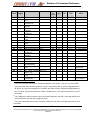
PAGE
I
II
III
IV
V
VI
VII
Viii
IX
X
XI
XII
XIII
XIV
XV
1
2
3
4
5
6
7
8
9
10
11
12
13
14
15
16
17
18
19
20
21
22
23
24
25
26
27
28
29
30
31
32
REVISION
B
B
B
B
B
B
B
B
B
B
B
B
B
B
B
B
B
B
B
B
B
B
B
B
B
B
B
B
B
B
B
B
B
B
B
B
B
B
B
B
B
B
B
B
B
B
B
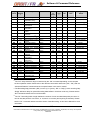
PAGE
33
34
35
36
37
38
39
40
41
42
43
44
45
46
47
48
49
50
51
52
53
54
55
56
57
58
59
60
61
62
63
64
65
66
67
68
69
70
71
72
73
74
75
76
77
78
79
REVISION
B
B
B
B
B
B
B
B
B
B
B
B
B
B
B
B
B
B
B
B
B
B
B
B
B
B
B
B
B
B
B
B
B
B
B
B
B
B
B
B
B
B
B
B
B
B
B
Doc. No. MAL-4164-4MC-PM.doc
PAGE
80
81
82
83
84
85
86
87
88
89
90
91
92
93
94
95
96
97
98
99
100
101
102
103
104
105
106
107
108
109
110
111
112
113
114
115
116
117
118
119
120
121
122
123
124
125
126
REVISION
B
B
B
B
B
B
B
B
B
B
B
B
B
B
B
B
B
B
B
B
B
B
B
B
B
B
B
B
B
B
B
B
B
B
B
B
B
B
B
B
B
B
B
B
B
B
B
- II -
PAGE
127
128
129
130
131
132
133
134
135
136
137
138
139
140
141
142
143
144
145
146
147
148
149
150
151
152
153
154
155
156
157
158
159
160
161
162
163
164
165
166
167
168
169
170
171
172
173
REVISION
B
B
B
B
B
B
B
B
B
B
B
B
B
B
B
B
B
B
B
B
B
B
B
B
B
B
B
B
B
B
B
B
B
B
B
B
B
B
B
B
B
B
B
B
B
B
B
PAGE
174
175
176
177
178
179
180
181
182
183
184
185
186
188
189
190
191
192
193
194
195
196
197
198
199
200
201
202
203
204
205
206
207
208
209
210
211
212
213
214
215
216
217
218
219
220
221
REVISION
B
B
B
B
B
B
B
B
B
B
B
B
B
B
B
B
B
B
B
B
B
B
B
B
B
B
B
B
B
B
B
B
B
B
B
B
B
B
B
B
B
B
B
B
B
B
B
Rev. B
Information contained herein is the sole property of ORBIT/FR and is not for publication, duplication, and it may not
be passed to any other party without written authorization from
ORBIT/FR.
FORWARD
PAGE
222
223
224
225
226
227
228
229
230
231
232
233
234
235
236
237
238
239
240
241
242
243
244
245
246
247
248
249
250
251
252
253
254
255
256
257
258
259
260
261
262
263
264
265
266
267
268
269
270
271
272
273
274
275
276
277
278
279
280
281
282
283
284
REVISION
B
B
B
B
B
B
B
B
B
B
B
B
B
B
B
B
B
B
B
B
B
B
B
B
B
B
B
B
B
B
B
B
B
B
B
B
B
B
B
B
B
B
B
B
B
B
B
B
B
B
B
B
B
B
B
B
B
B
B
B
B
B
B
PAGE
285
286
287
288
289
290
291
292
293
294
295
296
297
298
299
300
301
302
303
304
305
306
307
308
309
310
311
312
313
314
315
316
317
318
319
320
321
322
323
324
325
326
327
328
329
330
331
332
333
334
335
336
337
338
339
340
341
342
343
344
345
346
347
REVISION
B
B
B
B
B
B
B
B
B
B
B
B
B
B
B
B
B
B
B
B
B
B
B
B
B
B
B
B
B
B
B
B
B
B
B
B
B
B
B
B
B
B
B
B
B
B
B
B
B
B
B
B
B
B
B
B
B
B
B
B
B
B
B
Doc. No. MAL-4164-4MC-PM.doc
PAGE
348
349
350
351
352
353
354
355
356
357
358
359
360
361
362
363
364
365
366
367
368
369
370
371
372
373
374
375
376
377
378
379
380
381
382
383
384
385
386
387
388
389
390
391
392
393
394
395
396
397
398
399
400
401
402
403
404
405
406
407
408
409
410
REVISION
B
B
B
B
B
B
B
B
B
B
B
B
B
B
B
B
B
B
B
B
B
B
B
B
B
B
B
B
B
B
B
B
B
B
B
B
B
B
B
B
B
B
B
B
B
B
B
B
B
B
B
B
B
B
B
B
B
B
B
B
B
B
B
- III -
PAGE
411
412
413
414
415
416
417
418
419
REVISION
B
B
B
B
B
B
B
B
B
PAGE
REVISION
Rev. B
Information contained herein is the sole property of ORBIT/FR and is not for publication, duplication, and it may not
be passed to any other party without written authorization from
ORBIT/FR.
FORWARD
SAFETY SUMMARY
These are general safety precautions that are related to any specific
procedure. These are recommended precautions that personnel
must understand and apply.
WARNING
Use care when using metal tools that circuits are not shorted.
Some circuits have high current capacity which, when shorted, will
flash and may cause burns and/or eye injury.
Remove all jewelry and exposed objects from body and clothing
before performing maintenance, adjustments, and/or
troubleshooting. Before working inside equipment, remove all
power; unless power is required to be on to perform procedures.
Do NOT replace parts or modules with power ON.
Servicing this equipment requires working with the equipment while
the equipment while AC power is applied. Extreme caution must be
exercised during these procedures.
Doc. No. MAL-4164-4MC-PM.doc
- IV -
Rev. B
Information contained herein is the sole property of ORBIT/FR and is not for publication, duplication, and it may not
be passed to any other party without written authorization from
ORBIT/FR.
FORWARD
WARNING
Use care verifying that the electrical current that is written on the
sticker attached to the AL-4164-4MC Controller matches the
electrical current used in your country.
If any changes are required please follow the instructions detailed
hereafter:
1. Open the top cover of the AL-4164-4MC.
2. Release dip switch from its socket the AL-4164-4MC. (Please
refer to Figure A).
Terminal Connector
Figure A.
Doc. No. MAL-4164-4MC-PM.doc
-V-
Rev. B
Information contained herein is the sole property of ORBIT/FR and is not for publication, duplication, and it may not
be passed to any other party without written authorization from
ORBIT/FR.
FORWARD
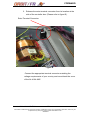
3. Release the extra terminal connector from its location at the
side of the controller box. (Please refer to figure B).
Extra Terminal Connector
Figure B.
Connect the appropriate terminal connector matching the
voltage requirements of your country and mount back the cover
of the AL-4164-4MC
Doc. No. MAL-4164-4MC-PM.doc
- VI -
Rev. B
Information contained herein is the sole property of ORBIT/FR and is not for publication, duplication, and it may not
be passed to any other party without written authorization from
ORBIT/FR.
FORWARD
RESUSCITATION
Personnel working with or near hazardous chemical or voltages should be
familiar with modern methods of resuscitation.
USE SAFETY - APPROVED EQUIPMENT
When cleaners are being applied, approved explosion-proof lights, blowers,
and other equipment shall be used. Ensure that firefighting equipment is
readily available and in working order. Keep cleaners in special polyethylene
bottles or in safety cans and in minimum quantities. Discard soiled cloths into
safety cans.
Doc. No. MAL-4164-4MC-PM.doc
- VII -
Rev. B
Information contained herein is the sole property of ORBIT/FR and is not for publication, duplication, and it may not
be passed to any other party without written authorization from
ORBIT/FR.
FORWARD
Table of Contents
1.
AL-4164-4MC SOFTWARE & COMMAND REFERENCE ................................................... 1
1.1
INTRODUCTION................................................................................................................. 1
1.2
GLOSSARY.......................................................................................................................... 2
1.3
COMMANDS SYNTAX AND PROTOCOLS ................................................................................ 11
1.3.1
General ........................................................................................................................... 11
1.3.2
Supported Communication Channel Protocols...............................................................11
1.3.3
Controller Communication Language Definitions ......................................................... 13
1.4
MOTION MODES ................................................................................................................... 25
1.4.1
Point To Point – PTP (MM=0, SM=0)........................................................................... 26
1.4.2
Repetitive Point To Point – Rep PTP (MM=0, SM=1)................................................... 31
1.4.3
Jogging – JOG (MM=1, SM=0) ..................................................................................... 33
1.4.4
Monitoring a Motion....................................................................................................... 34
1.4.5
Stopping a Motion...........................................................................................................34
1.4.6
Gearing Motion Modes................................................................................................... 36
1.4.7
ECAM Motions ............................................................................................................... 41
1.4.8
Search Index ................................................................................................................... 47
1.4.9
Joystick Motion Modes ................................................................................................... 48
1.4.10
Position Step Motion (MM=8 , SM=0 or SM=1) ...................................................... 49
1.4.11
Profile Smoothing in the AL-4164-4MC Controllers Family..................................... 51
1.5
THE CONTROL FILTER .......................................................................................................... 56
1.5.1
General ........................................................................................................................... 56
1.5.2
Linear PID and PIV Filter Equations.............................................................................61
1.5.3
Standard PID Filter Mode..............................................................................................61
1.5.4
PIV Filter Mode.............................................................................................................. 62
1.5.5
High (2nd) Order Filters.................................................................................................. 64
1.5.6
Output Command and D2A Gain.................................................................................... 66
1.5.7
PWM Command Format................................................................................................. 67
1.5.8
Encoder Gain.................................................................................................................. 68
1.5.9
Non-Linear Elements ...................................................................................................... 68
1.5.10
Filter Gain Scheduling............................................................................................... 70
1.5.11
Acceleration and Velocity Feed Forward .................................................................. 71
1.5.12
Open Loop Operation ................................................................................................ 72
1.5.13
AL-4164-4MC Open Loop Operation - SIN commutation motors ............................ 73
1.5.14
Real Time Servo Loop Protections............................................................................. 74
1.5.15
Summary of all Control Filter Related Parameters ................................................... 75
Doc. No. MAL-4164-4MC-PM.doc
- VIII -
Rev. B
Information contained herein is the sole property of ORBIT/FR and is not for publication, duplication, and it may not
be passed to any other party without written authorization from
ORBIT/FR.
FORWARD
1.6
FAULTS PROTECTIONS AND LIMITS ...................................................................................... 76
1.6.1
Driver Faults and Abort Input ........................................................................................ 77
1.6.2
Software Generated Faults ............................................................................................. 79
1.6.3
Motor Stuck Protection................................................................................................... 81
1.7
SOFTWARE PROTECTIONS – (NON FAULT CONDITIONS) ...................................................... 82
1.7.1
1.8
ADVANCED FEATURES ......................................................................................................... 84
1.8.1
Data Recording............................................................................................................... 84
1.8.2
Operating Data Recording in the AL-4164-4MC Controller’s Family .......................... 85
1.8.3
Data Recording Keywords..............................................................................................86
1.8.4
Data Recording Support on the AL-4164-4MC Shell ..................................................... 92
1.8.5
Position Compare Events ............................................................................................... 93
1.8.6
Mode 0: Fixed GAP (Incremental), Distance < 16 Bit...................................................94
1.8.7
Mode 1: Fixed GAP (incremental) , Distance > 16 Bit ..................................................96
1.8.8
Mode 2: 32 Bit Arbitrary Tables..................................................................................... 97
1.8.9
Mode 3: 32 Bit Arbitrary Tables with FPAG RAM Support........................................... 98
1.8.10
Compare Function Parameters, Activation and Error Codes.................................... 98
1.8.11
Configuring Digital Outputs for the Compare Function.......................................... 104
1.8.12
Position Compare Events Examples ........................................................................ 108
1.8.13
Position Capture Events .......................................................................................... 111
1.8.14
Capture Modes......................................................................................................... 112
1.8.15
Operating the Position Capture and Relevant Keywords ........................................ 112
1.8.16
Position Capture Events Examples .......................................................................... 116
1.8.17
Analog Input Interfaces............................................................................................ 119
1.8.18
Support for DC Brushless Motors - Sin ................................................................... 122
1.8.19
Dynamic Error Mapping Correction .......................................................................140
1.9
2.
Special Handling of Software Limits .............................................................................. 83
KEYWORDS REFERENCE ..................................................................................................... 141
1.9.1
Keywords Attribute Reference ...................................................................................... 141
1.9.2
Command Keywords List.............................................................................................. 143
1.9.3
Parameters Keywords List............................................................................................ 145
1.9.4
Keywords List – Functional Groups ............................................................................. 150
1.9.5
Keywords List – Alphabetical List ................................................................................ 157
SPECIAL FEATURES API ..................................................................................................... 172
2.1
VELOCITY FEEDBACK ........................................................................................................ 172
2.1.1
Tacho Velocity Feedback.............................................................................................. 172
2.1.2
Dual Encoder Velocity Feedback ................................................................................. 173
2.1.3
Configuration (CG) Command bits .............................................................................. 173
2.2
HOMING ............................................................................................................................. 174
Doc. No. MAL-4164-4MC-PM.doc
- IX -
Rev. B
Information contained herein is the sole property of ORBIT/FR and is not for publication, duplication, and it may not
be passed to any other party without written authorization from
ORBIT/FR.
FORWARD
2.2.1
Description ................................................................................................................... 174
2.2.2
Homing Related Parameters......................................................................................... 176
2.2.3
Homing Status Values................................................................................................... 177
2.3
EN-DAT ABSOLUTE ENCODER SUPPORT .......................................................................... 179
2.4
GENERAL PURPOSE L I/O’S ................................................................................................ 180
2.4.1
AL-4164-4MC Description ........................................................................................... 180
2.4.2
Input Port (IP) .............................................................................................................. 181
2.4.3
Output Ports .................................................................................................................182
2.5
2.5.1
Input Port (IP) .............................................................................................................. 183
2.5.2
Output Ports .................................................................................................................184
2.6
CONTINUOUS JOGGING MOTIONS AND COMPARE IN THIS MODE ....................................... 185
2.7
GENERAL PARAMETERS AND COMMANDS ......................................................................... 187
2.7.1
3.
BIT results bits.............................................................................................................. 189
COMMANDS SYNTAX AND PROTOCOLS ....................................................................... 190
3.1
GENERAL ........................................................................................................................... 190
3.2
SOFTWARE COMMUNICATION INTERFACES......................................................... 190
3.3
SUPPORTED COMMUNICATION PROTOCOLS ....................................................................... 191
3.3.1
3.4
Simultaneous Communication Channels Operation Support .......................................193
LANGUAGE DEFINITION ..................................................................................................... 193
3.4.1
General ......................................................................................................................... 193
3.4.2
Language Notations...................................................................................................... 194
3.5
3.5.1
3.6
AXES IDENTIFIERS AND GROUPS ........................................................................................ 198
AL-4164-4MC Family Controllers Axes Identifiers...................................................... 198
RS232 COMMUNICATION ............................................................................................ 202
3.6.1
General ......................................................................................................................... 202
3.6.2
Hardware Interfaces..................................................................................................... 202
3.6.3
Language Syntax...........................................................................................................202
3.6.4
AL-4164-4MC To Host ................................................................................................. 206
3.7
4.
AL4162-2MC I/P MAP....................................................................................................... 183
CAN COMMUNICATION............................................................................................... 209
3.7.1
Syntax - Host to AL-4164-4MC Controller...................................................................210
3.7.2
Syntax AL-4164-4MC Controller to Host ..................................................................... 222
3.7.3
CAN - Download Buffer Mode...................................................................................... 225
3.7.4
CAN - Enhanced Download Buffer Mode (EDB) .........................................................228
MACRO LANGUAGE ............................................................................................................. 235
4.1
INTRODUCTION............................................................................................................. 235
4.2
THE AL-4164-4MC MACRO ENGINE ............................................................................ 237
Doc. No. MAL-4164-4MC-PM.doc
-X-
Rev. B
Information contained herein is the sole property of ORBIT/FR and is not for publication, duplication, and it may not
be passed to any other party without written authorization from
ORBIT/FR.
FORWARD
4.2.1
General AL-4164-4MC Macro Program Structure ......................................................237
4.2.2
External Communication vs. Macro Execution Priority............................................... 238
4.2.3
Macro Handling Keywords...........................................................................................238
4.2.4
Low-Level Expressions Handling and the Numbers Stack ........................................... 240
4.2.5
Variables And Indirect Addressing...............................................................................245
4.2.6
Labels And Subroutines Names .................................................................................... 249
4.2.7
Macro Flow Control ..................................................................................................... 252
4.2.8
Wait and Internal State Inquiry Functions ................................................................... 256
4.3
TIMER FUNCTIONS ....................................................................................................... 261
4.3.1
Automatic Routines –Not Supported, Future Option .................................................... 262
4.3.2
Accessing Remote Units Via CAN Communication ......................................................264
4.3.3
External Communication Link Interfaces (RS-232)......................................................266
4.4
NOTES REGARDING THE LOW-LEVEL AL-4164-4MC MACRO PROGRAM........ 269
4.4.1
Macro and Motions.......................................................................................................269
4.4.2
Macro Syntax Check And Run-Time-Error................................................................... 270
4.4.3
Macro Size And Number Of Labels .............................................................................. 270
4.4.4
Macro Download Format ............................................................................................. 271
4.5
THE INTEGRATED DEVELOPMENT ENVIRONMENT............................................. 272
4.5.1
General ......................................................................................................................... 272
4.5.2
Writing and Editing AL-4164-4MC Macro Files.......................................................... 273
4.5.3
AL-4164-4MC SCShell Support for Downloading Macro Files to the AL-4164-4MC
Hardware .................................................................................................................................... 274
4.5.4
4.6
THE IDE PRE-COMPILER SUPPORT ........................................................................... 289
4.6.1
General ......................................................................................................................... 289
4.6.2
Non Executable Code - Comments Blanks Etc. ............................................................ 291
4.6.3
Directive Commands .................................................................................................... 292
4.6.4
Advanced Expressions Parsing..................................................................................... 296
4.7
4.7.1
4.8
5.
SrcEdit Macro Debugger Environment Features ......................................................... 278
APPLICATION EXAMPLES........................................................................................... 309
Example #1 ................................................................................................................... 309
AL-4164-4MC SCRIPT KEYWORDS COMMANDS REFERENCE APPENDIX ........ 320
4.8.1
Task Based Reference ................................................................................................... 320
4.8.2
Task Description........................................................................................................... 320
4.8.3
Task Based Command list............................................................................................. 320
4.8.4
Macro Programming Keywords Reference ..................................................................327
4.8.5
ZR - Remote Report Value (CAN Networking) .............................................................380
4.8.6
Pre-Compiler Directives and Keywords....................................................................... 382
MACRO SOURCE CODE EDITOR ...................................................................................... 386
Doc. No. MAL-4164-4MC-PM.doc
- XI -
Rev. B
Information contained herein is the sole property of ORBIT/FR and is not for publication, duplication, and it may not
be passed to any other party without written authorization from
ORBIT/FR.
FORWARD
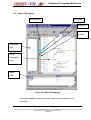
5.1
GENERAL ........................................................................................................................... 386
5.2
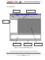
MAIN SCREEN .................................................................................................................... 387
5.3
WORKSPACE ...................................................................................................................... 389
5.4
MACRO EDITING ................................................................................................................ 391
5.5
MACRO DOWNLOADING ..................................................................................................... 393
5.6
MACRO DEBUGGING .......................................................................................................... 394
5.7
MENUS ............................................................................................................................... 397
5.7.1
File Menu......................................................................................................................397
5.7.2
New ............................................................................................................................... 397
5.7.3
Open ............................................................................................................................. 397
5.7.4
Close ............................................................................................................................. 397
5.7.5
Workspace .................................................................................................................... 397
5.7.6
Save............................................................................................................................... 399
5.7.7
Save As.......................................................................................................................... 399
5.7.8
Save All......................................................................................................................... 399
5.7.9
Print.............................................................................................................................. 400
5.7.10
Print Preview ........................................................................................................... 400
5.7.11
Print Setup ............................................................................................................... 400
5.7.12
File Locations .......................................................................................................... 400
5.7.13
Recent Files.............................................................................................................. 401
5.7.14
Recent Workspace.................................................................................................... 401
5.7.15
Exit........................................................................................................................... 401
5.7.16
Edit Menu................................................................................................................. 402
5.7.17
Options Menu...........................................................................................................405
5.7.18
View Menu ............................................................................................................... 408
5.7.19
Macro Menu............................................................................................................. 410
5.7.20
Communication Menu.............................................................................................. 415
5.7.21
Toolbars ................................................................................................................... 417
5.7.22
Source Code Editor Keyboard Shortcuts ................................................................. 419
Doc. No. MAL-4164-4MC-PM.doc
- XII -
Rev. B
Information contained herein is the sole property of ORBIT/FR and is not for publication, duplication, and it may not
be passed to any other party without written authorization from
ORBIT/FR.
FORWARD
List of Figures
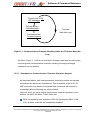
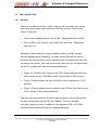
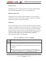
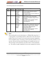
Figure 1-1: Communication Channels Handling within the Firmware Main Idle Loop ............ 12
Figure 1-2: Typical motion profile with full smoothing. ............................................................ 53
Figure 1-3: Typical motion with no profile smoothing. ............................................................. 54
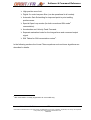
Figure 1-4: Position Over Velocity Loop (PIV) Control Scheme Structure ............................. 58
Figure 1-5: Position Loop (PID) Control Scheme Structure .................................................... 59
Figure 1-6: Position PID and Velocity PI Filters. ..................................................................... 60
Figure 1-7: Analog Input Scaling Block Diagram................................................................... 119
Figure 3-1. Communication Channels Handling within the Firmware Main Idle Loop ......... 192
Figure 4-1: Macros and Source Buffer ................................................................................. 237
Figure 4-2. Typical Servo Controller CAN network configuration......................................... 265
Figure 4-3. AL-4164-4MC Shell application main window.................................................... 272
Figure 4-4. Editing an AL-4164-4MC macro file with the Editor, SrcEdit.exe....................... 273
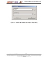
Figure 4-5. AL-4164-4MC SCShell file Locations Setup dialog ........................................... 277
Figure 4-6. SrcEdit Debugger Window ................................................................................. 281
Figure 4-7. SrcEdit -Debugger Window Toolbar .................................................................. 283
Figure 4-8. Reporting Descriptive directive information ....................................................... 295
Figure 4-9. Mathematical parsing example ......................................................................... 300
Figure 5-1. Source Code Editor Main Screen ....................................................................... 387
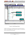
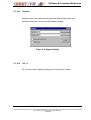
Figure 5-2: Workspace Area.................................................................................................. 389
Figure 5-3: Macro Editing ...................................................................................................... 391
Figure 5-4: Macro Debugging................................................................................................ 394
Figure 5-5: Debugging Area Example ................................................................................... 396
Figure 5-6: Source Code Edit File Location Dialog ............................................................... 400
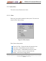
Figure 5-7: Find Dialog .......................................................................................................... 403
Figure 5-8: Replace Dialog.................................................................................................... 404
Figure 5-9: Editor Options ..................................................................................................... 405
Figure 5-10: Colors Dialog..................................................................................................... 406
Figure 5-11: Edit Toolbar....................................................................................................... 417
Figure 5-12: Debug Toolbar .................................................................................................. 418
Doc. No. MAL-4164-4MC-PM.doc
- XIII -
Rev. B
Information contained herein is the sole property of ORBIT/FR and is not for publication, duplication, and it may not
be passed to any other party without written authorization from
ORBIT/FR.
FORWARD
List of Tables
Table 1-1: Control Filter Parameters. ...................................................................................... 75
Table 1-2: “PG” Array in AL-4164-4MC- Compare Function Parameters Description ............ 99
Table 1-3: Error Codes Generated by the "PQ" Compare Function .................................... 103
Table 1-4: AL-4164-4MCKeywords Attributes and Restrictions............................................ 142
Table 1-5: AL-4164-4MC Commands Keywords List ........................................................... 144
Table 1-6: AL-4164-4MC Parameters Keywords List........................................................... 146
Table 1-7: Motion and Profiler Related Keywords................................................................. 151
Table 1-8: Control Filter and Real time Servo Loop Related Keywords................................ 152
Table 1-9: Data Recording Related Keywords ...................................................................... 153
Table 1-10: Special Encoder Interface Related Keywords.................................................... 153
Table 1-11: I/O Functions Related Keywords........................................................................ 154
Table 1-12: Communication and Configuration Keywords .................................................... 155
Table 1-13: Protection Keywords .......................................................................................... 155
Table 1-14: General Purpose Related Keywords.................................................................. 156
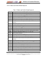
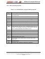
Table 3-1: AL-4164-4MC Axis Identifiers .............................................................................. 198
Table 3-2: AL-4164-4MC Keyword Axes Attributes.............................................................. 199
Table 3-3: AL-4164-4MC Real Axes Identifiers..................................................................... 203
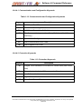
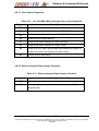
Table 3-4: Virtual Axes Identifier .......................................................................................... 204
Table 3-5: Virtual Axes Identifier .......................................................................................... 204
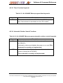
Table 3-6: CAN Bus Pre-Fix Byte Format ............................................................................ 210
Table 3-7: Pre-Fix Axes identifiers ....................................................................................... 211
Table 3-8: Normal Clause CAN Bus Message Format.......................................................... 213
Table 3-9: Non-Normal Array Clause CAN Bus Message Format ....................................... 216
Table 3-10: EDB Buffers For The AL-4164-4MC .................................................................. 229
Table 4-1: AL-4164-4MC Macro Program handling keywords .............................................. 239
Table 4-2: AL-4164-4MC Macro program operators. ............................................................ 243
Table 4-3: AL-4164 Macro Program Flow Control Keywords............................................... 252
Table 4-4: AL-4164-4MC Macro Program wait and state Inquiry Keywords ........................ 257
Table 4-5: AL-4164-4MC Macro Program, Internal wait Conditions .................................... 258
Table 4-6: AL-4164-4MC Macro program timer keywords ................................................... 261
Table 4-7:AL-4164-4MC Macro program timer keywords ..................................................... 262
Table 4-8: ScrEdit Debugger window Toolbar and Menu functions ..................................... 283
Table 4-9: AL-4164-4MC Macro program handling keywords ............................................. 321
Table 4-10: AL-4164-4MC Macro program operators ........................................................... 322
Table 4-11. AL-4164-4MC Macro program flow control keywords...................................... 323
Doc. No. MAL-4164-4MC-PM.doc
- XIV -
Rev. B
Information contained herein is the sole property of ORBIT/FR and is not for publication, duplication, and it may not
be passed to any other party without written authorization from
ORBIT/FR.
FORWARD
Table 4-12: Wait and Internal State Inquiry Functions ......................................................... 323
Table 4-13: AL-4164-4MC Macro program timer keywords. ................................................. 324
Table 4-14: AL-4164-4MC Macro program automatic routines control keywords................. 324
Table 4-15: AL-4164-4MC Macro program remote CAN access commands....................... 325
Table 4-16: AL-4164-4MC Macro program, external communication interfaces ................. 326
Table 4-17: Pre-compiler directive commands and Keywords............................................. 326
Table 5-1: Source Code Editor Keyboard Shortcuts ............................................................ 419
Doc. No. MAL-4164-4MC-PM.doc
- XV -
Rev. B
Information contained herein is the sole property of ORBIT/FR and is not for publication, duplication, and it may not
be passed to any other party without written authorization from
ORBIT/FR.
Software & Command Reference
1.
AL-4164-4MC SOFTWARE & COMMAND REFERENCE
1.1
INTRODUCTION
The AL-4164-4MC is a new advanced, state of the art, multi axes servo
controller, enhancing the ORBIT/FR products family line.
This chapter covers the product general Software User’s Manual and describes
the Command Reference of the new AL-4164-4MC servo controllers.
This manual is based on previous versions that supported the AL-4164-4MC
controller.
The main purpose of this User’s Manual is to provide full information over the
supported software features of the product, as well as to give a user technical
reference for each keyword supported by the communication protocol.
Doc. No. MAL-4164-4MC-PM.doc
-1-
Rev. B
Information contained herein is the sole property of ORBIT/FR and is not for publication, duplication, and it may not be passed
to any other party without written authorization from
ORBIT/FR.
Software & Command Reference
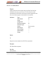
1.2
GLOSSARY
The following definitions are used within this manual. Please note that these
definitions are provided only for the scope of the AL-4164-4MC products and
this manual.
Abort Input
A dedicated digital input typically connected to the
machine’s emergency button. When the AL-41644MC detects an active state at this input it
immediately disables all motor drivers.
Clause
A single, complete, independent, communication
statement that can be interpreted and evaluated.
Each clause consists of keywords and operators and
is terminated by a terminator (to identify end of
clause).
Clause -
A communication statement sent by a host and
Assignment
instructs the Controller to assign a value to a
specified parameter. A typical assignment clause
consists of:
Keyword
Clause - Command
“=”
value
terminator
A communication statement sent by a host and
instructs the Controller to perform a specified
command (process). A command clause consists of:
Keyword
Doc. No. MAL-4164-4MC-PM.doc
-2-
terminator
Rev. B
Information contained herein is the sole property of ORBIT/FR and is not for publication, duplication, and it may not be passed
to any other party without written authorization from
ORBIT/FR.
Software & Command Reference
Clause - Report
A communication statement sent by a host and
instructs the AL-4164-4MC to report the value of a
specified parameter. A typical report clause consists
of:
Keyword
terminator
Clause -
A character that identifies end of communication
Terminator
clause. It can be <CR> or “;” in the communication
from a host to a Controller, or “>” in the opposite
direction (all for the RS232 line).
Command
The Commands Interpreter is an internal software
Interpreter
module of the AL-4164-4MC firmware, responsible
for interpreting Clauses sent to the controller. The
Command Interpreter handles all commands passed
to the AL-4164-4MC.
Communication
The low-level hardware and software definition of a
Protocol
communication channel. In RS232, for example, it
includes the baud-rate, handshake options, parity,
etc.
Communication
The rules that define the correct sequence of
Syntax, Language
characters that may create a valid communication
Syntax
clause.
Digital Control
An algorithm that is periodically executed (16,483
Filter
times per second in the AL-4164-4MC). The
algorithm compares the desired motor position and
its actual position to calculate a command to the
Doc. No. MAL-4164-4MC-PM.doc
-3-
Rev. B
Information contained herein is the sole property of ORBIT/FR and is not for publication, duplication, and it may not be passed
to any other party without written authorization from
ORBIT/FR.
Software & Command Reference
motor to minimize the difference between these
values.
The new Controller Digital Control Filter algorithm
supports both standard position based PID, as well
as Position Over Velocity loop structure. The new
AL-4164-4MC products support additional advanced
features. Please see the relevant chapter in this
User’s manual under “Control Filter Algorithms”.
Echo
In RS-232 mode, the AL-4164-4MC controller’s
automatically echoes (send a copy back) each
character that it receives during normal
communication. The returned character can be used
by the host to verify proper communication.
In the binary CAN bus communication protocol,
ECHO is not supported. Only OK/ERR prompt is
used.
Error Codes
In case that the AL-4164-4MC encounters an error
when interpreting a received clause, it ignores this
clause and responds with “?” before the returned
terminator (“>”). The AL-4164-4MC also stores a
code for the interpretation error at a parameter
named “EC” – which can be later reported to analyze
the error source.
A separate parameter “QC” holds the error codes of
any program running in the controller (Scripts or
Macro).
Doc. No. MAL-4164-4MC-PM.doc
-4-
Rev. B
Information contained herein is the sole property of ORBIT/FR and is not for publication, duplication, and it may not be passed
to any other party without written authorization from
ORBIT/FR.
Software & Command Reference
Fault Input
A dedicated digital input whose source is typically the
motor’s driver. It is used to inform the AL-4164-4MC
about a driver’s malfunction – for which the AL-41644MC needs to inhibit the driver and to abort all
motion activities.
Firmware Version
The AL-4164-4MC executes an internal firmware
Downloading
(BIOS) to perform all its tasks. From time to time new
firmware versions are released (corrections of
problems, new features, etc.). New firmware version
will be supplied by ORBIT/FR (or be available from
our web site). The AL-4164-4MC, together with the
SCShell, enables the downloading of a new version
via the RS232 (ONLY !) line
FLASH Memory
The AL-4164-4MC includes a 16M[bits] FLASH
memory for its firmware, parameters and user
program. The FLASH memory enables the
downloading of a new firmware version.
Host
A computer, terminal, PLC or any other device which
may send communication clauses to the AL-41644MC, via one of its communication links.
Identifiers – Axes
The AL-4164-4MC Commands Syntax always
requires an axis identifier before the keyword itself. If
a Keyword attribute is non-axis related, any axis
identifier is legal, and will have the same result. The
Command Interpreter ignores the axis identifiers of
non-axis-related keywords.
Doc. No. MAL-4164-4MC-PM.doc
-5-
Rev. B
Information contained herein is the sole property of ORBIT/FR and is not for publication, duplication, and it may not be passed
to any other party without written authorization from
ORBIT/FR.
Software & Command Reference
Identifiers – Group
The AL-4164-4MC Commands Syntax support the
Axes
concept of Axes Group identifier definition. An Axes
Group allows the user to define an arbitrary sub-set
of controller axes to be acted upon 1. Like in normal
axes identifiers, the Command Interpreter ignores the
Group Identifier of non-axis-related keywords.
The AL-4164-4MC supports up to 4 axes Groups
identifiers: A, B, C, D. The A and B Groups always
have the default of “All” and “Both” (X and Y)
assignments after power up.
Inhibit Output
A dedicated digital output of the AL-4164-4MC (one
for each axis) that is used to enable/disable an
external motor’s driver. The inhibit output reflects the
state of the MO parameter.
Incremental
A standard position sensor used as a position
Encoder
feedback in conjunction with motors and servo
systems. A special AL-4164-4MC hardware circuit
uses the encoder’s signals to continuously sense the
motor/load position (and speed) and to accordingly
control the motor motion.
Keyword
A token, consisting of 2 characters, which identifies a
unique AL-4164-4MC command or parameter.
1
Keyword
Each Keyword of the AL-4164-4MC has one or more
Attributes
attributes. The Keyword attribute tells the command
The SC-AT-2M does not support configurable Axis groups.
Doc. No. MAL-4164-4MC-PM.doc
-6-
Rev. B
Information contained herein is the sole property of ORBIT/FR and is not for publication, duplication, and it may not be passed
to any other party without written authorization from
ORBIT/FR.
Software & Command Reference
Interpreter how to be treated. For example, a
Keyword can be an axis related Keyword (related to
an axis) or Global Keyword.
Limit – Hardware
Most motion systems have mechanical end-of-travel
RLS, FLS
stops (especially with linear load motion). In order to
prevent the load from hitting these stops, an
electronic device/switch is located before each stop
(Reversed and Forward) to detect this situation.
These switches are connected to the AL-4164-4MC
RLS and FLS digital inputs (Reverse Limit Switch
and Forward Limit Switch). When the AL-4164-4MC
detects an active state at one of these inputs it stops
any motion toward the related direction.
Limits – Software
Similarly to the hardware limits (RLS and FLS
HL, LL
above), the Controller supports software limitation for
motion range. HL (High Limit) and LL (Low Limit)
defines a position range in which the AL-4164-4MC
operates normally. Whenever the motor’s position
exceeds this range, the AL-4164-4MC stops any
motion to the related direction.
Motion - Modes
Motion Mode defines the method in which the AL4164-4MC calculates the desired position command
as a function of time. The AL-4164-4MC supports
various motion modes. The basic modes are listed
below:
Point To Point (PTP).
Jogging.
ECAM.
Doc. No. MAL-4164-4MC-PM.doc
-7-
Rev. B
Information contained herein is the sole property of ORBIT/FR and is not for publication, duplication, and it may not be passed
to any other party without written authorization from
ORBIT/FR.
Software & Command Reference
Gearing.
Step.
Repetitive Step and PTP.
Motion - Profiling
Motion Profiling is the actual algorithm that calculates
new reference points to the servo loop according to
the selected Motion Mode.
Motion - On-The-
A characteristic of the AL-4164-4MC family that
Fly Changing
enables the modification of most of its parameters
even when they are active. For example, the PID
parameters can be modified while the motor is in
servo loop (motor is on).
A unique characteristic of the AL-4164-4MC is that
most (except profile smoothing) of its motion
parameters (such as: speed, acceleration,
deceleration, distance, etc.) can be modified on the
fly, under almost any conditions.
Position Capture
The Capture Position feature supported by the new
Events
AL-4164-4MC family products is the ability of the
encoder interface hardware to capture (latch) the
exact encoder location when a pre-defined Input or
encoder Index is detected.
The Capture hardware can latch encoder position
when counting at ANY encoder speed.
The Capture mechanism can be programmed to
latch encoder positions based on a user defined
digital input, or encoder index pulse.
Position Compare
Doc. No. MAL-4164-4MC-PM.doc
The Compare Position feature supported by the new
-8-
Rev. B
Information contained herein is the sole property of ORBIT/FR and is not for publication, duplication, and it may not be passed
to any other party without written authorization from
ORBIT/FR.
Software & Command Reference
Events
AL-4164-4MC product is the ability of the encoder
interface hardware to compare the actual encoder
hardware counter value to a pre-defined user register
value, and to generate a H/W pulse when there is a
condition match.
The basic compare mechanism can work at ANY
encoder speed. Compare mechanism can be
operated as a fixed GAP auto increment condition, or
variable GAP tables. See specific chapter later on in
this User’s Manual for further information.
Scripts or Macro
The AL-4164-4MC controller supports up to 10
Programming
simultaneous internal programs.
(Also referred to as “Scripts” or “Macro” programs).
Internal programs are used for tasks like Homing an
axis, or other user defined low level servo tasks.
The new AL-4164-4MC family controllers are
provided with an advanced SDI (“Software
Development Environment”), including very powerful
debugger and editor utilities, making Scripts
programming and debugging an easy task.
Sinusoidal
Electronic Sinusoidal Commutation is refereed to the
Electronic
ability of the controller to electronically and
Commutation
continuously control DC brushless motors phases
(Currently
commutation.
Supported in AL-
In brushless type motors, there are 2 main
4164-4MCOnly)
techniques for phase commutation. The traditional
“Trapezoidal” commutation, usually done within the
analog motor driver, and “Sinusoidal” commutation.
Doc. No. MAL-4164-4MC-PM.doc
-9-
Rev. B
Information contained herein is the sole property of ORBIT/FR and is not for publication, duplication, and it may not be passed
to any other party without written authorization from
ORBIT/FR.
Software & Command Reference
In Sinusoidal commutation the motor phase currents
are changed continuously as a function of the motor
magnetic angle.
In Electronic Sinusoidal Commutation the controller
generates the 2 phase current commands (to be
used by a special motor driver) as a function of the
encoder feedback reading.
Virtual Axes 2
The AL-4164-4MC support 2 Virtual axes, U and V.
The virtual axes are used for special features like
multiple axes synchronized motions, Master Slave,
etc.
Windows Shell
ORBIT/FR provides an enhanced Windows 9x (or
Program,
NT/2000/XP) application program (named SCShell)
SCShell
for easy and fast interface with the AL-4164-4MC
family controllers. Using the SCShell, starting-up or
verifying a new idea/concept is just few mouse clicks
away.
2
Currently not supported in the SC-AT-2M controller.
Doc. No. MAL-4164-4MC-PM.doc
- 10 -
Rev. B
Information contained herein is the sole property of ORBIT/FR and is not for publication, duplication, and it may not be passed
to any other party without written authorization from
ORBIT/FR.
Software & Command Reference
1.3
Commands Syntax and Protocols
1.3.1 General
This chapter mainly focuses on the AL-4164-4MC communication syntax,
including response to commands clauses and errors. The various
communication channel protocols are briefly presented for reference only.
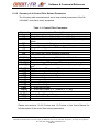
1.3.2 Supported Communication Channel Protocols
The AL-4164-4MC currently supports two basic communication Channel
protocols :
ASCII based RS-232
Binary CAN bus.
Using separate hardware interface layers, the RS-232 and CAN bus
communication links (and their protocols) are completely independent from
one another, and can be used simultaneously (excluding few special cases
as described in section 1.3.2.1 below).
Doc. No. MAL-4164-4MC-PM.doc
- 11 -
Rev. B
Information contained herein is the sole property of ORBIT/FR and is not for publication, duplication, and it may not be passed
to any other party without written authorization from
ORBIT/FR.
Software & Command Reference
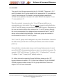
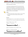
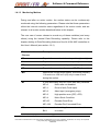
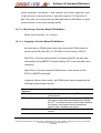
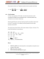
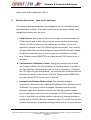
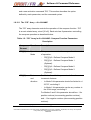
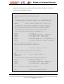
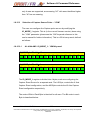
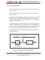
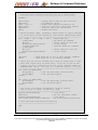
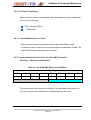
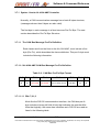
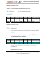
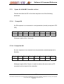
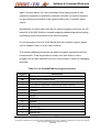
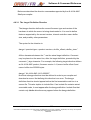
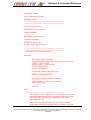
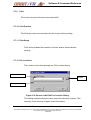
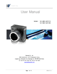
Process ASCII RS232 Messages
Process Binary
CAN Messages
Firmware
Main Idle Loop
Process Internal
Scripts Programs
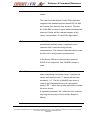
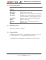
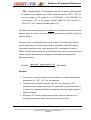
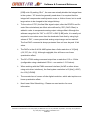
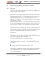
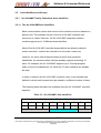
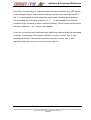
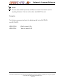
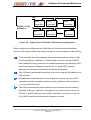
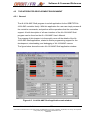
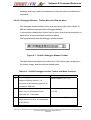
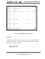
Figure 1-1: Communication Channels Handling within the Firmware Main Idle
Loop
As shown Figure 1-1, the servo controllers’ firmware main loop is continuously
monitoring both communication channels; handling incoming messages
separate from one another.
1.3.2.1 Simultaneous Communication Channels Operation Support
As discussed above, both communications channel protocols can operate
simultaneously without any interference. This is possible in the AL-41644MC architecture as almost all keywords and commands are executed
immediately without blocking any other process.
However, there are some special cases where a special operation in one
channel can block the other. These cases are:
When downloading new firmware in RS-232 (Supported ONLY in RS232), all other channels are immediately disabled.
Doc. No. MAL-4164-4MC-PM.doc
- 12 -
Rev. B
Information contained herein is the sole property of ORBIT/FR and is not for publication, duplication, and it may not be passed
to any other party without written authorization from
ORBIT/FR.
Software & Command Reference
When downloading a new user program in one of the channels, the
other channel is blocked for the same operation. Other communication
with the second channel is fully functional.
When uploading large arrays in one channel, other channels will be
blocked until the upload operation is completed.
1.3.3
Controller Communication Language Definitions
1.3.3.1 General
In the following sub-sections, the controller basic communication language
is defined.
It should be noted that the same “Language Syntax Rules” applies,
regardless of the command source, which can be one of: RS-232
Communication, CAN bus Communication, Possible other future supported
communication links, and the Internal script program engine.
When a new command is received from either one of the channels
described above, its source is recorded for later reference, and the
command itself is passed to an internal software module “The Command
Interpreter”, which checks its syntax, and if a valid command is detected,
executes the command.
1.3.3.2 Language Notations
The communication keywords are divided into two groups of Keywords:
Parameters Keywords.
Command Keywords.
Doc. No. MAL-4164-4MC-PM.doc
- 13 -
Rev. B
Information contained herein is the sole property of ORBIT/FR and is not for publication, duplication, and it may not be passed
to any other party without written authorization from
ORBIT/FR.
Software & Command Reference
The execution time of a parameter keyword is minimal and usually negligible
(few micro-seconds at most). The execution time of a command may be
longer (for example: save parameters, or upload list data). Below please find
the definitions of each Keyword type group.
1.3.3.2.1 Parameters Keywords
Parameters can always report their value (generally reflecting the value of
an internal software or hardware register) and in most cases can be
assigned with a value. There are some read only parameters that cannot
be assigned with a new value. For example, the “AI” (Analog Input value) is
a read only parameter.
There are some parameters that when assigned with a new value, can also
modify the values of other parameters. For example, when modifying the
“PS” (Current Encoder Position Value) of an axis, the “DP” (The current
position command reference or Desired Position) is also modified to the
same value to avoid positioning errors.
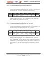
1.3.3.2.2 Command Keywords
Command Keywords always initiates a process (start a motion, save
parameters, begin internal script program execution, etc.). Commands
does not report a specific register values, and in general, does not assign
any specific register values, though they can internally modify values of
more then one register. For example, the “BR” (Begin Recording)
command, will modify the value of the “RR” (Recording Status) register.
Doc. No. MAL-4164-4MC-PM.doc
- 14 -
Rev. B
Information contained herein is the sole property of ORBIT/FR and is not for publication, duplication, and it may not be passed
to any other party without written authorization from
ORBIT/FR.
Software & Command Reference
The “LD” (Load from Flash) command will modify values of almost ALL
registers!
Commands can receive a parameter (actually an argument) which effects
the command process. For example, the command to execute a program
(“QE”) can receive a label string argument, indicating the name of the
subroutine to execute (e.g. “XQE,#HOME”). Command’s parameter can
be a string (see above), or a number. The command’s parameter is
separated from the command itself using a comma “,” character.
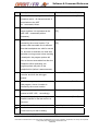
1.3.3.2.3 Keywords Attributes and Restrictions
Each Keyword has attributes defining it, and restrictions that must be
satisfied in order to accept the command clause. The Command
Interpreter module checks the restrictions before actually executing the
command or making a parameter assignment. For parameters, the
restrictions relate only for assignment, since reporting is always valid.
(For a complete list of ALL attributes and restrictions please refer to
section 1.9.1 Keywords Attribute Reference).
Restrictions, for both parameters and commands, may be one or more of
the following list (the restriction attribute value is given for reference, see
section 1.9.1 Keywords Attribute Reference for more information):
None: No restriction is applicable.
Motor Should be ON (0x00000001): The requested command or
parameter assignment needs an enabled motor. For example, the
“BG” (begin motion) command must have its related motor enabled
in order to be executed successfully.
Motor Should be OFF (0x00000002): The requested command or
parameter assignment needs a disabled motor. For example, the
“CG” (axis configuration) parameter can be assigned with a new
Doc. No. MAL-4164-4MC-PM.doc
- 15 -
Rev. B
Information contained herein is the sole property of ORBIT/FR and is not for publication, duplication, and it may not be passed
to any other party without written authorization from
ORBIT/FR.
Software & Command Reference
value ONLY if its related motor is disabled. The assignment can not
be executed if the motor is enabled.
Motion Should be ON (0x00000004): The requested command or
parameter assignment can be executed only if a motion is currently
being executed.
Motion Should be OFF (0x00000008): The requested command or
parameter assignment can be executed only if there is no current
motion. For example, the Motion Mode (“MM”) parameter can not be
changed during motion.
Parameter is Read Only (0x00000010): A Read-Only parameter
can only be inquired for its value. The user can not assign values for
Read-Only parameters. For example, “DP” (the current reference
Desired Position value) is a read only parameter, and can not be
directly assigned a new value by the user.
Keyword Source MUST be an internal program (0x00100000):
The keyword can only be used from an internal script program. For
example, the “RT” (return from subroutine) command can only be
called from with in a program subroutine.
Keyword Source MUST be external Communication
(0x00200000): The keyword can only be used from an external
communication link. For example, the “QD” (download a new
program) command can only be called from an external
communication link.
Keyword Source MUST be RS-232 Communication
(0x00400000): The keyword can only be called from an RS-232 link.
For example downloading new Firmware is supported ONLY in RS232 mode.
Keyword Source MUST have all internal programs halted
(0x10000000): The keyword can only be executed when all internal
user programs are halted. For example, the “LD” command (Load
from flash), can be called only in that case.
Doc. No. MAL-4164-4MC-PM.doc
- 16 -
Rev. B
Information contained herein is the sole property of ORBIT/FR and is not for publication, duplication, and it may not be passed
to any other party without written authorization from
ORBIT/FR.
Software & Command Reference
Parameter values always have a minimum and maximum value for
assignment clauses. Most parameters are saved to FLASH. Few are
initialized to default non-active values on power-on, reset, or load-fromFLASH events.
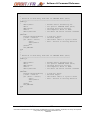
1.3.3.2.4 Axes Identifiers and Groups
The AL-4164-4MC family controllers support Group Definitions for Axes
Identifiers. The AL-4164-4MC controller language syntax requires an axis
identifier before any Keyword. When a specific axis identifier is given, the
command interpreter will interpret the clause and will act upon the
specific axis only.
In order to let the user perform an action on more then one axis
simultaneously, for example, reporting position of all axes at once, the
notation of Group Axes Identifiers is supported by the AL-4164-4MC
command interpreter.
Doc. No. MAL-4164-4MC-PM.doc
- 17 -
Rev. B
Information contained herein is the sole property of ORBIT/FR and is not for publication, duplication, and it may not be passed
to any other party without written authorization from
ORBIT/FR.
Software & Command Reference
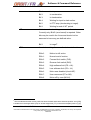
AL-4164-4MC
There are 4 Axes Groups supported by the AL-4164-4MC. These are: A, B, C
and D. By default, the “A” group stands for ALL axes and the “B” group defines
X and Y axes sub-group. For example, issuing the following assignment
“APS=0” set the position of all axes to “0”, while “BPS=0” set only the “X” and
“Y” axes position to “0”.
When the controller is powered-up, the “A” and “B” group definitions are
automatically set to their default. The user cannot change the default definition
of the “A” and “B” groups, nor save them to the FLASH memory. After power up,
the user can however define other values to the “A” and “B” groups, although
this is not recommended. As a design rule we recommend to use “A” and “B”
always as their default initial definitions. If other sub-groups are needed it is
recommended to use the “C” and “D” groups.
The “C” and “D” groups can be assigned to any value. The definition is saved to
the flash memory with all other controller parameters, and can be used after
power up.
Group definition is simply made using a new bit array filed parameter for each
group. Each BIT in the parameter defines an axis to be related to the group. For
example, “1023” (all 10 bits are “1”) defines “ALL”. “1” defines the “X” axis only.
“3” defines “X” and “Y” axes (the ”B” default) and so on.
For further information regarding Groups Definitions please see the “GP”
keyword reference in section 1.9.3.1 in this User’s Manual. The AL-4164-4MC
SCShell program provides an easy GUI for groups definitions. Please see
chapter 1.8.10 for more information.
Doc. No. MAL-4164-4MC-PM.doc
- 18 -
Rev. B
Information contained herein is the sole property of ORBIT/FR and is not for publication, duplication, and it may not be passed
to any other party without written authorization from
ORBIT/FR.
Software & Command Reference
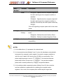
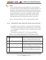
NOTE
In the current firmware version, when working in CAN bus communication, a
multiple axes report command for a group with more then 2 axes will report
ONLY the first two axes values. This limitation is currently implied due to the
8 bytes basic CAN message format. This limitation may be removed in
future firmware versions.
1.3.3.3
Controller Language Syntax
In the following section the general Language Syntax of the AL-4164-4MC
family servo controller’s software is presented. Please note that while the
discussion below mostly refers to the RS-232 ASCII protocol, the CAN bus
protocol is logically similar.
1.3.3.3.1 Host to SC
Each keyword consists of two upper case letters. Some of the parameters
are defined as arrays. These parameters are always referred to with their
two letters keyword and with an index number within a square brackets,
e.g. AR[2].
Each command clause is terminated with a terminator character, which
may be one of <CR> or “;”.
Each command clause is preceded with an axis identification letter, to
identify the axis to which the command clause is addressed. It might be
one of the following characters:
Doc. No. MAL-4164-4MC-PM.doc
- 19 -
Rev. B
Information contained herein is the sole property of ORBIT/FR and is not for publication, duplication, and it may not be passed
to any other party without written authorization from
ORBIT/FR.
Software & Command Reference
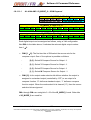
AL-4164-4MC Axis Prefixes
X’, ‘Y’, ‘Z’, ‘W’, ‘E’, ‘F’, ‘G’, ‘H’ and ‘U’, ‘V’ – for axes 1 through 8, and for
the 2 additional Virtual axes (total of 10 axes interface).
‘B’ for Both – After power up, ‘B’ always refers to the ‘X’ and ‘Y’ axes. This
is done for backward compatibility.
A’ for All – After power up, ‘A’ always refers to all axes !.
‘C’ and ‘D’: two additional user defined groups.
All groups (‘A’, ‘B’, ‘C’, ‘D’) can be configured to define any subset of axes
using a special new Group assign parameter.
Some of the command clauses are not axis related (e.g.: SV for saving
parameters to the FLASH or the AR for the global general-purpose array). In
these cases the axis identification letter is ignored, although it still must be
included.
The Command Interpreter handles a command clause only after the
termination character has been received. Next command clause characters
are received (buffered) but are not handled until the current command
handling is completed.
Each command clause includes only a single keyword. The keyword may be
a command or a parameter.
In case of a command keyword, the command clause will include the
command keyword (preceded with the axis identification letter), with optional
parameters (string or numbers), separated with a comma (‘,’).
In case of a parameter keyword, the command clause may be a report or a
set parameter clause.
A report parameter value command clause includes only the parameter
keyword (with index in square brackets for arrays).
Doc. No. MAL-4164-4MC-PM.doc
- 20 -
Rev. B
Information contained herein is the sole property of ORBIT/FR and is not for publication, duplication, and it may not be passed
to any other party without written authorization from
ORBIT/FR.
Software & Command Reference
A set parameter value command clause includes the parameter keyword
(with index in square brackets for arrays), “=” and the value. The parameter
value is a decimal, long integer and in text format (printable characters).
NOTES
Blanks, tabs and new-line characters are received, echoed but ignored.
Back-spaces are handled.
Examples:
XSP <CR>
YSP ;
XAR[5]<CR>
Report parameter clauses
YSP= 10000;
BAC = 1000000 <CR>
BAR[3]=345 ;
XBG <CR>
AST ;
YQE,#HOME_X
Set parameter clauses
Commands
Command to execute a subroutine named
“HOME_X” using the ‘Y’ script engine.
1.3.3.3.2 Controller To Host
Each character (including blanks, tabs, new-line and terminators) is
echoed as is, unless otherwise is selected by the user (EO command:
Echo On/Off).
In case of a report parameter clause, the reported value is sent back to the
host (decimal, long integer, text format in RS-232, and binary format in
CAN bus).
After handling each command clause, a prompt is sent back to the host
computer. The prompt is “>” in case of a successful command clause
Doc. No. MAL-4164-4MC-PM.doc
- 21 -
Rev. B
Information contained herein is the sole property of ORBIT/FR and is not for publication, duplication, and it may not be passed
to any other party without written authorization from
ORBIT/FR.
Software & Command Reference
execution or “?>” in case of any error in the execution of the command
clause (command was not executed).
In the later case, a dedicated parameter (EC: Error Code) will hold the
code of the last communication error. In cases where the last error was
generated in a user script program, another dedicated parameter holding
the last program error code is updated. (QC: Program Error Code). For a
complete description of all currently supported error codes, please refer to
chapter 01.8.10 later on in this User’s Manual.
NOTES
An empty command clause is a legal “do nothing” or “Ping” command.
The prompt is sent only after the clause execution have been
completed.
Examples:
The italics strings are the AL-4164-4MC responses to the Host computer.
The blanks are only for the clarity of the example and the send/get timing.
Setting “SP” (Speed of X axis) to 10,000:
X S P =
X S P
1 0 0 0 0 ;
= 1 0 0 0 0 ;
Echo (only if EO=1)
>
Response (always sent)
Setting “AC” (Acceleration of X and Y by default) to 10,000:
B A C = 1 0 0 0 0 0 0 CR
B A C = 1 0 0 0 0 0 0 CR
Echo (only if EO=1)
Doc. No. MAL-4164-4MC-PM.doc
>
Response (always sent)
- 22 -
Rev. B
Information contained herein is the sole property of ORBIT/FR and is not for publication, duplication, and it may not be passed
to any other party without written authorization from
ORBIT/FR.
Software & Command Reference
Reporting the value of the Z axis SP :
Z S P CR
Z S P CR
10000
Echo (only if EO=1)
>
Response (always sent)
Reporting the value of the SP (for X and Y by default):
B S P ;
B S P ;
10000 , 20000 >
Echo (only if EO=1)
Response (always sent)
Reporting the value of the SP (Grouping axes, is supported in the AL4164-4MC only - for all axes, assuming A is configured to All axes):
A S P CR
A S P CR 100, 200, 300, 400, 500, 600, 700, 800, 900, 1000 >
Echo (only if EO=1)
Response (always sent)
Executing a Begin Motion Command for X and Y by default:
B B G CR
B B G CR
Echo (only if EO=1)
>
Response (always sent)
Trying to assign out of range value to YAC (error prompt is sent, and EC is
updated accordingly):
Y A C = - 1 0 0 0 CR
Y A C = - 1 0 0 0 CR
Echo (only if EO=1)
Doc. No. MAL-4164-4MC-PM.doc
? >
Response (always sent)
- 23 -
Rev. B
Information contained herein is the sole property of ORBIT/FR and is not for publication, duplication, and it may not be passed
to any other party without written authorization from
ORBIT/FR.
Software & Command Reference
Executing a Script function named “HOME_X” in Program #1 (X):
X Q E , # HOME_X CR
X Q E , # HOME_X CR
>
Echo (only if EO=1) Response (always sent)
Doc. No. MAL-4164-4MC-PM.doc
- 24 -
Rev. B
Information contained herein is the sole property of ORBIT/FR and is not for publication, duplication, and it may not be passed
to any other party without written authorization from
ORBIT/FR.
Software & Command Reference
1.4
Motion Modes
This chapter describes the various Motion Modes that are supported by the AL4164-4MC controller’s family. Motion Mode defines a type of motion. The exact
motion, for each Motion Mode, is defined by a set of related parameters, such
as speed (SP), acceleration (AC) and many other parameters.
While most of these parameters can be modified on-the-fly during an active
motion (practically affecting the motion profile), the Motion Mode itself can not
be modified during an active motion.
The Motion Mode for the AL-4164-4MC is defined by a combination of two
parameters: MM (Motion Mode) and SM (Special Motion Mode).
Most standard motion modes are defined by the value of MM, with SM=0.
Some special motion modes use both MM (to define the basic motion mode)
and SM (to define a special variation of it).
The following sections describe the details of each motion mode.
Please refer to the following notes:
The communication clauses given in the following sections for how to
start/stop and monitor each motion mode are just examples. A specific
application can use any desired value for the related parameters (such as
acceleration and speed).
The values of most parameters do not need to be sent again before each
motion. The controller will use the current value of each parameter when
a new motion is commanded.
Sometimes we use a semicolon ‘;’ mark between to commands. This is
simply to save space. The user can use the ‘;’ in all commands, or use
none.
Doc. No. MAL-4164-4MC-PM.doc
- 25 -
Rev. B
Information contained herein is the sole property of ORBIT/FR and is not for publication, duplication, and it may not be passed
to any other party without written authorization from
ORBIT/FR.
Software & Command Reference
1.4.1
Point To Point – PTP (MM=0, SM=0)
1.4.1.1 PTP Motion Description
In this mode the controller calculates a standard smoothed trapezoidal
profile from the current position to a user specified target position, using a
user specified acceleration and speed.
The profile is called trapezoidal since the velocity command has a
trapezoidal (or triangular for short distances) shape. The user can select to
smooth the profile in order “round” the sharp trapezoidal (or triangular)
corners. If smoothing is used, then the actual jerks are limited (no zero time
acceleration change). Without smoothing, the jerks are infinite (acceleration
is changed at “0” time).
The target position can be specified relatively to the current desired position,
using the RP (Relative Position) parameter. It can be also specified as an
absolute position, using the AP (Absolute Position) parameter.
It is important to note that a PTP motion is always executed toward the
value of the AP parameter. However, sending an RP=<value> clause is
internally interpreted as:
AP=DP+<value>,
Where DP is the current desired position (normally equal to the current
actual position).
As a result, the AP is indeed modified when a new value is assigned to RP,
and any following PTP motion toward AP will actually move to the desired
relative position.
Doc. No. MAL-4164-4MC-PM.doc
- 26 -
Rev. B
Information contained herein is the sole property of ORBIT/FR and is not for publication, duplication, and it may not be passed
to any other party without written authorization from
ORBIT/FR.
Software & Command Reference
The only disadvantage of this method is that, for repeated relative motions,
RP should be sent again before each motion.
The AL-4164-4MC controllers support separate AC (Acceleration) and DC
(Deceleration) values in all profile based motion types. Furthermore, a new
DL (Deceleration on Limit) parameter is supported in order to define a
special Deceleration values when Limits are hit (works both for software and
hardware limits).
1.4.1.2 Starting a PTP Motion
Communication
Description
Clauses
MO=1
Enabling the servo loop, motor on
MM=0;SM=0
Setting PTP motion mode
AC=500000
Assigning a value for the acceleration,
[counts/sec2]
DC=500000
Assigning a value for the deceleration,
[counts/sec2]
DL=1000000
Assigning a value for the Limit DC, [counts/sec2]
WW=0
Defines no smoothing.
SP=50000
Assigning a value for the speed, [counts/sec]
AP=100000
Assigning an absolute target position, [counts]
RP=30000
or, assigning a relative value for the target
position
BG
Doc. No. MAL-4164-4MC-PM.doc
Begin the motion
- 27 -
Rev. B
Information contained herein is the sole property of ORBIT/FR and is not for publication, duplication, and it may not be passed
to any other party without written authorization from
ORBIT/FR.
Software & Command Reference
1.4.1.3 Monitoring Motions
During and after an active motion, the motion status can be continuously
monitored using the following parameters. Please note that these parameters
reflect the internal controller status regardless of the motion mode, and are
relevant in all motion modes described below in this chapter.
The user can of course choose to record any of these variables (and many
others) using the internal Data Recording capability. Please refer to the
chapter dealing in Data Recording features of the AL-4164-4MC controllers in
this User’s Manual (see section 1.8.1).
Communication
Description
Clauses
PS
Reports the current actual motor position, [counts].
VL
Reports the current actual motor speed, [counts/sec].
DP
Reports the current desired position, [counts].
PE
Reports the current position error (DP-PS), [counts]
MO
Reports the current motor status. Should be normally
1 for motor on. Will be 0 (off) only in case of fault
during the motion.
MF
MS
A code describing why the motor was lastly disabled:
MF=0:
Motor was not disabled.
MF=1:
Driver’s fault (Fault input).
MF=2:
Abort input (emergency stop).
MF=3:
High position error (|PE| > ER).
MF=4:
Motor Stuck Condition.
MF=65:
Encoder Quad Error.
MF=129:
Encoder Dis-Connected Error.
A bitwise code describing the current motion status:
Bit 0:
Doc. No. MAL-4164-4MC-PM.doc
In motion.
- 28 -
Rev. B
Information contained herein is the sole property of ORBIT/FR and is not for publication, duplication, and it may not be passed
to any other party without written authorization from
ORBIT/FR.
Software & Command Reference
SR
Bit 1:
In stop.
Bit 2:
In acceleration.
Bit 3:
In deceleration.
Bit 4:
Waiting for input to start motion.
Bit 5:
In PTP stop (decelerating to target).
Bit 6:
Waiting for end of WT period.
A bitwise code describing some controller statuses.
Currently only Bit #5 (zero based) is reported. Other
bits may be used in the future and should not be
assumed to have any pre-defined value.
Bit 5:
EM
3
In target 3.
A code describing the cause for last end-of-motion:
EM=0:
Motion is still active.
EM=1:
Normal end-of-motion.
EM=2:
Forward limit switch (FLS).
EM=3:
Reverse limit switch (RLS).
EM=4:
High software limit (PS > HL).
EM=5:
Low software limit (PS < LL).
EM=6:
Motor was disabled (check MF).
EM=7:
User command (ST or AB).
EM=8:
Motor off by user (MO=0).
This bit indicates that the motion profile has been finished and that the absolute position error (|PE|)
is smaller than the target radius (TR) for at least target time (TT) consecutive samples (each 61 [μs]).
Doc. No. MAL-4164-4MC-PM.doc
- 29 -
Rev. B
Information contained herein is the sole property of ORBIT/FR and is not for publication, duplication, and it may not be passed
to any other party without written authorization from
ORBIT/FR.
Software & Command Reference
1.4.1.4 Stopping a Motion
A PTP motion is automatically finished when the desired position (the
motion profile, not the actual motor position) reaches the desired target
position. At this time the Motion Status (MS) is read as 0 and the controller
is ready for a new motion or a new motion mode.
The EM (End Motion) parameter is set to 1, indicating normal end-of-motion.
A PTP motion can be also stopped by the following communication clauses:
Communication
Description
Clauses
AB
Aborts the motion immediately (DP remains as
its last value).
ST
Stops the motion with deceleration to zero
speed.
MO=0
Disables the motor, effectively stopping any
motion.
Of course, any software or hardware fault, limitation, or protection will also
immediately abort or stop the motion (depending on the fault or limitation
type). The Last motion end reason can be monitored with the EM parameter.
Doc. No. MAL-4164-4MC-PM.doc
- 30 -
Rev. B
Information contained herein is the sole property of ORBIT/FR and is not for publication, duplication, and it may not be passed
to any other party without written authorization from
ORBIT/FR.
Software & Command Reference
1.4.1.5 On The Fly Parameters Change
The following parameters can be modified on-the-fly during an active PTP
motion:
Communication
Description
Clauses
SP
Starts an acceleration or deceleration toward the
new SP value.
AC,DC,DL
Defined new Accelerations and Decelerations for
the current motion.
RP
Changes motion (including direction) to move
toward the new AP (AP=DP+RP) value. RP can
be modified even during deceleration to the
previous target position and can be modified to
any value, independent of the current position.
AP
Changes motion (including direction) to move
toward the new AP. AP can be modified even
during deceleration to the previous target
position and can be modified to any value,
independent of the current position.
Note that AP (or RP) change during motion may cause the motor to change
its motion direction. This will happen if a new AP value is given to a point that
was already passed by the system.
1.4.2 Repetitive Point To Point – Rep PTP (MM=0, SM=1)
This mode is very similar to the standard PTP motion mode, as described
above.
Doc. No. MAL-4164-4MC-PM.doc
- 31 -
Rev. B
Information contained herein is the sole property of ORBIT/FR and is not for publication, duplication, and it may not be passed
to any other party without written authorization from
ORBIT/FR.
Software & Command Reference
However, repetitive motion mode supports motions back and forth between
two positions. Each motion is a standard PTP motion (uses SP, AC, DC etc.
as described above) but the controller automatically generates the sequence
of motions without the need to re-sending the BG command.
This mode is excellent for tuning the PID filter. The motor is commanded to
perform infinite motions back and forth, while the PID parameters are
modified on-the-fly to examine their effect on the motion performance
(optionally using the Data Recording feature).
Two additional keywords are used for the Repetitive PTP mode:
WT: Wait Time parameter, in samples
•
AL-4164-4MC each sample is 61
[μs].
WT Defines the wait time between consecutive motions. Upon BG, the
controller will generate a motion toward AP, waits WT samples and than
will generate a motion toward the original position, where it will wait
again WT samples, and so on forever.
KR: Kill Repetitive command.
Unlike a standard PTP motion, a Repetitive PTP motion does not
finished unless stopped by the user or any fault or limitation.
While AB and ST will act just as for a standard PTP motion, KR will stop
the repetitive sequence, completing the current PTP motion and only
then stopping.
Doc. No. MAL-4164-4MC-PM.doc
- 32 -
Rev. B
Information contained herein is the sole property of ORBIT/FR and is not for publication, duplication, and it may not be passed
to any other party without written authorization from
ORBIT/FR.
Software & Command Reference
A Repetitive PTP motion is started just as a standard PTP motion but with
SM=1, instead of SM=0. This means that the basic motion mode is still a
PTP motion (MM=0) but it has a special modification, identified by SM=1.
NOTES
Each motion segment within a repetitive motion is treated as a standard
PTP motion. The only difference is reflected in the SR parameter, bit 4
(In Repetitive PTP motion). In addition, when a motion segment is
finished and the motion is “paused” for WT samples, a dedicated bit in
MS will identify this status (bit 6).
Modifying AP on-the-fly will modify the target position of the current
segment but will not affect the 2nd target position (the “back” motion).
In the AL-4164-4MC controller’s the repetitive motion is also supported
under STEP mode (MM=8).
1.4.3
Jogging – JOG (MM=1, SM=0)
1.4.3.1 Description
In this mode the controller calculates a standard acceleration profile, using
the user specified acceleration (AC), toward the user specified speed (SP).
This speed is kept constant until the motion is stopped by a user
command.
In case of an ST (Stop) command, the controller calculates a deceleration
profile, using the user specified deceleration (DC).
The motion’s direction is set according to the sign of the SP (Speed)
parameter.
Doc. No. MAL-4164-4MC-PM.doc
- 33 -
Rev. B
Information contained herein is the sole property of ORBIT/FR and is not for publication, duplication, and it may not be passed
to any other party without written authorization from
ORBIT/FR.
Software & Command Reference
1.4.3.2 Starting a Jog Motion
Communication
Description
Clauses
MO=1
Enabling the servo loop, motor on
MM=1;SM=0
Setting Jogging motion mode
AC=500000
Assigning a value for the acceleration, [counts/sec2]
DC=200000
Assigning a value for the deceleration, [counts/sec2]
Used when stopped or when changing SP on the fly.
1.4.4
DL=1000000
Assigning a value for the Limit DC, [counts/sec2]
WW=0
Defines no smoothing.
SP=50000
Assigning a value for the speed, [counts/sec]
BG
Begin the motion
Monitoring a Motion
Please refer to section 1.4.1.3 above.
1.4.5
Stopping a Motion
A Jogging motion is, theoretically, an infinite motion. It stops only as a result
of a user command or due to some fault, limitation or protection.
A Jogging motion can be stopped by the following communication clauses:
Doc. No. MAL-4164-4MC-PM.doc
- 34 -
Rev. B
Information contained herein is the sole property of ORBIT/FR and is not for publication, duplication, and it may not be passed
to any other party without written authorization from
ORBIT/FR.
Software & Command Reference
Communication
Description
Clauses
AB
Aborts the motion immediately (DP remains as
its last value).
ST
Stops the motion with deceleration (using DC) to
zero speed.
MO=0
Disables the motor, effectively stopping any
motion.
Any software or hardware fault, limitation, or protection will also immediately
abort or stop the motion (depending on the fault or limitation type).
1.4.5.1 On The Fly Parameters Change
The following parameters can be modified on-the-fly during an active Jogging
motion:
Communication
Description
Clauses
SP
Starts an acceleration or deceleration toward the new
SP value. The New SP value can have a different
sign from the previous SP value.
AC, DC
Will affect any following motion toward a new SP
value.
Doc. No. MAL-4164-4MC-PM.doc
- 35 -
Rev. B
Information contained herein is the sole property of ORBIT/FR and is not for publication, duplication, and it may not be passed
to any other party without written authorization from
ORBIT/FR.
Software & Command Reference
1.4.6 Gearing Motion Modes
1.4.6.1 Position Based Gearing (MM=2)
1.4.6.1.1 Description
Gearing (or electronic gearing) motion is referring to a motion mode where an
axis follows another axis position with a pre-defined (fixed) ratio. AL-41644MC supports position gearing motion mode for X and Y axes only.
The position gearing is implemented based on a master DP follow method. In
this method, the follower axis is slaved to a (user selected) Master Axis
Desired Position (i.e. The Master’s DP, not its actual encoder position PS).
This method allows to perform very accurate multiple axes vector motions,
with one axis being used as a master, while other axes can be slaved to it’s
reference position (i.e. to the master’s theoretical profiler output).
NOTE
The master axis can be in Motor On or Off (i.e. MO=0) states. In the later
case, the Master’s DP=PS, so using a disabled axis as a master axis, will
provide true encoder position tracking.
The “FR” (Following Ratio) parameter is using a 32 bit, with fix point 8.24
format scaling resolution, to allow ratios of up to: × ±128, and : × ± 1/16,777,216.
The following dedicated parameters are used for Position Based Gearing
Motion:
-
“ME”: Master Encoder or Axis. This parameter defines which axis is the
Master axis for a given slave gear motion. On the AL-4164-4MC
Controllers, the “ME” parameter can be any valid physical axis (ME=0 for
X, ME=1 for Y, ME=2 for Z or ME=3 for W).
Doc. No. MAL-4164-4MC-PM.doc
- 36 -
Rev. B
Information contained herein is the sole property of ORBIT/FR and is not for publication, duplication, and it may not be passed
to any other party without written authorization from
ORBIT/FR.
Software & Command Reference
-
“FR”: Following Ratio. This parameter defines the slave’s following ratio
in relation to the Master’s axis (“ME”) reference position (“DP”). “FR” can
be any number in the range of: [-2,147,000,000 ÷ 2,147,000,000]. As
noted above, “FR” is an integer number scaled to 8.24 format. I.e.,
“FR=16,777,216” means a following ratio =1.0.
The slave axis reference position is relative to the master’s and slave’s initial
position when the slave axis was initially commanded to actually begin the
Gearing Motion.
Gearing motion is initialized like any other motion. This means that first the
motion parameters and mode should be set, and then a valid “BG” (Begin
Command) should be given. Upon issuing a “BG” command to an axis in
MM=2, first the master and slave initial positions are locked, and then the axis
enters a motion state where its reference is calculated according to the
following equation:
SlaveDP =
(MasterDP − MasterInitDP ) ⋅ FR + SlaveInitDP
16,777,216
Remarks:
For an axis in gearing motion mode (the slave), all other motion profiler
parameters (i.e. “SP”, “AC”, etc.) are ignored.
Users should avoid alter a master axis “DP” (by a issuing a “PS=”
command to the master axis) while it is connected to a slave axis that is
in motion, to avoid position Step Commands to the slave and possible a
high error faults.
Although “FR” can be change during motion, doing so will result in a
slave step command, which may cause a high error fault.
Doc. No. MAL-4164-4MC-PM.doc
- 37 -
Rev. B
Information contained herein is the sole property of ORBIT/FR and is not for publication, duplication, and it may not be passed
to any other party without written authorization from
ORBIT/FR.
Software & Command Reference
When an axis is commanded to begin a motion in MM=2, it immediately
enters the motion with the reference as defined above. No acceleration
profile is generated for cases where the master axis is already in motion.
Currently the AL-4164-4MC support position gearing motion mode for X
and Y axes only.
Like Jogging, Gearing Motion is also theoretically an infinite motion. It
stops only as a result of a user command or due to some fault,
limitations, or protections.
If a gearing motion is stopped (by a user “ST” command), or by other
faults like hardware or software Limits, the slave axis will start to
decelerate using the relevant Deceleration parameters: “DC” for normal
Stop commands (“ST”) and “DL” for Limit Stop conditions. In this case of
course, the axis is “loosing” the master’s tracking.
In Gear Motions “WW” (the smoothing parameter) must be “0”, since the
slave is directly following the master DP according to the equation
described above. “WW” different from “0” will not effect normal tracking,
but will cause a position step command when a Stop command is given.
Like in all other motions, an “AB” (abort motion) command will result in
immediate stop of motion without any deceleration profile.
Due to an implementation limitation, currently, only when X is following
Y, one (1) sample time delay (61 micro-sec in AL-4164-4MC) will be
present in the generated slave axis (X) reference profile, related to the
master profile (Y).
Doc. No. MAL-4164-4MC-PM.doc
- 38 -
Rev. B
Information contained herein is the sole property of ORBIT/FR and is not for publication, duplication, and it may not be passed
to any other party without written authorization from
ORBIT/FR.
Software & Command Reference
1.4.6.1.2 Starting a Position Based Gearing Motion
Communication
Description
Clauses
YMO=1
Enabling Y Axis servo loop, motor on
YMM=2;YSM=0
Set Y axis to Position Based Gear Mode
YME=0
Set Y Master Axis As X (Y will follow X)
YFR=1,048,576
Set Following Ratio to 1/16.
YBG
Start Y Motion (Following the X axis)
In this example, Y axis is command to follow the X axis reference position,
with ratio of 1/16. Note that usually, when an axis is intended to operate in
gear mode, the following axis is first being enabled and enters motion (BG),
and only afterwards the master axis is commanded to move. Starting a
gearing motion (BG with MM=2), where the master axis is already in motion
will result in velocity command step to the following axis.
1.4.6.1.3 Monitoring a Position Based Gearing Motion
Please refer to section 1.4.1.3 above.
1.4.6.1.4 Stopping a Position Based Gearing Motion
Gear motion is, theoretically, an infinite motion. It stops only as a result of a
user command or due to some fault, limitation, or protection.
A Gear motion can be stopped by the following communication clauses:
Doc. No. MAL-4164-4MC-PM.doc
- 39 -
Rev. B
Information contained herein is the sole property of ORBIT/FR and is not for publication, duplication, and it may not be passed
to any other party without written authorization from
ORBIT/FR.
Software & Command Reference
Communication
Description
Clauses
AB
Aborts the motion immediately (DP remains as
its last value).
ST
Stops the motion with deceleration (using DC) to
zero speed. Note that immediately after issuing
the “ST” command, the slave axis stops following
the master, and starts an autonomous stop
profile motion towards zero speed.
MO=0
Disables the motor, effectively stopping any
motion.
Any software or hardware fault, limitation, or protection will also immediately
abort or stop the motion (depending on the fault or limitation type).
Note: In gear motion, any fault condition acting on the master axis, will not
directly affect the following (slave) axis. This means that the following axis
remains linked to the master DP, regardless of the master’s motion status or
motor status. For example, if a master axis is disabled due to a high error
condition, its motor will be turned off, but the following axis will still be in
motion condition, and will keep following the disabled axis encoder.
1.4.6.1.5 On The Fly Parameters Change
An axis during gear motion is not affected by any of the normal profiler
motion parameters (e.g. SP, AC, etc.).
Although the following ratio (“FR”) can be modified during motion, it is not
recommended to do so, as this will result in a position and possibly also
velocity reference steps.
Doc. No. MAL-4164-4MC-PM.doc
- 40 -
Rev. B
Information contained herein is the sole property of ORBIT/FR and is not for publication, duplication, and it may not be passed
to any other party without written authorization from
ORBIT/FR.
Software & Command Reference
1.4.6.2 Velocity Based Gearing (MM=3)
Note: This mode is currently not fully implemented.
1.4.7 ECAM Motions
1.4.7.1 Position Based ECAM (MM=5, SM=0)
1.4.7.1.1 Description
Position based ECAM (Electronic CAM) is a unique motion mode that
allows one axis to follow a motion of another axis, based on a user defined
position location table. Currently (F/W Revision 2.05/D) the AL-4164-4MC
support position based ECAM motion mode for X and Y axes only.
The AL-4164-4MC support master reference position (“DP”) based ECAM
motion. In this mode, the position profile is taken from a set of values from
the “AR[]” array, actually performing a user defined contour. The time scale
is, instead of Time (as for Time based ECAM, see MM=4), the master “DP”
(Desired Position) value. The active master Axis can be selected from any
of the 4 available encoder inputs (axes X, Y, Z ,W in AL-4164-4MC) using
the “ME” (Master Encoder) command.
A new Array Parameter "EA" - ECAM Parameters Array (Size [4][8] in AL4164-4MC) was added to support the new ECAM motion mode:
-
“EA[1]”: (ES) ECAM Start Index. Points to the first point in AR[] to be
used for the ECAM.
-
“EA[2]”: (EW) ECAM Wrap Index. Points to the first point in AR[], to be
used for ECAM cycles following the first cycle.
Doc. No. MAL-4164-4MC-PM.doc
- 41 -
Rev. B
Information contained herein is the sole property of ORBIT/FR and is not for publication, duplication, and it may not be passed
to any other party without written authorization from
ORBIT/FR.
Software & Command Reference
-
“EA[3]”: (EE) ECAM End Index. Points to the last point in AR[] to be
used for the ECAM.
-
“EA[4]”: (EG) ECAN Gap. Defines the master distance (in [counts],
related to the master encoder) between two consecutive AR[] points.
-
“EA[5]”: (EN) ECAM Number Of Cycles. Defines the actual number of
ECAM cycles to be executed. If 0, ECAM is performed infinite number of
cycles, until stopped. If “EN > 0” the axis will perform “EN” complete
ECAM cycles.
-
“EA[6]”: (EI): ECAM Interpolation Mode. Defines the method used to
interpolate the position profile commands with an “EG” period (between
each two consecutive AR[] points). Currently only linear interpolation is
supported. “EI” should be always set to “0”.
-
“EA[7]”: (MI): Master Init Position. Defines the starting position of the
master. MI defines the starting position of the master. If MI is zero
(normal case) then the starting master position is set to the position of the
master at the time of the BG command. The ECAM table is than entered
according to relative master motions from this point. If MI is a non-zero
value, it is used to set the starting master position, instead of the above
method. This method is useful if the starting point of the ECAM was
captured using the position capturing option and the value captured
should be used to accurately define the starting position of the master. MI
is not saved to the FLASH and is initialized to zero after power-on or
reset. The user may set it to any value before starting an ECAM motion.
-
“EA[8]”: Is not used, and should not be initialized for future compatibility.
During the “BG” (Begin Motion) command, when MM=5, the ECAM
parameters (ES, EW, EE, etc.) are checked for their validity and a "?" is
returned in case of an error. In that case “EC” is set to 14
(EC_WRONG_MOTION_PARAM). The following conditions must be satisfied
for a proper initialization of ECAM motion:
Doc. No. MAL-4164-4MC-PM.doc
- 42 -
Rev. B
Information contained herein is the sole property of ORBIT/FR and is not for publication, duplication, and it may not be passed
to any other party without written authorization from
ORBIT/FR.
Software & Command Reference
- The ECAM Start Index (ES, EA[1]) must be >= 1.
- The ECAM Wrap Index (EW, EA[2]) must be >= ECAM Start Index (EA[1]).
- The ECAM End Index (EE, EA[3]) must be < AR_ARRAY_LENGTH
(10,000 for AL-4164-4MCor 16,000 for SC-AT-2M. In the SC-AT-2M the
array used is actually the DA array. Please refer to the “DA” keyword on
section 1.8.3.6).
- The ECAM Gap (EG, EA[4]) must be >= 1. Note that practically, this
number must be much larger then 1 (usually larger then 100).
- The ECAM Gap (EG, EA[4]) must be <= 32,767.
- The ECAM Number Of Cycles (EN, EA[5]) must be >= 0.
A New End Of Motion Reason was added. “EM”
EM_BAD_PROFILE_PARAM
= 9” is now used to indicate bad ECAM
parameters that are encountered during ECAM motion.
A new Array code for “EA” is implemented for the CAN bus interface. The
“EA” CAN Array Code is: 22.
The difference between each two consecutive AR[] points must be within the
range of +/-32767. No check is done and in case of values out of range,
unexpected motions may occur!
It is important to understand that ECAM mode uses the AR[] table data as a
relative trajectory reference, based on the initial position of the axis before
starting the ECAM motion. This means that usually, the first value in the
ECAM table is “0”, otherwise “jump” in the motion profile will be resulted.
After the number of requested ECAM cycles (EN) has been completed, the
motion is aborted and “DP” is set to the end-point value of this cycle (Initial
DP + AR[EE]).
Doc. No. MAL-4164-4MC-PM.doc
- 43 -
Rev. B
Information contained herein is the sole property of ORBIT/FR and is not for publication, duplication, and it may not be passed
to any other party without written authorization from
ORBIT/FR.
Software & Command Reference
Note that an ABORT command is used, not STOP. This is to ensure that the
final “DP” value will match the ECAM table value. It is the user’s responsibility
to ensure that the ECAM profile includes the deceleration part to avoid
sudden abort of motion when the number of cycles is completed.
As noted above, ECAM uses the general purpose AR[] array for Table Input
data.
In general, the Master Based ECAM works only for positive and monotonous
motion of the master axis. If the master moves in a negative direction, use the
relevant “CG” configuration bits to inverse its direction. Unexpected motions
can happen if the master does not perform positive motion. However, within
an ECAM cycle, the master can stop and even invert its motion direction
without any problems, as long as the master does not move below the Start
(ES) and above the End (EE) locations.
Another limitation is that the master axis should not perform more than a
complete ECAM cycle during the time between two consecutive samples (61
[us]). However, this limitation can be normally ignored since it practically
means bad ECAM parameters setup.
In ECAM Motions, “WW” (the smoothing parameter) must be “0”, since the
axis is using the table locations as a reference.
Doc. No. MAL-4164-4MC-PM.doc
- 44 -
Rev. B
Information contained herein is the sole property of ORBIT/FR and is not for publication, duplication, and it may not be passed
to any other party without written authorization from
ORBIT/FR.
Software & Command Reference
1.4.7.1.2 Starting a Position Based ECAM Motion
The following code sequence will initiate an ECAM motion of Y axis, with
X being the master. The ECAM motion is a triangular profile from 0 to
5000 and back to 0.
Communication
Clauses
YWW=0;YMO=1
YMM=5;YSM=0
YEA[1]=1;YEA[2]=1
YEA[3]=13
YEA[4]=10000
YEA[5]=1
YEA[7]=0
XAR[1]=0;XAR[2]=0
XAR[3]=1000
XAR[4]=2000
XAR[5]=3000
XAR[6]=4000
XAR[7]=5000
XAR[8]=5000
XAR[9]=4000
XAR[10]=3000
XAR[11]=2000
XAR[12]=1000
XAR[13]=0
YME=0
YBG
Description
Enable Y Axis servo loop, motor on, No
Smoothing
Set Y axis to Position Based ECAM Mode
Set ECAM Start and Wrap Indexes to 1 (i.e.
AR[1])
Set ECAM End Index to 13 (i.e. AR[13])
Set ECAM Gap to 10,000 counts.
Set ECAM Number of Cycles to “1”.
Set Normal Master Init Position. The Master
position at BG will be used as the Master Init
Position.
Initialize the ECAM Table (AR[1] to AR[13]).
Set Y Master Axis As X (Y will follow X)
Begin the motion for Y axis
In this example, the ECAM Gap is 10,000 counts (referring to the master’s, X
axis, position), while the distance between each two-table-point is 0 or 1,000
Doc. No. MAL-4164-4MC-PM.doc
- 45 -
Rev. B
Information contained herein is the sole property of ORBIT/FR and is not for publication, duplication, and it may not be passed
to any other party without written authorization from
ORBIT/FR.
Software & Command Reference
counts (referring to the slave’s, Y axis, position). As a result, when the X and
Y axes will move, the speed of the Y axis will be exactly 1/10 that of the X
axis. The users can of course set any table data such as SIN tables to create
circular motions, or any other arbitrary profile.
1.4.7.1.3 Monitoring a Position Based ECAM Motion
Please refer to section 1.4.1.3 above.
1.4.7.1.4 Stopping a Position Based ECAM Motion
As noted above, ECAM motion stops when the actual ECAM number of
cycles equals EN (when EN > 0). ECAM is an infinite motion if EN=0.
When EN > 0 and the actual number of cycles equals EN, the axis stop
immediately (using ABORT Command) setting “DP” to the last table value
(relatively).
When EN=0, in order to stop the ECAM motion, users should use the
STOP or ABORT commands.
In general, like any other motion, an ECAM motion can be stopped by the
following communication clauses:
Communication
Clauses
AB
ST
MO=0
Doc. No. MAL-4164-4MC-PM.doc
Description
Aborts the motion immediately (DP remains as
its last value).
Stops the motion with deceleration (using DC) to
zero speed. Note that immediately after issuing
the “ST” command, the slave axis stops following
the master, and starts an autonomous stop
profile motion towards zero speed.
Disables the motor, effectively stopping any
motion.
- 46 -
Rev. B
Information contained herein is the sole property of ORBIT/FR and is not for publication, duplication, and it may not be passed
to any other party without written authorization from
ORBIT/FR.
Software & Command Reference
Of course, any software or hardware fault, limitation, or protection will
also immediately abort or stop the motion (depending on the fault or
limitation type).
NOTE
Like in Gearing motions, in ECAM motion also, any fault condition acting
on the master axis, will not directly effect the following (slave) axis. This
means that the following axis remains linked to the master DP, regardless
of the master’s motion status or motor status. For example, if a master
axis is disabled due to a high error condition, its motor will be turned off,
but the following axis will still be in motion condition, and will keep
following the disabled axis encoder, even after it is stopped.
1.4.7.1.5 On The Fly Parameters Change
An axis during ECAM motion is not affected by any of the normal profiler
motion parameters (e.g. SP, AC, etc.).
Changing any of the ECAM motion parameters has no effect once motion
has been started.
1.4.8 Search Index
The AL-4164-4MC controllers do not have a special dedicated motion mode
for search index. This is done by an internal macro as part of homing macro
Doc. No. MAL-4164-4MC-PM.doc
- 47 -
Rev. B
Information contained herein is the sole property of ORBIT/FR and is not for publication, duplication, and it may not be passed
to any other party without written authorization from
ORBIT/FR.
Software & Command Reference
1.4.9 Joystick Motion Modes
1.4.9.1 Velocity Based Joystick Motion Mode
1.4.9.1.1 Description
This mode is very similar to the Jogging mode. However, instead of jogging
in the user specified SP value, the jogging speed is taken from the analog
input (assuming it is connected to a Joystick or any other source of analog
voltage).
The analog input parameter AI is used instead of SP. All other parameters
(AC, DC etc.) are used exactly as for Jogging mode.
Note: This mode is currently not fully implemented.
1.4.9.2
Position Based Joystick Motion Mode
1.4.9.2.1 Description
This mode is very similar to the standard PTP mode. However, instead of
using the user specified Absolute Position (AP) parameter as the target
position, this modes uses the Analog Input (AI) parameter as its target
position.
Since a standard PTP mode supports on-the-fly modification of the AP
parameter, this mode automatically supports the changes of the AI during
the motion, practically tracking them with the user specified acceleration
(AC) and speed (SP) parameters,
Doc. No. MAL-4164-4MC-PM.doc
- 48 -
Rev. B
Information contained herein is the sole property of ORBIT/FR and is not for publication, duplication, and it may not be passed
to any other party without written authorization from
ORBIT/FR.
Software & Command Reference
These parameters need to be high enough to enable good tracking on the
joystick motions (variations of the AI parameter) but low enough to avoid
“nervous” motions.
An important note is that when this mode is activated using the required
MM and SM values, the AP parameter is continuously and internally
assigned with the AI value.
Note: This mode is currently not fully implemented.
1.4.10
1.4.10.1
Position Step Motion (MM=8 , SM=0 or SM=1)
Description
In this mode the Desired Position (DP) is assigned with the Absolute
Position (AP) immediately after the Begin (BG) command. The profiler
does not generate any motion profile and the AC, DC and SP values are
ignored. The theoretical Motion time in this mode is “0” by definition (True
Step command).
This mode is useful for the measurement of the closed loop step response
and bandwidth. It is generally not used in practical applications since it
generates infinite acceleration and jerk. MM=8 can be combined with
SM=1 to generate repetitive step motions.
Note that you can also use the Relative Position (RP) parameter.
Assigning a value to RP will anyhow modify the value of AP properly.
Note that the value of the step should be smaller than ER to avoid High
Error fault. In addition, high step values can cause oscillations due to the
non-linearity’s (especially saturation), which are an inherent part of the
control loop.
Doc. No. MAL-4164-4MC-PM.doc
- 49 -
Rev. B
Information contained herein is the sole property of ORBIT/FR and is not for publication, duplication, and it may not be passed
to any other party without written authorization from
ORBIT/FR.
Software & Command Reference
1.4.10.2
Starting a Step Motion
Communication
Description
Clauses
MO=1
Enabling the servo loop, motor on
MM=8;SM=1
Setting Position Step motion mode (Repetitive
Mode)
AP=100
Assigning an absolute target position, [counts]
RP=30
or, assigning a relative value for the target
position
BG
Begin the motion
Note that the AL-4164-4MC controllers also support repetitive Step
Motions. Similarly, this can be done by setting SM=1 instead of SM=0 in
the above sequence. WT is used as the delay time between each two
consecutive motions.
1.4.10.3 Monitoring and Stopping a Step Motion
Please refer to section 1.4.1.3 above.
Note that the Step motion mode is very short (one sample time). As a
result, it is practically impossible to monitor the state of this motion.
In addition, a Step motion does not affect the EM parameter, which
remains with the same value it has before the BG command.
Since the Step motion is very short, it is not practical to stop it after a BG
command.
Doc. No. MAL-4164-4MC-PM.doc
- 50 -
Rev. B
Information contained herein is the sole property of ORBIT/FR and is not for publication, duplication, and it may not be passed
to any other party without written authorization from
ORBIT/FR.
Software & Command Reference
If a repetitive Step Motion is commanded, the user should use the KR (Kill
repetitive) command, much like a normal PTP Rep motion.
1.4.11 Profile Smoothing in the AL-4164-4MC Controllers Family
The AL-4164-4MC controllers Family support an advanced, symmetric Scurve like profile smoothing algorithm. The smoothing is controlled by the
WW parameter.
WW can be set to 0 to avoid any profile smoothing. In that case the
generated position velocity profile is pure trapezoidal (or triangular).
If WW is set to 12, the smoothing is set to its maximal value. In that case the
generated profile has full smoothing, and the velocity trajectory is not pure
trapezoidal.
The WW parameter is used by the controller as a power of 2 coefficients for
the smoothing time value. For example, WW=6 means that smoothing is
done over a period of time of 2^6 sample time - In the AL-4164-4MC this will
take approx. 4 msec.
Setting WW=12 to its Maximal smoothing value of 2^12, will result in a 0.25
sec. (AL-4164-4MC) acceleration smooth period.
The following figures shows two simple profiles generated in similar motion
parameters, with different smoothing values.
For both motions, the following general parameters are used:
AC=DC=1,000,000
SP=100,000
AP=100,000
Doc. No. MAL-4164-4MC-PM.doc
- 51 -
Rev. B
Information contained herein is the sole property of ORBIT/FR and is not for publication, duplication, and it may not be passed
to any other party without written authorization from
ORBIT/FR.
Software & Command Reference
In one case no smoothing is used (WW=0), and in the other full smoothing is
defined (WW=12).
Figure 1-2 below shows the motion profile with full smoothing implemented
in the profile. Note the smooth velocity profile (the upper window in red).
There are no “sharp” corners in the generated velocity profile.
Doc. No. MAL-4164-4MC-PM.doc
- 52 -
Rev. B
Information contained herein is the sole property of ORBIT/FR and is not for publication, duplication, and it may not be passed
to any other party without written authorization from
ORBIT/FR.
Software & Command Reference
The resulted acceleration profile (not shown in the graph) is of course
continuous and dose not have any sudden “step” changes.
Figure 1-2: Typical motion profile with full smoothing.
Figure 1-3 below shows the same motion profile with no smoothing at all
implemented in the profile. Note the sharp “trapezoidal” velocity profile (the
upper window in red).
Doc. No. MAL-4164-4MC-PM.doc
- 53 -
Rev. B
Information contained herein is the sole property of ORBIT/FR and is not for publication, duplication, and it may not be passed
to any other party without written authorization from
ORBIT/FR.
Software & Command Reference
The resulted acceleration profile (not shown in the graph) is not continuous,
and includes 0 time acceleration changes (jerks).
Note also the resulted actual motor velocity seen slightly overshooting in this
case in both constant speed and zero speed settlings (the blue actual motor
speed graph overshooting the red desired speed graph in the upper
window).
Figure 1-3: Typical motion with no profile smoothing.
Doc. No. MAL-4164-4MC-PM.doc
- 54 -
Rev. B
Information contained herein is the sole property of ORBIT/FR and is not for publication, duplication, and it may not be passed
to any other party without written authorization from
ORBIT/FR.
Software & Command Reference
Note that profile-smoothing implementation does not imply any numerical
limitations, and does not include any “minimal motion time” limit, which might
be implied by the use of the smoothing itself.
The user should be aware that theoretically, a smoothed profile takes longer
time to complete then a similar trapezoidal profile with no smoothing.
The actual time difference between the non-smoothed theoretical
trapezoidal profile to the smoothed one depends on all motion profile
parameters (SP, AC, DC and the motion distance of course).
In any case, the maximal time difference does not exceed the overall
smoothed period (2^WW sample times).
Doc. No. MAL-4164-4MC-PM.doc
- 55 -
Rev. B
Information contained herein is the sole property of ORBIT/FR and is not for publication, duplication, and it may not be passed
to any other party without written authorization from
ORBIT/FR.
Software & Command Reference
1.5
The Control Filter
1.5.1 General
The AL-4164-4MC controller’s family, supports, as a standard, two control
filter structures to allow users maximum flexibility in servo control loops
tuning. These are:
• Full Position feedback based control loop - Designated below as PID.
• Dual, Position over Velocity, loop control filter structure - Designated
below as PIV.
Although in the presence of a single feedback device (usually a single
encoder based position feedback) it is easy to show that the two control
schemes are identical (there exist a transformation converting from one filter
constants to the other), there are few benefits (mainly for the tuning process)
for the PIV configuration that will be discussed below.
• Figure 1-4: Position Over Velocity Loop (PIV) Control Scheme Structure
below shows the AL-4164-4MC control loop structure in PID scheme.
• Figure 1-5 below shows the AL-4164-4MC control loop structure in PIV
scheme.
• Figure 1-6 below shows both the position loop PID filter and Velocity loop
(in PIV Mode) PI filter implementations.
The User can select between the two control schemes, using a special bit in
the axis configuration word (CG[3] zero based). The AL-4164-4MC
controller’s family includes, in addition to the standard (PID or PIV) filter
structures some additional features as described below:
Doc. No. MAL-4164-4MC-PM.doc
- 56 -
Rev. B
Information contained herein is the sole property of ORBIT/FR and is not for publication, duplication, and it may not be passed
to any other party without written authorization from
ORBIT/FR.
Software & Command Reference
High position error limit.
Digital 2nd order low-pass filter (can be operational in all modes).
Automatic Gain Scheduling for improved point to point settling
performances.
Special Open Loop modes (for both normal and SIN mode 4
commutation).
Acceleration and Velocity Feed Forwards.
Separate saturation levels for the Integral term and command output
signal.
SIN Tables for SIN commutation motors4.
In the following sections the Linear Filters equations and non-linear algorithms are
described in details.
4
SIN commutation Currently supported in AL-4164-4MC only.
Doc. No. MAL-4164-4MC-PM.doc
- 57 -
Rev. B
Information contained herein is the sole property of ORBIT/FR and is not for publication, duplication, and it may not be passed
to any other party without written authorization from
ORBIT/FR.
Software & Command Reference
(1 − z −1 )
FF[2]
± 10 V, (4M-16bit)
Analog Voltage
Command Interfaces
Acceleration Feed Forward
+
FF[1]
+
Velocity Feed Forward
Open Loop
Open Loop Operation
Command (TC)
Mode Switch (NC)
Analog
Motion
Profile
Generator
DP
+
PE
KP
P
+
+
-
Velocity
PI Filter
2nd
+ ±TL
Ord.
PO
16 Bit DACS
(Dac_Gain)
Comman
Auxiliary
Com
Position
Loop Gain
Analog
Sinusoidal
FR[2]
(1 − z −1 )
Dual Loop
Option
+
Encoder Velocity
(Counts /
AL-4164-4MC
Auxiliary
Encoder
Commutatio
−1
(1 − z )
Encoder
Gain
Driver
DC - Brush
or
Brushless
Single
Command
Interface,
or
Brushless
2 Phase
Command
Interface
Motor and
Load
System
Encoder Position – PS (Counts)
ElectroMechanical
System
Figure 1-4: Position Over Velocity Loop (PIV) Control Scheme Structure
Doc. No. MAL-4164-4MC-PM.doc
- 58 -
Information contained herein is the sole property of ORBIT/FR and is not for publication, duplication, and it may not be passed to any other party without written authorization from
ORBIT/FR.
Rev. B
Software & Command Reference
(1 − z −1 )
FF[2]
Acceleration Feed Forward
FF[1]
+
DP
+
PE
P
+
Velocity Feed Forward
Open Loop
Command (TC)
Motion
Profile
Generator
± 10 V, 16 Bits
Analog Voltage
Command Interfaces
Position
PID Filter
Open Loop Operation
Mode Switch (NC)
2nd
+
+ ±TL
Ord.
PO
Analog
Comman
16 Bit DACS
(Dac_Gain)
Auxiliary
Com
Analog
Sinusoidal
Commutatio
Encoder
Gain
Driver
DC - Brush
or
Brushless
Single
Command
Interface,
or
Brushless
2 Phase
Command
Interface
Motor and
Load
System
ElectroMechanical
System
Figure 1-5: Position Loop (PID) Control Scheme Structure
Doc. No. MAL-4164-4MC-PM.doc
- 59 -
Information contained herein is the sole property of ORBIT/FR and is not for publication, duplication, and it may not be passed to any other party without written authorization from
ORBIT/FR.
Rev. B
Software & Command Reference
KP
Position
Velocity
Error
KI
1 − z −1
+
+
1
+
Error
+
KD
KI
1 − z −1
+
Loop Gain
−1
KD ⋅ (1 − z )
A: Position Loop PID
B: Velocity PI
Figure 1-6: Position PID and Velocity PI Filters.
Doc. No. MAL-4164-4MC-PM.doc
- 60 -
Information contained herein is the sole property of ORBIT/FR and is not for publication, duplication, and it may not be passed to any other party without written authorization from
ORBIT/FR.
Rev. B
Software & Command Reference
1.5.2 Linear PID and PIV Filter Equations
1.5.3
Standard PID Filter Mode
In standard Close Loop operation in PID mode, the linear PID control filter output
is fed into the 2nd order filter (if it is enabled), and then passes the final output
saturation for the DAC.
The PID loop linear filter is shown in Figure 1-6 above. The PID linear filter
equations are:
PE k = DPK − PS K
k
KP
KD
KI
× PE K +
× ( PE K − PE k −1 ) +
× ∑ PE i
256
256
65536 i =0
PO k = Sat (TL, U k × SecondOrderFilter )
Uk =
Where:
DP is the current desired position (or position command) in encoder
counts. This value is usually the output of the profiler routine, according
to the current motion mode and the motion parameters (such as: AC, DC,
SP, etc.).
PS is the actual encoder position reading (in counts).
PE is the current position error value (in encoder counts).
KP, KI and KD are PID Proportional, Integral and Derivative gains.
U is the PID filter output.
TL is the output command saturation value.
The 2nd order filter block is filter high order low-pass filter.
PO is the final control loop output. This value is converted to the analog
output command for the external driver using the 16 bit DAC in the
system.
Doc. No. MAL-4164-4MC-PM.doc
- 61 -
Rev. B
Information contained herein is the sole property of ORBIT/FR and is not for publication, duplication, and it may not be passed to
any other party without written authorization from
ORBIT/FR.
Software & Command Reference
U can also be written in a Z transform transfer function equation as follows:
⎞
⎛ KP KD
KI
1
⎟
U = PE × ⎜⎜
+
× (1 − z −1 ) +
×
−1 ⎟
65536 (1 − z ) ⎠
⎝ 256 256
1.5.4
PIV Filter Mode
In Close Loop operation in PIV mode, the control loop structure can be
considered as divided into two separated loops. An external position loop,
cascaded over an internal velocity loop.
Similar to the PID mode, the linear Velocity loop (PI) control filter output is fed
into the 2nd order filter (if it is enabled), and then passes the final output
saturation for the DAC.
The Velocity loop linear PI filter in PIV mode is shown in Figure 1-6 above. The
linear filter equations in that mode are:
PE k = DPK − PS K
VC k = PE k × KP + ( DPK − DPK −1 ) × 65536
VE k = VC k − ( PS K − PS K −1 ) × 65536
VE ' k = VE k × KD
k
VE ' k
+ KI × ∑VE ' k
65536
i =0
PO k = Sat (TL, U k × SecondOrderFilter )
Uk =
Where:
DP, PS and PE are the desired position, actual position and position error
(similar to PID mode).
KP is the position loop gain.
KI is the velocity loop Integral term gain.
Doc. No. MAL-4164-4MC-PM.doc
- 62 -
Rev. B
Information contained herein is the sole property of ORBIT/FR and is not for publication, duplication, and it may not be passed to
any other party without written authorization from
ORBIT/FR.
Software & Command Reference
KD is the velocity loop overall gain multiplier.
VC is the velocity loop reference command. Note that VC includes an
inherent (not controlled by the user) velocity command feed forward
element, represented in the second equation above by: DPk-DPk-1.
VE is the internal velocity loop error. The velocity loop feedback is
currently used as a simple numeric derivative of the position reading,
represented in the third equation above by: PSk-PSk-1. Both VC and VE
are internal software variables and can not be accessed from the
communication.
U is the Velocity PI filter output.
TL is the output command saturation value.
The 2nd order filter block is filter high order low-pass filter.
PO is the final control loop output. This value is converted to the analog
output command for the external driver using the 16 bit DAC in the system.
The filter equations in this case can also be written in a Z transform transfer
function equation as follows:
⎛ 1
KI ⎞
⎟
+
U = PE × KP + (1 − z −1 ) × 65536 × KD × ⎜⎜
−1 ⎟
⎝ 65536 (1 − z ) ⎠
(
)
Please note that here, the final close loop transfer function has the same
structure as in the PID case (2 zeros and an integral), but with different
parameters scaling, and with an isolated parameters form. This can be
considered as a more convenient filter form, as one can note that the filter has 2
zeros, separately effected by KP and KI, an integral, and total loop gain KD
(actually the velocity loop gain).
Another benefit in that form is that one can operate the close loop system with
KP=0 (no position feedback) to tune the velocity loop performances only, and
then use the KP gain to control the position loop gain (and resulted bandwidth).
Doc. No. MAL-4164-4MC-PM.doc
- 63 -
Rev. B
Information contained herein is the sole property of ORBIT/FR and is not for publication, duplication, and it may not be passed to
any other party without written authorization from
ORBIT/FR.
Software & Command Reference
1.5.4.1 Position Error Calculation
In both PID and PIV modes, the basic position error is computed and reported
using the PE variable. This is a read only parameter, updated by the real time
control loop, and computed by:
PE k = DPK − PS K
Where as noted above: DP, PS and PE are the desired position, actual
position and position error, all in encoder count units.
The position error is always “0” by definition whenever the servo is off (MO=0),
since the servo controller automatically updates the current desired position
“DP” to be equal to the actual position “PS”.
During all Servo ON modes (MO=1), in both open and close loop cases, the
real time control loop checks the current position error value (“PE”) and
compares it to the maximum allowed position error (ER). Whenever PE > ER
the real-time loop automatically disables the motor and indicates the error
reason as High Error fault.
In the AL-4164-4MC family controllers, the maximum ER value can be as high
as 8,000,000 counts.
1.5.5 High (2nd) Order Filters
The AL-4164-4MC controller’s family includes a digital second order filter.
NOTE
The 2nd order filter is present in all control scheme structures, i.e.: PID, PIV and
Open Loop (see figures Figure 1-4: Position Over Velocity Loop (PIV) Control
Scheme Structure and Figure 1-5). The user can test the operation of the filter
Doc. No. MAL-4164-4MC-PM.doc
- 64 -
Rev. B
Information contained herein is the sole property of ORBIT/FR and is not for publication, duplication, and it may not be passed to
any other party without written authorization from
ORBIT/FR.
Software & Command Reference
in open loop, and actually record the step response of the filter. This can be
done (when the 2nd order filter is enabled) by switching to Open Loop mode
(NC=1), issue a torque command (TC=XX), and record the Driver Command
signal.
The filter can be enabled or disabled using a special dedicated new parameter:
CA[13].
When CA[13]=0 the 2nd order filter is disabled in all modes.
When CA[13]=1 the 2nd order filter is enabled in all modes.
The 2nd order filter equations are:
Yk =
U K × a0
1 − b1 × Y K −1 − b2 × Y K − 2
or
Yk = a 0 × U K + b1 × Y K −1 + b2 × Y K − 2
Where:
U and Y are the filter input and output signals, and
a0, b1, b2 are the filter constants.
The filter parameters are user defined, and are set in by a special set of
dedicated new parameters: CA[7], CA[8], and CA[9] with the following scaling:
CA[7] = a0 x 65536 x 16384.
CA[8] = b1 x 65536.
CA[9] = b2 x 65536.
Doc. No. MAL-4164-4MC-PM.doc
- 65 -
Rev. B
Information contained herein is the sole property of ORBIT/FR and is not for publication, duplication, and it may not be passed to
any other party without written authorization from
ORBIT/FR.
Software & Command Reference
With the new SCShell, the user can easily and automatically set filter variables.
The Shell provides a utility that converts standard Frequency and Damping
values to the controller filter form parameters scaling. The Shell is using a
standard Z transform for the conversion.
1.5.6 Output Command and D2A Gain
According to the specific controller type and operation mode, the control filter
output is converted to an analog driver command, or PWM signals. The AL4164-4MC controllers family support the following command types and
resolutions:
AL-4164-4MC: Main Analog Commands D2A’s are 16 bits resolution.
AL-4164-4MC: PWM command outputs (for Mini Drivers) in 12 bits
resolution.
To avoid loop and command gain differences, the standard S/W for both the AL4164-4MC (in all drive types and operation modes), support interface for ALL
command types (both Analog and PWM) outputs in fixed 16 [bits] resolution, i.e.:
+32,767 [bits] for +10[v] (or +100% PWM) command, and –32,767 [bits] for 10[v] (or –100% PWM) command.
An additional (fixed) gain is implied by this conversion. This gain is:
Command DAC_Gain = 10 [v] / 32767 [LSB]
Since a command output of ±32767 (the maximum command value for the AL4164-4MC) generates the full-scale analog command of ±10 [v].
In addition to that, on the AL-4164-4MC the analog command electrical output
circuit, includes a first order low pass filter with a cross over frequency of ~ 2000
Doc. No. MAL-4164-4MC-PM.doc
- 66 Rev. B
Information contained herein is the sole property of ORBIT/FR and is not for publication, duplication, and it may not be passed to
any other party without written authorization from
ORBIT/FR.
Software & Command Reference
Hz. The purpose of that filter is to reduce high frequency power supply noises,
and its effect on the close loop system performances should be negligible. In any
case, this filter can be removed in case this is specifically required for custom
applications.
1.5.7 PWM Command Format
As noted in the previous section, the AL-4164-4MC controllers provides, in
addition to the analog servo command interfaces, also PWM commands for the
Mini-Drivers interfaces. This is relevant for the following configurations:
AL-4164-4MC: PWM command outputs (for PMD-1M
Mini Drivers).
When using the AL-4164-4MC PWM outputs, the electrical command interface
bypasses the Analog DAC circuits. The AL-4164-4MC servo controller’s
command the driver with direct digital PWM and Direction lines.
In this case, the AL-4164-4MC hardware automatically generates the PWM and
Direction command from the upper 12 bits (11 + sign) of the DAC command.
The resulted PWM frequency is approximately 32 kHz.
The command gain in that case is still the same as in the DAC case (the gain is
normalized internally by the hardware).
A full +32767 [LSB] command generates a 100% PWM signal with (+)
Dir.
A ½ scale +16384 [LSB] command generates a 50% PWM signal with (+)
Dir.
A “0” command generates a 0% PWM signal with (+) Dir.
Doc. No. MAL-4164-4MC-PM.doc
- 67 -
Rev. B
Information contained herein is the sole property of ORBIT/FR and is not for publication, duplication, and it may not be passed to
any other party without written authorization from
ORBIT/FR.
Software & Command Reference
A ½ scale -16384 [LSB] command generates a 50% PWM signal with (-)
Dir.
A full -32767 [LSB] command generates a 100 % PWM signal with (-)
DIR.
For a complete description of the relevant product, command electrical
interfaces characteristics please refer to the specific product’s hardware user’s
manual.
1.5.8 Encoder Gain
The AL-4164-4MC counts quadrate encoder pulses.
This implies a feedback gain.
For example, a typical rotary system with an encoder of 1000 [ppr], mounted on
the motor’s axis, the encoder’s gain is as follows:
Enc_Gain = (4 * 1000) / 2π [counts/rad].
1.5.9 Non-Linear Elements
The actual control filter structure includes the following non-linearity’s:
The filter command output is saturated to the value the “TL” (Torque Limit)
parameter. The output command saturation is active at all times in all
modes. The software range limit for “TL” is 0 ÷ 32,767 in DAC [LSB] units.
When working in close loop operation only (in both PID and PIV modes),
the filter Integral term output is also saturated to the value the IS (Integral
Saturation) parameter. The software range limit for “IS” is 1 ÷ 32767 in DAC
Doc. No. MAL-4164-4MC-PM.doc
- 68 -
Rev. B
Information contained herein is the sole property of ORBIT/FR and is not for publication, duplication, and it may not be passed to
any other party without written authorization from
ORBIT/FR.
Software & Command Reference
[LSB] units. By setting “IS=1”, the user can actually disable the Integral term
in the system. “IS” should be generally used when it is required that the
integral will compensate small dynamic errors or friction forces, but to avoid
large values to be charged to the integral history.
To the value of “PO” (the final filter signal output, after the PID/PIV and 2nd
order filter calculations) an offset value defined by “DO” (DAC Offset) is
added in order to compensate analog output voltage offset. Although the
software range limit for “DO” is ±32,767 in DAC [LSB] units, it is usually not
required to use values more then few hundreds. Note that by using high
values of “DO”, a non-symmetrical analog output range can be resulted.
The final DAC command is always protected from roll over beyond 16 bit
value.
The DACs in the AL-4164-4MCsystem has a finite resolution of 16 [bits]
(±32,767) for ±10 [v]. Although negligible, this still has a non-linear
quantization effect.
The SC-AT-2M analog command output has a resolution if 12 or 13 bits
(configurable using a dedicated CG bit – see section 1.5.10 below).
When working with the PWM command interface (for MD or other drives
using mini-driver interfaces), the final system resolution is 12 [bits] (±2047)
for ±100 [%PWM].
The encoder has of course a finite digital resolution, which also implies nonlinear quantization effect.
Non-Linear Gain Scheduling – Please see next section for more
information.
Doc. No. MAL-4164-4MC-PM.doc
- 69 -
Rev. B
Information contained herein is the sole property of ORBIT/FR and is not for publication, duplication, and it may not be passed to
any other party without written authorization from
ORBIT/FR.
Software & Command Reference
1.5.10
Filter Gain Scheduling
The AL-4164-4MC software has a built in control filter gain-scheduling logic.
The gain-scheduling may be used in order to improve the settling performances
of a system (mainly to reduce settling times).
This is simply done by changing the PID or PIV filter constants (KP, KI, KD) for
a short period of time after a motion is completed. The user can define the
period (after previous end of motion condition) in which the gain-scheduling is
effective.
The following parameters can be used by the user in order to operate the gainscheduling feature:
KP[2] is the parameter replacing KP (= KP[1]) when gain-scheduling is
active.
KI[2] is the parameter replacing KI (= KI[1]) when gain-scheduling is active.
KD[2] is the parameter replacing KD (= KD[1]) when gain-scheduling is
active.
CA[4] is the gain-scheduling period, in servo sample time (AL-4164-4MC
sampling times – 16k in 4M , 8k in 2M).
The gain-scheduling is active (i.e. KP[2], KI[2], KD[2] are used) after a motion is
fully completed (Motion Status bits are Not In Motion), for a period of CA[4]
sample times. If before that a new motion has begun, the gain-scheduling is
immediately disabled.
To disable the gain-scheduling, the user can simply set KP[2]=KP, KI[2]=KI,
KD[2]=KD, and/or set the period CA[4]=0. Both will disable the feature.
Doc. No. MAL-4164-4MC-PM.doc
- 70 -
Rev. B
Information contained herein is the sole property of ORBIT/FR and is not for publication, duplication, and it may not be passed to
any other party without written authorization from
ORBIT/FR.
Software & Command Reference
The user should avoid using too high parameter settings to avoid from system
going out of stability when the gain scheduling is active. Also, it is not
recommended to use this feature when very high position errors are reached
during final motion acceleration phase.
1.5.11 Acceleration and Velocity Feed Forward
The AL-4164-4MC controller’s family support reference command Feed Forward
features.
Command Acceleration Feed Forward (Acc-FF) is supported in both PID
and PIV close loop modes. The Acceleration Feed Forward gain is
controlled by the FF[2] parameter. FF[2]=0 means no acceleration feed
forward is used. The Acceleration Feed Forward Gain (FF[2]) is working
on the profile acceleration in counts/sec2 / 219 units.
Command Velocity Feed Forward (Vel-FF) is currently supported in PID
close loop control mode only. The Velocity Feed Forward gain is controlled
by the FF parameter (FF[1]). FF=0 means no acceleration feed forward is
used. The Velocity Feed Forward Gain (FF) is working on the profile
velocity in counts/sample time units.
In both cases, the resulted Feed Forward value is added to the filter command
output, in DAC [LSB] units.
Note that the PIV control scheme has an inherent internal velocity feed forward
path with unity gain (SeFigure 1-4: Position Over Velocity Loop (PIV) Control
Scheme Structure ), directed to the Velocity loop error junction. This is an
essential implementation issue, to allow “0” position error during constant speed
motion profile. The user cannot change the gain to this feed forward path nor
disable it.
Doc. No. MAL-4164-4MC-PM.doc
- 71 -
Rev. B
Information contained herein is the sole property of ORBIT/FR and is not for publication, duplication, and it may not be passed to
any other party without written authorization from
ORBIT/FR.
Software & Command Reference
Future firmware versions may also support velocity feed forward to the DAC
command in PIV mode.
1.5.12 Open Loop Operation
The AL-4164-4MCcontrollers support a dedicated Open Loop operation mode.
In this mode the user can directly set the value of PO, without the close loop
control filter, and regardless of the system position readings or the position or
velocity errors.
This mode should be used very carefully since the motor is not under close loop
control in that case.
Note that although under open-loop mode, the high position error protection
mechanism of the controller is still active (see section 1.5.4.1 above). TL always
saturates the command, even when operating in open loop mode.
The method to activate this mode is to use the NC parameter to disable the
close loop operation (set NC=1, in Motor Off, and then set Motor ON) and to use
the TC (Torque Command) parameter to set the desired PO value.
The actual PO value will be equal to:
PO = TC + DO.
Since the offset DO is always added to PO.
Doc. No. MAL-4164-4MC-PM.doc
- 72 -
Rev. B
Information contained herein is the sole property of ORBIT/FR and is not for publication, duplication, and it may not be passed to
any other party without written authorization from
ORBIT/FR.
Software & Command Reference
As the 2nd order filter is applied also under open loop mode, it is possible to
record the step response of the filter. Use Open loop operation and record the
record the Driver Command signal (see also a remark in section 1.5.5).
1.5.13 AL-4164-4MC Open Loop Operation - SIN commutation motors
For the X and Y axes, the user can also use a special NC=2 mode for open loop
SIN commutation motors. When CG[3] is set (SIN commutation is enabled), and
NC=2, an open loop TC command will use the internal commutation SIN tables
for both phases of the motor (i.e., the scalar TC command will be transformed
using the SIN table and encoder Magnetic Location, to a dual phase command,
and will change both the MAIN DAC value (for Phase-A) and the AUX DAC
value (for Phase-B) accordingly.
In F/W revisions 2.04 and later, the controller also support a New Special Open
Loop Mode (NC=3) for X and Y Axes. When SIN commutation is enabled and
NC=3, the motor SIN phase angle command can be initialized by a user defined
parameter, and is not effected by the actual Magnetic Location. This is frequently
used during motor PHASES initialization (in SIN mode).
For full information about SIN commutated motors support by the AL-4164-4MC,
please see the “NC” command reference and also section 1.8.17 below in this
User’s Manual.
When NC=1, an open loop TC command will only change the value of the main
DAC regardless of the stage of CG[3] bit status.
Doc. No. MAL-4164-4MC-PM.doc
- 73 -
Rev. B
Information contained herein is the sole property of ORBIT/FR and is not for publication, duplication, and it may not be passed to
any other party without written authorization from
ORBIT/FR.
Software & Command Reference
1.5.14 Real Time Servo Loop Protections
The AL-4164-4MC family controllers real time loop implements several types or
protection mechanisms, such as high position error, motor stuck conditions,
encoder faults, etc.
Please see chapter 1.6 in this User’s Manual for more information.
Doc. No. MAL-4164-4MC-PM.doc
- 74 -
Rev. B
Information contained herein is the sole property of ORBIT/FR and is not for publication, duplication, and it may not be passed to
any other party without written authorization from
ORBIT/FR.
Software & Command Reference
1.5.15 Summary of all Control Filter Related Parameters
The following table summarizes all servo loop related parameters of the AL4164-4MC controller’s family supported.
Table 1-1: Control Filter Parameters.
Keyword
MO
NC
TC
TL
IS
PO
DO
Description
Motor ON – Enables (MO=1) / Disables (MO=0) the servo loop.
No Control – Enables (NC=1) / Disables (NC=0) Open Loop
Mode.
Torque Command in Open Loop mode.
Torque Limit – Limits the D2A command – All modes.
Integral Term Saturation of PID and PIV control filters
The final control filter output command value.
The control filter offset calibration parameter.
CG[Bit3]
Configuration Bit controlling PID (if “1”) or PIV (if “0”) modes.
KP,KP[1]
KI,KI[1]
Proportional term PID gain, and PIV mode position loop gain.
Integral term PID gain, and PIV mode velocity loop Integral term
gain.
Derivative term PID gain, and PIV mode velocity loop overall gain.
KP Gain when gain-scheduling is active.
KI Gain when gain-scheduling is active.
KD Gain when gain-scheduling is active.
Gain-scheduling period.
KD,KD[1]
KP[2]
KI[2]
KD[2]
CA[4]
CA[7]
CA[8]
CA[9]
CA[13]
FF,FF[1]
FF[2]
2nd order filter A0 gain.
2nd order filter B1 gain.
2nd order filter B2 gain.
2nd order filter Enable (if “1”) Disable (if “0”) flag.
Velocity Feed Forward Gain.
Acceleration Feed Forward Gain.
Please see sections 1.9.4.2.2 below and 1.9.5 below in this User’s Manual for
full description of the entire filter related parameters.
Doc. No. MAL-4164-4MC-PM.doc
- 75 -
Rev. B
Information contained herein is the sole property of ORBIT/FR and is not for publication, duplication, and it may not be passed to
any other party without written authorization from
ORBIT/FR.
Software & Command Reference
1.6
Faults Protections and Limits
The AL-4164-4MC controller’s include various protection mechanisms and status
report parameters, which ensure safe operation and easy troubleshooting.
The protective mechanisms are divided into two groups: Protections and
Limitations. Protection refers to a detection of a fault condition and the response
to this condition (generally disabling the servo). Limitation refers to an algorithm
which continuously monitors and limits (saturates) a value, avoiding it from
reaching a fault condition.
Faults represent the list of conditions, which are detected and responded to with
a proper protection function.
Some of the protections are implemented directly by the HW, ensuring safe, fast
and immediate response, while some are implemented by software, providing
user control of the protection behavior.
All the detected faults cause an immediate “servo off” condition. Analog (and
PWM) signal commands are reset to “0” voltage (or 0% PWM), and the drivers
are immediately disabled. The faults which are detected by the AL-4164-4MC
controller’s are:
• External driver fault (via the Fault input).
• Abort (emergency switch) input. This fault cause immediate disable of
ALL motors.
• High position error.
• Encoder signal error – Two types of encoder error detection are
supported (see below).
• Motor Stuck condition.
Doc. No. MAL-4164-4MC-PM.doc
- 76 -
Rev. B
Information contained herein is the sole property of ORBIT/FR and is not for publication, duplication, and it may not be passed to
any other party without written authorization from
ORBIT/FR.
Software & Command Reference
In addition to the faults described above, the AL-4164-4MCcontrollers also
include the following protections:
• Verification of correct firmware and FPGA versions after power on.
• Forward limit switch – Stop any on going motion in the relevant direction.
• Reverse limit switch – Stop any on going motion in the relevant direction.
• High position software limit – Stop any on going motion in the relevant
direction.
• Low position software limit – Stop any on going motion in the relevant
direction.
The AL-4164-4MCcontrollers include the following limitations:
• The peak driver command is limited, usually to limit the max current
command to the motor (when a current driver is used). Driver command
limitation has two different parameters, TL (which is the ultimate command
saturation limit), and IS which can (separately from TL) limit the Integral
value. This is needed in some cases to improve dynamic responses. It
should be noted that the value of TL overrules the value of IS (please see
chapter 1.5 for further details about the control filter structure).
In the following sections a more detailed description of the faults, protections and
the controller response in each case is given.
1.6.1 Driver Faults and Abort Input
Driver fault is a condition indicating that something is wrong with the motor
power driver connected to the controller. The driver fault is an actual hardware
signal line that the driver outputs. This signal is continuously monitored by the
controller real time servo loop, at the main control sample rate (16 kHz in the
case of the AL-4164-4MC). If the real time software detects that this line is
Doc. No. MAL-4164-4MC-PM.doc
- 77 -
Rev. B
Information contained herein is the sole property of ORBIT/FR and is not for publication, duplication, and it may not be passed to
any other party without written authorization from
ORBIT/FR.
Software & Command Reference
active, the servo loop axis related to the relevant faulted driver is immediately
disabled.
There is a separate, independent, driver fault input line for each one of the
controller axes. When an axis is disabled by a driver fault, the controller
automatically switches to Servo Off (MO=0) condition in that axis. In this
condition the controller’s driver inhibit output is activated, and the analog (or
PWM) command lines are immediately switched to “0” value.
The user can switch the actual logic of the driver fault line separately for each
axis. This enables to support any type of driver fault electrical and logic interface
(active high or active low). Please see the CG (axis configuration word) for more
information.
An Abort condition fault is generated when the general purpose ABORT input
line is activated. Unlike driver faults, the Abort input is a single common input
line that causes disable of all the controller axes. Being a general “Emergency”
input, the fault condition generated by an Abort input is handled directly by the
AL-4164-4MChardware. Also, the logic of the abort signal can not be inverted.
Abort is designed to be fail safe, so in order to normally operate the controller,
the user MUST close a circuit through the (isolated) abort input lines at all times.
Whenever this circuit is broken, the controller immediately switches to Abort
condition.
Doc. No. MAL-4164-4MC-PM.doc
- 78 -
Rev. B
Information contained herein is the sole property of ORBIT/FR and is not for publication, duplication, and it may not be passed to
any other party without written authorization from
ORBIT/FR.
Software & Command Reference
The following parameters reflect the DRIVER FAULTS and ABORT conditions:
Controller State
Description
MO is set to “0”
The Motor On parameter is reset to “0”.
EM is set to “6”
Last Motion End Reason is “6”- Motor Fault.
MF is set to “1” for DRV
Motor Fault reason is Driver Fault Input.
MF is set to “2” for
Motor Fault reason is Abort Input.
ABORT
IP[24] is “1” for XDrv Flt
The relevant bit in IP (the Input Port Word) is
IP[25] is “1” for YDrv Flt
set active (high). Bit 24 for X driver fault, Bit 25
IP[26] is “1” for ZDrv Flt 5
for Y, Bit 26 Z, and Bit 27 for W axis.
IP[27] is “1” for WDrv Flt5
IP[28] is “1” for ABORT
Bit #28 is set high is the Abort input is Active
(no current through the Abort lines).
1.6.2 Software Generated Faults
The AL-4164-4MC real time servo loop software can generate the following
faults:
• High position loop error.
• Encoder signal error.
• Motor Stuck condition.
Each one of the above axis related fault conditions generates similar result to a
Driver Fault condition. The specific axis is immediately disabled, and the relevant
software status bits are updated.
5
AL-4164-4MC Only.
Doc. No. MAL-4164-4MC-PM.doc
- 79 -
Rev. B
Information contained herein is the sole property of ORBIT/FR and is not for publication, duplication, and it may not be passed to
any other party without written authorization from
ORBIT/FR.
Software & Command Reference
1.6.2.1 High Position Error
This error is asserted when the servo loop position error is two high (please
see section 1.5.4.1 above for more information about Position Error
calculation).
The position error “PE” is continuously compared to the maximal allowed error
value “ER”. Whenever “PE > ER” the axis is disabled.
The high position error protection is active at all times when a servo axis is
enabled (i.e. when MO=1). This means that the position error is also
monitored when the axis is in open loop modes. The max allowed positioning
error is 8,000,000 encoder counts.
High position error fault is reported by “MF=3”.
1.6.2.2 Encoder Signal Error Protections
The AL-4164-4MC hardware supports two types of encoder signals error
conditions:
• Encoder A Quad B Error: This error is asserted when the AL-41644MCencoder hardware interface detects that both “A” and “B” encoder lines
are changed simultaneously. In normal A quad B encoder operation this is a
non-valid condition. The encoder signal lines are sampled by the hardware
at a very high rate, and If in a single sample event both “A” and “B” changes
their state, the error is asserted.
• Encoder Disconnected Line Error: This error is asserted when the AL4164-4MC encoder hardware interface detects that one of the following: “A”,
“!A”, “B”, “!B” signals are not connected. The condition is detected by
sampling all signals, and evaluating the following state: “(A== !A) | (B ==
!B)”. If the state is true for more then 4 consecutive servo samples, the error
is asserted.
Doc. No. MAL-4164-4MC-PM.doc
- 80 -
Rev. B
Information contained herein is the sole property of ORBIT/FR and is not for publication, duplication, and it may not be passed to
any other party without written authorization from
ORBIT/FR.
Software & Command Reference
The second error condition (disconnected line), requires full differential encoder
interface to be used. The protection cannot be used in single ended line
encoders. Note that only the “A+/A-” and “B+/B-” lines are sampled for errors.
There is no implementation for Index disconnected line detection.
The user can enable or disable the encoder error detection by a dedicated bit in
the axis configuration word “CG (Please see the “CG” keyword reference in
section 1.8.18.3 for more information).
Encoder Error faults (when enabled), are reported by special code in the “MF”
keyword (the Motor Fault Cause). Please see the “MF” keyword description in
section 1.4.1.3 for more information.
1.6.3
Motor Stuck Protection
The purpose of the Motor Stuck protection is to protect the motor from sustained
high current operation. The protection detects the following condition:
• In AL-4164-4MC Motor Is Stuck if: The motor current command reaches its
peak limit (saturated by TL), without any encoder movement (less then 2
counts/sample time), for a period of 0.5 seconds.
When the condition is met, the controller automatically disables the faulted axis.
This is an axis related fault of course.
The motor stuck error condition is operational whenever an axis is enabled in
close loop operation mode. The protection is not active in the open loop modes!
The protection is operational at all times. There is no way to disable this
protection.
Doc. No. MAL-4164-4MC-PM.doc
- 81 -
Rev. B
Information contained herein is the sole property of ORBIT/FR and is not for publication, duplication, and it may not be passed to
any other party without written authorization from
ORBIT/FR.
Software & Command Reference
Motor Stuck fault is reported by “MF=4”.
1.7
Software Protections – (Non Fault Conditions)
The following software protections are managed by the AL-4164-4MC without
generating fault condition. This means that the servo axis stays enabled, even
though the protection may be active.
• FPGA Version: During the controller boot process, the firmware reads the
FPGA version, and verifies that the current version matches the firmware
version. An Error is indicated if the versions do not match. The error is
reported in 8 blinks of the CPU LED during the boot process. The controller
firmware and FPGA versions are reported using the BVR command (please
see BVR command reference). It is strongly recommended to avoid this
error. Please consult ORBIT/FR in any case that an FPGA version error is
detected.
• CAN Hardware Initialization Failure: During the controller boot process,
the firmware initializes the CAN hardware. In case that there is a problem in
the CAN hardware initialization process, an error is reported by 16 blinks of
the CPU Led during the boot process. The controller then continues the boot
process and can still communicate in RS-232. Please consult ORBIT/FR in
any case that an FPGA version error is detected.
• Hardware and Software Motion Limits: The controller software
continuously checks both the hardware and software limits. Whenever a limit
is detected, any ongoing motion is stopped. Hardware limits are actual
hardware signal lines. Software limits are low (and high) position values,
beyond (and above) which the error is asserted. An FLS (Forward Hardware
Limit) or High S/W Limit will stop positive motions only (towards increasing
position value). An RLS (Reverse Hardware Limit) or Low S/W Limit will stop
negative motions only (towards decreasing position value). During Limit stop
Doc. No. MAL-4164-4MC-PM.doc
- 82 -
Rev. B
Information contained herein is the sole property of ORBIT/FR and is not for publication, duplication, and it may not be passed to
any other party without written authorization from
ORBIT/FR.
Software & Command Reference
condition, the controller uses the DL (Deceleration on Limit) value for the
deceleration profile.
• Torque Limit: The torque limit protection is continuously monitoring the
motor command value, and limits the maximal current (or torque, if current
driver is used) command). As noted above, the Driver command limitation
has two different parameters, TL (which is the ultimate command saturation
limit), and IS which can (separately from TL) limit the Integral value. This is
needed in some cases to improve dynamic responses. It should be noted
that the value of TL overrules the value of IS (please see chapter 1.5 for
further details about the control filter structure). The TL saturation limit is
operational is all enabled motor states (both open and close loop modes).
1.7.1 Special Handling of Software Limits
The new error code is generated during the BG command, and only in PTP
motion mode. When a “SW_LIMIT_ERROR” is generated, command will not start.
This behavior is different from previous implementations that checked for S/W
limits only during motion.
This new protection will also be implemented in future firmware versions of the
AL-4164-4MC.
Doc. No. MAL-4164-4MC-PM.doc
- 83 -
Rev. B
Information contained herein is the sole property of ORBIT/FR and is not for publication, duplication, and it may not be passed to
any other party without written authorization from
ORBIT/FR.
Software & Command Reference
1.8
Advanced Features
The AL-4164-4MC presents numerous important new and advanced features.
This chapter describes the following AL-4164-4MC advanced controller
features:
• Data Recording.
• Advanced Encoder Interfaces - Compare Events.
• Advanced Encoder Interfaces - Capture Events.
• Auxiliary Analog Interfaces.
• Support for DC Brushless Motors (Sin Commutation – in AL-4164-4MC
only).
• Dynamic Error Mapping Correction.
1.8.1 Data Recording
Data recording is a very powerful feature of the AL-4164-4MC controller’s
family that allows the user to record internal controller variables, store them in
local temporary arrays, and upload them to a host computer using either one
of the controller’s communication channels. The user can of course access
the recorded buffers from within a script program if required.
Data recording significantly improves the control filter adjustment process
(control parameters tuning), application debugging and monitoring, and
troubleshooting.
The AL-4164-4MC has new improved outstanding Data Recording
capabilities, including the following:
Doc. No. MAL-4164-4MC-PM.doc
- 84 -
Information contained herein is the sole property of ORBIT/FR and is not for publication, duplication, and it may not be passed
to any other party without written authorization from
ORBIT/FR.
Software & Command Reference
AL-4164-4MC
Simultaneous recording of up to 10 internal controller variables.
Up to a total of 100,000 data recording points! The user can select to
record 10 vectors 10,000 sample points each, 1 vector 100,000 sample
points, or any other combination.
Selection of more then 150 internal variables for each recorded vector.
More then 100 spare variables to select from, for future firmware usage is
already supported in the existing Data Recording interface.
Fast sampling rate of up to 61 μSec per sample point (for all selected
vectors). The AL-4164-4MC supports Data Recording at the servosampling rate of 16,384 Hz. The user can of course choose to collect data
samples at a slower rate using the Recording Gap parameter (see below).
Optional advanced triggering options. This option is not supported by the
standard firmware version of the controller. Please consult Control and
Robotics Solutions Ltd. for more information.
In the next sections the operation of Data Recording in the AL-4164-4MC
controller’s firmware is explained.
1.8.2
Operating Data Recording in the AL-4164-4MC Controller’s Family
The AL-4164-4MC controllers firmware code supports Data Recording using
the following Keywords:
• Begin / Stop Data Recording command.
• Data Recording Configuration Parameters:
Select Recorded variables parameter.
Select Recording Length parameter.
Select Recording GAP parameter.
• Report Recording Status parameter.
Doc. No. MAL-4164-4MC-PM.doc
- 85 -
Rev. B
Information contained herein is the sole property of ORBIT/FR and is not for publication, duplication, and it may not be passed
to any other party without written authorization from
ORBIT/FR.
Software & Command Reference
• Data Recording Array.
Normally, the user should not use these parameters and command directly,
since all the Data Recording features of the AL-4164-4MC are fully supported
by the SCShell application GUI. With few mouse clicks, the user can select
the recorded variables, initiate recording process, and view the resulted
graphs in our advanced Data Viewer application. Please refer to chapter 4
later on in this User’s Manual for more information about the SCShell
application GUI support for Data Recording.
However, from time to time the user may choose to directly use Data
Recording low-level keywords (bypassing the GUI). This may be useful for
example to initiate a data recording process from within a script program, in
order to synchronize the Data Recording process with a machine sequence.
The next sections fully describe the AL-4164-4MC firmware Data-Recording
interfaces.
1.8.3
Data Recording Keywords
This section describes the Data Recording keywords of the AL-4164-4MC
controller’s family.
1.8.3.1 Begin / Stop Data Recording Command - BR
Using this Command, the user can start or stop data recording process. The
command only set internal flags that start the real time recording process.
The command does not check validity of recorded vectors whatsoever,
except for no current on-going recording process (see error code description
below). The command syntax is as follows:
Doc. No. MAL-4164-4MC-PM.doc
- 86 -
Rev. B
Information contained herein is the sole property of ORBIT/FR and is not for publication, duplication, and it may not be passed
to any other party without written authorization from
ORBIT/FR.
Software & Command Reference
XBR,<Optional Parameter>
Where:
• X is an axis identifier. Since “BR” is a global function (not related to any
axis), calling it with any axis identifier will start (or stop, according to the
parameter) the recording process.
• Parameter <Optional>: The “BR” command can receive an optional
parameter. When called without any parameter, i.e. “XBR”, the command
starts the recording process.
• Parameter=1, “XBR,1”: Start a new recording process. This is identical
to “XBR”.
• Parameter=0, “XBR,0”: Stops the current ongoing recording process.
“RR” is reset to “0” immediately.
When a new recording starts, “RR” (Recording Status) is automatically set to
the value of “RL”, the total required number of sample points. As the
recording process goes along, on each sample point the value of “RR” is
decremented by “1”. When recording is complete “RR” is “0”. Only then it is
possible to upload the recorded data.
The “BR” (or “BR,1”) Begin Recording command checks only that “RR” is
zero before enabling a new recording process. If “BR” is issued during an
active recording (while “RR>0”) the command will be rejected, and a
“STILL_RECORDING” error code #16 will be generated.
Note that the controller does not check if previous buffers were uploaded or
not. Issuing a new Begin Recording command always overrides old data.
“BR,0” does not check any conditions, and will always stop data recording
process.
Doc. No. MAL-4164-4MC-PM.doc
- 87 -
Rev. B
Information contained herein is the sole property of ORBIT/FR and is not for publication, duplication, and it may not be passed
to any other party without written authorization from
ORBIT/FR.
Software & Command Reference
1.8.3.2 Select Recording GAP Parameter – RG
Please see the “RG” keyword reference (section 1.8.3.2.1) for more
information about upload data recording data delays in CAN bus operation.
1.8.3.2.1 RG Parameter – AL-4164-4MC
The recording GAP “RG” defines an integer number gap (in 61 μSec servo
sample intervals) between each two consecutive recording sample points.
“RG” is used to allow data sampling at a slower rate then the servo sample
rate.
When “RG=1” the data sampling rate equals the servo sample rate of
16,384 points/sec. When “RG=2” recorded data will be sampled every
second servo sample, i.e. at a rate of 8,192 points/sec. “RG=16” will result in
data sample rate of 1,024 points/sec, and so on.
1.8.3.2.2 RG[2] – Recording Upload Delay
When uploading large data buffers in CAN bus, the AL-4164-4MC
controllers can generate high loads on the CAN bus network. Depending on
the PC load and type of CAN board, on high buffers upload, some CAN
messages can be lost. In order to avoid this problem, the AL-4164-4MC
controllers can add delays between CAN messages during data recording
upload. The Delay is set by RG[2], and is given in servo sample time
multipliers.
RG[2]=0 means no delay. RG[2]=1 means 1 sample time delay (this is 61
micro-sec on the 4M and 122 micro-sec on the 2M) and so on.
Usually, a delay of 3-5 samples is sufficient for most cases.
Doc. No. MAL-4164-4MC-PM.doc
- 88 -
Rev. B
Information contained herein is the sole property of ORBIT/FR and is not for publication, duplication, and it may not be passed
to any other party without written authorization from
ORBIT/FR.
Software & Command Reference
1.8.3.3 Select Recording Length Parameter – RL
“RL” defines the number of data points per sampled vector. This number
defines the final size of each recorded vector.
1.8.3.3.1 RL Parameter – AL-4164-4MC
“RL” can be up to 100,000 if only one vector is selected to be recorded, or up
to 10,000 if all vectors (up to 10) are selected for recording. For example,
when “RG=16”, and “RL=10,000”, each vector will be ~10 seconds long.
Note that the AL-4164-4MC Shell software automatically appends a time
vector to any recording file.
1.8.3.4 Report Recording Status Parameter – RR
“RR” is a read only parameter, indicating the recording status. When a new
recording starts, the value of “RR” is internally set to the value of “RL”. It is
being automatically decremented by “1” at each sample point (every “RG”
servo sample times). When “RR=0” recording is complete.
1.8.3.5 Select Recorded Variables Parameter – RV
The AL-4164-4MC supports simultaneous data vectors to be recorded at the
same time. The user can of course select to record less then these vectors.
AL-4164-4MC:
The AL-4164-4MC supports 10 simultaneous data
vectors to be recorded at the same time
Doc. No. MAL-4164-4MC-PM.doc
- 89 -
Rev. B
Information contained herein is the sole property of ORBIT/FR and is not for publication, duplication, and it may not be passed
to any other party without written authorization from
ORBIT/FR.
Software & Command Reference
The definition of each recorded vector contents (the link to an internal
controller variable) is done using the “RV” parameter. Currently, the following
internal controller variables can be selected for data recording for each one of
the recorded vectors:
Recorded
Variable
Axis
Variable
Related
Keyword
---
---
Encoder Position
Yes
PS
Encoder Velocity
Yes
VL
Position Error
Yes
PE
Desired Position
Yes
DP
PID Output
Yes
PO
Status Register
Yes
SR
Motion Status
Yes
MS
Analog Input
Yes
AI
Motor Fault
Yes
MF
Input Port
No
IP
Output Port
No
OP
Reserved
---
---
Description
NONE (Empty Vector)
NOTES
• By selecting a NULL variable value (RV=0) for a specific vector, this
vector will be disabled (not recorded).
• It is required that enabled Recorded Vectors will be orderly arranged.
This means that after the first NULL RV, all following axes RV’s should be
“0”.
Doc. No. MAL-4164-4MC-PM.doc
- 90 -
Rev. B
Information contained herein is the sole property of ORBIT/FR and is not for publication, duplication, and it may not be passed
to any other party without written authorization from
ORBIT/FR.
Software & Command Reference
• Most of the variables are axis-related variables. This means for example,
that the user can select to record for each recorded vector the value of
XPS, YPS, etc.
• Please see the “RV” parameter keyword in this User’s Manual for specific
details about all possible “RV” values.
1.8.3.6 The Recordings Data Array – DA
1.8.3.6.1 DA Array in AL-4164-4MC
On the AL-4164-4MC “DA” is an internal temporary data array used for the
Data Recording logging. Note that this array is a temporary array, and is
not saved to the Flash memory. When the controller power is off, all data in
the DA will be lost.
The data in the “DA” array is arranged in a simple logical order. For each
sample point, “DA” contains the recorded variables according to the natural
order: XRV, YRV, etc.
The size of DA in the AL-4164-4MC is 100,000 points.
Doc. No. MAL-4164-4MC-PM.doc
- 91 -
Rev. B
Information contained herein is the sole property of ORBIT/FR and is not for publication, duplication, and it may not be passed
to any other party without written authorization from
ORBIT/FR.
Software & Command Reference
1.8.4
Data Recording Support on the AL-4164-4MC Shell
As noted above, the AL-4164-4MC SCShell GUI application fully supports all
the Data Recording features of the AL-4164-4MC controllers. The user can
select the recorded variables, configure recording length, initiate recording
process, and view the resulted graphs in our advanced Data Viewer
application.
Please refer to the User’s Manual for more information about the AL-41644MC SCShell application GUI support for Data Recording.
Doc. No. MAL-4164-4MC-PM.doc
- 92 -
Rev. B
Information contained herein is the sole property of ORBIT/FR and is not for publication, duplication, and it may not be passed
to any other party without written authorization from
ORBIT/FR.
Software & Command Reference
1.8.5 Position Compare Events
Position compare events are a hardware-supported feature of the AL-41644MC controller’s family encoder interface that provides the ability to generate
accurate hardware pulses based on comparing the actual encoder position
with pre-defined values. When a compare condition is satisfied, a hardware
pulse is automatically generated by the controller, and is directed to one of
the digital outputs of the AL-4164-4MC Controller.
As noted, the compare feature is implemented by the AL-4164-4MC encoder
hardware interface, so the actual delay between the exact compare time to
the generated pulse is very short (few cycles of the internal 66 MHZ encoder
interface module clock, in the current hardware version). This feature is
useful in applications like printing and scanning, where external hardware
should be synchronized with actual encoder location.
AL-4164-4MC
The AL-4164-4MC supports simultaneous compare events on all of its 4
encoders, independent from one another. The user can configure the
hardware to redirect a generated event pulse to any one of the controller
digital outputs. This way a user working with a dual axes system (X/Y
stage for example), requiring to generate compare event pulses based on
the X and Y encoders alternatively, can use only one digital output, and
control the source of the pulse to be an X or Y encoder Compare Event,
using simple software configuration.
The user should be aware that the current hardware version of the AL4164-4MC support ALL 8 digital outputs interface are isolated and
buffered. While this is good for normal outputs, this may pose some limits
on how small the trigger pulse width can be.
Doc. No. MAL-4164-4MC-PM.doc
- 93 -
Rev. B
Information contained herein is the sole property of ORBIT/FR and is not for publication, duplication, and it may not be passed
to any other party without written authorization from
ORBIT/FR.
Software & Command Reference
In general, the AL-4164-4MC controllers support 4 modes of Compare Events
Generation:
• Mode 0: Fixed GAP (incremental), Distance < 16 Bit.
• Mode 1: Fixed GAP (incremental), Distance > 16 Bit.
• Mode 2: 32 bit Arbitrary GAP location tables.
• Mode 3: 32 bit Arbitrary GAP location tables using the FPGA RAM.
In order to operate the Position Compare feature, there are few dedicated
parameters, and a new command that control its operation.
In the following sections the operation of each one of the supported Compare
Function modes is explained.
1.8.6
Mode 0: Fixed GAP (Incremental), Distance < 16 Bit
In this mode, the controller is programmed with the desired start point PStart, desired end point - PEnd, and desired incremental GAP - Distance.
The first pulse will always be generated at the exact Start Position - PStart.
The hardware then automatically increments (or decrements, see explanation
below) the next compare point by the Distance value, and so on, until the
PEnd is reached.
The first pulse is thus generated at: Position = PStart, the second is
generated at: Position = PStart + Distance, the next one will be at: Position =
PStart + Distance * 2, etc. In general, the Nth pulse is generated at position:
Position = PStart + Distance * N, where N=0 is the start point – PStart.
Doc. No. MAL-4164-4MC-PM.doc
- 94 -
Rev. B
Information contained herein is the sole property of ORBIT/FR and is not for publication, duplication, and it may not be passed
to any other party without written authorization from
ORBIT/FR.
Software & Command Reference
In this mode the compare pulses are fully generated by the hardware, so
there is no limit to the max pulses frequency. Distances as low as 1 encoder
count, at any encoder speed are supported.
The value of Distance (the incremental GAP) is limited to 16 bit, i.e. +/32,767 (excluding 0). The sign of Distance controls direction of operation.
Positive Distance value defines increasing encoder counter motion. Negative
Distance value defines decreasing encoder counter motion (see remark
below).
The compare pulse in this mode is automatically disabled by the real time
controller firmware when the end point condition is met. This is when:
Position > PEnd for Distance > 0, and when: Position < PEnd for Distance <
0.
There are few important issues to note regarding this mode of operation:
1) This depends on the controller being used:
AL-4164-4MC
Although in this mode the hardware is responsible for the exact
compare triggering, it is the controller real time software (firmware) that
manages the end point monitoring (i.e. disabling the compare pulse
output when PEnd is passed). As a result, although the actual pulse
frequency is not limited, if the resulting pulse frequency is higher then
the servo sampling rate (currently 16,384 Hz), additional pulses might
be generated beyond location PEnd. In any case, all pulses will be
disabled no later then 61 μSec after PEnd is passed.
2) As noted, the value of Distance is limited to +/- 32,767, excluding 0.
Although the parameter itself is not range protected, the compare function
enable command validates all parameters, and issues a dedicated error
code if any of the parameters is out of range.
Doc. No. MAL-4164-4MC-PM.doc
- 95 -
Rev. B
Information contained herein is the sole property of ORBIT/FR and is not for publication, duplication, and it may not be passed
to any other party without written authorization from
ORBIT/FR.
Software & Command Reference
3) The Compare function works correctly ONLY if the sign of Distance
corresponds to the direction of motion, and to PStart and PEnd definitions.
This means, that for Distance > 0 the user MUST specify PEnd > PStart,
and the motion direction MUST be positive (i.e. from lower encoder count,
to higher encoder count). For Distance < 0 the user MUST specify PEnd <
PStart, and the motion direction MUST be negative (i.e. from higher
encoder count, to lower encoder count).
4) If the above conditions are not met, the compare pulses will be generated
in unexpected positions.
1.8.7
Mode 1: Fixed GAP (incremental) , Distance > 16 Bit
This operation mode is similar to Mode 0 (i.e. fix, automatically incremented
or decremented GAP), except that it allows Distance values to be larger then
16 bit. Actually any Distance number value in the 32 bit range (excluding 0)
can be used in this mode. However, since the compare point increment (or
decrement) in this mode is managed by the controller real time firmware
code, the max possible compare pulse frequency is limited to ½ of the servo
sampling rate (i.e. max 8,192 Hz in the AL-4164-4MCcontroller and to 4,096
Hz in the AL-4164-4MC controller).
The user is recommended to work in this mode in cases where the required
incremental GAP is (absolutely) grater then 32,767 encoder counts. If the
required distance is (absolutely) smaller then 32,767 counts, Mode 0 should
be used.
It should be noted that when working in Mode 1, for Distance > 32,767
counts, the Max possible pulses frequency is anyhow limited by the max
supported encoder speed. For example, when moving at 30,000,000
counts/sec, if the required distance is 32,768 counts, the resulted frequency
is anyhow only: 30,000,000 / 32,768 = 915 Hz. So practically, using either
Mode 0 or Mode 1, all possible incremental GAP distances are covered
Doc. No. MAL-4164-4MC-PM.doc
- 96 Rev. B
Information contained herein is the sole property of ORBIT/FR and is not for publication, duplication, and it may not be passed
to any other party without written authorization from
ORBIT/FR.
Software & Command Reference
without any frequency limitations. Notes #3 and #4 above regarding the
limitations of operation in Mode 0 (directions) are also relevant in this case.
This mode is not supported in the current Firmware version.
1.8.8
Mode 2: 32 Bit Arbitrary Tables
Mode 2 allows the user to define an array of 32 bit position locations, to
specify arbitrary compare locations. In Mode 2 the user fills in the desired
compare locations to the general-purpose array “AR”.
In the AL-4164-4MC Up to 10,000 compare points may be defined (currently
limited by the size of the “AR” array).
The user then defines the IStart and IEnd indexes (index entries on the “AR”
array), from which the compare locations will be taken. The Distance
parameter needs to be defined as +1 for positive motions, and –1 for negative
motions.
Operation in Mode 2 has the following limitations:
1) In this mode the controller real time firmware code is responsible for table
points location increment. This implies a practical limitation on the position
distance (in encoder count units) between each two consecutive table
points, depending on the actual motion speed. The limitation requires that
the resulting max arbitrary location compare pulse frequency will be
smaller then 8,192 Hz (in the current product firmware version).
2) In any case (regardless of the motion direction), IEnd should be greater
than IStart. The exact conditions tested before the mode is enabled are:
0 < IStart < IEnd <= 10,000
Doc. No. MAL-4164-4MC-PM.doc
- 97 -
Rev. B
Information contained herein is the sole property of ORBIT/FR and is not for publication, duplication, and it may not be passed
to any other party without written authorization from
ORBIT/FR.
Software & Command Reference
3) Similarly to Mode 0 and Mode 1, here the positions in the “AR” array
MUST be defined in a strict ascending or strict descending order, and
comply to the Distance (actually direction) definition, and the actual motion
direction. If these conditions are not met, the compare pulses will be
generated in unpredicted unexpected positions.
4) The “AR” array (used for location table definitions) is a non-axis related
array. The “AR” array size depends on the controller being used:
AL-4164-4MC– The size of the “AR” Array is [1 x 10,000]
Although all axes can operate simultaneously and independent from one
another, when working in Mode 2 or Mode 3, all axes share the same “AR”
array. The user should use separate “AR” areas for each axis if more then
one is needed to be operated in Mode 2 or 3 simultaneously.
1.8.9
Mode 3: 32 Bit Arbitrary Tables with FPAG RAM Support
This operation mode is similar to Mode 2 (i.e. supporting 32 bit arbitrary
location compare table), but instead of being based only on the real time
controller software to manage points increment, it is using the encoder
interface RAM as a FIFO to allow unlimited pulse frequency operation.
This mode is not supported in the current Firmware version.
1.8.10 Compare Function Parameters, Activation and Error Codes
The AL-4164-4MC uses a new special array “PG” (abbreviation stands for
“Pixel Generation Parameters”) to control the Compare function operation,
Doc. No. MAL-4164-4MC-PM.doc
- 98 -
Rev. B
Information contained herein is the sole property of ORBIT/FR and is not for publication, duplication, and it may not be passed
to any other party without written authorization from
ORBIT/FR.
Software & Command Reference
and a new activation command “PQ”. This section describes the option
defined by each parameter, and the command syntax.
1.8.10.1 The “PG” Array – AL-4164-4MC
The “PG” array elements controls the operation of the compare function. “PG”
is an axis related array, sized [10 x 8]. Each axis has 8 parameters controlling
the compare operation as described below:
Table 1-2: “PG” Array in AL-4164-4MC- Compare Function Parameters
Description
Array
Function
Description
Operation
This parameter controls the compare function mode
Mode
of operation:
Element
PG[i][1]
-
PG[i][1]=0 : Defines Compare Mode 0.
-
PG[i][1]=1 : Defines Compare Mode 1
(Optional).
-
PG[i][1]=2 : Defines Compare Mode 2.
-
PG[i][1]=3 : Defines Compare Mode 3
(Optional).
PG[i][2]
Distance
For Modes 0 and 1 this parameter defines the auto-
and
increment distance:
direction
-
In Mode 0 this parameter should be limited to +/32,767, excluding 0.
-
In Mode 1 this parameter can be any number in
the 32 bit range, excluding 0.
For Modes 2 and 3 this parameter should be +1 for
positive motions (incrementing position motions),
and –1 for negative motions (decrementing position
motions).
Doc. No. MAL-4164-4MC-PM.doc
- 99 -
Rev. B
Information contained herein is the sole property of ORBIT/FR and is not for publication, duplication, and it may not be passed
to any other party without written authorization from
ORBIT/FR.
Software & Command Reference
Array
Function
Description
Start Point
For Modes 0 and 1 this parameter defines the Start
Element
PG[i][3]
Position (PStart) in encoder counts for the compare
function. The first compare pulse will always be at
exactly that point.
For Modes 2 and 3 this parameter defines the Start
Index (IStart) in the “AR” compare position table,
corresponding to the first compare point. The first
compare point will be at the encoder location
defined by “AR[Istart]”.
PG[i][4]
End Point
For Modes 0 and 1 this parameter defines the End
Position (PEnd) in encoder counts for the compare
function. Beyond this location the compare function
will be automatically disabled.
For Modes 2 and 3 this parameter defines the End
Index (IEnd) in the “AR” compare position table,
corresponding to the last compare point. The last
compare point will be at the encoder location
defined by “AR[IEnd]”.
PG[i][5]
Pulse
Width
This parameter defines the pulse width (when
6
PG[i][6]=1):
-
PG[i][5]=0 : Pulse Width = 1.94 μSec.
-
PG[i][5]=1 : Pulse Width = 7.75 μSec.
-
PG[i][5]=2 : Pulse Width = 15.5 μSec.
-
PG[i][5]=3 : Pulse Width = 248.23 μSec (Was
3.9).
PG[i][6]
6
Pulse
This parameter defines the compare pulse width
Width
mode.
The “Pulse Width” selection bits were modified in revision 2.03 (in the AL-4164-4MC).
Doc. No. MAL-4164-4MC-PM.doc
- 100 -
Rev. B
Information contained herein is the sole property of ORBIT/FR and is not for publication, duplication, and it may not be passed
to any other party without written authorization from
ORBIT/FR.
Software & Command Reference
Array
Function
Description
Mode
-
Element
PG[i][6]=0 : Specify that the compare output will
be active as long as the compare condition is
satisfied.
-
PG[i][6]=1 : Specify that the compare output will
be active as long as the compare condition is
satisfied, followed by the width option defined by
PG[i][5].
See note regarding compare pulse with in the notes
below.
PG[i][7]
PG[i][8]
Pulse
This parameter defines the compare pulse polarity
Polarity
mode.
Not Used
-
PG[i][7]=0 : Defines Normal (Positive) Pulse.
-
PG[i][7]=1 : Defines Inverted (Negative) Pulse.
Should not be assigned to any value for future
compatibility.
NOTES
1) In the table above, (i) represents the selected axis.
2) In Incremental modes (Modes 0 and 1), since the hardware automatically
increments the compare match register, the actual compare condition is
valid for only 2 basic H/W clock cycles (66 MHz), so practically, if the
pulse mode parameter is set to “0” “PG[i][6]=0”, the resulted compare
pulse width will be 33 nano-sec. If “PG[i][6]=1”, the resulted compare
pulse width is exactly defined by “PG[i][5]” as specified above.
3) In the arbitrary table supported modes (Modes 2 and 3), the controller
real time software is responsible for updating the compare match
registers. As a result, the compare pulse width may be longer then
Doc. No. MAL-4164-4MC-PM.doc
- 101 -
Rev. B
Information contained herein is the sole property of ORBIT/FR and is not for publication, duplication, and it may not be passed
to any other party without written authorization from
ORBIT/FR.
Software & Command Reference
requested. The start point of the pulse will however always match the
exact compare point without any delay.
1.8.10.2 The “PQ” Command
The “PQ” command is an axis-related command, enabling or disabling the
Compare function for a specific axis. The command requires a parameter
indicating the requested operation. The command syntax is as follows:
XPQ,Parameter
Where:
•
X is an axis identifier.
• AL-4164-4MC- For the current AL-4164-4MC version the compare
function is supported for axes X, Y, Z, W only. Issuing the command
with other axes identifies will issue an error (see error codes below).
• Parameter=0: Indicates immediate disable of compare for the specified
axis. No conditions are checked expect a valid axis identifier.
• Parameter=1: Indicates start compare function for the specified axis. The
command validates correct parameter (“PG”) for the specific requested
mode.
In any case that one of the command’s parameters is out of range, the
command will return an error prompt: “?>” or will generate a script “Run Time
Error” (if called from within a script macro program). The relevant error code
flags (“EC” or “QC”) will be updated to reflect the error cause.
Doc. No. MAL-4164-4MC-PM.doc
- 102 -
Rev. B
Information contained herein is the sole property of ORBIT/FR and is not for publication, duplication, and it may not be passed
to any other party without written authorization from
ORBIT/FR.
Software & Command Reference
NOTES
The user should be aware that not all conditions for a correct operation of
the Compare Function could be validated during command initialization. For
example, the minimal distance between each two consecutive points in the
“AR” table (in Modes 2 and 3) cannot be tested as the limitation depends on
the actual motion speed. It is the user’s responsibility to specify correct
parameters values for each operation mode. Please refer to the specific
mode description section defining operation limitations in each mode.
The error codes generated by the “PQ” command are presented below.
1.8.10.3
Dedicated Error Codes related to the Compare Function Operation
As explained in the previous section, in case that the “PQ” command fails
to validate one of its parameters, the command will return an error prompt:
“?>” or will generate a script “Run Time Error” (if called from within a script
macro program).
The relevant error code flags (“EC” or “QC”) are presented below:
Table 1-3: Error Codes Generated by the "PQ" Compare Function
Val
EC/QC Code Name
Error Description
34
EC_PARAM_OUT_OF_RANGE
The “PQ” command’s parameter is allowed to be “0” for
disable or “1” for enable. Issuing a “PQ” command with a
parameter out of that range will issue this error code.
38
EC_PARAM_EXPECTED
The “PQ” command must receive a parameter. If “PQ” is
issued without a parameter this error code is returned.
60
MODE_PARAM_NOT_VALID
This error is issued by “PQ,1” if the requested Compare
Mode defined by PG[i][1] is out of its range. In the current
firmware version only Modes 0 and 2 are supported.
61
PULSE_MODE_PARAM_NOT_VALID
This error is issued by “PQ,1” if the Pulse Width Mode
Parameter defined by PG[i][6] is out of its range. The
allowed range for the Pulse Width Mode Parameter is: “0”
or “1”.
Doc. No. MAL-4164-4MC-PM.doc
- 103 -
Rev. B
Information contained herein is the sole property of ORBIT/FR and is not for publication, duplication, and it may not be passed
to any other party without written authorization from
ORBIT/FR.
Software & Command Reference
Val
EC/QC Code Name
Error Description
62
PULSE_WIDTH_PARAM_NOT_VALID
This error is issued by “PQ,1” if the Pulse Width
Parameter defined by PG[i][5] is out of its range. The
allowed range for the Pulse Width Parameter is: “0” to “3”.
63
PULSE_POL_PARAM_NOT_VALID
This error is issued by “PQ,1” if the Pulse Polarity
Parameter defined by PG[i][7] is out of its range. The
allowed range for the Pulse Polarity Parameter is: “0” or
“1”.
64
PD_PARAM_NOT_VALID
This error is issued by “PQ,1” if the Distance Parameter
defined by PG[i][2] is out of its range. Out of range values
for Distance are:
65
PS_PE_PARAM_NOT_VALID
-
0 in all modes.
-
Out of +/-32,767 range in Mode 0.
-
Not equal +1 or –1 in Modes 2 and 3.
This error is issued by “PQ,1” if the Start Point or End
Point Parameters defined by PG[i][3] and PG[i][4] are not
valid. These parameters are validated only in Modes 2
and 3 (see specific operation mode description for more
details about limitations on PStart and PEnd.
99
NO_HW_SUPPORT_IN_4AXIS_VER
The “PQ” command is supported on the AL-4164-4MCfor
axes X, Y, Z, W only. Issuing the command with a
different axis identifier will result in this error code.
1.8.11 Configuring Digital Outputs for the Compare Function
The AL-4164-4MC controllers have general-purpose digital output pins. There
are 9 un-committed general-purpose digital outputs in the AL-4164-4MC.
These are DOut1 ÷ DOut8 and the trigger output. (see 2.4)
When not assigned as position compare event outputs, digital output pins can
be controlled by the “OP” (Output Port) parameter. Each hardware digital
output pin reflects the state of the corresponding bit in the output word
parameter “OP” (please see the “OP” parameter keyword reference for more
details).
Doc. No. MAL-4164-4MC-PM.doc
- 104 -
Rev. B
Information contained herein is the sole property of ORBIT/FR and is not for publication, duplication, and it may not be passed
to any other party without written authorization from
ORBIT/FR.
Software & Command Reference
When an output pin is assigned to a position compare event function, its state
is controlled by the compare logic hardware, and is not affected by the digital
output word “OP”. If the compare function is enabled without any output being
assigned to it, no pulses will be generated (the pin will reflect the relevant bit
value of “OP”).In the AL-4164-4MC only the first 4 outputs can be assigned
as compare outputs.
It should be noted that when an output is assigned to a compare event, only
its physical logic level is affected. The value of “OP” is not changed, and does
not reflect in this case the actual hardware pin state.
The next two sections define how to assign digital outputs to the compare
function and how to support fast (TTL) electrical interface.
1.8.11.1
Assignment of a Digital Output to a Position Compare Event
The AL-4164-4MC Hardware supports assignment for any of its 8 actual
(physical) digital output pins as standard outputs, or as a position
compare function output.
The digital outputs are configured using the IO_MODE_0 select word
(currently assigned using the “XOM” parameter (please see the “OM”
keyword reference in this user’s manual for further information). This is a
32-bit array word, defined as follows:
Doc. No. MAL-4164-4MC-PM.doc
- 105 -
Rev. B
Information contained herein is the sole property of ORBIT/FR and is not for publication, duplication, and it may not be passed
to any other party without written authorization from
ORBIT/FR.
Software & Command Reference
1.8.11.1.1
AL-4164-4MC- IO_MODE_0 – XOM Keyword
IO_MODE_0 : Bits 31 ÷ 24
31
30
29
28
27
26
25
24
Configure DRV FLT SRC
Fast Inputs Selection
23
11
22
OM-8
10
OM-4
21
9
20
IO_MODE_0 : Bits 23 ÷ 12
19
18
17
16
15
OM-7
OM-6
14
13
OM-5
12
8
IO_MODE_0 : Bits 11 ÷ 0
7
6
5
4
OM-3
OM-2
2
1
OM-1
0
3
Each digital output can be assigned as follows, using a 3-bit configuration
field OM-i. In the table above, i indicates the relevant digital output number
from 1 ÷ 8:
• OM-i [1 ÷ 0]: The first two bits of OM select the source axis for the
compare output. One of four options is possible as follows:
-
[0,0] : Select X Compare Source for Output - i.
-
[0,1] : Select Y Compare Source for Output - i.
-
[1,0] : Select Z Compare Source for Output - i.
-
[1,1] : Select W Compare Source for Output - i.
• OM-i [2]: Is the output mode selection bit defines whether the output is
assigned to a standard output (controlled by “OP”) or an output of a
compare function. “0” defines a standard output, “1” defines a compare
function output. When the mode select bit is cleared (“0”), then the source
selection bits are ignored.
OM-1 through OM-8 are using bits 0 ÷23 of the IO_MODE_0 word. Other bits
of IO_MODE_0 are used for:
Doc. No. MAL-4164-4MC-PM.doc
- 106 -
Rev. B
Information contained herein is the sole property of ORBIT/FR and is not for publication, duplication, and it may not be passed
to any other party without written authorization from
ORBIT/FR.
Software & Command Reference
• IO_MODE_0 [27 ÷ 24]: These bits control Fast Digital Inputs assignment.
Please see section Error! Reference source not found. and the “OM”
keyword reference in this user’s manual for further information.
• IO_MODE_0 [31 ÷ 28]: (NEW feature in version 2.03 and later versions
only). These bits are used to configure Driver Fault Signals source for MD
drivers operation. Please see the “OM” keyword reference in this user’s
manual for further information.
Doc. No. MAL-4164-4MC-PM.doc
- 107 -
Rev. B
Information contained herein is the sole property of ORBIT/FR and is not for publication, duplication, and it may not be passed
to any other party without written authorization from
ORBIT/FR.
Software & Command Reference
1.8.12 Position Compare Events Examples
The following example demonstrates initialization of X axis compare, to
generate pulses at a fixed gap (Mode 0), starting from location 10,000 counts
to location 100,000 counts, every 40 encoder counts. The pulse is directed to
Output #1. Motion from location 0 to location 150,000 counts at
Speed=100,000 is then executed. The resulted pulse frequency is
100,000counts/sec/40counts/pulse=2,500 pulse/sec. When motion is completed, the
function is programmed to generate pulses in the opposite direction (when
moving back to location 0). Only the necessary parameters are re-configured.
Doc. No. MAL-4164-4MC-PM.doc
- 108 -
Rev. B
Information contained herein is the sole property of ORBIT/FR and is not for publication, duplication, and it may not be passed
to any other party without written authorization from
ORBIT/FR.
Software & Command Reference
1.8.12.1
AL-4164-4MCExamples
‘ Disable any active compare for X Axis
‘ ------------------------------------XPQ,0
‘
‘ Configure Digital Output #1 to be assigned as an X Axis
‘ Compare Output (All other outputs are standard Outputs)
‘ ------------------------------------------------------XOM=4
‘ OM-1=4 (DOut1 is X Compare)
‘
‘ Initialize X axis Motion Parameters and reset position
‘ -----------------------------------------------------XAC=1000000;XDC=1000000;XDL=1000000
XSP=100000;XPS=0;XMO=1;XAP=150000
‘
‘ Initialize the X Compare Function
----------------------------------XPG1=0
‘ Set Mode 0
XPG2=40
‘ Set Compare Distance
XPG3=10000
‘ Set Compare Start Position
XPG4=100000
‘ Set Compare End Position
XPG5=3
‘ Set Pulse Width (=3.9 μSec)
XPG6=1
‘ Set Pulse Width Mode (Use width Parameter)
XPG7=0
‘ Set Pulse Polarity to Normal (Positive)
XPQ,1
‘ Activate X Compare Function
‘
‘ Start X motion, and wait for end of motion
-------------------------------------------XBG
@while (XMS != 0)
‘ Wait for End Of Motion
@endwhile
‘
‘ Initialize the Compare in the opposite direction
-------------------------------------------------XPQ,0
‘ Disable X Compare
XPG2=-40
‘ Set Compare Distance Negative Direction!
XPG3=100000
‘ Set Compare Start Position
XPG4=10000
‘ Set Compare End Position
XPQ,1
‘ Activate X Compare Function
‘
‘ Start Backward X motion towards 0 position
-------------------------------------------XAP=0;XBG
The next example demonstrates operation of the Y axis compare in table
Mode 2. Initially the controller is programmed to execute a motion from 0 to
4000 counts, with the compare table initialized to generate pulses at locations
1500, 2000, 2250, 2375. When motion is terminated, a backward motion is
Doc. No. MAL-4164-4MC-PM.doc
- 109 Rev. B
Information contained herein is the sole property of ORBIT/FR and is not for publication, duplication, and it may not be passed
to any other party without written authorization from
ORBIT/FR.
Software & Command Reference
programmed to generate pulses at the exact same locations, but when
moving in the opposite direction.
‘ Disable any active compare for Y Axis
‘ ------------------------------------YPQ,0
‘
‘ Configure Digital Outputs #1 and #2 to be assigned to X,Y
‘ Compare outputs (All other outputs are standard Outputs)
‘ --------------------------------------------------------XOM=44
‘ OM-1=4, OM-2=5 (DOut1 is X, DOut2 is Y)
‘
‘ Initialize Y axis Motion Parameters and reset position
‘ -----------------------------------------------------YAC=1000000;YDC=1000000;YSP=100000;YPS=0;YMO=1;YAP=4000
‘
‘ Initialize the Compare Function, and Table Points
‘ Note that Table points MUST be INVERTED !!
--------------------------------------------------YPG1=2
‘ Set Mode 0
YPG2=1
‘ Set Compare Direction : POSITIVE!
YPG3=1
‘ Set Compare Start Index: AR[1]
YPG4=4
‘ Set Compare End
Index: AR[4]
YPG5=3
‘ Set Pulse Width
: =3.9 μSec
YPG6=1
‘ Set Pulse Width Mode (Use width Parameter)
YPG7=0
‘ Set Pulse Polarity to Normal (Positive)
‘
YAR1=1500;YAR2=2000;YAR3=2250;YAR4=2375
YAR1=2375;YAR2=2250;YAR3=2000;YAR4=1500
‘
YPQ,1
‘ Activate X Compare Function
‘
‘ Start motion, and wait for end of motion
-----------------------------------------YBG
@while (YMS != 0)
‘ Wait for End Of Motion
@endwhile
‘
‘ Initialize the Compare in the opposite direction
-------------------------------------------------YPQ,0
‘ Disable Y Compare
YPG2=-1
‘ Set Compare Direction : NEGATIVE!
YPG3=1
‘ Set Compare Start Index: AR[1]
YPG4=4
‘ Set Compare End
Index: AR[4]
‘
YAR1=2375;YAR2=2250;YAR3=2000;YAR4=1500
‘
YPQ,1
Doc. No. MAL-4164-4MC-PM.doc
‘ Activate X Compare Function
- 110 -
Rev. B
Information contained herein is the sole property of ORBIT/FR and is not for publication, duplication, and it may not be passed
to any other party without written authorization from
ORBIT/FR.
Software & Command Reference
1.8.13 Position Capture Events
Position Capture (Latching) events is a hardware-supported feature of the
AL-4164-4MC controllers encoder interface that provides the ability to latch
the exact encoder position register based on an external or internal hardware
pulse.
The AL-4164-4MC hardware Capture mechanism support two type of trigger
pulse sources:
• Capture Position Based on an Encoder Index Pulse, and
• Capture Position Based on a Digital Input Pulse.
Being fully supported by the encoder hardware interface, the AL-41644MChardware can capture positions (based on either Index or Inputs), at any
encoder speed. There is no limitation on the motion velocity.
This feature is useful to find exact (1 count resolution) homing location when
operated on the encoder Index, and to synchronously latch multiple axes
system locations when operated on digital inputs.
The AL-4164-4MC supports simultaneous capture on all of its four (4) axes.
The user can configure the Compare pulse source for each encoder
independently from other channels.
Doc. No. MAL-4164-4MC-PM.doc
- 111 -
Rev. B
Information contained herein is the sole property of ORBIT/FR and is not for publication, duplication, and it may not be passed
to any other party without written authorization from
ORBIT/FR.
Software & Command Reference
1.8.14
1.8.14.1
Capture Modes
AL-4164-4MC Capture Modes
When operated on the Index pulse, the Capture uses the internal Index
signal to latch the position. In this mode each axis can capture the position
based only on its own Index pulse. When based on digital inputs, the user
can select any one of the 32 digital input lines (general-purpose and
dedicated inputs) to be the Capture pulse source for any axis, without any
limitation. The same digital input line can be used to synchronously
Capture location of all axes at once.
Although each one of the controller’s digital inputs can be used as a
Capture input, in the current hardware version only the first three (3) digital
inputs (DInp1, DInp2, DInp3) are supported as fast TTL inputs. As normal
inputs are optically isolated, using standard inputs for Capture introduces a
delay of few microseconds. Fast inputs are TTL based, so no delay is
present.
1.8.15 Operating the Position Capture and Relevant Keywords
The Capture function is independent to any other operation mode of the
controller. The operation of Position Capture is very simple. The user only
needs to set the Capture source signal configuration word, and the
controller will automatically Capture positions whenever the Capture
source pulse is detected. There is no special activation command for the
Capture function, nor any special error codes related to it. The following
dedicated Keywords are used to configure and work with the Capture
function:
• XN: Capture Index counter.
Doc. No. MAL-4164-4MC-PM.doc
- 112 -
Rev. B
Information contained herein is the sole property of ORBIT/FR and is not for publication, duplication, and it may not be passed
to any other party without written authorization from
ORBIT/FR.
Software & Command Reference
• XC: Last Capture Position.
• YOM: Configure the Capture Signal source for all axes.
In the following sections the usage of these keyword is explained.
1.8.15.1
The Capture Events Counter – “XN”
Each time the hardware Captures (Latches) a new location, the total
number of Capture events (“XN”) is incremented by “1”. The user can
reset this variable to “0”, and monitor its value to wait for a Capture event
within a script program. This can be used for example to signal events to
a host computer whenever a Capture event is sensed.
“XN” is an axis related parameter keyword. Each axis holds its own
Capture index counter. On the AL-4164-4MC, only 4 axes are supported,
so accessing “XN” with axes identifiers higher then “W” has no meaning.
1.8.15.2
The Capture Location – “XC”
The last Captured location is stored by the controller firmware in the “XC”
parameter for each axis independently (i.e.: XXC, YXC etc…). The user
should note that when “PS” is updated, the value of “XC” is meaningless.
The Capture feature implementation does not support hardware or
software buffers. Whenever a Capture is detected, the last value of “XC”
is overridden and lost.
As indicated above, “XC” is an axis related parameter keyword. Each axis
holds its own Captured Position Location value. On the AL-4164-4MC,
Doc. No. MAL-4164-4MC-PM.doc
- 113 -
Rev. B
Information contained herein is the sole property of ORBIT/FR and is not for publication, duplication, and it may not be passed
to any other party without written authorization from
ORBIT/FR.
Software & Command Reference
only 4 axes are supported, so accessing “XC” with axes identifiers higher
then “W” has no meaning.
1.8.15.3
Selection of Capture Source Pulse – “YOM”
The user can configure the Capture pulse source by modifying the
IO_MODE_1 register. This is (in the current firmware version) done using
the “YOM” parameter (please see the “OM” keyword reference in this
user’s manual for further information). This is a 32-bit array word, defined
as follows:
1.8.15.3.1
AL-4164-4MC- IO_MODE_1 - YOM Keyword
IO_MODE_1 : Bits 31 ÷ 16
31
30
29
28
27
26
25
24
W Axis – Capture Source Select
23
22
21
20
19
18
17
16
Z Axis – Capture Source Select
IO_MODE_1 : Bits 15 ÷ 0
15
14
13
12
11
10
9
Y Axis – Capture Source Select
8
7
6
5
4
3
2
1
0
X Axis – Capture Source Select
The IO_MODE_1 register is divided into 4 bytes, each one configuring the
Capture Event Source for a separate axis. The LS Byte, controls the X Axis
Capture Event configuration, and the MS Byte controls the W Axis Capture
Event configuration respectively.
The order of Bits in Each Byte is identical for all axes. The Bit order in each
Byte is described below:
Doc. No. MAL-4164-4MC-PM.doc
- 114 -
Rev. B
Information contained herein is the sole property of ORBIT/FR and is not for publication, duplication, and it may not be passed
to any other party without written authorization from
ORBIT/FR.
Software & Command Reference
• Bits [3 – 0]: selects the number of digital input to be used as a capture
input trigger source for that axis:
-
Bits[3..0]=0, Select Digital Input #1 (DInp1.
-
Bits[3..0]=1, Select Digital Input #2 (DInp2.
-
Bits[3..0]=2, Select Digital Input #3 (DInp3.
-
Bits[3..0]=3, Select Digital Input #4 (DInp4).
-
….
-
Bits[3..0]=15, Select Digital Input #15 (DInp15).
• Bit 4: selects weather the general-purpose Digital Inputs are used (i.e.
DInp1 to DInp16), or weather the dedicated inputs are used (i.e. XRLS,
XFLS, etc.). For a complete list of all dedicated inputs please see the “IP”
keyword reference. Dedicated “IP” bits starting from Bit #16 (zero based)
as X-RLS, and so on.
-
Bit 4 = 0 , Select General-Purpose Digital Inputs.
-
Bit 4 = 1 , Select Dedicated Digital Inputs.
• Bit 5: select whether the capture is on one of the inputs defined by
Bits[4..0], or on this axis Encoder Index Input:
-
Bit 5 = 0 , Select I/O’s as Capture Source.
-
Bit 5 = 1 , Select Indexes as Capture Source.
• Bit 6 Select Input polarity:
-
Bit 6 = 0 , Select Normal (Positive) Pulse Polarity.
-
Bit 6 = 1 , Select Inverted (Negative) Pulse Polarity.
• Bits 7 – 8: Reserved. Should be “0” for future compatibility.
Doc. No. MAL-4164-4MC-PM.doc
- 115 -
Rev. B
Information contained herein is the sole property of ORBIT/FR and is not for publication, duplication, and it may not be passed
to any other party without written authorization from
ORBIT/FR.
Software & Command Reference
1.8.16
Position Capture Events Examples
1.8.16.1 AL-4164-4MC Position Capture Events Examples
The following example demonstrates usage of the Capture and Compare
functions. The X axis is programmed to generate Compare pulses on fixed
GAP. The pulses are directed to Fast Digital Output #1. It is assumed that
DOut #1 is physically connected to DInp #1. Axes X and Y are then
programmed to Capture their locations on each Compare pulse. The
Captured X position should be identical to the desired Compare position.
The Captures Y position reflects the Y axis location when X was
commanded to generate the Compare pulse. The captured positions are
then sent through the CAN bus to a host computer. The Compare GAP is
programmed to 200 encoder counts, while motion is at 100,000counts/sec.
The resulted Compare frequency is 500 Hz.
This application can be used when an X/Y scan is made, and in order to
know the exact planar location of the system on each compare pulse.
Doc. No. MAL-4164-4MC-PM.doc
- 116 -
Rev. B
Information contained herein is the sole property of ORBIT/FR and is not for publication, duplication, and it may not be passed
to any other party without written authorization from
ORBIT/FR.
Software & Command Reference
‘ Disable any active compare for X Axis
‘ ------------------------------------XPQ,0
‘
‘ Configure IO_MODE_0: DOut#1 assigned as X Compare, and DInp#1
‘
as Fast Output: XOM = 4 + 2^24 = 16777220
‘ Configure IO_MODE_1: X Y use DInp#1 as their Capture Source.
‘ ------------------------------------------------------------XOM=16777220
‘ Set IO_MODE_0
YOM=0
‘ Set IO_MODE_1 (X/Y Use DInp#1 for Capture)
‘
‘ Initialize X/Y axis Motion Parameters and reset position
‘ -------------------------------------------------------BAC=1000000;BDC=1000000;BDL=1000000
BSP=100000;BPS=0;BMO=1;BAP=150000
‘
‘ Initialize the X Compare Function
----------------------------------XPG1=0
‘ Set Mode 0
XPG2=200
‘ Set Compare Distance
XPG3=10000
‘ Set Compare Start Position
XPG4=100000
‘ Set Compare End Position
XPG5=3
‘ Set Pulse Width (=3.9 μSec)
XPG6=1
‘ Set Pulse Width Mode (Use width Parameter)
XPG7=0
‘ Set Pulse Polarity to Normal (Positive)
XPQ,1
‘ Activate X Compare Function
‘
‘ Start X/Y motion, and enter a Loop to wait for the Compare
‘ Pulses. Pulses are counted and after 100 the loop ends.
-----------------------------------------------------------BXN=0;XIA1=0
XZI1=3
‘ Remote MSG sent to CAN Address = 3
BBG
#XCAPI1:
@while (XXN == XIA1)
@endwhile
@ XIA1=XXN
@ XIA1=XIA1+1
BXC};XZM,2
@if (XIA1 > 100)
XJP,#XCAPIEND
@endif
‘ Wait for Next Event
‘ Increment counter
‘ Send Last Event
‘ Check End Condition
XJP,#XCAPI1
#XCAPIEND:
XZM,"END"
XQH
Doc. No. MAL-4164-4MC-PM.doc
‘ Program Done.
- 117 -
Rev. B
Information contained herein is the sole property of ORBIT/FR and is not for publication, duplication, and it may not be passed
to any other party without written authorization from
ORBIT/FR.
Software & Command Reference
Note that since X and Y Capture occurs simultaneously, we check only XXN
to detect next event.
The next example demonstrates simple usage of the Capture mechanism to
latch the Index location of the X axis. This can be combined in a simple
Homing process to perform exact Index based homing process. This can be
done at any motion speed. It is recommended to check that only One Index
was found (usually in Rotary Motors), to avoid full motor revolution homing
index error.
‘ Initialize X axis Motion Parameters and reset position
‘ -----------------------------------------------------XAC=100000;XDC=100000;XDL=100000
XSP=10000;XPS=0;XMO=1;XAP=10000
‘
‘ Configure IO_MODE_1: Use X Axis Compare on Index
‘ -----------------------------------------------YOM=32
‘ Set IO_MODE_1 – X Compare on Index
‘
‘ Start X motion, and enter a Loop to wait for the Index
‘ Pulse
-------------------------------------------------------XXN=0
XBG
@while (!XXN)
@endwhile
‘ Wait for Next Index
‘ Index is found. Stop the motion. The Index location
‘ is stored in XXC. Stop the program.
‘ ---------------------------------------------------XST
XQH
Doc. No. MAL-4164-4MC-PM.doc
- 118 -
Rev. B
Information contained herein is the sole property of ORBIT/FR and is not for publication, duplication, and it may not be passed
to any other party without written authorization from
ORBIT/FR.
Software & Command Reference
1.8.17
Analog Input Interfaces
The AL-4164-4MC has four (4) analog inputs. These are dedicated to tacho
feedback type axes.
Analog inputs are nominally ±10v and are converted using 12 bits A2D’s in
the AL-4164-4MC.
When working with 10 bit A2D’s, at least ±2 LSB’s noise (±4 bits, i.e. 8 bits pt-p noise level) should be expected. This can be reduced by lowering the
effective resolution to 10 bits, by using Gain Factor “GF >= 2” (see exact “AI”
computation formula below).
The analog input values, as can be reported by the “AI” parameter (XAI / YAI
in the AL-4162-2MC and XAI / YAI / ZAI / WAI in the AL-4164-4MC) are, of
course, a function of the analog input voltage (Ainp in [v] units) but are also a
function of a set of scaling and offset parameters as explained below.
The following figure shows a schematic block diagram of the Analog Input
Software Parameters:
Hardware
Software
AS
-
Ainp [v]
AI
A2D
+
Σ
AG × 2-AF
H/W A2D
Gain=2047/10
Figure 1-7: Analog Input Scaling Block Diagram
Doc. No. MAL-4164-4MC-PM.doc
- 119 -
Rev. B
Information contained herein is the sole property of ORBIT/FR and is not for publication, duplication, and it may not be passed
to any other party without written authorization from
ORBIT/FR.
Software & Command Reference
NOTE
On the AL-4164-4MC, the analog inputs are sampled at the servo-sampling
rate (16 kHz). For a complete description of the Analog Inputs Hardware
circuits, please refer to the AL-4164-4MC products Hardware User’s Manuals
reference.
The analog input value is calculated and reported by the software variable
“AI” according to the following equation:
[
AI = Floor ( Ainp × A2 DHWGain − AS ) × AG × 2 − AF
]
NOTES
• Floor(x) truncates any non integer value to an integer value towards
minus infinity.
• Ainp × A2DHWGain is in the range of: -10v analog input result in nominal
A2D reading of “0”, 0v analog input result in nominal A2D reading of
“2047” and a +10v analog input result in nominal A2D reading of “4095”.
• AS, The Analog Offset parameter is in the range of: [0 ÷ 4095].
• Note that “AS” is decremented from the actual (positive) A2D reading
value, so for example, in order to nominally achieved a symmetric AI
reading, the value of “AS” should be +2047 and not –2047.
• The current implementation of “AI” computation formula dose not uses a
dead-band function (although the dead-band parameter “AD” is
supported, but has no effect).
• AG and AF parameters (the Analog Gain and Gain Offset) can be used to
achieve any effective gain in the range of : ±219 (±524,288) to ±1/65,536.
• AG range is: ±219 (±524,288).
• AF range is: [0 ÷ 16], i.e. Gain Factor can be : [1/1 ÷ 1/65,536].
Doc. No. MAL-4164-4MC-PM.doc
- 120 -
Rev. B
Information contained herein is the sole property of ORBIT/FR and is not for publication, duplication, and it may not be passed
to any other party without written authorization from
ORBIT/FR.
Software & Command Reference
• The AG and AF parameters can be used to achieve very high or very low
gains, or can combined together to achieve accurate floating point gains.
For example, to achieve an overall gain of 4.125, use AG=33, and AF=3.
Using the AG and AF parameters, the user can define any desired range for
the AI value. For example, if: XAS=2047;XAG=100;XAF=2 and the analog
input varies in the range of ±10 [v], Then:
XAI = ±10 * (2047/10) × (100 × 2-2) = ±51,175
This is required for the Joystick motion modes. For example, the AI
parameter is used as a speed reference for the Velocity Based Joystick
Mode. Using “AG” and “AF”, the AI value can be scaled to any desired
velocity range.
“AS” can be used to compensate joystick or analog input circuits offsets. Note
that nominally, “AS” should be 2047 to achieve “AI=0” for nominal 0v analog
input value.
“AD” (the analog dead-band) is required for the Velocity Based Joystick
Mode. Standard joysticks do not always return to the same zero value when
they are released. This may cause a small velocity “drift” motion. “AD” can be
used to define a range, at which the analog input will be read as zero,
avoiding any undesired motion.
In case a simple analog input reading is required, set parameters as follows:
AD=0, AS=2047, AG=1 and AF=0. This will provide a standard reading of
±2047 for an input of approximately ±10 [v].
As noted, the dead-band function is not implemented in firmware revision
2.05/C. This will be included in future revisions.
Doc. No. MAL-4164-4MC-PM.doc
- 121 -
Rev. B
Information contained herein is the sole property of ORBIT/FR and is not for publication, duplication, and it may not be passed
to any other party without written authorization from
ORBIT/FR.
Software & Command Reference
1.8.18 Support for DC Brushless Motors - Sin
NOTE: this feature is not available in the current version of AL41644MC
1.8.18.1 General Background
In an ideal DC servomotor, the motor’s torque (or force in linear motors) is
linearly proportional to the motor’s current, and is given by the following
simple equation:
Tm = Kt × Im
Where:
Tm - Is the Motor’s torque (or force),
Kt - Is the motor torque (or force) constant,
Im - Is the motor equivalent DC current.
For DC type servomotor, it is assumed of course that the motor current
vector is ideally perpendicular to the magnetic field at all times. If the
current vector is parallel to the magnetic field, the motor will produce no
torque at all (like in stepper operation mode).
Any deviation in the orthogonality of the current vector in relation to the
magnetic field can be considered as a disturbance (or non-linearity) of the
motor’s torque constant parameter Kt. This disturbance is in general, a SIN
function of the rotor position in reference to the magnetic poles location of
the motor.
In DC Brush type motors, it is the brush collector (sometimes referred to as
the commutator) that mechanically distributes the motor current among the
rotor windings in order for the armature current vector to remain
Doc. No. MAL-4164-4MC-PM.doc
- 122 -
Rev. B
Information contained herein is the sole property of ORBIT/FR and is not for publication, duplication, and it may not be passed
to any other party without written authorization from
ORBIT/FR.
Software & Command Reference
perpendicular to the stator magnetic field, regardless of the actual rotor
position.
In traditional 3-Phase brushless DC motors (BLDC), the current
commutation is done electrically by the driver, based on coarse position
sensors (Hall Effect Sensors). This commutation method is referred to as
Hall Bases Trapezoidal or 6 Step commutation. The Hall effect sensors
can locate the relative rotor position in reference to the absolute magnetic
poles, within 6 segments (60° each), for a complete 360° of the magnetic
cycle (or pitch).
In standard Trapezoidal (or 6 Step) commutation, the current flowing
through the 3 motor phases is constant during each full 60° segment.
Typically, in each segment, the current flows through 2 phases only, while
the third phase has “0” current.
It is a common standard in this method that the motor’s driver receives a
single ±10v current command from the servo controller, and based on the
motor Hall Effect Sensor signals generates all 3 phase currents according
to the correct sequence.
The main shortcoming of this method is that motors operating in
Trapezoidal commutation shows a very non linear torque constant, with
high ripple (disturbance) torques (forces) at constant input currents.
Being directly related to the rotor magnetic position, the disturbance torque
frequency depends on the motor velocity, and can have a dramatic effect
on overall system performances, as the bandwidth of this disturbance can
span over a frequency range from “0” to hundreds of Hz.
From the servo-controller aspect, both DC Brush type and DC Brushless
(BLDC) motors working in trapezoidal commutation method are similar.
Doc. No. MAL-4164-4MC-PM.doc
- 123 -
Rev. B
Information contained herein is the sole property of ORBIT/FR and is not for publication, duplication, and it may not be passed
to any other party without written authorization from
ORBIT/FR.
Software & Command Reference
1.8.18.2
Sin Commutation in BLDC Motors
In order to overcome the main shortcoming described above, a
continuous Sinusoidal Commutation is used.
In this method, instead of fixing the motor phase currents throughout the
60° segments, the currents are continuously (sin based function) changed
over the full 360° magnetic cycle. In this case the motor torque constant
can be near ideal, with only negligible disturbance torques left (mainly
due to lower magnitude - second order - non linearity, which are not
under the scope of this discussion).
In order to operate a 3 Phase BLDC motor in sinusoidal commutation
method, an accurate position of the magnetic rotor location is necessary
(i.e. the absolute rotor position in relation to the magnetic cycle).
This can be achieved by using an analog position sensor, or more
naturally, by using the system digital encoder location. The later method
is of course much more reliable, accurate, and does not require a
dedicated analog position sensor (cost money) for that purpose.
As all modern servo-control systems usually use an incremental encoder
feedback sensor, deriving the true rotor position with high accuracy is
natural. The main issue to take care of is the initial magnetic angle offset
due to the use of an incremental encoder rather then an absolute one
(after power up the system does not know its true absolute position).
Please refer to the next section for more discussion about magnetic offset
phase initialization.
In Sinusoidal Commutation it is the servo controller who is responsible for
the continuous phase currents distribution. An internal software algorithm
Doc. No. MAL-4164-4MC-PM.doc
- 124 -
Rev. B
Information contained herein is the sole property of ORBIT/FR and is not for publication, duplication, and it may not be passed
to any other party without written authorization from
ORBIT/FR.
Software & Command Reference
takes the servo loop current command, and generates two phase
commands according to the following equation:
Ia = I × sin(ϕ )
Ib = I × sin(ϕ − 120 o )
where:
I - Is the total armature current command (the servo loop output),
Ia - Is the current command for motor phase a,
Ib - Is the current command for motor phase b, and
ϕ
- Is the magnetic position of the armature relative to the magnetic poles.
As shown above, in this mode the controller provide 2 separate current
commands (Ia and Ib, each one standard ±10v format) for each channel
operating in SIN commutation.
The analog commands are issued from the AL-4164-4MC servocontroller to a SIN 3 phase driver, through the “Acmd” (Main DAC) and
“AcmdAux” (Aux DAC) signals. Please refer to the AL-4164-4MC
hardware reference manual and to Figure 1-4: Position Over Velocity
Loop (PIV) Control Scheme Structure and Figure 1-5 of this User’s
Manual for more information.
A dedicated SIN power amplifier receives as an input the 2 analog
commands (from the controller), and internally derive the third phase
command based on the condition that the sum of all 3 phase currents
must be zero.
The following sections describe the SIN Commutation configuration
parameters of the AL-4164-4MC. Please see section 1.9.5 below (in this
Doc. No. MAL-4164-4MC-PM.doc
- 125 -
Rev. B
Information contained herein is the sole property of ORBIT/FR and is not for publication, duplication, and it may not be passed
to any other party without written authorization from
ORBIT/FR.
Software & Command Reference
User’s Manual) for a complete syntax and description of each keyword
below.
1.8.18.3
Enable SIN Commutation Mode – New bit in CG
By default, the AL-4164-4MC servo controller assumes that standard DC
brush (or brushless with trapezoidal hall commutation) type motors are
used. In this mode the controller uses only the main DAC output of each
axis as an analog command output of the servo loop.
In order to enable SIN commutation, a dedicated configuration bit in “CG”
(the axis configuration word) should be set. Bit #2 (zero based) of “CG”
control this mode (each axis has its own configuration bit within the axis
CG word):
• CG[2 zero-based] = 0 : Disable SIN mode.
• CG[2 zero-based] = 1 : Enables SIN mode.
In order for the controller to work in SIN commutation mode, the relevant
bit in “CG” should be set for the desired axis, and the configuration should
be saved in the FLASH or script program. Note that “CG” can be updated
only while a motor is disabled (i.e. MO=0).
NOTE
Current firmware versions of the AL-4164-4MC support SIN commutation on
X and Y axes only. Future revisions will support all 4 servo axes for that
mode.
Doc. No. MAL-4164-4MC-PM.doc
- 126 -
Rev. B
Information contained herein is the sole property of ORBIT/FR and is not for publication, duplication, and it may not be passed
to any other party without written authorization from
ORBIT/FR.
Software & Command Reference
1.8.18.4
The Magnetic Pitch Definition – MP
In order to be able to correctly perform the SIN function computation, the
controller needs to know the scaling between the main position sensor
readings (encoder counts resolution) to the actual (physical) magnetic
position.
The scaling is defined with a new parameter, “MP” or Magnetic Pitch. The
Magnetic Pitch represents the actual full 360° magnetic cycle, scaled to
encoder counts. This number should be set once per a given motor and
encoder configuration, and should never change.
For Example:
In a linear brushless motor application, having a magnetic cycle of 60.96
mm (2.4 inch) configured with a linear encoder having final resolution of
0.25 microns per count (4 counts per micron), the magnetic pitch in
encoder counts is equal to:
MP = 60,960 μm × 4 counts / μm = 243,840 counts
Note that some motor manufacturers provide the magnetic pitch distance
for 180° magnetic degrees and not 360°. In the SC-4M, “MP” must be
equal to full 360° magnetic degrees, i.e. equal to the distance between NS-N poles (and not N-S only).
1.8.18.4.1
The Actual Magnetic Location – ML
The magnetic pitch (“MP”) defined above, is a constant number (per
application) used by the controller to know how many counts are in 360°
of the magnetic cycle. As noted above, this parameter should be set
once and does should not change during system operation.
Doc. No. MAL-4164-4MC-PM.doc
- 127 -
Rev. B
Information contained herein is the sole property of ORBIT/FR and is not for publication, duplication, and it may not be passed
to any other party without written authorization from
ORBIT/FR.
Software & Command Reference
During operation, in order to compute the instantaneous projection of
the current command I to the phase currents Ia and Ib (as noted by the
equation in section 1.8.18.2 above), the true magnetic location angle ϕ
should be known at all times. A new real time parameter “ML” (Magnetic
Location) holds this position (in encoder count units). “ML” is
continuously updated by the real time code, to reflect any change in the
encoder position, but unlike the main encoder counter reading “PS”, the
“ML” is always held in the range of: 0 ≤ ML ≤ MP. If position is
incremented above the value of “MP” (more then 360°), or decrements
below 0°, “ML” is automatically modulated to remain in the 0 ≤ ML ≤
MP range.
The true magnetic location angle ϕ is computed as follows:
ϕo =
ML
× 360 o
MP
As noted, like the true encoder position “PS”, “ML” is continuously
updated by the real time code at all times while the controller is
operating. “ML” is however not effected when “PS” value is changed.
Users can set a value to “ML” in the range of : 0 ≤ ML ≤ MP, to define
the offset between the incremental position reading and the true
(absolute physical) magnetic 0° location. The initial offset of “ML” should
be set ONLY during the “Phase Initialization Process” as explained in
the following section.
Changing “ML” value after phase initialization, during normal operation
in SIN commutation mode, will cause abrupt undesired motion and
should be avoided.
Doc. No. MAL-4164-4MC-PM.doc
- 128 -
Rev. B
Information contained herein is the sole property of ORBIT/FR and is not for publication, duplication, and it may not be passed
to any other party without written authorization from
ORBIT/FR.
Software & Command Reference
1.8.18.4.2
Phase Initialization Process
For correct sinusoidal commutation operation, the exact absolute (up to
few electrical degrees) magnetic (or electrical) angle should be known.
In a system using incremental position sensor (typically like an encoder),
the true absolute physical position after power up is not known. Thus, in
the absence of hall effect sensors to provide this information, in order to
operate in SIN mode, each time the controller is powered up, a phase
initialization process should be performed.
The Phase Initialization Process “finds” the true absolute magnetic angle
of the system by bringing the motor to a known magnetic equilibrium
point, and then stets a correct offset value to “ML” (the real time
magnetic location parameter). From that point on, “ML” is updated
automatically and holds the true absolute magnetic position.
A simple technique for DCBL motors phase initialization process is first
to place the rotor into predetermined position, for example, by feeding
the two motor phases directly. As constant (DC) current feeds two motor
phases, motor torque is a known sinusoidal function of rotor (electrical)
angle. The Sinusoidal motor torque curve on one electrical revolution
has two zero crossing points: one of them represents a stable
equilibrium, and the other – a non-stable one.
Note that the equilibrium point is a location, where the motor produces
zero force, regardless of the current that flows through its phases. 90°
from that point, the motor force is at its maximum peak for a given
current. This is where we ideally want to be at all times during normal
operation in SIN mode.
Doc. No. MAL-4164-4MC-PM.doc
- 129 -
Rev. B
Information contained herein is the sole property of ORBIT/FR and is not for publication, duplication, and it may not be passed
to any other party without written authorization from
ORBIT/FR.
Software & Command Reference
In the AL-4164-4MC servo controller, when the stable equilibrium point
is found, the magnetic location offset from that point should be set to 90° (or +270°) electrical degrees:
ML@ Stable EQ Point =
3
× MP
4
For the above technique, a worst-case “magnetic alignment” movement
from a random initial rotor position to a stable state is one half of
electrical revolution (±180° electrical degrees, or “MP/2”). This worst
case is achieved if initial rotor position almost coincides with a nonstable equilibrium point.
We suppose that a motor is not stuck near or at a non-stable equilibrium
position (it is theoretically possible for relatively high Coulomb friction).
The Phase Initialization Script Example shown below demonstrates how
to deal with both coulomb friction and mechanical end of travel limits.
There are more efficient methods that implements phase initialization
with much smaller rotor movement (few electrical degrees only). These
methods involve monitoring the initial phase and closing a loop to
minimize the “magnetic alignment” movement.
An automatic Phase Initialization Process method that keeps small
“magnetic alignment” movement will be presented in future firmware
versions of the AL-4164-4MC servo-controller.
Doc. No. MAL-4164-4MC-PM.doc
- 130 -
Rev. B
Information contained herein is the sole property of ORBIT/FR and is not for publication, duplication, and it may not be passed
to any other party without written authorization from
ORBIT/FR.
Software & Command Reference
1.8.18.5
Analog Commands in SIN Mode and Open Loop Operation – NC
The AL-4164-4MC has 8 analog command outputs (all 16 bit resolution).
In normal mode (SIN commutation disabled) the 4 main analog outputs
(DAC 1 ÷ 4) are used as the servo drive commands, and the 4 auxiliary
analog outputs (DAC 5 ÷ 8) are used for general-purposes.
The “NC” and “TC” parameters allow direct control over the 4 main DAC
outputs of the controller in “Open Loop” mode (when control loop is
disabled). The “AO” parameter allows direct control over the 4 auxiliary
DAC outputs regardless of the “NC” state.
Note that After power up, the controller is always initialized to close loop
operation mode: NC=0.
When SIN mode is disabled, NC=1 enables open loop operation. “TC”
can be set in the range of: ±32,767 to set the main analog command
outputs in the range of ±10v. Similarly, “AO” can be set in the range of:
±32,767 to set the auxiliary analog commands in the range of ±10v.
When SIN mode is enabled, the Main and Auxiliary DAC outputs are
used to drive motor Phases A and B respectively.
In this case (SIN mode is Enabled), “NC” has few possible modes of
operation as described below:
• NC=0 – Close Loop: The axis is configured for close loop operation.
Phase A and B commands are issued according to the normal SIN
commutation equation given in section 1.8.18.2 above.
• NC=1 – Open Loop Desecrate Phase Commands: “TC” directly set
the Main DAC command, and “AO” directly set the Auxiliary DAC
Doc. No. MAL-4164-4MC-PM.doc
- 131 -
Rev. B
Information contained herein is the sole property of ORBIT/FR and is not for publication, duplication, and it may not be passed
to any other party without written authorization from
ORBIT/FR.
Software & Command Reference
command. “TC” and “AO” can be set independently. This mode is
used during the phase initialization process, to fix the rotor in a known
equilibrium point position (see homing example below).
Ia Command = TC
,
IbCommand = AO
• NC=2 – Open Loop SIN Commutation BLDC Mode: In this mode,
“TC” is set as the equivalent vector current command, and the
controller performs the SIN commutation projection according to the
Magnetic Location (ϕ=ML/MP x 360°). This mode can be used to
provide normal open loop current command only after phase
initialization process is completed.
Ia Command = TC × sin(ϕ )
IbCommand = TC × sin(ϕ − 120 o )
In this mode, when “TC” is constant, the motor will produce a
constant torque (or force) according to: “T = I x Kt”, and will start to
accelerate.
•
NC=3 – Open Loop SIN Commutation Stepper Mode: Like in NC=2,
in this mode also “TC” is set as the equivalent vector current
command, but the controller performs the SIN commutation projection
according to a user defined magnetic angle (Global Servo
Parameters Array: CA[0]), and not related to the true Magnetic
Location (“ML”). The current command equations in this mode are:
Ia Command = TC × sin(θ )
IbCommand = TC × sin(θ − 120 o )
where : θ =
CA[0]
× 360 o
MP
In this operation mode, when “TC” and “CA[0]” are both constant, the
motor will be locked in a stable equilibrium point (like a stepper motor
Doc. No. MAL-4164-4MC-PM.doc
- 132 Rev. B
Information contained herein is the sole property of ORBIT/FR and is not for publication, duplication, and it may not be passed
to any other party without written authorization from
ORBIT/FR.
Software & Command Reference
holding in its position). “TC” set the motor “Holding Torque”, and
“CA[0]” can directly control the rotor phase angle. By increasing or
decreasing the value of “CA[0]”, the motor can be moved back and
forward (again, much like a stepper motor is controlled). Note that this
is still an open loop mode. The actual encoder reading is disregarded and no servo loop is performed.
This operation mode can be used to allow moving the motor in open
loop mode, before phase initialization process is completed. For
example, if during the phase initialization mode a mechanical limit is
detected, the motor can be commanded for a controlled (open loop)
motion to get away from the limit. This mode can also be used to
overcome coulomb friction problems during the phase initialization
process. The mode can further be used for advanced phase
initialization processes.
NOTES
• Both the Main and Auxiliary DAC commands can be inverted by the
hardware using the dedicated configuration bits in “CG” (please refer to
the “CG” command reference for more information about “CG” bits).
When the Main or Aux DAC commands are inverted, the effect on both
“TC” and “AO” should be considered carefully when operating in SIN
mode. Switching only one phase command direction in SIN mode can
effectively change the commutation sequence and take the motor out of
its phase initialization point. If motor direction is to be inverted, both the
Main and Aux channels should be inverted.
• When the SIN mode commutation enable flag is ON ( CG[2zero-based] =
1 ) and the motor is disabled (MO=0), the real time servo loop
automatically reset the value of “AO” (Phase B command) to zero, so any
assignment to “AO” has no effect.
Doc. No. MAL-4164-4MC-PM.doc
- 133 -
Rev. B
Information contained herein is the sole property of ORBIT/FR and is not for publication, duplication, and it may not be passed
to any other party without written authorization from
ORBIT/FR.
Software & Command Reference
1.8.18.5.1 Analog Offset Calibration
In the discussion and SIN mode equation presented above, it is assumed
that the command amplitude (at peak Sin level of “1”) is identical for both
motor phases. In the presents of an analog offset on either Phase A or B
commands, motor performance can dramatically deteriorate due to
increased force ripple during rotor movement.
The analog offset will directly effect the phases current balance and will
increase the overall total motor ripple forces. The following equation
simply explains this condition:
Ia = I × sin(ϕ ) + Offset
Ib = I × sin(ϕ − 120 o )
It is thus very much recommended to tune the analog offset to as near as
possible to zero level when working in SIN mode commutation with BLDC
motors.
On the AL-4164-4MC new hardware revisions, the analog offset value is
kept to a minimum level by using accurate analog circuits (0.1%).
However, offset can still appear on the analog Main and Aux commands.
The “DO” (DAC Offset) command should be used to eliminate the analog
offset completely. Please see the “DO” command reference for more
information.
1.8.18.5.2 Phase Initialization Script Routine Examples
Doc. No. MAL-4164-4MC-PM.doc
- 134 -
Rev. B
Information contained herein is the sole property of ORBIT/FR and is not for publication, duplication, and it may not be passed
to any other party without written authorization from
ORBIT/FR.
Software & Command Reference
In this section an example is given to demonstrate a phase initialization
process for a linear motor stage application with SIN commutation mode
operation.
The application uses an X axis high resolution linear motor stage, with a
linear 1 micron resolution encoder. The motor’s magnetic pitch is 32 mm,
i.e. 32,000 counts (MP=32,000). The initialization point is at –90°, i.e.
ML=24,000.
The main initialization script routine is “ #COMM_X: ”.
The routine initializes global parameters (such as the magnetic pitch, SIN
Enable mode bit, etc.), and then gradually increases Phase #2 current
command: “AO”. Note that this process is done in open loop mode NC=1,
to allow separate desecrate phase command for each one of the phases.
Phase #2 current command is increased gradually. In this case in 250 lsb
steps (~0.8% of the full current command), each 250msec apart. This is
done to avoid abrupt jump in motor location if its initial position is far from
the magnetic 0° stable equilibrium point (mainly near the 180° un-stable
equilibrium point).
During the gradual increase of the Phase #2 current command, we jitter
Phase #1 current command (“TC”) in the range of ±500 lsb (~1.5% of the
full current command). This is done since if the initial start point is near
the 180° un-stable equilibrium point (reference to Phase #2), the current
flowing through Phase #1 will not produce any effective force. In this case
the motor can be stuck in its un-stable eq. Point, and wrong initialization
phase can be assumed. If a small current command to Phase #2 is also
applied, the motor will be forced out of its un-stable eq. Point, and will
settle at the stable point for correct initialization. Once motor is near its
stable eq. Point (referenced to Phase #2), Phase #1 command is reduced
to zero (TC=0).
Doc. No. MAL-4164-4MC-PM.doc
- 135 -
Rev. B
Information contained herein is the sole property of ORBIT/FR and is not for publication, duplication, and it may not be passed
to any other party without written authorization from
ORBIT/FR.
Software & Command Reference
The final current commands when the motor is held in its stable
equilibrium point is 8,000 lsb (~25% of the full current command) in
Phase #2 (AO=8,000), and zero current command in Phase #1 (TC=0).
Note that actual current command values, as well as other initialization
process parameters, such as the magnetic pitch, Phase #2 command
step resolution, the delay periods, Phase #1 jitter current values etc. are
application specific and should be tuned for each electro-mechanical
configuration (motor type, stage masses, friction forces, etc.).
In general, the higher the friction forces are, greater phase command
values will be required. This applies to both the main (Phase #2)
command value, and the jitter (Phase #1) command value.
Once the motor is settled in its stable equilibrium point, the initialization
process is done, and the magnetic offset should then be set to -90° (or
+270°). In our case: ML=24,000 counts.
Before concluding the initialization process and setting the magnetic
offset angle, we check that the motor is not mechanically stuck in one of
its mechanical hardtops. The hardware limit switches status is checked
for that purpose. If one of the limits is “ON”, we must assume that the
motor is stuck in a mechanical hardtop, and recover from that situation,
otherwise, again, wrong initialization phase can be assumed.
This is done by calling another subroutines (“#XMOV_P:” and “#XMOV_P:”).
These subroutines enter the motor to NC=3 (Open Loop SIN
Commutation Stepper Mode), and then start to slowly change the phase
angle until at least a full magnetic cycle is completed (we actually
guarantee that 1.5 full cycles are completed). Note that in this mode the
motor is moving in Open Loop Stepper mode operation !
Doc. No. MAL-4164-4MC-PM.doc
- 136 -
Rev. B
Information contained herein is the sole property of ORBIT/FR and is not for publication, duplication, and it may not be passed
to any other party without written authorization from
ORBIT/FR.
Software & Command Reference
Once this is completed, the main function calls itself again to complete
the initialization process once again. It is assumed that the second time
the function is executed no hardware limits will be sensed.
Error recovery tests can be added to avoid staying locked within an
infinite loop in case of un-expected problems. For example, the second
call to the main function should not try to re-call itself again.
For the sake of code simplicity and clarity, error recovery tests are not
implemented in the examples below. Users can of course include them
for more robust software application interfaces.
Doc. No. MAL-4164-4MC-PM.doc
- 137 -
Rev. B
Information contained herein is the sole property of ORBIT/FR and is not for publication, duplication, and it may not be passed
to any other party without written authorization from
ORBIT/FR.
Software & Command Reference
'
' SIN Mode Phase Initialization Process for a Linear Motor
' -------------------------------------------------------#COMM_X:
'
XMO=0;XPS=0
' Disable Motor and Set Zero Position
XMP=32000
' Set Magnetic Pitch
@XCG = XCG | 4
' Enable SIN Commutation Mode in CG
XNC=1;XAO=0
' Switch to Open Loop (Desecrate phases)
XER=64000
' Increase Error for the process
XMO=1
‘ Enable the motor
'
' Excite Phase#2 (XAO), gradually. While doing so jitter Phase#1
' to avoid stick in 180° dead-lock (non-stable equilibrium point)
' -------------------------------------------------------------@for (temp1 = 250 ; temp1 < 6000 ; temp1=temp1+250)
@ XAO=temp1
' Set Phase #2 command
XTC=500
' Jitter Phase #1 +500 lsb
TimerX=4000;WaitTimerX()
' 1/4 Sec delay
@ temp1=temp1+250
' Increase Phase #2 command
@ XAO=temp1
XTC=-500
' Jitter Phase #1 -500 lsb
TimerX=4000;WaitTimerX()
' 1/4 Sec delay
@endfor
'
XAO=8000
' Hold Phase #2 at 25% of Full Current Command
XTC=0
' Hold Phase #1 at 0% Current Command
'
' Check that we are not mechanically stuck in either RLS or FLS.
' This will cause error in Phase Init. If we are in one of the
' limits, we call a function to Go Out of the relevant Limit in
' STEPPER Mode (NC=3), and then call Ourselves Again to re-Init.
' -------------------------------------------------------------@if (XIP & IP_MASK_XRLS)
XCS,#XMOV_P
' Call the Move Away from RLS Func.
XCS,#COMM_X
' Call Ourselves Again
@endif
'
@if (XIP & IP_MASK_XFLS)
XCS,#XMOV_N
' Call the Move Away from FLS Func.
XCS,#COMM_X
' Call Ourselves Again
@endif
'
' All is OK. Initialize the Magnetic Location Offset,
' and set back to normal (Close Loop) mode
' --------------------------------------------------TimerX=16;WaitTimerX()
' 1 Sec delay
XML=24000
' Set the SIN Phase Offset
TimerX=16;WaitTimerX()
' 1 Sec delay
XTC=0;XAO=0;XMO=0;XNC=0;XER=2500 ' Set Normal Mode Params Back
'
' Done With SIN Initialization Function
' ------------------------------------XQH
'
'
Doc. No. MAL-4164-4MC-PM.doc
- 138 -
Rev. B
Information contained herein is the sole property of ORBIT/FR and is not for publication, duplication, and it may not be passed
to any other party without written authorization from
ORBIT/FR.
Software & Command Reference
'
' Function to Move Away From RLS in STEPPER Mode (NC=3)
' ----------------------------------------------------#XMOV_P:
'
XMO=0;XAO=0
' Disable Motor and Analog Out
XNC=3
' Set Special STEPPER Mode (NC=3)
XER=150000
' Increase Error For Process
XCA1=0
' Init Magnetic Phase to ZERO
XMO=1;XTC=2000
' Set Motor ON and TC Current Command
'
#MOVXP1:
TimerX=16;WaitTimerX() ' 1 mili-sec delay
@ XCA1 = XCA1+20
' Increase Angle
@if (XCA1 > 48000)
' Check More then 1.5 Cycle is done
XTC=0
' Done – Return to Calling Function
XMO=0;XNC=0
XRT
@endif
XJP,#MOVXP1
XQH
'
'
'
' Function to Move Away From FLS in STEPPER Mode (NC=3)
' ----------------------------------------------------#XMOV_N:
'
XMO=0;XAO=0
' Disable Motor and Analog Out
XNC=3
' Set Special STEPPER Mode (NC=3)
XER=150000
' Increase Error For Process
XCA1=0
' Init Magnetic Phase to ZERO
XMO=1;XTC=2000
' Set Motor ON and TC Current Command
'
#MOVXN1:
TimerX=16;WaitTimerX() ' 1 mili-sec delay
@ XCA1 = XCA1-20
' Decrease Angle
@if (XCA1 < -48000)
' Check More then 1.5 Cycle is done
XTC=0
' Done – Return to Calling Function
XMO=0;XNC=0
XRT
@endif
XJP,#MOVXN1
XQH
'
'
Doc. No. MAL-4164-4MC-PM.doc
- 139 -
Rev. B
Information contained herein is the sole property of ORBIT/FR and is not for publication, duplication, and it may not be passed
to any other party without written authorization from
ORBIT/FR.
Software & Command Reference
1.8.19 Dynamic Error Mapping Correction
Dynamic Error Mapping Correction is required for correction of non-linear
mechanical position errors, caused for example by lead or ball screw. The
correction is done by interpolating desecrate positions user defined
correction table, and altering the actual encoder position readings. Each axis
can be corrected independently.
The correction table itself is defined in equally spaced intervals, between
two maximum and minimum values of actual encoder readings. Beyond
these values, the correction is fixed at the extreme table value point.
As a part of the real-time process, the true encoder position reading is
corrected by a value that is taken from the correction table. When current
position does not match an exact table point, linear interpolation is
performed between two consecutive table points. Outside of table range, the
last error correction value will be used.
This option is not yet fully supported by standard firmware revisions. Please
consult C&RS sales for more information.
Doc. No. MAL-4164-4MC-PM.doc
- 140 -
Rev. B
Information contained herein is the sole property of ORBIT/FR and is not for publication, duplication, and it may not be passed
to any other party without written authorization from
ORBIT/FR.
Software & Command Reference
1.9
Keywords Reference
This chapter describes the AL-4164-4MC controller keywords supported by
the controller Firmware. As discussed, in section 1.3.3.2 of this user’s
manual, the controller Language defines two groups of Keywords:
• Parameters Keywords.
• Command Keywords.
As noted there, each parameter owns a set of internal attribute flags defining
the behavior of the Interpreter Module in response to each keyword received,
like whether the Keyword is Axis Related or not, is the Keyword is a
parameter or command, and much more.
1.9.1
Keywords Attribute Reference
The following table describes the AL-4164-4MC Keywords Attributes List.
Please note that some of the attributes are internal only, while some other are
currently not used.
All internal and not used attributes are given for reference purpose only, and
are designated in GRAY font. Attribute values are also used internally (by the
controller Firmware), and are given for reference purpose only.
In the table below the abbreviation “KW” stands for “Keyword”. Where “Need”
is used, this means that in order for the clause to be executed correctly, the
condition defined there should be met. For example, the command “BG”
(Begins a new motion) needs of course its relevant motor to be “ON” (i.e.
Enabled).
Doc. No. MAL-4164-4MC-PM.doc
- 141 -
Rev. B
Information contained herein is the sole property of ORBIT/FR and is not for publication, duplication, and it may not be passed
to any other party without written authorization from
ORBIT/FR.
Software & Command Reference
Table 1-4: AL-4164-4MCKeywords Attributes and Restrictions
Attribute Definition
Attribute
Value
Attribute Description
CPA_MOTOR_ON
CPA_MOTOR_OFF
CPA_MOTION_ON
CPA_MOTION_OFF
0x00000001
0x00000002
0x00000003
0x00000004
Needs Motor ON
Needs Motor OFF
Needs Motion ON
Needs Motion OFF
CPA_PARAM_IS_READ_ONLY
CPA_PARAM_IS_ARRAY
CPA_PARAM_SAVED_TO_FLASH
CPA_PARAM_INIT_NEEDED
0x00000010
0x00000020
0x00000030
0x00000040
Parameter is Read Only
Parameter is Array
Parameter is Saved to Flash
Parameter
needs
initialization
(Internal).
CPA_PARAM_LEN_BIT_0
CPA_PARAM_LEN_BIT_1
CPA_PARAM_SPECIAL_REPORT
0x00000100
0x00000200
0x00000300
CPA_PARAM_SPECIAL_ASSIGN
0x00000400
Not Used
Not Used
Parameter
Function
Parameter
Function
CPA_COMMAND_ALLOWS_PARAM
0x00001000
CPA_COMMAND_ALLOWS_STRING_PARAM
CPA_COMMAND_SPARE_1
CPA_COMMAND_SPARE_2
0x00002000
0x00003000
0x00004000
Commands
Allows
a
Number
Parameter
Commands Allows a string Parameter
Not Used
Not Used
CPA_KW_IS_COMMAND
CPA_KW_IS_AXIS_RELATED
CPA_KW_IS_VIRT_AXIS_RELATED
CPA_KW_SPARE_1
0x00010000
0x00020000
0x00030000
0x00040000
Keyword is a Command Keyword
Keyword is Axis Related
Keyword is Virtual Axis Related
Not Used
CPA_KW_SOURCE_MUST_BE_MACRO
0x00100000
CPA_KW_SOURCE_MUST_BE_COM
CPA_KW_SOURCE_MUST_BE_RS232
CPA_KW_SOURCE_MUST_BE_CAN_MAIN
0x00200000
0x00300000
0x00400000
KW Source Must be from MACRO
Only
KW Source Must be from Comm. only
KW Source Must be from RS-232 only
KW Source Must be from Main CAN
Ch.
CPA_KW_SOURCE_MUST_BE_CAN_AUX
0x01000000
CPA_KW_SOURCE_MUST_BE_USB
0x02000000
CPA_KW_SOURCE_MUST_BE_LAN
0x03000000
CPA_KW_SPARE_2
0x04000000
KW Source Must be from Aux CAN
Ch.
KW Source Must be from USB
Channel
KW Source Must be from LAN
Channel
Not Used
CPA_KW_ALL_MACRO_HALTED
CPA_SPARE_2
CPA_SPARE_3
CPA_SPARE_4
0x10000000
0x20000000
0x30000000
0x40000000
KW Must have all programs halted
Not Used
Not Used
Not Used
Doc. No. MAL-4164-4MC-PM.doc
- 142 -
Has
Special
Report
Has
Special
Assign
Rev. B
Information contained herein is the sole property of ORBIT/FR and is not for publication, duplication, and it may not be passed
to any other party without written authorization from
ORBIT/FR.
Software & Command Reference
Each command and parameter can have one or more attributes from the
table above. In addition, each parameter has a default value (when not
loaded from FLASH or when FLASH value is not valid, as well as Minimum
and Maximum limit values.
1.9.2
Command Keywords List
The following table describes alphabetical list of the AL-4164-4MC
Commands Keywords.
Doc. No. MAL-4164-4MC-PM.doc
- 143 -
Rev. B
Information contained herein is the sole property of ORBIT/FR and is not for publication, duplication, and it may not be passed
to any other party without written authorization from
ORBIT/FR.
Software & Command Reference
Table 1-5: AL-4164-4MC Commands Keywords List
Command
Keyword
AB
BG
BR
DB 7
DF
KR
LD
Axis
Related
?
Yes
Yes
No
No
No
Yes
No
MG
OC
OS
PQ
QD
QK
RS
No
No
No
Yes
No
Yes
No
Send RS-232 Message
Clear an output Bit (set bit Low)
Set an output Bit (set bit High)
Activate / Disables Compare Mode
Download Macro Program
Kill all motions and Programs
S/W Reset Controller
ST
SV
UD
VR
XR
Yes
No
No
No
No
XW
ZA
No
Prg.
Related
Prg.
Related
Prg.
Related
Prg.
Related
Stop any motion
Save all parameters from Flash Memory
Upload Recording Data
Get Firmware and FPGA Versions
Read data from Hardware Register
Address
Write data to Hardware Register Address
Remote Assign CAN message
ZC
ZR
ZM
Description
Restrictions
Immediately Abort any motion
Begins a new Motion
Start data recording process
Download Array Buffers in CAN Bus
Down load new Firmware
Kill (stop) repetitive PTP motions
Load all parameters from Flash Memory
None
Motor ON
Not Currently Recording
None.
Internal Use Only !!
None
All
Macro
Programs
Stooped
From Macro Program Only
None
None
None
Internal Use Only !!
Communication Only,
All Motors are disabled,
and programs are stopped
None
All programs are stopped
None
None
Internal Use Only !!
Internal Use Only !!
From Program Only
Remote CAN Command
From Program Only
Remote Report Can Message
From Program Only
Remote
Send
(String/Number)
Doc. No. MAL-4164-4MC-PM.doc
CAN
Message
- 144 -
None
Rev. B
Information contained herein is the sole property of ORBIT/FR and is not for publication, duplication, and it may not be passed
to any other party without written authorization from
ORBIT/FR.
Software & Command Reference
1.9.3 Parameters Keywords List
The following table describes alphabetical list of all the AL-4164-4MC
parameters.
All parameters are represented in signed long (32bit) format. Some
parameters may be restricted to a positive only value.
Grayed parameters are not operational in the current released firmware
version.
Doc. No. MAL-4164-4MC-PM.doc
- 145 -
Rev. B
Information contained herein is the sole property of ORBIT/FR and is not for publication, duplication, and it may not be passed
to any other party without written authorization from
ORBIT/FR.
Software & Command Reference
1.9.3.1 AL-4164-4MC Parameters Keywords List
Table 1-6: AL-4164-4MC Parameters Keywords List
Key
Word
Axis
Related
?
Restrictions
Saved
To
Flash
?
Read
Only
?
Reset
Val
Array
Size
Obsolete !
A1
AC
Yes
AD
Yes
AF
Yes
AG
Yes
AI
AO
Yes
Yes
AP
Yes
AR
No
AS
CA
Yes
Yes
CB
No
CG
DA
Yes
No
DC
Yes
DL
Yes
DO
DP
EA
Yes
Yes
Yes
EC
No
EM
Yes
8
Description
Acceleration
Value
[counts/s2]
Analog Input Dead
Band
Analog Input Gain
Factor
Analog Input Gain
Analog Input Value
Auxiliary
Analog
Output Value
Next
Absolute
Position Target
General
Purpose
Array
Analog Input Offset.
Special
Control
Parameters Array
CAN
Baud
Rate
Settings
Axis Configuration
Data Recording Array
Deceleration
Value
[counts/s2]
Limit
Deceleration
2
[counts/s ]
DAC Analog Offset
Desired Position
ECAM
Motion
Parameters Array
Last Communication
Error Code
Last End Of Motion
Assignment
Range
None
Yes
No
---
---
None
Yes
No
10
---
None
Yes
No
0
---
0 ÷ 16
None
Yes
No
---
---
None
None
Yes
No
Yes
No
--0
-----
-524,288
÷
524,288
± 2,147,000,000
± 32,767
None
No
No
0
---
± 2,147,000,000
None
Yes
No
---
1x10,000
± 2,147,000,000
None
None
Yes
Yes
No
No
2047
---
--4x16
None
Yes
No
1
---
Motor Off
None
Yes
No
No
No
-----
None
Yes
No
---
--1x100,00
0
---
None
Yes
No
---
---
None
--None
Yes
No
Yes
No
Yes
No
0
0
0
----4x8
None
No
Yes
0
---
0 ÷ 100
None
No
Yes
0
---
0÷8
See Remark
0 ÷ 127
± 2,147,000,000
512
÷
120,000,000
512
÷
120,000,000
± 32,767
± 2,147,000,000
See Remark
The “CA” array controls advanced features of the controller real time servo loop. Although not
restricted by the interpreter module (allows range is ±2,147,000,000), the specific limitations of each
element in the array should be checked in the “A1” command reference and in the “Control Filter” chapter in
this User’s Manual.
The “EA” array element’s range is restricted by the ECAM mode support. Please refer to the
relevant command’s references (“EA”, ECAM Motion Mode Description) for more information.
Doc. No. MAL-4164-4MC-PM.doc
- 146 -
9
1 ÷ 20
The “A1” array was supported in firmware versions prior to 2.3. It is now obsolete and replaced by
10
÷
0 ÷ 4,095
the “CA” (Control Parameters Array). Please see below.
9
8
See Remark
512
120,000,000
0 ÷ 2,047
Rev. B
Information contained herein is the sole property of ORBIT/FR and is not for publication, duplication, and it may not be passed
to any other party without written authorization from
ORBIT/FR.
10
Software & Command Reference
Key
Word
Axis
Related
?
ER
Yes
FF
Yes
FR
Yes
GP
No
HL
Yes
IA
No
IL
No
IP
IS
No
Yes
KD
KI
KP
LL
Yes
Yes
Yes
Yes
ME
Yes
MF
ML
Yes
Yes
MM
MO
Yes
Yes
MP
Yes
MS
NC
Yes
Yes
OL
No
OM
Yes
11
Description
Reason.
Max Position Error
Limit
Acc and Vel Feed
Forward Gain
Following Ratio for
Gearing
Group
Identifiers
Definition
High Software Limit
for Motions
Indirect Access Index
Array
Set Input Port Bit
Logic
Get Input Port
Integral
Saturation
Limit
PID Differential Gain
PID Integral Gain
PID Proportional Gain
Low Software Limit
for Motions
Master Encoder Axis
Definition
Motor Fault Reason
Magnetic
Location
(Position) 12
Motion mode
Motor
ON
(Enable/Disable)
Magnetic Pitch – See
“ML”
Motion Status
No Control (Enable
Open Loop)
Set Output Port Bit
Logic
I/O
Hardware
Configuration 13
Restrictions
Saved
To
Flash
?
Read
Only
?
Reset
Val
Array
Size
None
Yes
No
---
---
None
Yes
No
0
4x2
None
Yes
No
---
---
None
Yes
No
---
± 2,147,000,000
None
Yes
No
1 x 200
± 2,147,000,000
None
Yes
No
---
---
0 ÷ 16,777,215
None
None
No
Yes
Yes
No
-----
-----
0 ÷ 536,870,911
1 ÷ 32,767
None
None
None
None
Yes
Yes
Yes
Yes
No
No
No
No
None
Yes
No
0÷3
None
See Footnote
No
No
Yes
No
0 ÷ 255
± 2,147,000,000
Motion Off
None
Yes
No
No
No
See footnote
Yes
No
None
Motor Off
No
No
Yes
No
None
Yes
None
Yes
See Remark
11
-----
1x4
4x2
4x2
4x2
---
Assignment
Range
1 ÷ 8,000,000
0 ÷ 65,536
± 2,147,000,000
1 ÷ 1,023
0 ÷ 2,147,000,000
0 ÷ 2,147,000,000
0 ÷ 2,147,000,000
± 2,147,000,000
-----
0÷8
0÷1
0
---
2049
100,000,000
0÷8
0÷3
No
---
---
0 ÷ 255
No
---
--0
- 2,147,483,648 ÷
+2,147,483,647
The “GP” parameter defines the Command Interpreter Axes Groups. “GP” is a non-axis related
array parameter. Each element relates to a group. GP[1] defines the “A” group, GP[2] defines the
“B” group, etc. GP[1] and GP[2] are non-saved to the Flash memory. GP[3] and GP[4] (deafening
the “C” and “D” groups) are saved to the Flash. Please see the “GP” keyword reference for more
information.
12
“ML” (Magnetic Location) Used for SIN Commutation algorithm. See “ML” command reference for
more information. See also “MP” (Magnetic pitch)
13
The “OM” parameters are bit filed commands. Please see the “OM” command reference for more
information.
Doc. No. MAL-4164-4MC-PM.doc
- 147 -
÷
Rev. B
Information contained herein is the sole property of ORBIT/FR and is not for publication, duplication, and it may not be passed
to any other party without written authorization from
ORBIT/FR.
Software & Command Reference
Key
Word
Axis
Related
?
Description
OP
PA
No
Yes
PE
PG
Yes
Yes
PO
Yes
PS
Yes
RA
No
RG
RL
RP
No
No
Yes
RR
RV
SM
SP
No
Yes
Yes
Yes
SR
TA
Yes
No
TC
Yes
TD
Yes
TL
TR
TT
VA
VD
VL
VS
WT
Yes
Yes
Yes
No
No
Yes
Yes
Yes
WW
Yes
Set/Get Output Port
General
Purpose
Parameter Array
Position Error
Compare
Function
Parameters
Control
Drive
Command
Encoder
Position
Value
Receiving
CAN
Address
15
Recording Gap
16
Recording Length
Next Relative Position
Target
Recording Status
Recorded Variables
Special motion mode
Speed (For Profiler
Motions)
Status Register
Transmitting
CAN
Address
Torque (Open Loop)
Command
32 Bit Timer Down
Parameter
Torque Limit
Target Radius
Target Time
Vector Acceleration
Vector Deceleration
Actual Velocity
Vector Speed
Wait
time
for
Repetitive PTP
Smoothing Factor
14
Restrictions
Read
Only
?
Reset
Val
Array
Size
None
None
Saved
To
Flash
?
No
Yes
No
No
---
--10 x 200
--None
No
Yes
Yes
No
0
0
--10 x 8
None
No
Yes
None
No
No
None
Yes
None
None
None
Assignment
Range
0 ÷ 255
± 2,147,000,000
± 8,000,000
See Remark
---
± 32,767
0
---
± 2,147,000,000
No
---
---
0 ÷ 2047
Yes
Yes
No
No
No
No
----0
1x2
-----
None
None
No Motion
None
No
Yes
Yes
Yes
Yes
No
No
No
0
-------
---------
0 ÷ 100,000
0 ÷ 211
0÷8
± 30,000,000
None
None
No
Yes
Yes
No
---
---
0 ÷ 8,388,607
0 ÷ 2047
None
No
No
0
---
± 32,767
None
No
No
None
None
None
None
None
None
None
None
Yes
Yes
Yes
Yes
Yes
No
Yes
Yes
No
No
No
Yes
No
No
None
Yes
No
1 ÷ 16,384
1 ÷ 100,000
± 2,147,000,000
0 ÷ 100,000,000
---
---
---
---
0 ÷ 32,767
0 ÷ 32,767
0 ÷ 32,767
0 ÷ 100,000,000
0 ÷ 100,000,000
± 30,000,000
± 30,000,000
0 ÷ 800,000,000
0 ÷ 12
The “PG” array element’s range is restricted by the “PQ” command depending on the compare
function operation mode. Please refer to the relevant command’s references (“PG”, “PQ”) and the
“Advanced Features” section about the compare feature in this user’s manual.
15
The Recording Gap parameter (“RG”) is now a [1 x 2] array. “RG” or “RG[1]” is the recording Gap.
“RG[2]” defines a delay for upload Recording data buffers in CAN bus mode only. Please see the
“RG” command reference for more information.
16
The “RL” Recording buffer Length defines the number of max recorded data points per vector. It
can be 100,000 points for one vector, or 10,000 for 10 vectors (and anything in-between). Please
see the “RL” command reference and the section “Data Recording” in this User’s Manual for more
information.
Doc. No. MAL-4164-4MC-PM.doc
14
- 148 -
Rev. B
Information contained herein is the sole property of ORBIT/FR and is not for publication, duplication, and it may not be passed
to any other party without written authorization from
ORBIT/FR.
Software & Command Reference
Key
Word
Axis
Related
?
Description
XC
Yes
XN
Yes
Last Capture (Latch)
Pos Value
Number of Capture
Events
Doc. No. MAL-4164-4MC-PM.doc
Restrictions
Read
Only
?
None
Saved
To
Flash
?
No
Yes
± 2,147,000,000
None
No
No
0 – Only
- 149 -
Reset
Val
Array
Size
Assignment
Range
Rev. B
Information contained herein is the sole property of ORBIT/FR and is not for publication, duplication, and it may not be passed
to any other party without written authorization from
ORBIT/FR.
Software & Command Reference
1.9.4
Keywords List – Functional Groups
The following section describes the Controller Keywords list ordered in
functional groups.
1.9.4.1 Keywords Group Description
The following Keyword Groups are distinguished:
• Motion and Profiler Related Keywords.
• Control Filter and Real time Servo Loop Keywords.
• Data Recording Related Keywords.
• Special Features Interface Function Keywords.
• I/O Function Keywords.
• Script Programming Keywords.
• Configuration and Protection Keywords.
• General Keywords.
1.9.4.2 Keywords Groups
The following list describes all the Controller Keywords (excluding Script
Programming Keywords) divided to the logical groups indicated above.
Doc. No. MAL-4164-4MC-PM.doc
- 150 -
Rev. B
Information contained herein is the sole property of ORBIT/FR and is not for publication, duplication, and it may not be passed
to any other party without written authorization from
ORBIT/FR.
Software & Command Reference
1.9.4.2.1 Motion and Profiler Related Keywords
Table 1-7: Motion and Profiler Related Keywords
Keyword
Description
AB
Abort Command – Immediately stop any motion.
AC
Acceleration value in [counts / sec2] for all Profiler based motions.
AP
Next Absolute Position for PTP Motions.
BG
Begins a new Motion Command.
DC
Deceleration value in [counts / sec2] for all Profiler based motions.
DL
Limit Deceleration value in [counts / sec2] for all Profiler based
motions.
EA
ECAM Motion Parameters Array
EM
Last End of Motion Reason.
FR
Gearing Mode Following Ratio
KR
Kill (stop) repetitive PTP motions
ME
Master Encoder Definition for ECAM and Gearing Motion Modes.
MM
Defined the next Motion Mode, e.g.: PTP, JOG, etc.
MS
Motion Status Definition
RP
Next Relative Position for PTP Motions.
SM
Defines Special motion modes (Repetitive, etc).
SP
Defines Cruise Speed in [counts / sec] for all Profiler based
motions.
ST
Stop Motion Command
WT
Defines delay (in units of 1/16384 sec) for repetitive PTP motions.
WW
Profile Smooth Factor parameter
VA
Vector Acceleration (for XY Vector Motions)
VD
Vector Deceleration (for XY Vector Motions)
VL
Vector Limit Deceleration (for XY Vector Motions)
VS
Vector Speed (for XY Vector Motions)
Doc. No. MAL-4164-4MC-PM.doc
- 151 -
Rev. B
Information contained herein is the sole property of ORBIT/FR and is not for publication, duplication, and it may not be passed
to any other party without written authorization from
ORBIT/FR.
Software & Command Reference
1.9.4.2.2 Control Filter and Real time Servo Loop Keywords
Table 1-8: Control Filter and Real time Servo Loop Related Keywords
Keyword
Description
CA
Special Control Parameters Array.
DP
Desired Position. Holds the actual Position Reference.
ER
Max allowed Position Error.
FF
Acceleration and Velocity Feed Forward Gains
KD
Control Filter Diff Term Gain
KI
Control Filter Integral Term Gain
KP
Control Filter Proportional Term Gain
PE
Actual servo loop Position Error.
PO
The Control Drive Command
PS
Position. Holds the actual encoder position value.
IS
Integral Term Saturation of PID and PIV control filters
SR
Status Register
MO
Motor ON – Enables (MO=1) / Disables (MO=0) the servo loop.
NC
No Control – Enables (NC=1) / Disables (NC=0) Open Loop Mode.
TC
Torque Command in Open Loop mode.
TL
Torque Limit – Limits the D2A command – All modes.
TR
Target Radius
TT
Target Time
Doc. No. MAL-4164-4MC-PM.doc
- 152 -
Rev. B
Information contained herein is the sole property of ORBIT/FR and is not for publication, duplication, and it may not be passed
to any other party without written authorization from
ORBIT/FR.
Software & Command Reference
1.9.4.2.3 Data Recording Related Keywords
Table 1-9: Data Recording Related Keywords
Keyword
Description
BR
Begin Data Recording.
DA
Data Recording Array – size 1 x 100,000.
RG
Set Recording GAP (in units of 1/16384 sec).
RL
Set Recording length (buffer length).
RR
Report Recording Status.
RV
Set the recorder variables.
1.9.4.3 Special Features Interface Function Keywords
Table 1-10: Special Encoder Interface Related Keywords
Keyword
AR
Description
General purpose Array – size 1 x 10,000. This array is also used
for 32 bit locations table definitions in Mode 2 and Mode 3 of the
Position Compare Events Function.
ML
Magnetic Pitch for SIN Commutated Brushless Motors 17
MP
Magnetic Location for SIN Commutated Brushless Motors 18
OM
Set I/O Modes Hardware Configuration. This keyword is used to
configure the Compare and Capture functions. See also I/O
functions Group.
PG
Compare Function Parameters Array – size 10 x 8. This array
defines the parameters for the Position Compare Events Function
operation.
PQ
Enable / Disable Position Compare Events Function Command for
17
Currently Not Yet Supported in the AL4162-2MC Firmware.
18
Currently Not Yet Supported in the AL4162-2MC Firmware.
Doc. No. MAL-4164-4MC-PM.doc
- 153 -
Rev. B
Information contained herein is the sole property of ORBIT/FR and is not for publication, duplication, and it may not be passed
to any other party without written authorization from
ORBIT/FR.
Software & Command Reference
Keyword
Description
a specific axis.
XC
Capture Location. The “XC” parameter holds the last captured
position of an axis.
XN
Capture
Events
Counter.
This
parameter
is
automatically
incremented by the firmware on each Capture Event.
1.9.4.4 Analog and Digital I/O Function Keywords
Table 1-11: I/O Functions Related Keywords
Keyword
Description
IL
Input Logic Bit Array.
IP
Input Port.
OC
Output Clear Bit.
OL
Output Logic Bit Array.
OM
Set I/O Modes Hardware Configuration. This keyword is used to
configure the Compare and Capture functions. See also Special
Encoder interface functions.
OP
Output Port.
OS
Output Set Bit.
Doc. No. MAL-4164-4MC-PM.doc
- 154 -
Rev. B
Information contained herein is the sole property of ORBIT/FR and is not for publication, duplication, and it may not be passed
to any other party without written authorization from
ORBIT/FR.
Software & Command Reference
1.9.4.4.1 Communication and Configuration Keywords
Table 1-12: Communication and Configuration Keywords
Keyword
Description
CB
CAN Bus – Baud Rate.
RA
CAN Bus – Receiving CAN Address.
TA
CAN Bus – Transmitting CAN Address.
GP
The Commands Interpreter Axes Group Definitions (AL-41644MCOnly).
CG
Specific Axis Configuration.
EC
Last Communication Error Code.
QC
Last Program Error Code.
1.9.4.4.2 Protection Keywords
Table 1-13: Protection Keywords
Keyword
IS
Description
Integral Term Saturation of PID and PIV control filters (see control
filter)
TL
Torque Limit – Limits the D2A command – All modes.
LL
Low Software Limit
HL
High Software Limit
MF
Motor Fault Reason Report
Doc. No. MAL-4164-4MC-PM.doc
- 155 -
Rev. B
Information contained herein is the sole property of ORBIT/FR and is not for publication, duplication, and it may not be passed
to any other party without written authorization from
ORBIT/FR.
Software & Command Reference
1.9.4.4.3 General Keywords
Table 1-14: General Purpose Related Keywords
Keyword
Description
AR
General purpose Array – size 1 x 10,000.
DA
Data recording Array (can also be used for GP) – size 1 x 100,000.
IA
Indirect Access – General Purpose Array.
PA
General Purpose Parameters Array
LD/SV
Load from and Save to Flash Memory (Parameters and Script
Program)
RS
S/W Reset Controller Command
VR
Get Firmware Version Command
XR/XW
Read and Write to Hardware Registers – Internal Use Only !
1.9.4.4.4 Programming Keywords
The AL-4164-4MC servo controllers have a powerful script engine that
allows running up to 10 (AL-4164-4MC) programs simultaneously, at very
fast rates.
Combined with our Integrated Script Development and Debugging
Environment (IDE), the AL-4164-4MC internal programming engine
provides endless capabilities for user application development, starting
from simple homing routines, up to full machine sequences management.
For complete description, User’s Manual and Commands Reference of the
AL-4164-4MC scripting capabilities, please see Chapter 4 and 5 in this
document.
Doc. No. MAL-4164-4MC-PM.doc
- 156 -
Rev. B
Information contained herein is the sole property of ORBIT/FR and is not for publication, duplication, and it may not be passed
to any other party without written authorization from
ORBIT/FR.
Software & Command Reference
1.9.5 Keywords List – Alphabetical List
The following section presents the AL-4164-4MC Keywords list (excluding
Script Programming Keywords) in alphabetical order, including detailed
definitions of each command and examples.
The description of each keyword include:
• Purpose:
The operation or task of the keyword.
• Attributes:
See below.
• Syntax:
Valid clause syntax.
• Example:
Simple example of the keyword usage.
• See also:
Related commands.
The following list describe all the valid keyword Attributes:
Type:
Command / Parameter.
Axis related 19:
Yes / No.
20
Array :
Yes (dimension) / No.
Assignment 21:
Yes / No (i.e. Read Only).
Command Allows Parameter 22:
Yes (Number / String / Both) / No.
Scope:
Communication / Program / Both
Restrictions:
See below.
Save to Flash:
Yes / No.
Default Value:
Yes (value) / No.
Range:
Min ÷ Max.
19
Axis or related (Keyword’s preceding Character X,Y, … etc. affects the keyword behavior).
20
Applicable for parameters only.
21
Applicable for parameters only.
22
Applicable for commands only.
Doc. No. MAL-4164-4MC-PM.doc
- 157 -
Rev. B
Information contained herein is the sole property of ORBIT/FR and is not for publication, duplication, and it may not be passed
to any other party without written authorization from
ORBIT/FR.
Software & Command Reference
The following list describe all the valid keyword Restrictions:
None.
Keyword Needs No Motion.
Keyword Needs Motion.
Keyword Needs Motor Off.
Keyword Needs Motor ON.
Doc. No. MAL-4164-4MC-PM.doc
- 158 -
Rev. B
Information contained herein is the sole property of ORBIT/FR and is not for publication, duplication, and it may not be passed
to any other party without written authorization from
ORBIT/FR.
Software & Command Reference
1.9.5.1 AB – Abort Motion Command
Purpose:
The “AB” Abort command aborts any motion immediately, without any profile.
The motion will be stopped abruptly in the next servo interrupt following the
Abort command.
The “AB” command should be used in emergency cases only. Normally, the
“ST” or “KR” commands should be used to stop any type of motion. Note that
if an Abort command is issued when a motor is moving at high speed, the
servo loop may be disabled due to high error.
Command.
Attributes: Type:
Axis related:
Yes.
Array:
---.
Assignment:
---.
Command Allows Parameter:
No.
Scope:
All.
Restrictions:
None.
Save to Flash:
---.
Default Value:
---.
Range:
---.
Syntax:
XAB;
‘ Aborts X Motion
AAB
‘ Abort motion of All axes.
Doc. No. MAL-4164-4MC-PM.doc
- 159 -
Rev. B
Information contained herein is the sole property of ORBIT/FR and is not for publication, duplication, and it may not be passed
to any other party without written authorization from
ORBIT/FR.
Software & Command Reference
Examples:
The following code example shows starting a normal motion in X axis from
Position “0” to Position “100,000”, and then aborting the motion.
XMO=1;XPS=0
‘ Enables the Motor and Set Position = “0”.
XMM=0;XSM=0
‘ Set Normal Point To Point Motion Mode.
XAP=100000
‘ Set Next PTP absolute location to “100,000”
counts.
XAC=90000;XDC=90000 ‘ Set AC=DC=90,000
XSP=25000
‘ Set Speed to “25,000”.
XBG
‘ Start a Motion
XAB
‘ Will immediately abort the X motion.
See Also:
BG, ST, KR, ER
Doc. No. MAL-4164-4MC-PM.doc
- 160 -
Rev. B
Information contained herein is the sole property of ORBIT/FR and is not for publication, duplication, and it may not be passed
to any other party without written authorization from
ORBIT/FR.
Software & Command Reference
1.9.5.2 AC – Acceleration
Purpose:
The normal Acceleration value to cruise velocity in all motion modes (that use
the internal Profiler). This value is used to set the motion profile acceleration
value in PTP, JOG etc. Motion modes. The Acceleration value is defined in
units of: [counts/sec2]. All Acceleration/Deceleration parameters in the AL4164-4MC has a 256 counts/sec2 resolution.
Parameter.
Attributes: Type:
Axis related:
Yes.
Array:
No.
Assignment:
Yes.
Command Allows Parameter:
---.
Scope:
All.
Restrictions:
None.
Save to Flash:
Yes.
Default Value:
100,000.
Range:
512 ÷ 120,000,000.
Syntax:
XAC=1000000;
‘ Set X Axis AC=1,000,000.
WAC=1000000;
‘ Set W Axis AC=1,000,000.
ZAC
‘ Report value of AC for Z axis.
AAC=240000
‘ Set AC=250,000 all axes.
Doc. No. MAL-4164-4MC-PM.doc
- 161 -
Rev. B
Information contained herein is the sole property of ORBIT/FR and is not for publication, duplication, and it may not be passed
to any other party without written authorization from
ORBIT/FR.
Software & Command Reference
Examples:
The following code example shows starting a normal motion in X axis from
Position “0” to Position “100,000”, using Speed and Acceleration values.
XMO=1;XPS=0
‘ Enables the Motor and Set Position = “0”.
XMM=0;XSM=0
‘ Set Normal Point To Point Motion Mode.
XAP=100000
‘ Set Next PTP absolute location to “100,000”
counts.
XAC=250000
‘ Set Acceleration to “250,000”.
XDC=500000
‘ Set Acceleration to “500,000”.
XSP=25000
‘ Set Speed to “25,000”.
XBG
‘ Start a Motion
See Also:
DC, DL, SP, BG
Doc. No. MAL-4164-4MC-PM.doc
- 162 -
Rev. B
Information contained herein is the sole property of ORBIT/FR and is not for publication, duplication, and it may not be passed
to any other party without written authorization from
ORBIT/FR.
Software & Command Reference
1.9.5.3
AP – Absolute Position
Purpose:
Defines the Next motion Absolute Position (in counts) target.
The absolute position value is used by the controller as the next target
position in both the PTP and Repetitive PTP motion modes. Upon a “BG”
(begin motion) command, the controller will generate a profile from the
current desired (“DP”) position to the current “AP”. Note that in relative
motion, the “RP” command simply changes the value of the “AP”.
Parameter.
Attributes: Type:
Axis related:
Yes.
Array:
No.
Assignment:
Yes.
Command Allows parameter:
---.
Scope:
All.
Restrictions:
None.
Save to Flash:
No.
Default Value:
0.
Range:
- 2,147,000,000 ÷ 2,147,000,000.
Syntax:
XAP=100000;
‘ Set X Axis Absolute Position to “100,000”.
ZAP
‘ Report value of Z axis AP.
AAP=0
‘ Set AP=0 in all axes.
Doc. No. MAL-4164-4MC-PM.doc
- 163 -
Rev. B
Information contained herein is the sole property of ORBIT/FR and is not for publication, duplication, and it may not be passed
to any other party without written authorization from
ORBIT/FR.
Software & Command Reference
Examples:
The following example shows resetting the X axis position to “0’, and then
initiate a normal motion in X axis from Position “0” to Absolute Position
“100,000”.
XMO=1
‘ Enables the X Motor
XPS=0
‘ Set X axis encoder Position = “0”.
XMM=0;XSM=0
‘ Set Normal Point To Point Motion Mode.
XAP=100000
‘ Set Next PTP absolute location to “100,000”
counts.
XAC=250000
‘ Set Acceleration to “250,000”.
XDC=500000
‘ Set Acceleration to “500,000”.
XSP=25000
‘ Set Speed to “25,000”.
XBG
‘ Start a Motion
See Also:
DP, RP, PS, BG
Doc. No. MAL-4164-4MC-PM.doc
- 164 -
Rev. B
Information contained herein is the sole property of ORBIT/FR and is not for publication, duplication, and it may not be passed
to any other party without written authorization from
ORBIT/FR.
Software & Command Reference
1.9.5.4 AR – General Purpose Array
Purpose:
“AR” is a user general-purpose array. The “AR” array is a non-axis related
array, with size of 10,000 elements. Each element in the array is a LONG
format number, which can be assigned, with any value at any time.
Currently, “AR” is also used internally by the Compare mechanism, to define
user 32 bit tables for the compare mode. For further information please see
section 1.8.5 in this User’s Manual.
The index range of the “AR” array is : 1 ÷ 10,000. Since “AR” is non-axis
related, accessing XAR, YAR, AAR, etc. actually access the same array
element.
Parameter.
Attributes: Type:
Axis related:
No.
Array:
Yes, size = [1][10,000].
Assignment:
Yes.
Command Allows parameter:
---.
Scope:
All.
Restrictions:
None.
Save to Flash:
Yes.
Default Value:
0.
Range:
Doc. No. MAL-4164-4MC-PM.doc
- 2,147,000,000 ÷ 2,147,000,000.
- 165 -
Rev. B
Information contained herein is the sole property of ORBIT/FR and is not for publication, duplication, and it may not be passed
to any other party without written authorization from
ORBIT/FR.
Software & Command Reference
Syntax:
XAR[1]=0;
‘ Set AR[1] “0”.
ZAR[1]
‘ Report value of AR[1].
AAR[300]=1000
‘ Set AR[300]=1,000.
Examples:
For specific examples regarding usage of the “AR” array for 32 bit tables
definition for Compare Events, please see section 1.8.12 in this User’s
Manual for more information.
See Also:
Compare Functions.
Doc. No. MAL-4164-4MC-PM.doc
- 166 -
Rev. B
Information contained herein is the sole property of ORBIT/FR and is not for publication, duplication, and it may not be passed
to any other party without written authorization from
ORBIT/FR.
Software & Command Reference
1.9.5.5 BG – Begins a new Motion Command
Purpose:
The “BG” command begins a new motion, according to the current motion
mode. Please see chapter 1.4 in this User’s Manual for further information
about supported Motions Modes.
The “BG” command allows receiving an argument (parameters). The
parameter may be omitted to start a normal single axis motion, or (currently in
this version), be used (“-1”) to initiate a common “X/Y” vector motion.
Command.
Attributes: Type:
Axis related:
Yes.
Array:
---.
Assignment:
---.
Command Allows Parameter:
Yes, Number (-1).
Scope:
All.
Restrictions:
Needs Motor ON and No
Motion.
Save to Flash:
---.
Default Value:
---.
Range:
---.
Syntax:
XBG;
‘ Start X Motion
BBG
‘ Start motion in X and Y (non-
synchronized).
BBG,-1
‘ Start vector X/Y motion..
ABG
‘ Start Motion in all axes.
Doc. No. MAL-4164-4MC-PM.doc
- 167 -
Rev. B
Information contained herein is the sole property of ORBIT/FR and is not for publication, duplication, and it may not be passed
to any other party without written authorization from
ORBIT/FR.
Software & Command Reference
Examples:
The following code example shows starting a normal motion in X axis from
Position “0” to Position “100,000”, and waiting for end of motion.
The example can be written as a script program file. The main routine name
is “#MOVX”, and can be executed and tested. Please see the “SC4M Macro
(Scripts) Language features User’s Manual” for further information about
script programming.
‘
‘ Routine to Move to Position 100,000 and wait for end of motion.
‘ ----------------------------------------------------------------------------#MOVX
XMO=1;XPS=0
‘ Enables the Motor and Set Position = “0”.
XMM=0;XSM=0
‘ Set Normal Point To Point Motion Mode.
XAP=100000
‘ Set Next PTP absolute location to “100,000”
counts.
XAC=90000;XDC=90000 ‘ Set AC=DC=90,000
XSP=25000
‘ Set Speed to “25,000”.
XBG
‘ Start a Motion
‘
‘ Wait for End Of Motion
‘ ----------------------------@while (XMS != 0)
‘ Wait for MS (Motion Status) top be “0”.
@endwhile
‘
XQH
‘ Stop program execution.
See Also:
ST, KR, AB, MM, MS, and VA, VD, VL, VS about Vector Motions.
Doc. No. MAL-4164-4MC-PM.doc
- 168 -
Rev. B
Information contained herein is the sole property of ORBIT/FR and is not for publication, duplication, and it may not be passed
to any other party without written authorization from
ORBIT/FR.
Software & Command Reference
1.9.5.6 BR – Begin Recording Command
Purpose:
The “BR” command begins new data recording sequence. The “BR”
command assumes that the recorded variables and parameters are
configured.
The “BR” command allows receiving an argument (parameter). “XBR” and
“XBR,1” will both start a new recording sequence. “XBR,0” will terminate the
current data recording process.
The “BR” (or “BR,1”) command checks whether the last recording session
was terminated, and issues a “STILL_RECORDING” error code #16 if not
(i.e. if RR>0). Data Recording can be started only when previous recording
session was terminated. Note that the controller does not check if previous
buffers were uploaded or not. Issuing a Begin Recording command always
overrides old data.
Command.
Attributes: Type:
Axis related:
No.
Array:
---.
Assignment:
---.
Command Allows Parameter:
Yes, Number (0, or 1).
Scope:
All.
Restrictions:
BR or BR,1 - Needs recording off.
Save to Flash:
---.
Default Value:
---.
Range:
---.
Doc. No. MAL-4164-4MC-PM.doc
- 169 -
Rev. B
Information contained herein is the sole property of ORBIT/FR and is not for publication, duplication, and it may not be passed
to any other party without written authorization from
ORBIT/FR.
Software & Command Reference
Syntax:
XBR
‘ Start Data recording.
XBR,1
‘ Start Data recording.
XBR,0
‘ Stop Data recording.
Examples:
See section 1.8.3.1 in this User’s Manual for further information.
See Also:
RG, DA, RL, RR, RV
1.9.5.7
XVR – Firmware Version
Purpose:
Read firmware version.
Command.
Attributes: Type:
Axis related:
No.
Array:
No.
Assignment:
No.
Command Allows Parameter:
No.
Scope:
All.
Restrictions:
None.
Save to Flash:
---.
Doc. No. MAL-4164-4MC-PM.doc
- 170 -
Rev. B
Information contained herein is the sole property of ORBIT/FR and is not for publication, duplication, and it may not be passed
to any other party without written authorization from
ORBIT/FR.
Software & Command Reference
Default Value:
---.
Range:
---.
Syntax:
XVR;
‘ Read firmware version
Examples:
None.
See Also:
None.
Doc. No. MAL-4164-4MC-PM.doc
- 171 -
Rev. B
Information contained herein is the sole property of ORBIT/FR and is not for publication, duplication, and it may not be passed
to any other party without written authorization from
ORBIT/FR.
Software & Command Reference
2.
Special Features API
This chapter describe AL-4164-4MC features not covered by specific
commands.
2.1
Velocity Feedback
The default velocity feedback is performed by numeric derivative of the
encoder positions. In addition 2 more Velocity feedbacks are defined
1. Tacho Velocity Feedback.
2. Dual Encoder Feedback.
2.1.1 Tacho Velocity Feedback
A dedicated CG bit state the velocity feedback type.
A dedicated AI (Analog Input) per axis reflect the axis speed.
The following commands are used to configure the tacho feedback.
CG – Include bits to specify feedback type
AI – Analog Input – Actually the calculated speed in cts/sec.
AS – Analog Offset.
AG – Analog Gain.
AF – Analog Factor
User should not use these commands directly. The tacho feedback is
configured using SCShell program.
The data recording supports the recording of the AI parameter.
Doc. No. MAL-4164-4MC-PM.doc
- 172 -
Rev. B
Information contained herein is the sole property of ORBIT/FR and is not for publication, duplication, and it may not be passed
to any other party without written authorization from
ORBIT/FR.
Software & Command Reference
2.1.2 Dual Encoder Velocity Feedback
A dedicated CG bit state the velocity feedback type.
The array parameter FR[2] consists of the ratio between the encoders,
whereas 65536 = ration 1:1, for each axis (XFR[2], YFR[2]…).
The position and velocity of these encoders can be read by the XP and XV
parameters.
The data recording supports the recording of the XP and XV parameter.
2.1.3 Configuration (CG) Command bits
Description
Bit
Invert Motor Command
1
Direction
Inverse Encoder Direction
2
Configure Axis as SIN
3
commutated
Use PID control for this axis
4
Invert AUX motor command
5
direction
Enable Encoder Error
6
Invert driver fault logic
Velocity Feedback Type
8-9
None
00
Tacho
10
Dual Loop
01
None
11
Invert Dual loop encoder
10
Doc. No. MAL-4164-4MC-PM.doc
- 173 -
Rev. B
Information contained herein is the sole property of ORBIT/FR and is not for publication, duplication, and it may not be passed
to any other party without written authorization from
ORBIT/FR.
Software & Command Reference
2.2
Homing
2.2.1
Description
Homing is performed using build in macro. Homing can be executed on all 4
axes.
Homing is done on home input – whose polarity may be inversed using IL
parameter. In addition, the homing may set to work with or without index
search and with or without home switch (index only).
It is assumed the axis was already tuned, and relevant filter, protection and
motion parameters already configured.
Each axis execute it’s own macro.
In order to run a homing sequence, the following must be sent by
communication:
‘XQE,#HOME_X’ – For axis X
‘YQE,#HOME_Y’ – For axis Y
‘ZQE,#HOME_Z’ – For axis Z
‘WQE,#HOME_W’ – For axis W
The list of parameters (input) for homing the axes are as follows:
1.
Home Speed Fast (Also implies dir).
2.
Home Speed Slow1 (Also implies dir).
3.
Home Speed Slow2 is calculated. Slow2 = -Slow1 / 2.
4.
Search Index Max Distance – Also implies the direction of search.
5.
On Index ? Possible variables:
a. 0 - Home on sensor ONLY.
b. 1 - Home + Search index.
c. 2 - Search Index ONLY.
Doc. No. MAL-4164-4MC-PM.doc
- 174 -
Rev. B
Information contained herein is the sole property of ORBIT/FR and is not for publication, duplication, and it may not be passed
to any other party without written authorization from
ORBIT/FR.
Software & Command Reference
d. 3 - En-DAT Home.
6.
Home Pos.
7.
Move to absolute position after home.
The output parameters for the home are as follows:
1. Distance between the home sensor and index.
2. Home status:
a. –1, -2, -3, -4 -
any negative number implies a home error.
b. 0 – Home not performed.
c. 1 – Home completed successfully.
The controller perform homing sequence as follows:
1. Clear Home Completed flag and LED.
2. If SearchIndex = EN-DAT , update position, goto 19.
3. If SearchIndex = OnlyIndex. goto 15.
4. If already on home sensor, setspeed = - HomeSpeedFast, begin
motion and stop at no sensor. If stopped by limit etc… then error.
5. Set Speed = HomeSpeedFast. Begin motion.
6. Search for home sensor.
7. If stopped due to Limit then Speed = -Speed.
8. Stop once home sensor detected.
9. If stopped due to Limit - then error
10. Set speed = HomeSpeedSlow. Begin motion.
11. Search for no home sensor.
12. If stopped due to Limit - then error.
13. Set Speed = -SlowSpeed/2.
14. Search home sensor on and stop.
15. If need to search index
Set Speed to SlowSpeed Set Relative position = Search Index
Max Distance. Begin motion.
Doc. No. MAL-4164-4MC-PM.doc
- 175 -
Rev. B
Information contained herein is the sole property of ORBIT/FR and is not for publication, duplication, and it may not be passed
to any other party without written authorization from
ORBIT/FR.
Software & Command Reference
Else goto 17.
16. If indexfound=1, stop.
17. If endofmotion, if foundindexes != 1 then error.
18. Set pos (take into consideration delta to index pos) and set index to
home distance delta variable. Set the XP parameter to 0.
19. Move absolute after home.
20. Set Home Completed flag and LED.
2.2.2 Homing Related Parameters
Description
Array
Index
Axis
Related
Home Speed Fast
PA
10
Yes
Home Speed Slow
PA
11
Yes
Search Index Max
PA
12
Yes
PA
13
Yes
Home Position
PA
14
Yes
Move to absolute
position after home
Distance between
home and index
Home status
PA
15
Yes
PA
16
Yes
PA
17
Yes
18-29
Yes
Distance
Home Type (On
Index? Etc…)
General Temp Homing PA
variables
Doc. No. MAL-4164-4MC-PM.doc
- 176 -
Rev. B
Information contained herein is the sole property of ORBIT/FR and is not for publication, duplication, and it may not be passed
to any other party without written authorization from
ORBIT/FR.
Software & Command Reference
2.2.3
Homing Status Values
The following chart specifies the relevant statuses:
Definition
Value
Explanation
HOME_STAT_NOT_PERFORMED
0
Homing not yet
performed
HOME_STAT_PERFORMED_OK
1
Homing completed
OK
HOME_STAT_IN_HOMING
2
Currently started
homing process
HOME_SEARCH_HOME_SENS
3
Searching for
home sensor
HOME_SEARCH_NO_HOME_SENS
4
Searching for NO
home sensor
HOME_CHANGED_DIR_SRCH_HOME_SENS 5
Searching for ome
sensor after
direction was
changed due to
limit
HOME_SEARCH_INDEX
6
Searching for index
HOME_STAT_ERR1
-1
Err#2: On home
signal at beginning
of home, and End
of motion reason !=
normal
HOME_STAT_ERR2
-2
Err#2: No home
sensor found
between the limits
HOME_STAT_ERR3
-3
Err#3: Motion error
finding the home
Doc. No. MAL-4164-4MC-PM.doc
- 177 -
Rev. B
Information contained herein is the sole property of ORBIT/FR and is not for publication, duplication, and it may not be passed
to any other party without written authorization from
ORBIT/FR.
Software & Command Reference
Definition
Value
Explanation
signal off
HOME_STAT_ERR4
-4
Err#4: Motion error
re-finding the home
signal on
HOME_STAT_ERR5
-5
Err#5: Motion
ended without
finding an index
HOME_STAT_ERR6
-6
Err#6: Motion
ended and more
than 1 index was
found
HOME_STAT_ERR7
-7
Err#7: Motion after
home ended in
error
HOME_STAT_ERR8
-8
Err#8: Abort signal
or LCU on
Doc. No. MAL-4164-4MC-PM.doc
- 178 -
Rev. B
Information contained herein is the sole property of ORBIT/FR and is not for publication, duplication, and it may not be passed
to any other party without written authorization from
ORBIT/FR.
Software & Command Reference
2.3
EN-DAT Absolute Encoder Support
NO firmware support exist in the firmware. Once the home macro per axis is
called, a special dedicated parameter state if the axis is of type “En-Dat”. The
macro update a dedicated parameter of the axis accordingly in the home
function. Only ONE En-Dat type is supported, and it is the standard 23 bit EnDat. The parameter that is updated, only takes into consideration the position
of the En-Dat encoder, and not the additional encoder on the motor. The host
software is responsible for the final PS position.
Doc. No. MAL-4164-4MC-PM.doc
- 179 -
Rev. B
Information contained herein is the sole property of ORBIT/FR and is not for publication, duplication, and it may not be passed
to any other party without written authorization from
ORBIT/FR.
Software & Command Reference
2.4
General Purpose l I/O’s
2.4.1
AL-4164-4MC Description
A connector with 8 General Purpose Inputs and 8 General Purpose Outputs
is found on the AL-4164-4MC back panel.
Note:
The Genera Purpose I/O ports are also shared with some internally used
I/O.
It is recommended that user software be written is such way that is does not
alter the state of any bits other then the General Purpose bits. Always read
the current state, modify the applicable bits and then write the desired new
state back to the I/O register.
Note:
When accessing the I/O ports always use axis ‘X’. Using other axes I/O port
is reserved for internal use, and may interfere with the controller internal
working.
Doc. No. MAL-4164-4MC-PM.doc
- 180 -
Rev. B
Information contained herein is the sole property of ORBIT/FR and is not for publication, duplication, and it may not be passed
to any other party without written authorization from
ORBIT/FR.
Software & Command Reference
2.4.2 Input Port (IP)
The following chart reflects the bit map of IP command.
Description
Bit
Capture Input
0
Not used
1
Not used
2
Not used
3
General Purpose In1
4
General Purpose In2
5
General Purpose In3
6
General Purpose In4
7
General Purpose In5
8
General Purpose In6
9
General Purpose In7
10
General Purpose In8
11
HomeX
12
HomeY
13
HomeZ
14
HomeW
15
Doc. No. MAL-4164-4MC-PM.doc
- 181 -
Rev. B
Information contained herein is the sole property of ORBIT/FR and is not for publication, duplication, and it may not be passed
to any other party without written authorization from
ORBIT/FR.
Software & Command Reference
2.4.3
Output Ports
The following chart reflects bit map of OP.
Description
Bit
Capture Output (Trigger)
0
Reserved for internal use
1–7
General Purpose Output1
8
General Purpose Output2
9
General Purpose Output3
10
General Purpose Output4
11
General Purpose Output5
12
General Purpose Output6
13
General Purpose Output7
14
General Purpose Output8
15
Home Performed AxisX
16
Home Performed AxisY
17
Home Performed AxisZ
18
Home Performed AxisW
19
Buzzer
20
These bits may also be modified using the OS, and OC keywords.
Doc. No. MAL-4164-4MC-PM.doc
- 182 -
Rev. B
Information contained herein is the sole property of ORBIT/FR and is not for publication, duplication, and it may not be passed
to any other party without written authorization from
ORBIT/FR.
Software & Command Reference
2.5
AL4162-2MC I/P map
2.5.1 Input Port (IP)
The following chart reflects the bit map of IP command.
Description
Bit
Reserved
0
Not used
1
Not used
2
General Purpose In1
3
General Purpose In2
4
General Purpose In3
5
General Purpose In4
6
Reserved
7
Reserved
8
Reserved
9
Reserved
10
Reserved
11
Reserved
12
Reserved
13
Reserved
14
Reserved
15
Doc. No. MAL-4164-4MC-PM.doc
- 183 -
Rev. B
Information contained herein is the sole property of ORBIT/FR and is not for publication, duplication, and it may not be passed
to any other party without written authorization from
ORBIT/FR.
Software & Command Reference
2.5.2
Output Ports
The following chart reflects bit map of OP.
Description
Bit
Reserved
0
Reserved
1
General Purpose Output1
9
(Trigger)
General Purpose Output2
10
General Purpose Output3
11
General Purpose Output4
12
General Purpose Output5
13
Reserved
14
Reserved
15
Reserved
16
Reserved
17
Reserved
18
Reserved
19
Reserved
20
Doc. No. MAL-4164-4MC-PM.doc
- 184 -
Rev. B
Information contained herein is the sole property of ORBIT/FR and is not for publication, duplication, and it may not be passed
to any other party without written authorization from
ORBIT/FR.
Software & Command Reference
2.6
2.6.1.1
Continuous Jogging Motions and Compare In this Mode
Description
The AL4164-4MC support endless motion of rotary axes, in Jogging mode
only, based on the following options:
Reset based on pre-defined position modulus number. When this mode is
activated, during motion the axis roll its position based on the value of the
High Software Limit parameter /2: (HL/2). Motion that do not start in a
range of: -HL/2 < Position < +HL/2 will be calculated by the firmware and
moduled to its correct value.
During JOG motion, while one of the modes is activated, the axis position
(as well as its reference position command) will be reset to “0”. Motion will
continue normally, endlessly in this mode, without any position limitation.
Note that in this mode, the software Low Limit (LL) should be kept beyond
(lower than) the expected actual position travel from limit to limit. The High
software limit parameter divided by 2 (HL/2) is used to indicate the
Modulus value.
Note that under this mode, the smoothing parameter (WW) MUST be set to
zero. If a BG command is issued when WW > 0, an
“EC_MUST_HAVE_WW0=85” error code will be issued.
The new motion mode is an extension to the standard JOGGING motion
mode MM=1.
Position based Reset is initialized with MM=1, SM=2.
Note that when a STOP command is issued, the ROLL logic will terminate,
so during stop profile, the axis can go beyond the defined position limit
value (it will not be rolled to 0).
Doc. No. MAL-4164-4MC-PM.doc
- 185 -
Rev. B
Information contained herein is the sole property of ORBIT/FR and is not for publication, duplication, and it may not be passed
to any other party without written authorization from
ORBIT/FR.
Software & Command Reference
In order to perform the capture feature while using this mode, the following
needs to be performed:
1. Set all captures parameters; do not yet enable the mode.
2. Before downloading the points, set the Capture Sync
command (please refer to end of document section 2.7
below).
3. Download the capture positions (option).
4. Start the capture mode.
NOTES
The sync command to the AL-4164-4MC specifies that all positions
that are to be used as capture positions are related to this point.
There must be enough time between step 3 and 4, in order to
promise the download was successful.
Sending the Sync. Command while the axis was not in its limits
results in updating the axis to its new moduled position.
All other capture restrictions apply to this mode as well.
Doc. No. MAL-4164-4MC-PM.doc
- 186 -
Rev. B
Information contained herein is the sole property of ORBIT/FR and is not for publication, duplication, and it may not be passed
to any other party without written authorization from
ORBIT/FR.
Software & Command Reference
2.7
General Parameters and Commands
Description
Array
Index
Axis
Notes
Related
AUX FPGA
AR
10
No
Updated at power up
AR
11
No
Updated as a result
Version
BIT result
of BIT in the macro
autoexec.
LCU Connected
AR
12
No
0 = Connected
256 = Not
Connected.
EN-DAT Position
PA
30
Yes
Updated during
home.
EN-DAT Mask
PA
31
Yes
To be written before
the home command.
The mask must be
between 13-27 bit.
This mask is ‘ended’
with the En-DAT
reading, therefore for
13 bit the mask
should be: 0x1fff,
and for 27 bit should
be 0x7ffffff (in
decimal format)
Driver modes
AR
13
No
Driver Modes per bit.
Bit0 – X Driver Mode
Bit1 – Y Driver Mode
Bit2 – Z Driver Mode
Bit3 – W Driver
Doc. No. MAL-4164-4MC-PM.doc
- 187 -
Rev. B
Information contained herein is the sole property of ORBIT/FR and is not for publication, duplication, and it may not be passed
to any other party without written authorization from
ORBIT/FR.
Software & Command Reference
Mode
0 = Driver in current
mode
1 = Driver in velocity
mode
This ‘AR’ is written to
a dedicated external
FPGA address in the
autoexec of the
macro, at power up.
Trigger Counter
WPG
8
---
WPG[8] is a 32 bit
register that holds
the trigger counter
(triggers outputted).
May be reset as well.
Modulus Value
Compare Sync
HL(not an
NA
Yes
HL/2 states the
array
position the axis is
parameter)
moduled at
PG,2
NA
Yes
command
Synchronizes the
data to be
downloaded and the
axis position.
Doc. No. MAL-4164-4MC-PM.doc
- 188 -
Rev. B
Information contained herein is the sole property of ORBIT/FR and is not for publication, duplication, and it may not be passed
to any other party without written authorization from
ORBIT/FR.
Software & Command Reference
2.7.1 BIT results bits
Test
Bit
Main FPGA Error.
0
AUX FPGA Error.
1
GND (0V) Error
2
+2.5V Error
3
+2V Error
4
-2V Error
5
+2.5V Error
6
+3.3V Error
7
GND (0V) Error
8
+2.18V Error
9
Driver X Not Connected
10
Driver Y Not Connected
11
Driver Z Not Connected
12
Driver W Not Connected
13
Note:
A bit set indicates an error.
BIT is performed once as controller’s power-up.
Doc. No. MAL-4164-4MC-PM.doc
- 189 -
Rev. B
Information contained herein is the sole property of ORBIT/FR and is not for publication, duplication, and it may not be passed
to any other party without written authorization from
ORBIT/FR.
Software & Command Reference
3. COMMANDS SYNTAX AND PROTOCOLS
3.1
General
This chapter focuses on the AL-4164-4MC communication syntax, including
response to commands clauses and errors. The various communication
protocols are presented in details in the following sections.
This chapter describes the low level (hardware) communication. Orbit/FR
supplied software driver install a high level driver that support a DCOM
interface.
3.2
SOFTWARE COMMUNICATION INTERFACES
In addition to standard RS-232 and CAN bus communication interfaces, the
driver software installs a Microsoft standard DCOM (Distributed Component
Object Model) Server interfaces, that enable the professional or novice
programmer easy access in order to communicate with the AL-4164-4MC
family controllers.
The programmer does not need knowledge of the Low-Level keywords;
instead, knowledge of High-Level keywords is needed, only.
This allows controlling the AL-4164-4MC from any programming environment
that supports COM. Please refer to the specific tool documentation on how to
import COM objects. The AL4164-4MC will appear with the name
“SCServerExeInterface”
In order to receive more information regarding the DCOM and Lib Interfaces,
please refer to the DCOM interface document, available from ORBIT/FR
Examples are available as well.
Doc. No. MAL-4164-4MC-PM.doc
- 190 -
Rev. B
Information contained herein is the sole property of ORBIT/FR and is not for publication, duplication, and it may not be passed
to any other party without written authorization from
ORBIT/FR.
Software & Command Reference
The following User’s Manuals are regarding the DLL’s and COM /DCOM
interfaces:
COMDLL RS-232 Communication Library User’s Manual, Document
revision: 2.0, Date: November 2003.
SCServer COM /DCOM Interface Library Reference User’s Guide,
Document Revision: 3.01,Date: December 2003.
3.3
Supported Communication Protocols
The AL-4164-4MC currently supports two basic communication protocols and
channels:
ASCII based RS-232
Binary CAN bus.
Using separate hardware interface layers, the RS-232 and CAN bus
communication links (and their protocols) are completely independent from one
another, and can be used simultaneously (excluding few special cases as
described in section 2.2.1 below).
Doc. No. MAL-4164-4MC-PM.doc
- 191 -
Rev. B
Information contained herein is the sole property of ORBIT/FR and is not for publication, duplication, and it may not be passed
to any other party without written authorization from
ORBIT/FR.
Software & Command Reference
Figure 3-1. Communication Channels Handling within the Firmware Main Idle
Loop
As shown in Figure 2-1,the servo controllers firmware main loop
continuously monitors both communication channels, handling incoming
messages separate from one another. This is possible in the AL-4164-4MC
firmware and syntax architecture as almost all keywords and commands are
executed immediately without blocking any other process.
Doc. No. MAL-4164-4MC-PM.doc
- 192 -
Rev. B
Information contained herein is the sole property of ORBIT/FR and is not for publication, duplication, and it may not be passed
to any other party without written authorization from
ORBIT/FR.
Software & Command Reference
3.3.1 Simultaneous Communication Channels Operation Support
As discussed above, both communications protocols can operate
simultaneously without any interference. This is possible in the SC-AT
architecture as almost all keywords and commands are executed immediately
without blocking any other process.
However, there are some special cases where a special operation in one
channel can block the other. These cases are the following:
When downloading new firmware in RS-232 (Supported ONLY in RS232), all other channels are of course immediately disabled.
When downloading a new user program in one of the channels, the
other channel is blocked for the same operation. Other communication
with the second channel is fully functional.
When uploading large arrays in one channel, other channels will be
blocked until the upload operation is completed.
3.4
Language Definition
3.4.1 General
In the following sub-sections, the controller basic communication language is
defined.
It should be noted that the same “Language Syntax Rules” applies,
regardless of the command source, which can be one of:RS-232
Communication, CAN bus
Communication, Possible other future supported communication links, and
the Internal script program engine.
Doc. No. MAL-4164-4MC-PM.doc
- 193 -
Rev. B
Information contained herein is the sole property of ORBIT/FR and is not for publication, duplication, and it may not be passed
to any other party without written authorization from
ORBIT/FR.
Software & Command Reference
When a new command is received from either one of the channels described
above, its source is recorded for later reference, and the command itself is
passed to an internal software module “The Command Interpreter”, which
checks its syntax, and if a valid command is detected, executes the
command.
3.4.2 Language Notations
The communication keywords are divided into two groups of Keywords:
Parameters Keywords.
Command Keywords.
The execution time of a parameter keyword is minimal and usually negligible
(few micro-seconds at most). The execution time of a command may be
longer (for example: save parameters, or upload list data). Below please find
the definitions of each Keyword type group.
3.4.2.1 Parameters Keywords
Parameters can always report their value (generally reflecting the value of
an internal software or hardware register) and in most cases can be
assigned with a value. There are some read only parameters that cannot be
assigned with a new value. For example, the “AI”(Analog Input value) is a
read only parameter.
There are some parameters that when assigned with a new value, can also
modify the values of other parameters. For example, when modifying the
“PS”(Current Encoder Position Value) of an axis, the “DP” (The current
position command reference or Desired Position) is also modified to the
same value to avoid positioning errors.
Doc. No. MAL-4164-4MC-PM.doc
- 194 -
Rev. B
Information contained herein is the sole property of ORBIT/FR and is not for publication, duplication, and it may not be passed
to any other party without written authorization from
ORBIT/FR.
Software & Command Reference
3.4.2.2 Command Keywords
Command Keywords always initiate a process (start a motion, save
parameters, begin internal script program execution, etc.).Commands do not
report a specific register value, and in general, do not assign any specific
register values, though they can internally modify values of more then one
register. For example, the “BR” (Begin Recording) command, will of course
modify the value of the “RR” (Recording Status) register. The “LD” (Load
from Flash) command will of course modify values of almost ALL registers!
Commands can receive a parameter (actually an argument), which affects
the command process. For example, the command to execute a program
(“QE”) can receive a label string argument, indicating the name of the
subroutine to execute (e.g. “XQE, #HOME”). Command’s parameter can be
a string (see above), or a number. The command’s parameter is separated
from the command itself using a comma “, ”character.
3.4.2.3 Keywords Attributes and Restrictions
Each Keyword has attributes defining it and restrictions that must be
satisfied in order to accept the command clause. The Command Interpreter
module checks the restrictions before actually executing the command or
making a parameter assignment. For parameters, the restrictions relate only
for assignment, since reporting is always valid. For a complete list of ALL
attributes and restrictions please refer to the “AL-4164-4MC Advanced MultiAxes Servo Controller -Software User’s Manual and Commands Reference” User’s
Manual, section “Keyword References”.
Restrictions, for both parameters and commands, may be one or more of
the following list:
Doc. No. MAL-4164-4MC-PM.doc
- 195 -
Rev. B
Information contained herein is the sole property of ORBIT/FR and is not for publication, duplication, and it may not be passed
to any other party without written authorization from
ORBIT/FR.
Software & Command Reference
None: No restriction is applicable.
Motor Should be ON (0x00000001): The requested command or
parameter assignment needs an enabled motor. For example, the
“BG”(begin motion) command must have its related motor enabled
in order to be executed successfully.
Motor Should be OFF (0x00000002): The requested command or
parameter assignment needs a disabled motor. For example, the
“CG” (axis configuration) parameter can be assigned with a new
value ONLY if its related motor is disabled. The assignment cannot
be executed if the motor is enabled.
Motion Should be ON (0x00000004): The requested command or
parameter assignment can be executed only if a motion is currently
being executed.
Motion Should be OFF (0x00000008): The requested command or
parameter assignment can be executed only if there is no current
motion. For example, the Motion Mode (“MM”) parameter cannot be
changed during motion.
Parameter is Read Only (0x00000010): A Read-Only parameter
can only be inquired for its value. The user cannot assign values for
Read-Only parameters. For example, “DP” (the current reference
Desired Position value) is a read only parameter, and cannot be
directly assigned a new value by the user.
Keyword Source MUST be an internal program (0x00100000):
The keyword can only be used from an internal script program. For
example, the “RT”(return from subroutine) command can only be
called from with in a program subroutine.
Keyword Source MUST be external Communication
(0x00200000): The keyword can only be used from an external
communication link. For example, the “QD” (download a new
program) command can only be called from an external
communication link.
Doc. No. MAL-4164-4MC-PM.doc
- 196 -
Rev. B
Information contained herein is the sole property of ORBIT/FR and is not for publication, duplication, and it may not be passed
to any other party without written authorization from
ORBIT/FR.
Software & Command Reference
Keyword Source MUST be RS-232 Communication
(0x00400000): The keyword can only be called from an RS-232 link.
For example downloading new Firmware is supported ONLY in RS232 mode.
Keyword Source MUST have all internal programs halted
(0x10000000): The keyword can only be executed when all internal
user programs are halted. For example, the “LD” command (Load
from flash),can be called only in that case.
Parameter values always have a minimum and maximum value for
assignment clauses. Most parameters are saved to FLASH. Few are
initialized to default non-active values on power-on, reset, or load-fromFLASH events.
NOTE
The attribute values given above are internally used by the controller
interpreter module, and are given for reference only.
Doc. No. MAL-4164-4MC-PM.doc
- 197 -
Rev. B
Information contained herein is the sole property of ORBIT/FR and is not for publication, duplication, and it may not be passed
to any other party without written authorization from
ORBIT/FR.
Software & Command Reference
3.5
3.5.1
Axes Identifiers and Groups
AL-4164-4MC Family Controllers Axes Identifiers
3.5.1.1 The AL-4164-4MCAxes Identifiers
Each communication clause that is sent to the controller must be related to a
specific axis. The standard version of the AL-4164-4MC controller can
control up to 4 axes. However, the AL-4164-4MC interpreter software
module supports up to 10 different axes identifiers.
Most of the AL-4164-4MC controller keywords that are directly related to
motion execution, needs to be referred to for the main 4 axes only.
However, for some other enhanced features and future expansion
capabilities, the communication interface already supports accessing 10
axes. For example, the AL-4164-4MC supports up to 10 script program
tasks to be run simultaneously, for which the 10 axes interface can already
be used.
In order to optimize the AL-4164-4MC controller code, a new method was
defined in which each keyword may be related to a different number of axes.
The following table describes the available axes the AL-4164-4MC controller
supports:
Table 3-1: AL-4164-4MC Axis Identifiers
Axis Name (Identifier) and Number
1
2
3
4
5
6
7
8
9
10
X
Y
Z
W
E
F
G
H
U
V
Physical Axes
Doc. No. MAL-4164-4MC-PM.doc
Extended Axes
- 198 -
Virtual Axes
Rev. B
Information contained herein is the sole property of ORBIT/FR and is not for publication, duplication, and it may not be passed
to any other party without written authorization from
ORBIT/FR.
Software & Command Reference
3.5.1.2 The AL-4164-4MC Axes Attributes
In addition to the “Restriction Attributes ”described above, each keyword in
the servo controller has also an “Axes Relation Attribute field”.
The “Axes Relation Attribute field ”defines whether the keyword is axis
related or not, and also defines to which of the axes the keyword can be
related and for which not.
3.5.1.2.1 AL-4164-4MC Axes Attributes
Below, a list is provided that describes the possible “Axes Relation
Attributes ”supported by the controller:
Table 3-2: AL-4164-4MC Keyword Axes Attributes
Keyword Axes Attributes
Axes Supported By the Keyword
None
Irrelevant to the axis. The Keyword is NOT Axis
Related.
CPA_KW_IS_4M_RELATED
Keyword is supported on axes: X, Y, Z, W Only.
(4 Physical Axes Only).
CPA_KW_IS_8M_RELATED
Keyword is supported on axes: X, W, Z, W, E, F,
G, H
(8 Main Axes).
CPA_KW_IS_UV_RELATED
Keyword is supported on axes: U, V only.
(Virtual Axes Only).
CPA_KW_IS_UV_RELATED
Keyword is supported on axes: X, Y, Z, W, U, V
CPA_KW_IS_4M_RELATED
(Physical and Virtual Axes Only).
CPA_KW_IS_8M_RELATED
Keyword is supported on all 10 axes:
CPA_KW_IS_UV_RELATED
X, W, Z, W, E, F, G, H, U, V
Doc. No. MAL-4164-4MC-PM.doc
- 199 -
Rev. B
Information contained herein is the sole property of ORBIT/FR and is not for publication, duplication, and it may not be passed
to any other party without written authorization from
ORBIT/FR.
Software & Command Reference
3.5.1.3 Axes Groups
The AL-4164-4MC family supports Group Definitions for Axes Identifiers. As
indicated above, the AL-4164-4MC family controllers language syntax
requires an axis identifier before any Keyword. When a specific axis
identifier is given, the command interpreter will interpret the clause and will
act upon the specific axis only.
In order to let the user perform an action on more then one axis
simultaneously, for example, the AL-4164-4MC command interpreter
supports reporting position of all axes at once, the notation of Group Axes
Identifiers.
3.5.1.3.1 AL-4146-4MC Axes Groups
There are 4 Axes Groups supported by the AL-4164-4MC.These are: A, B,
C and D. By default, the “A” group stands for ALL axes and the “B” group
defines X and Y axes sub-group. For example, issuing the following
assignment “APS=0” set the position of all axes to “0”, while “BPS=0”set
only the “X” and “Y” axes position to “0”.
When the controller is powered-up, the “A” and “B” group definitions are
automatically set to their default. The user cannot change the default
definition of the “A” and “B” groups, nor save them to the FLASH memory.
After power up, the user can however define other values to the “A” and “B”
groups, although this is not recommended. As a design rule we recommend
to use “A” and “B” always as their default initial definitions. If other subgroups are needed it is recommended to use the “C” and “D” groups.
Doc. No. MAL-4164-4MC-PM.doc
- 200 -
Rev. B
Information contained herein is the sole property of ORBIT/FR and is not for publication, duplication, and it may not be passed
to any other party without written authorization from
ORBIT/FR.
Software & Command Reference
The “C” and “D” groups can be assigned to any value. The definition is
saved to the flash memory with all other controller parameters, and can be
used after power up.
Groups definition is simply made using a new bit array filed parameter for
each group. Each BIT in the parameter defines an axis to be related to the
group. For example, “1023” (all 10 bits are “1”) defines “ALL”. “1” defines the
“X” axis only. “3” defines “X” and “Y” axes (the ”B” default) and so on.
For further information regarding Groups Definitions please see the “GP”
keyword reference in the “AL-4164-4MC Advanced Multi-Axes Servo Controller
-Software User’s Manual and Commands Reference” User’s Manual, section
“Keyword References”.
The AL-4164-4MC Shell program provides an easy GUI for groups
definitions. Please see AL-4164-4MC Shell User’s Manual for more
information.
NOTE
In the current firmware version, when working in CAN bus communication, a
multiple axes report command for a group with more then 2 axes will report
ONLY the first two axes values. This limitation is currently implied due to the
8 bytes basic CAN message format. This limitation may be removed in
future firmware versions.
Doc. No. MAL-4164-4MC-PM.doc
- 201 -
Rev. B
Information contained herein is the sole property of ORBIT/FR and is not for publication, duplication, and it may not be passed
to any other party without written authorization from
ORBIT/FR.
Software & Command Reference
3.6
RS232 COMMUNICATION
3.6.1 General
This chapter defines the RS232 communication protocol and syntax, including
response to commands clauses and errors.
3.6.2 Hardware Interfaces
The AL-4146-4MC family controllers support the following RS-232 Hardware
Interface:
RS232, 3 wires, no hardware handshaking.
8 bits,1 start bit,1 stop bits, no parity.
Baud-rates of:
38, 400 BAUD.
115, 200 BAUD.
3.6.3 Language Syntax
3.6.3.1 Host To AL-4164-4MC Family Controllers
3.6.3.1.1 Keywords
Each keyword consists of two upper case letters. Some of the parameters
are defined as arrays. These parameters are always referred with their two
letters keyword and with an index number within a square brackets, e.g.
AR[2].
Doc. No. MAL-4164-4MC-PM.doc
- 202 -
Rev. B
Information contained herein is the sole property of ORBIT/FR and is not for publication, duplication, and it may not be passed
to any other party without written authorization from
ORBIT/FR.
Software & Command Reference
3.6.3.1.2 Clause Termination
Each command clause is terminated with a terminator character, which may
be one of the following:
<CR>:Carriage Return,
“;”:Semicolon.
3.6.3.1.3 Axis Identification In Clause
Each command clause is preceded with an axis identification letter,
to identify the axis to which the command clause is addressed. It MUST be
one of the following characters (or numbers):
3.6.3.1.4 Axis Identification In Clause AL-4164-4MC Controller
Real Axes -Physical and Extended:
Table 3-3: AL-4164-4MC Real Axes Identifiers
Axis Name Letter and ASCII Digit Identifiers
1
2
3
4
5
6
7
8
X
Y
Z
W
E
F
G
H
Physical Axes
Extended Axes
The second row of the above list consists of the preceding axis letters; the
first row consists of the parallel axis numbers that may be used.
Doc. No. MAL-4164-4MC-PM.doc
- 203 -
Rev. B
Information contained herein is the sole property of ORBIT/FR and is not for publication, duplication, and it may not be passed
to any other party without written authorization from
ORBIT/FR.
Software & Command Reference
Virtual Axes:
Table 3-4: Virtual Axes Identifier
Axis Name Letter Identifiers Only
---
---
U
V
Virtual Axes
Groups:
Table 3-5: Virtual Axes Identifier
Axis Name Letter Identifiers Only
---
---
---
---
A
B
C
D
Groups
NOTE
“Number Identifiers” are supported for the 8 Real Axes only (X to H)!
As noted above, the ‘A’, ’B’, ’C’ and ‘D’ defines the programmable groups.
Please see section 8.4.3 above for more information and examples.
3.6.3.2 Axis Related Keywords and Clause Axis Identifiers
Some of the command clauses are not axis related (e.g.:
SV for saving parameters to the FLASH or the AR for the data array), in
these cases the axis identification letter is ignored, although it still MUST be
included.
Doc. No. MAL-4164-4MC-PM.doc
- 204 -
Rev. B
Information contained herein is the sole property of ORBIT/FR and is not for publication, duplication, and it may not be passed
to any other party without written authorization from
ORBIT/FR.
Software & Command Reference
Calling a keyword with no Axis identifier pre-fix is an error.
3.6.3.3 Clause Handling
A command clause is handled only after the termination character has been
received. Next command clause characters are received (buffer) but are not
handled until the current command handling is completed.
Each command clause includes only a single keyword.
The keyword may be a command or a parameter.
In case of a command keyword, the command clause will include only the
command keyword (preceded with the axis identification letter).
In case of a parameter keyword, the command clause may be a report or a
set parameter clause.
A report parameter value command clause includes only the parameter
keyword (with index in square brackets for arrays).
A set parameter value command clause includes the parameter keyword
(with index in square brackets for arrays), “=” and the value. Parameter
values are decimal, long integers and in text format (ASCCI printable
characters).
NOTES
Blanks, tabs and new-line characters are received, echoed but are
ignored (AL-4164-4MC only).
Back-spaces are handled (AL-4164-4MC only).
Doc. No. MAL-4164-4MC-PM.doc
- 205 -
Rev. B
Information contained herein is the sole property of ORBIT/FR and is not for publication, duplication, and it may not be passed
to any other party without written authorization from
ORBIT/FR.
Software & Command Reference
Examples:
XSP <CR>
Report parameter clauses
YSP ;
XAR[5]<CR>
YSP=10000;
Set parameter clauses
BAC =1000000 <CR>
BAR[3]=345 ;
XBG <CR>
Commands
BST ;
3.6.4
AL-4164-4MC To Host
Each character (including blanks, tabs, new-line and terminators AL-41644MC only) are echoed as is.
In case of a report parameter clause, the reported value is sent back to the
host (decimal, long integer, text format).
3.6.4.1 Clause Prompts
After handling each command clause, a prompt is sent back to the host
computer. The prompt is “>” in case of a successful command clause
execution or “?>” in case of any error in the execution of the command
clause (command was not executed).
In the latter case, a dedicated parameter (EC: Error Code) will hold the code
of the last communication error.
Doc. No. MAL-4164-4MC-PM.doc
- 206 -
Rev. B
Information contained herein is the sole property of ORBIT/FR and is not for publication, duplication, and it may not be passed
to any other party without written authorization from
ORBIT/FR.
Software & Command Reference
NOTES
An empty command clause is a legal “do nothing” command (could
be serve as a “ping” command).
The prompt is sent only after the clause execution has been
completed.
Examples:
Italics strings are the SC controller responses to the Host computer.
The blanks are only for the clarity of the example and the send/get timing.
X S P =1 0 0 0 0 ;
X S P =1 0 0 0 0 ;
Echo
>
Response (always sent)
B A C = 1 0 0 0 0 0 0 CR
Y A C = 1 0 0 0 0 0 0 CR
Echo
>
Response (always sent)
X S P CR
X S P
CR
Echo
23
>
Response (always sent)
A S P ;
A S P;
Echo
23
10000
10000 , 20000 , 0, 0, 0, 0, 0, 0, 0, 0 >
Response (always sent)
The ‘A’ group, as previously mentioned, is supported in the AT-4M controller only.
Doc. No. MAL-4164-4MC-PM.doc
- 207 -
Rev. B
Information contained herein is the sole property of ORBIT/FR and is not for publication, duplication, and it may not be passed
to any other party without written authorization from
ORBIT/FR.
Software & Command Reference
B B G CR
B B G
Echo
CR
>
Response (always sent)
Y A C = -1 0 0 0
CR
Y A C = - 1 0 0 0
Echo
CR
? >
Response (always sent)
Doc. No. MAL-4164-4MC-PM.doc
- 208 -
Rev. B
Information contained herein is the sole property of ORBIT/FR and is not for publication, duplication, and it may not be passed
to any other party without written authorization from
ORBIT/FR.
Software & Command Reference
3.7
CAN COMMUNICATION
One of the main objectives of the CAN bus interface in the SC-AT family
controllers, is to allow an additional communication interface, which is much
faster than the RS-232 and easy to implement and access.
In the AL-4161-4MC family controllers, CAN communication uses binary
language syntax. In general there are a lot of common features between the
RS-232 and CAN bus command syntax. However, there are some essential
differences.
The exceptions are listed in the following list:
Most of the commands (all non-special commands) clauses are limited
to 8 characters ,i.e. limited to one CAN bus message. Note that not all
messages include the full 8 bytes message length.
Special commands may include more than one full CAN message.
Please refer to the special commands section for more details.
Since command clauses may be longer than 8 characters, a different
(binary) format is be used to encapsulate the RS232 command clause
into 8 characters (except for the special commands as noted).
Each response to a command clause is also limited to 8 characters
(unless otherwise noted).
CAN communication ignores the echo mode and does not send an
echo. Prompt is still sent as usual (except for the special modes as
noted below).
Since the CAN hardware controller also indicates the message size, no
termination is used in the communication protocol.
The following sections describe Host to AL-4164-MC Controller and
AL-4164-MC Controller to the Host communication using CAN interface.
Doc. No. MAL-4164-4MC-PM.doc
- 209 -
Rev. B
Information contained herein is the sole property of ORBIT/FR and is not for publication, duplication, and it may not be passed
to any other party without written authorization from
ORBIT/FR.
Software & Command Reference
3.7.1 Syntax - Host to AL-4164-4MC Controller
Normally, a CAN communication message has a basic 8 bytes structure,
(messages shorter then 8 bytes are also valid).
The first byte in each message is a fixed structure Pre-Fix Byte. The next
section describes the Pre-Fix Byte Structure.
3.7.1.1 The CAN Bus Message Pre-Fix Definition
Each clause sent from the Host to the AL-4164-4MC, must include a first
byte (Pre-Fix), which describes the clause attributes. This pre-fix byte must
include the following information:
3.7.1.1.1 AL-4164-4MC CAN Bus Message Pre-Fix Definition
Table 3-6: CAN Bus Pre-Fix Byte Format
Bit 7 Bit 6
Bit 5
Bit 4
Bit 3
Bit 2
Bit 1 Bit 0
Axis
Axis
Special
Commands
Normal command
Command
Axis
Axis
ID
ID
Command
Parameter
(not an array cmnd)
has data
ID
ID
3.7.1.1.1.1 Bits 7,6,1,0
Much like the RS-232 communication interface, the CAN bus pre-fix
byte includes a binary bit field (4 bits) that indicates the axis identifier.
Note that logically, the same axes identifiers as in RS-232 are used as
listed in the following table:
Doc. No. MAL-4164-4MC-PM.doc
- 210 -
Rev. B
Information contained herein is the sole property of ORBIT/FR and is not for publication, duplication, and it may not be passed
to any other party without written authorization from
ORBIT/FR.
Software & Command Reference
Table 3-7: Pre-Fix Axes identifiers
Bit #7
Bit #6
Bit #1
Bit #0
Axis Identifier
Mask (Hex 4 Bits)
0
0
0
0
PING Message
0x0
0
0
0
1
X
0x1
0
0
1
0
Y
0x2
0
0
1
1
B
0x3
0
1
0
0
Z
0x4
0
1
0
1
W
0x5
0
1
1
0
E
0x6
0
1
1
1
F
0x7
1
0
0
0
G
0x8
1
0
0
0
H
0x9
1
0
1
0
U
0xA
1
0
1
1
V
0xB
1
1
0
0
C
0xC
1
1
0
1
D
0xD
1
1
1
0
Non-Valid ID
0XE
1
1
1
1
A
0xF
NOTE
Other then the 2 new axes identifier bits (bits #6 and #7), the AL-4164-4MC
Can message Pre-Fix format, as well as all other messages format.
3.7.1.1.2
Bit 2
This bit indicates whether the clause will include data or not. (‘1’if clause
will include data,‘0’if not). The data may be one of the following:
Assignment data.
Doc. No. MAL-4164-4MC-PM.doc
- 211 -
Rev. B
Information contained herein is the sole property of ORBIT/FR and is not for publication, duplication, and it may not be passed
to any other party without written authorization from
ORBIT/FR.
Software & Command Reference
Commands Parameter data.
3.7.1.1.3
Bit 3
This bit indicates if a parameter clause is a normal parameter (i.e. not an
array parameter, which means that there is no index required). If this bit is
set to ‘1’,then this is a normal command (not an array).If the bit is ‘0’then
the parameter is an array parameter, i.e. an array code and index is
expected. Please refer to ‘Non-Normal clauses - Array Clauses’ section
10.1.2 below.
3.7.1.1.4
Bit 4
This bit indicates whether the data element in a message is a
‘Command’s Parameter’ or a ‘Parameter Assignment’.
When the bit is ‘0’,then a normal parameter assignment (i.e. with the
‘=’sign is requested, like RS-232 XPS=1234 parameter assignment for
example). This bit should be ‘0’ for all standard parameter assignments.
When the bit is ‘1’, then the data in the message is referred to as a
‘Command’s Parameter’ (given with a ‘,’), when a command is expected
to receive a parameter. For example, the command ‘XQE’ (execute a
program) may be issued with no parameter at all, and then the program
will start running from the current program pointer. If the user wants to
start executing the program from a given label (or pointer), the label (or
pointer) should be given as a ‘Command’s Parameter’. In RS-232 the
syntax will be :
XQE,#LABEL1 (or XQE,1234 for a pointer). In CAN, the ‘Command’s
Parameter’ bit should be set to indicate this case.
Doc. No. MAL-4164-4MC-PM.doc
- 212 -
Rev. B
Information contained herein is the sole property of ORBIT/FR and is not for publication, duplication, and it may not be passed
to any other party without written authorization from
ORBIT/FR.
Software & Command Reference
3.7.1.1.5
Bit 5
This bit indicates that a ‘Special Command’ is issued. Currently only a
label (#) command is supported as a special command. When this bit is
set to ‘1’ the controller will react according to the special case for each
command. Please refer to section 10.1.3 below, ‘Special Commands’ for
further information.
3.7.1.2
Normal clauses
Assuming the Normal bit (bit3) is ‘1’,the following command structure is
expected:
Table 3-8: Normal Clause CAN Bus Message Format
Byte 1
Byte 2
Byte 3
Byte 4
Byte 5
Byte 6
Byte 7
Pre-fix
Key W.
Key W.
Data (3)
Data (2)
Data (1)
Data (0)
(optional)
(optional)
(optional)
(optional)
Byte 8
3.7.1.2.1 Normal Clauses Bytes Description
NOTE
Blanks, tabs and new-line characters are not valid under CAN.
Backspaces are not valid under CAN.
3.7.1.2.1.1
Byte 1
A pre-fix, as described above, including clause attributes (AxisID,
data). Please see section 10.1.1 above.
Doc. No. MAL-4164-4MC-PM.doc
- 213 -
Rev. B
Information contained herein is the sole property of ORBIT/FR and is not for publication, duplication, and it may not be passed
to any other party without written authorization from
ORBIT/FR.
Software & Command Reference
3.7.1.2.1.2
Bytes 2-3
Two bytes representing clause ASCII Keyword (same as RS-232
communication Keywords). All the controller keywords as described in
section 3 below are valid here, except those representing Arrays (not
normal clauses).
3.7.1.2.1.3
Bytes 4-7 (optional)
These 4 bytes are optional, and includes a binary data element (signed
long representation). Note that this parameter is optional, and is
regarded by the controller only if the Pre-Fix Data bit (bit 2) is ‘1’, i.e.
clause includes data.
3.7.1.2.1.4
Byte 8
Not used. Must be empty for future compatibility.
CAN Bus Messages Normal Clauses Bytes Description
3.7.1.2.2
Normal Clauses Examples
The report X SP clause will be represented in RS-232 by:
XSP <CR>
RS-232 Set parameter clauses
And in CAN by:
Byte 1
Byte 2
Byte 3
Byte 4
Byte 5
Byte 6
Byte 7
Pre-fix
Key W.
Key W.
Data (3)
Data (2)
Data (1)
Data (0)
(optional)
(optional)
(optional)
(optional)
0x09
‘S’
Byte 8
‘P’
Doc. No. MAL-4164-4MC-PM.doc
- 214 -
Rev. B
Information contained herein is the sole property of ORBIT/FR and is not for publication, duplication, and it may not be passed
to any other party without written authorization from
ORBIT/FR.
Software & Command Reference
Message length will be 3 bytes.
The set Y AC 10000 clause will be represented in RS-232 by:
YAC = 10000 <CR>
RS-232 Set parameter clauses
And in CAN by:
Byte 1
Byte 2
Byte 3
Byte 4
Byte 5
Byte 6
Byte 7
Pre-fix
Key W.
Key W.
Data (3)
Data (2)
Data (1)
Data (0)
(optional)
(optional)
(optional)
(optional)
0x00
0x00
0x27
0x10
0x0e
‘A’
‘C’
Byte 8
Message length will be 7 bytes
3.7.1.2.3
Ping request
A Ping command is supported under CAN to allow the RS-232 <CR>like
command.
A message with length 1 byte, which includes only the NORMAL bit set to
‘1’will be responded with an OK prompt.
Byte 1
Byte 2
Byte 3
Byte 4
Byte 5
Byte 6
Byte 7
Byte 8
Pre-fix
0x08
This may be used if the controller is responding to communication
messages at all.
Message length will be 1 byte.
Doc. No. MAL-4164-4MC-PM.doc
- 215 -
Rev. B
Information contained herein is the sole property of ORBIT/FR and is not for publication, duplication, and it may not be passed
to any other party without written authorization from
ORBIT/FR.
Software & Command Reference
3.7.1.3
Non-Normal clauses –(Array clauses)
Assuming the Normal bit (bit3) is ‘0’,the following command structure is
expected:
Table 3-9: Non-Normal Array Clause CAN Bus Message Format
Byte 1
Byte 2
Byte 3
Byte 4
Byte 5
Byte 6
Byte 7
Byte 8
Pre-fix
Array
Array
Array
Data (3)
Data (2)
Data (1)
Data (0)
Code
Index-1
Index-0
(optional)
(optional)
(optional)
(optional)
3.7.1.3.1 Non-Normal clauses (Array clauses) Bytes Description
NOTE
Blanks, tabs and new-line characters are not valid under CAN.
Back-spaces are not valid under CAN.
3.7.1.3.1.1
Byte 1
A pre-fix, as described above, including clause attributes (X/Y/B,
data?).
3.7.1.3.1.2
Byte 2
A byte representing the Array code. Each array (in addition to its
name) has a code. The code must be included in this byte (in binary
format).
Doc. No. MAL-4164-4MC-PM.doc
- 216 -
Rev. B
Information contained herein is the sole property of ORBIT/FR and is not for publication, duplication, and it may not be passed
to any other party without written authorization from
ORBIT/FR.
Software & Command Reference
3.7.1.3.1.3
Bytes 3-4
Two bytes representing a binary array index, in unsigned short format
(replacing the RS-232 ASCCI [Array Index]). The valid range for the
array index is the same as in RS-232 communication, and described in
the Keyword Reference section below.
3.7.1.3.1.4
Bytes 5-8 (optional)
These 4 bytes are optional, and includes a binary data element (signed
long representation). Note that this parameter is optional, and is
regarded by the controller only if the Pre-Fix Data bit (bit 2) is
‘1’,i.e.clause includes data.
3.7.1.3.2
Non-Normal clauses (Array clauses) Examples
The report X AR[5]clause will be represented in RS-232 by:
XAR[5]<CR>
RS-232 Report Array member clauses
And in CAN by:
Byte 1
Byte 2
Byte 3
Byte 4
Pre-fix
Array
Array
Code
Index-1
0x00
0x00
0x01
Byte 5
Byte 6
Byte 7
Byte 8
Array
Data (3)
Data (2)
Data (1)
Data (0)
Index-0
(optional)
(optional)
(optional)
(optional)
0x05
Message length will be 4 bytes.
The set B
AR[1000] = 722 clause will be represented in RS-232 by:
Doc. No. MAL-4164-4MC-PM.doc
- 217 -
Rev. B
Information contained herein is the sole property of ORBIT/FR and is not for publication, duplication, and it may not be passed
to any other party without written authorization from
ORBIT/FR.
Software & Command Reference
BAR[1000] = 722<CR>
RS-232 Set Array member clauses
And in CAN by:
Byte 1
Byte 2
Byte 3
Byte 4
Pre-fix
Array
Array
Code
Index-1
0x00
0x03
0x07
Byte 5
Byte 6
Byte 7
Byte 8
Array
Data (3)
Data (2)
Data (1)
Data (0)
Index-0
(optional)
(optional)
(optional)
(optional)
0x00
0x00
0x02
0xd2
0xe8
Message length will be 8 bytes.
The report X PA[1]clause will be represented in RS-232 by:
XPA[1]<CR>RS-232 Report Array member clauses
And in CAN by:
Byte 1
Byte 2
Byte 3
Byte 4
Pre-fix
Array
Array
Code
Index-1
0x05
0x00
0x01
Doc. No. MAL-4164-4MC-PM.doc
Byte 5
Byte 6
Byte 7
Byte 8
Array
Data (3)
Data (2)
Data (1)
Data (0)
Index-0
(optional)
(optional)
(optional)
(optional)
0x01
- 218 -
Rev. B
Information contained herein is the sole property of ORBIT/FR and is not for publication, duplication, and it may not be passed
to any other party without written authorization from
ORBIT/FR.
Software & Command Reference
3.7.1.3.3
CAN Bus Array codes Description
Currently the following array codes are supported:
Array
Array code
AR
0
Not Used
1
IA
2
TD
3
QB
4
PA
5
ZI
6
Not Used
7
QF
8
CA
9
DA
10
PG
11
GP
12
FA
13
FV
14
FF
15
KD
16
KI
17
KP
18
RG
19
ZE
20
ET
21
EA
22
Notes
Please refer to the AL-4164-4MC controller command’s reference for more
information about arrays.
Doc. No. MAL-4164-4MC-PM.doc
- 219 -
Rev. B
Information contained herein is the sole property of ORBIT/FR and is not for publication, duplication, and it may not be passed
to any other party without written authorization from
ORBIT/FR.
Software & Command Reference
3.7.1.4
Special Commands
Currently the only special command case supported is the Label (#) case.
Label is required to execute a program from a specified location.
For example, the command ‘XQE’ (execute a program) may be issued with
no parameter at all, and then the program will start running from the
current program pointer. If the user wants to start executing the program
from a given label, the label should be given as a ‘Command’s Parameter’,
and the command should be signaled as a special command.
Since the AL-41646-4MC family controllers support up to 6 label
characters (By CAN. Otherwise supports up to 12 characters), and the
command itself includes 2 characters, a special format is defined.
In such cases, the command is split into 2 messages. The first message
will include the label data only (with the pre-fix byte of course), and then
the command itself (with no data) will be sent. The ‘Special Command’ bit
is used in these cases to indicate that the command is split into 2
messages.
For example, the following RS-232 syntax: ZQE, #LABEL1 (meaning start
executing the Z program from label #LABEL1) will be issued in CAN as 2
consecutive messages:
The first message will be:
Byte 1
Pre-fix
0x20
Byte 2
Byte 3
Byte 4
Byte 5
Byte 6
Byte 7
Byte 8
Special
Label
Label
Label
Label
Label
Label
Code
(byte 1)
(byte 1)
(byte 1)
(byte 1)
(byte 1)
(byte 1)
0x01
‘L’
‘B’
‘E’
‘L’
‘‘
Doc. No. MAL-4164-4MC-PM.doc
‘A’
- 220 -
Rev. B
Information contained herein is the sole property of ORBIT/FR and is not for publication, duplication, and it may not be passed
to any other party without written authorization from
ORBIT/FR.
Software & Command Reference
Message length should always be 8 bytes (labels are left justified padded
with blanks to the right). Currently, the only special code supported is 0x01
(to indicate the label ‘#’ sign). The prefix includes the ‘Special Command’
bit only as ‘1’.
The next message will be:
Byte 1
Pre-fix
0x7d
Byte 2
Byte 3
Key W.
Key W.
‘Q’
‘E’
Byte 4
Byte 5
Byte 6
Byte 7
Data1
Data2
Data3
Data4
0
0
0
0
Byte 8
Message length should be 7 bytes in this case. The prefix includes the ‘Z’
bit (refer above to axis prefixes), the ‘NORMAL’ bit (0x08), the
‘COMMANDS PARAMETER’ bit (0x10) and the ‘SPECIAL COMMAND’ bit
(0x20). The data bit should be set, and data should be zero. Not that the
actual data is taken from the previous command.
Note that although in this case both the ‘COMMANDS PARAMETER’ bit
(0x10) and the ‘SPECIAL COMMAND’ bit (0x20) are set, in general this is
dependent on the command used.
Doc. No. MAL-4164-4MC-PM.doc
- 221 -
Rev. B
Information contained herein is the sole property of ORBIT/FR and is not for publication, duplication, and it may not be passed
to any other party without written authorization from
ORBIT/FR.
Software & Command Reference
3.7.2
Syntax AL-4164-4MC Controller to Host
Clauses sent from the SC to the Host may have one of the following
structures.
3.7.2.1
Prompt OK
An OK response to a command or a set parameter (normal prompt as in RS232):
Byte 1
Byte 2
Byte 3
Byte 4
Byte 5
Byte 6
Byte 7
Byte 8
‘>’
Message length will be 1 byte only.
3.7.2.2 Prompt Not OK
An error response to a command or a set parameter (normal prompt as in
RS-232):
Byte 1
Byte 2
‘?’
‘>’
Byte 3
Byte 4
Byte 5
Byte 6
Byte 7
Byte 8
Message length will be 2 bytes. In order to retrieve the error code, an EC
command can be issued to the controller.
Doc. No. MAL-4164-4MC-PM.doc
- 222 -
Rev. B
Information contained herein is the sole property of ORBIT/FR and is not for publication, duplication, and it may not be passed
to any other party without written authorization from
ORBIT/FR.
Software & Command Reference
3.7.2.3
Prompt including a Single axis Report Response
If a report command was issued for X or Y, the controller is responding with
the requested data, followed by the prompt (similar to RS-232):
Byte 1
Byte 2
Byte 3
Byte 4
Byte 5
Byte 6
Byte 7
Byte 8
Data(3) Data(2) Data(1) Data(0)
Message length will be 4 bytes. Data is represented binary, signed long
format. Note that no ‘>’ is returned in this case.
3.7.2.4
Prompt including a Report Response For Two Axes
If a report command was issued for both axes (BAC, AAC for example), the
controller responds with the requested data, with no prompt.
Byte 1
Byte 2
Byte 3
Byte 4
Byte 5
Byte 6
Byte 7
Byte 8
Data(3) Data(2) Data(1) Data(0) Data(3) Data(2) Data(1) Data(0)
Axis1
Axis1
Axis1
Axis1
Axis2
Axis2
Axis2
Axis2
Message length will be 8 bytes. Data is represented binary, signed long
format. Please Note: The CAN report can return a response to a maximum
of TWO axes. If, In the case of the AL-4164-4MC controller, for instance, a
group consists of 4 axes, the first two axes (in the axes order) are replied
ONLY.
Doc. No. MAL-4164-4MC-PM.doc
- 223 -
Rev. B
Information contained herein is the sole property of ORBIT/FR and is not for publication, duplication, and it may not be passed
to any other party without written authorization from
ORBIT/FR.
Software & Command Reference
3.7.2.5
Controller Initiated CAN Messages
The AL-4164-4MC controller’s macro program has the ability of sending
initiated messages from the AL-4164-4MC controller to a host.
The command to initiate CAN messages from the controller script program
to a host pc is “ZM”. Please refer to the ‘Software Reference User’s Manual
’“ZM” command
reference for more information.
The following formats can be sent by the controller:
1. One report variable - the format of the data in the CAN message is
identical to section 10.2.3 above.
2. Two report variables - the format of the data in the CAN message is
identical to section 10.2.4 above.
3. A string, up to a length of 8 bytes - The host can identify the length of
the CAN message sent. The message bytes are in the order of the
string sent from the controller.
Doc. No. MAL-4164-4MC-PM.doc
- 224 -
Rev. B
Information contained herein is the sole property of ORBIT/FR and is not for publication, duplication, and it may not be passed
to any other party without written authorization from
ORBIT/FR.
Software & Command Reference
3.7.3
CAN - Download Buffer Mode
This mode enables a host computer to download large quantities of CAN
data to the AR array.
General
The DB keyword is sent by CAN, with a number stating the first AR index to
receive the data downloaded. This index is incremented for every message
received. This command initiates a process in the AL-4164-4MC (similarly to
QD) of downloading a list of numbers directly to the AR array from a user
given starting point. The command is active only in CAN. In RS232 it will
issue a '>' prompt but will do nothing.
Download Buffer Sequence
The DB sequence is performed in the following matter:
XDB (or YDB or BDB or WDB) is sent by the host to the controller with
a numeric parameter, using standard CAN protocol. The parameter is
the number of the first element in AR to which the downloaded data
should be written.
If all is OK, the controller responds with the '>'OK terminator message.
The controller initializes a buffer pointer/counter and also switches
itself into a Buffer Downloading Mode:
In Buffer Downloading Mode, any received CAN message is
treated as follows:
If the length of the buffer is 8:The data is considered as
two numbers (MSByte first for each number).
If the length of the buffer is 4:as above, but one number.
If the length of the buffer is 1 and the content is <CR>-this
message terminates the mode.
Otherwise, error, and the mode is terminated.
Doc. No. MAL-4164-4MC-PM.doc
- 225 -
Rev. B
Information contained herein is the sole property of ORBIT/FR and is not for publication, duplication, and it may not be passed
to any other party without written authorization from
ORBIT/FR.
Software & Command Reference
Messages following the termination message will be considered as
standard CAN messages.
The host sends the buffer (see the SC Macro manual for the buffer
format), with a terminating CR message (length: 1) at the end of the
buffer, message after message. The messages are formatted as the
report messages, with a length of 8 or 4 bytes. Received numbers are
appended to the buffer (AR array).
It is recommended, although not a must, to follow the following guideline:
The CAN messages that download the buffer will be of 8 bytes (2
numbers) each except for the last message in case of odd number of
values to download. This is to optimize the download time.
The controller receives the CR message and terminates the buffer downloading
mode. The controller sends the OK prompt ('>') message to terminate the
download process.
Overflow
In case that the downloaded buffer overflowed the controller buffer (extra
numbers were ignored), the controller responds with the non OK prompt ('?>')
message to the terminating CR.
In all failure cases where the controller responds with '?>'message, it also set a
suitable value at EC, to identify the failure type:
EC_DOWNLOAD_OVERFLOW.
EC gets this value if the buffer is overflowed during downloading (trying to write
to AR[4001], for instance).
Doc. No. MAL-4164-4MC-PM.doc
- 226 -
Rev. B
Information contained herein is the sole property of ORBIT/FR and is not for publication, duplication, and it may not be passed
to any other party without written authorization from
ORBIT/FR.
Software & Command Reference
NOTE
RS232 communication can continue normally during the buffer downloading
process via the CAN. This does not include some critical keywords such as
QD,SV,LD,... The results of sending one of these commands while in the
process of downloading a buffer via the CAN are unexpected!!! The controller
does not include a protection for these cases.
Doc. No. MAL-4164-4MC-PM.doc
- 227 -
Rev. B
Information contained herein is the sole property of ORBIT/FR and is not for publication, duplication, and it may not be passed
to any other party without written authorization from
ORBIT/FR.
Software & Command Reference
3.7.4
CAN - Enhanced Download Buffer Mode (EDB)
This mode is similar to the previous mode (actually the DB-Download buffer
mode is a subset of EDB) defined with the following exception:
The existing AL-4164-4MC communication protocol does not support
downloading of two data points into two different (not necessarily
consecutive) buffers, therefore a new mode is defined as follows:
The new mode is designated as “Enhanced Down Load Buffer Mode” or
“EDB”. In this mode, the controller continuously listens to a new dedicated
CAN address, and monitors all messages received in it. According to a new
set of parameters, the controller then stores the incoming data in the relevant
buffers, and auto-increments the store location for both buffers separately.
The new message format (received by the controller) is:
CAN byte #
Data Format
Data
0
D1-LSB
1
2
3
4
5
6
7
---
---
D1-MSB
D2-LSB
---
---
D2-MSB
Long Data #1
Long Data #2
The following guidelines are to be followed while using this mode:
If the received message length is less than 4,the message is ignored.
If the received message length is =4,only Long Data #1 is assumed
valid, and only a single buffer is updated (Buffer #1).
If the received message length is less than 8,the message is ignored.
If the received message length is =8,both Long Data #1 and Long
Data #2 are assumed to be valid, and both buffers (#1 and #2)are
updated correspondingly.
Doc. No. MAL-4164-4MC-PM.doc
- 228 -
Rev. B
Information contained herein is the sole property of ORBIT/FR and is not for publication, duplication, and it may not be passed
to any other party without written authorization from
ORBIT/FR.
Software & Command Reference
Message Format
Message Bytes order is in little endian format ! This is NOT compliant with the
Download Buffer Message format , which is inverted (MSB first)!
EDB Data Validity Check
No validity check to the data value itself is performed. In any case a buffer is
updated with new data, it’s store location is defined in a special new dedicated
parameter, and is auto-incremented automatically.
EDB Buffers
When we state Buffer, we refer to a valid AL-4164-4MC Array member (AR[],for
example), but the EDB mode is not limited to AR only .In the EDB mode the user
can select to download to any valid AL-4164-4MC Array element as explained
below. Furthermore, the user can select to download Data Long #1 to one array,
and Data Long #2 to another array. The following new SC-AT parameters are
used for the implementation of the new “Enhanced Down Load Buffer
Mode”(referred to as “EDB” in the table below):
Table 3-10: EDB Buffers For The AL-4164-4MC
Param Description and Usage
Name
XZ[3]
EDB Mode Configuration Bits
Currently the following bits are used. Other bits should be left “0”for future
compatibility.
Bits[0-7]:Select the mode. These bits define a number (0-255) that
controls the controller behavior on receiving data in the EDB incoming
message. If the number is “0”, the controller ignores any data.
Doc. No. MAL-4164-4MC-PM.doc
- 229 -
Rev. B
Information contained herein is the sole property of ORBIT/FR and is not for publication, duplication, and it may not be passed
to any other party without written authorization from
ORBIT/FR.
Software & Command Reference
Param Description and Usage
Name
YZ[3]
Currently, we define only the EDB mode as “1”. When the number is
“1”the EDB mode as described below is active. Note that other (future)
modes may use this address for other purposes, so avoid sending any
data to this address not for that specific process.
Bit[8]:Enable /Disable Prompt Reply to incoming EDB mode
messages. This bit is used only if Bits[0-7]>“0”.If Bit[8]is “0”,no prompt
is sent to acknowledge the EDB message interpretation. If Bit[8]is “1”,a
prompt is sent to acknowledge the EDB message interpretation. The
prompt format matches standard existing AL-4164-4MC
communication protocol. The prompt return address is the standard
controller TA address.
EDB Mode Error Status Report
Using this parameter, the user (usually a host computer, but also possibly
an RS-232 terminal interface), can interrogate the last error in EDB
message interpretation. The following bits are reported:
Bit[0]:Error in EDB message buffer length.
Bit[1]:Buffer #1 Index is not valid.
Bit[2]:Buffer #1 Array Code is not valid.
Bit[3]:Buffer #2 Index is not valid.
Bit[4]:Buffer #2 Array Code is not valid.
ZZI[3]
Each new incoming message clears the last error status report.
EDB Mode Receiving CAN Address
XZI[4]
Any valid (see definition above) message received in that address, when
Bits[0-7]of the EDB configuration parameter is “1”,is used to update the
relevant data buffers.
EDB Mode Configuration Bits
Currently the following bits are used. Other bits should be left “0”for future
compatibility.
Bits[0-7]:Select the mode. These bits define a number (0-255) that
controls the controller behavior on receiving data in the EDB
Doc. No. MAL-4164-4MC-PM.doc
- 230 -
Rev. B
Information contained herein is the sole property of ORBIT/FR and is not for publication, duplication, and it may not be passed
to any other party without written authorization from
ORBIT/FR.
Software & Command Reference
Param Description and Usage
Name
incoming message. If the number is “0”, the controller ignores any
data. Currently, we define only the EDB mode as “1”. When the
number is “1” the EDB mode as described below is active. Note that
other (future) modes may use this address for other purposes, so
avoid sending any data to this address not for that specific process.
Bit[8]:Enable /Disable Prompt Reply to incoming EDB mode
messages. This bit is used only if Bits[0-7]>“0”.If Bit[8]is “0”,no prompt
is sent to acknowledge the EDB message interpretation. If Bit[8]is “1”,
a prompt is sent to acknowledge the EDB message interpretation.
The prompt format matches standard existing AL-4164-4MC
communication protocol. The prompt return address is the standard
controller TA address.
XZI[5]
EDB Mode Error Status Report
Using this parameter, the user (usually a host computer, but also possibly
an RS-232 terminal interface), can interrogate the last error in EDB
message interpretation. The following bits are reported:
Bit[0]:Error in EDB message buffer length.
Bit[1]:Buffer #1 Index is not valid.
Bit[2]:Buffer #1 Array Code is not valid.
Bit[3]:Buffer #2 Index is not valid.
Bit[4]:Buffer #2 Array Code is not valid.
Each new incoming message clears the last error status report.
YZI[5]
EDB Mode Receiving CAN Address
Any valid (see definition above) message received in that address, when
Doc. No. MAL-4164-4MC-PM.doc
- 231 -
Rev. B
Information contained herein is the sole property of ORBIT/FR and is not for publication, duplication, and it may not be passed
to any other party without written authorization from
ORBIT/FR.
Software & Command Reference
Param Description and Usage
Name
Bits[0-7]of the EDB configuration parameter is “1”,is used to update the
relevant data buffers.
XZI[6]
Buffer #1 Array Code
This parameter defines the code (standard AL-4164-4MC CAN Array
Code) for the requested Array to be updated by the parameter “Long Data
#1” in the incoming EDB message.
XZI[7]
Buffer #1 Axis Code
This parameter defines the axis to be updated in axis related arrays.1 is X,
2 is Y, etc. If a non-axis related array is assigned, this parameter MUST BE
“1”. Note that the controller does not validate this parameter according to
the Array type code! Please refer above to Array codes.
XZI[8]
Buffer #1 Current Index
This parameter is used as the current index to which the new data is being
stored (in the selected Array and Axis). The controller ONLY checks that
the current index location is valid for the specific selected array (not for a
specific axis!). If the store index is valid, the index is being autoincremented (after the store) with the Auto-Increment parameter value (see
below).
XZI[9]
Buffer #1 Increment Value
This parameter is used as the Auto Increment value in case a valid store is
executed. This number value is not validated!
YZI[6]
Buffer #2 Array Code
This parameter defines the code (standard AL-4164-4MC CAN Array
Code) for the requested Array to be updated by the parameter “Long Data
Doc. No. MAL-4164-4MC-PM.doc
- 232 -
Rev. B
Information contained herein is the sole property of ORBIT/FR and is not for publication, duplication, and it may not be passed
to any other party without written authorization from
ORBIT/FR.
Software & Command Reference
Param Description and Usage
Name
#2” in the incoming EDB message. Please refer above to Array codes.
YZI[7]
Buffer #2 Axis Code
Same as for Buffer #1,but for buffer #2.
YZI[8]
Buffer #2 Current Index
Same as for Buffer #1,but for buffer #2.
YZI[9]
Buffer #2 Increment Value
Same as for Buffer #1,but for buffer #2.
EDB Mode Constraints
The new EDB mode is supported, of course, in CAN bus only. The EDB mode
is Not supported in RS-232.
Unlike the standard DB (Download Buffer) command (In the AL-4164-4MC
controllers), where the controller enters a special communication mode, the
new EDB mode works continuously and in parallel to normal RS-232 and CAN
messages (if the EDB is enabled of course).This means that when data is
downloaded through the EDB message, the user can communicate with the
controller normally (with exceptions like download macro, upload data
recording buffers, etc.).
When a prompt is requested, the user should always wait for the reply, before
sending any other data to the controller (like any other normal clause).
In the new EDB mode, the controller will only validate that the array code and
the current store index (for each buffer) are legal. The controller will not check
that the axis number matches the array type, nor will validate the data range. It
is under the user’s responsibility to guarantee correct initial configuration.
Doc. No. MAL-4164-4MC-PM.doc
- 233 -
Rev. B
Information contained herein is the sole property of ORBIT/FR and is not for publication, duplication, and it may not be passed
to any other party without written authorization from
ORBIT/FR.
Software & Command Reference
EDB Mode Example
In order to use the EDB mode, the host software should initialize the following
parameters. This assumes that we are downloading to the buffer #2, i.e.the Axis1
data shall be downloaded to AR[301 600 ]ק,and the Axis2 data will be loaded to
AR[1301 ÷ 1600].
Command Sequence AL-4164-4MC
XZI[3]=1 //Enable EDB the Mode.
XZI[3]|=256 //Enable EDB Prompt Mode.
ZZI[3]=5 //Set The EDB Rx CAN Address.
XZI[4]=0 //Set first data array to AR[]Array
YZI[4]=1 //Axis is 1 for For Non Axis Related Array.
ZZI[4]=301 //For Start Index AR[301]
WZI[4]=1 //Inc.Index #1 by “1”each message.
EZI[4]=0 //Set second data array toAR[]Array
FZI[4]=1 //Axis is 1 for Non Axis Related Array.
GZI[4]=1301 //For Start Index AR[1]
HZI[4]=1 //Inc.index #2 by “1”each message.
Once the above definitions are given, the host should now start downloading the
EDB messages in the format described above (8 bytes per message, where the
lower 4 bytes are the data to the main scan axis buffer, and the upper 4 bytes are
for the orthogonal axis). For each new slice, the host will need to modify only the
Current Index (next Start Point).
During operation, the user can inquire the value of the “EDB Mode Error Status
Report” to check for EDB message errors.
Doc. No. MAL-4164-4MC-PM.doc
- 234 -
Rev. B
Information contained herein is the sole property of ORBIT/FR and is not for publication, duplication, and it may not be passed
to any other party without written authorization from
ORBIT/FR.
Software & Command Reference
4. MACRO LANGUAGE
4.1
INTRODUCTION
This document is the user’s manual for the ORBIT/FR. AL-4146-4MC family
servo controllers, macro-programming language, and environment.
In order to exploit as much performance as possible from the AL-4164-4MC
hardware platforms, the macro environment is designed with a simple fast
execution engine, and a powerful programming development and debugging
environment. The embedded AL-4164-4MC µ-controllers and its firmware are
responsible for the real time macro execution, while the PC Based AL-41644MC-Shell applications provides the environment to edit, pre-compile, compile,
download and debug macro programs on the embedded board.
To supports this structure, the logic we have adopted for the AL-4164-4MC
macro programs is combined of a reduced set of low level commands
supported by the macro execution engine, and a wider, more enhanced set, of
programming commands that are supported by the PC Shell development
environment. While the low-level macro execution engine (embedded µcontroller firmware) supports only the necessary numbers stack, stack
operations and basic flow control commands, the higher level PC Shell
environment supports advanced conditions (If, While, etc.) and advanced
expression calculations. Translation from the high to low level language is fully
automatic, and is the responsibility of the PC Shell environment pre-compiler
module (integrated to our PC AL-4164-4MC Shell program).
The only (reasonable) limitation that this programming structure imposes is that
for the development of a macro program you should have a PC (Windows
based) platform available. This is if course required only for the development
and debugging stage. Once the program was downloaded to the embedded
hardware and saved to its flash memory, the controller program is fully
autonomous and supports stand alone operation.
Doc. No. MAL-4164-4MC-PM.doc
- 235 -
Rev. B
Information contained herein is the sole property of ORBIT/FR and is not for publication, duplication, and it may not be passed
to any other party without written authorization from
ORBIT/FR.
Software & Command Reference
The benefits from this structure are of course wider language base, faster real
time execution, powerful debugging environment and much more as will be
demonstrated in this user’s manual.
Doc. No. MAL-4164-4MC-PM.doc
- 236 -
Rev. B
Information contained herein is the sole property of ORBIT/FR and is not for publication, duplication, and it may not be passed
to any other party without written authorization from
ORBIT/FR.
Software & Command Reference
4.2
The AL-4164-4MC MACRO ENGINE
4.2.1 General AL-4164-4MC Macro Program Structure
4.2.1.1 AL-4164-4MC Macro Program Structure
The AL-4164-4MC controller supports TEN macro programs:
X,Y,Z,W,E,F,G,H,U,V macro’s. The ten macro programs share the same
macro source code (or buffer), as described in the following figure:
X Macro Pointer
Y Macro Pointer
Z Macro Pointer
…
V Macro Pointer
Macro
Buffer
(Up to
250KB
Single
Buffer)
Routines
Auto-routines
Figure 4-1: Macros and Source Buffer
Careful writing of the macro (for example different routines) enables
independent macro programs. However, some routines can be shared if
required.
Doc. No. MAL-4164-4MC-PM.doc
- 237 -
Rev. B
Information contained herein is the sole property of ORBIT/FR and is not for publication, duplication, and it may not be passed
to any other party without written authorization from
ORBIT/FR.
Software & Command Reference
In addition, the ten macro programs share the same variables and have the
same access to all the controller’s commands and parameters. It is thus not
necessary that the Z macro will handle Z motions while the X macro will
handle the X motions. A quite more logical approach is that one of the
programs (lets says X) will handle all motions and one will handle all I/Os
logic (as a PLC).
The ten macro programs are executed in parallel (no priority logic). One
clause from the X macro and then one clause from the Y macro, and so on,
until the V macro.
The ten macro programs are completely independent. The user can execute
the macro’s in parallel, or stop each one at any time. Independent automatic
routines are also assigned to each macro program.
4.2.2 External Communication vs. Macro Execution Priority
Communication clauses have higher priorities over the program execution.
Program clause will be executed only if there is no communication (RS232 or
CAN) clause waiting. It is thus clear that the communication load influences the
macro execution speed.
4.2.3 Macro Handling Keywords
In order to support execution and handling of macro programs within the AL4164-4MC family controllers, a set of keywords was dedicated in order to
support macro programming.
Note on commands syntax: As with all other commands of the AL-4164-4MC
family controllers, the new keywords should be preceded with “X”,“Y”,”Z”
Doc. No. MAL-4164-4MC-PM.doc
- 238 -
Rev. B
Information contained herein is the sole property of ORBIT/FR and is not for publication, duplication, and it may not be passed
to any other party without written authorization from
ORBIT/FR.
Software & Command Reference
…”U”,”V” to identifies the respective macro. Please see the AL-4164-4MC
Controller User’s Manual for further information about AL-4164-4MC
communication syntax, especially the Group assigning, in order to manipulate a
few macro’s simultaneously, with one command. The only thing to modify is a
different Axis prefix.
Table 4-1: AL-4164-4MC Macro Program handling keywords
Keyword
QB[ ]
Description
An macro related array of 20 breakpoints pointers (-1 to disable a
pointer and following pointers). Should not be used.
QC
Reports the last macro runtime error (if there was any).
QD
Downloads a macro
QE
Execute macro from the current macro pointer (QP)
QH
Halt macro execution
QI
Initialize macro and its internal variables
QK
Kill macro execution (also stops all motions of both axes)
QL
QN
Loads the macro from the FLASH. Automatically after power on
or reset. This command is currently not implemented. Using the
LD (for loading parameters) also loads the macro.
Displays the macro stack
QP
Holds the current macro pointer
QQ
Uploads the program stack (queue of return addresses)
QR
Reports the macro status
QS
Saves the macro to the FLASH.
QT
QU
Execute single macro clause (trace) from the current macro
pointer (QP)
Uploads a macro
QV
Uploads all macro descriptive data
QZ
Clears all the numbers stack
Doc. No. MAL-4164-4MC-PM.doc
- 239 -
Rev. B
Information contained herein is the sole property of ORBIT/FR and is not for publication, duplication, and it may not be passed
to any other party without written authorization from
ORBIT/FR.
Software & Command Reference
Although most of the keywords described above are generally used from an external
communication line, some commands can also be included from within a macro
code. For example, the QE and QH (XQE/XQH or YQE/YQH or VQE/VQH etc…)
keywords may be used from an X (or Y etc…) macro routines to start and stop the
execution of a second, third, etc… macro program.
For further information please see chapter 8 sections 7.3, and related relevant
commands in section 7.4.
4.2.4 Low-Level Expressions Handling and the Numbers Stack
Almost any macro application involves expressions. Expressions are used to
perform calculations. The standard AL-4164-4MC language syntax supports
only parameters report and assignment, such as:
‘XSP=10000’,or
‘XAR[34]=5’.
More complex expressions such as:
‘XSP=XAR[34]’,or
‘XSP=XAR[34]+10000’,or
‘XSP=XAR[34]*XAR[567]+20000*XAR[899]’,
Are not supported by the low-level AL-4164-4MC macro language.
In order to support variety of expiration types, as well as relation expressions
that are necessary for conditional program flow, we have selected a new
method (when Motion Controllers are considered) to handle these issues.
Each macro:
Doc. No. MAL-4164-4MC-PM.doc
- 240 -
Rev. B
Information contained herein is the sole property of ORBIT/FR and is not for publication, duplication, and it may not be passed
to any other party without written authorization from
ORBIT/FR.
Software & Command Reference
In the AL-4146-4MC -Macros X to V
Has its own numbers stack. Dedicated keywords are added to support pushing
and popping to/from the stack and mathematical, as well as relational
operators keywords are added.
These numbers stack (to distinguish from the internal program stack that is
used to store return pointers for CS commands) are currently accessible also
from the RS-232 communication line, mainly for debugging. This way, the
macro can perform any expression (without complexity limitations and without
operators preceding limitations). Dedicated macro keywords, such as the JT
(Jump If True), CT (Call subroutine if True) automatically use the last stack
element as their input arguments. This structure is similar in concept to any µcontroller assembly language syntax.
Below are some examples demonstrating this simple concept.
Example #1:
A possible standard expression such as:
‘JP#ABCD,XPS>10000’,
Which means: Jump to label #ABCD if X position is greater than 10000 will be
written in the AL-4164-44MC macro syntax as follows:
‘XPS};10000};>;JT#ABCD’,
Which means: push XPS, push 10000,pop the last two elements and push 1 if
greater,0 if smaller. Pop from stack and jump if 1.The stack remains empty at
the end of this process, as it should be.
Doc. No. MAL-4164-4MC-PM.doc
- 241 -
Rev. B
Information contained herein is the sole property of ORBIT/FR and is not for publication, duplication, and it may not be passed
to any other party without written authorization from
ORBIT/FR.
Software & Command Reference
Example #2:
Another simple examples is the following assignment:
‘XSP=XAR[34]+10000’,
Which will be implemented in the AL-4164-4MC macro syntax as follows:
‘XAR34};10000};+;XSP{’,
Which means: push XAR[34],push 10000,sum stack top two elements (pop
twice and push summation result to the stack top automatically),then pop the
result to XSP. Also here the stack remains empty at the end of this process.
Example #3:
A more complex expression such as:
‘XSP=XAR[34]*XAR[567]+20000*XAR[899]’,
Will be implemented in the AL-4164-4MC macro syntax as follows:
‘XAR34};XAR567};*;XAR899};20000};*;+;XSP{’,
Which means: push XAR[34],push XAR[567],multiply stack top two elements
(pops twice and push multiplication result to the stack top automatically),push
XAR[899], push 20000,multiply stack top two elements again (pops twice and
push multiplication result to the stack top automatically),sum the stack top two
elements (pop twice and push the summation result, and finally pop the result
to XSP.
Also here the stack remains empty at the end of this process.
Doc. No. MAL-4164-4MC-PM.doc
- 242 -
Rev. B
Information contained herein is the sole property of ORBIT/FR and is not for publication, duplication, and it may not be passed
to any other party without written authorization from
ORBIT/FR.
Software & Command Reference
Again, as noted above, the main advantage of this parsing syntax is that
expression complexity is practically unlimited, and does not required complex
run time parsing mechanisms to be implemented by the µ-controller macro
engine.
Nevertheless, for those users who are not used to program in this way, the PC
based AL-4164-4MC Shell pre-compiler supports standard expression parsing
(translating normal expressions to the low-level syntax).
For full description of the AL-4164-4MCM Shell pre-compiler support, please
refer to chapter 5 later on in this user’s manual.
The following additional keywords are added to support expressions and the
numbers stack. These keywords are usually uses from within a macro
program, but are also supported from the communication, mainly for debugging
purposes.
Table 4-2: AL-4164-4MC Macro program operators.
Keyword
QN
QZ
}
{
+
*
/
||
+&
|
^
~
Description
Displays the macro stack
Clears all the numbers stack
Push (without argument, duplicates last stack element)
Pop (without argument –remove last stack element)
Add
Subtract
Multiply
Divide
ABS
Negate
Bitwise AND
Bitwise OR
Bitwise XOR
Bitwise NOT
Doc. No. MAL-4164-4MC-PM.doc
- 243 -
Rev. B
Information contained herein is the sole property of ORBIT/FR and is not for publication, duplication, and it may not be passed
to any other party without written authorization from
ORBIT/FR.
Software & Command Reference
Keyword
!
>0
<0
=0
!0
>
<
==
!=
>=
<=
Description
Logical NOT (result is always 0 or 1)
Is positive
Is negative
Is zero
Is not zero
Is greater
Is smaller
Is equal
Is not equal
Is greater equal
Is smaller equal
For further information please see chapter 1.8 sections 1.8.3, and related relevant
commands in section 1.8.4.
Doc. No. MAL-4164-4MC-PM.doc
- 244 -
Rev. B
Information contained herein is the sole property of ORBIT/FR and is not for publication, duplication, and it may not be passed
to any other party without written authorization from
ORBIT/FR.
Software & Command Reference
4.2.5 Variables And Indirect Addressing
Almost any macro application needs variables to hold temporary values, to
perform calculations, and to transfer parameters to its subroutines and
between the host application (if exist) and the macro.
Since the low-level AL-4164-4MC programming syntax does not support
dynamic variables allocation (or free naming), several types of arrays are
supported by the AL-4164-4MC language, and can be freely used from within a
macro program as temporary variables (registers).
Another common requirement is to perform indirect addressing to an array of
variables. This is to enable based-indexing to a set of parameters. In order to
support this feature, a special array keyword is defined. This is the IAi array
(see further description below).
For ease of use, each array described below may be accessed through both
the communication lines and internally, from within a macro, with or without the
square index brackets [ ]. An exception is when using indirect addressing,
where in this case the square brackets must be used ,i.e .AR[XIA6](see further
explanation below).
Doc. No. MAL-4164-4MC-PM.doc
- 245 -
Rev. B
Information contained herein is the sole property of ORBIT/FR and is not for publication, duplication, and it may not be passed
to any other party without written authorization from
ORBIT/FR.
Software & Command Reference
The following arrays are currently defined:
Array
Name
AR[i]
PA[i]
IA[I]
Axis
Size In
Related?
AL-4146-4MC
No
1 * 16000
elements,
(i.e.AR1
through
AR16000)
Yes
2
x
100
elements.
(i.e.,XPA1
through
XPA200,
and YPA1
through
YPA200).
No
1
x
50
elements.
(i.e.,XIA1
through
XIA50).
Notes
- This is a general purpose array. And
may be used freely from within a
macro program.
- This array is also used for ECAM and
compare modes.
- This is a general-purpose array
(Parameters Array), intentionally
defined for temporary usage of macro
variables.
- No other internal controller function
uses this array under any
circumstances.
- This is a general-purpose index array
(Index Array), intentionally defined for
temporary usage of macro variables,
and indirect addressing (see
explanation below).
- No other internal controller function
uses this array under any
circumstances.
NOTE
When working with non-axis related arrays (i.e. AR[i]and IA[i]),using either X, Y
or group prefixes, as a preceding character, yields access to the same internal
register (This is true of course for all non-axis related commands supported by
the AL-4164-4MC syntax). The selection of which preceding character to use is
user free. With the multi dimensional PA[i] array, one example may be to use
XPA for storing X motion parameters, and YPA to store Y motion parameters
etc...This decision is again completely left for the macro programmer to decide.
Doc. No. MAL-4164-4MC-PM.doc
- 246 -
Rev. B
Information contained herein is the sole property of ORBIT/FR and is not for publication, duplication, and it may not be passed
to any other party without written authorization from
ORBIT/FR.
Software & Command Reference
4.2.5.1 Indirect Addressing
As noted, all the arrays described above supports indirect addressing.
Indirect addressing is required to enable based-indexing to a set of
parameters.
For example, a single homing routine that should serve more then one axis
(with each axis having different motion parameters) may use indirect
addressing accessing the global parameters array. The calling task should
store the start index of the relevant axis parameters in an IA array element,
and the homing routine will access the parameters array using the IA index.
Using this method a lot of conditions and program space may be saved.
Another example is management of stack pointer for recording of user
specified data.
Indirect addressing is supported on the AL-4164-4MC family controllers
macro programming using the IA array as an index array.
Example:
Assignment of constant value to AR[56]can be written simply by:
‘XAR56=1234’,or using indirect addressing by:
‘XIA4=56’
‘XAR[XIA4]=1234’
First IA4 is assigned with the address ‘56’,and then XIA4 is used as an
indirect index to AR.
Doc. No. MAL-4164-4MC-PM.doc
- 247 -
Rev. B
Information contained herein is the sole property of ORBIT/FR and is not for publication, duplication, and it may not be passed
to any other party without written authorization from
ORBIT/FR.
Software & Command Reference
Notes:
When IA is used as an indirect address, the square brackets [ ] must be
used. There is no need in this case for preceding characters (X,Y …)
within the square brackets, before the IA.
Only the IA array may be used for indirect addressing, but all other arrays
support the use of IA as an indirect address (including IA itself).
The IAi array elements may also be used within any normal expression,
and are not only limited to indirect addressing.
Doc. No. MAL-4164-4MC-PM.doc
- 248 -
Rev. B
Information contained herein is the sole property of ORBIT/FR and is not for publication, duplication, and it may not be passed
to any other party without written authorization from
ORBIT/FR.
Software & Command Reference
4.2.6 Labels And Subroutines Names
Labels are required for two main tasks.(I)To define subroutine names (starting
location), and (II)To define locations to jump to (for program flow control).
The AL-4164-4MC controller does not distinguish between these two types of
labels. The same label definition may be used for both subroutine definition
and jump location definition.
Labels are defined in the AL-4164 programming language as follows:
‘#LABEL:’.
1.
The ‘#’sign must precede any definition of label. The ‘#’must be the first
character in a line.
2.
Followed by the ‘#’sign is the label definition. Labels may include ASCII
printable characters with no blanks. Maximal label size is 12
characters.(see restrictions on labels definitions below).
3.
Ending a label definition is the ‘:’sign.
NOTE
To speed up real time execution of the macro program, the PC Shell precompiler module translate label definitions to internal pointer locations. This
eliminates the need to interpret the labels at run time execution. Nevertheless,
from the user point of view this process is completely transparent. The user
uses the actual ASCII labels as defined in the macro source code for external
and internal routine calls, as well as for the various jump functions. For further
information about label and pointer definitions please see chapter 4 (PC Shell
environment).
Doc. No. MAL-4164-4MC-PM.doc
- 249 -
Rev. B
Information contained herein is the sole property of ORBIT/FR and is not for publication, duplication, and it may not be passed
to any other party without written authorization from
ORBIT/FR.
Software & Command Reference
Example:
If a user homing routine is defined with the following label:
#HOME_X:
The following communication command will start execution of this subroutine:
XQE,#HOME_X
From within a macro procedure, the same homing function will be called using
the ‘Call Subroutine’ function (see further description on section 1.2.7
regarding macro flow control):
XCS,#HOME_X
Restrictions on labels definition:
1.
The ‘#’sign must be the first character in a label definition line.
2.
Maximal label size is limited to 12 characters (not including the proceeding
‘#’and the terminating ‘:’). Labels that are called by the PC (or any other
host…) are restricted to a length of maximum 6 characters.
3. Labels may include ASCII printable, alphanumeric characters only. Labels
are case sensitive. The underscore ‘_’character may be used within a label
definition, but can not start a label definition. No blanks are allowed within
a label definition.
4.
Ending a label definition is the ‘:’sign.
5. In order to implement high-level program flow statements such as ‘if’ and
‘while’, the AL-4164-4MC Shell pre-compiler module automatically
generates internal program labels. The following labels are saved
keywords and should not be used by the user:
‘SI_<CONST>:’,‘EI_<CONST>:’,‘WH_<CONST>:’,‘EW_<CONST>:’,
Doc. No. MAL-4164-4MC-PM.doc
- 250 -
Rev. B
Information contained herein is the sole property of ORBIT/FR and is not for publication, duplication, and it may not be passed
to any other party without written authorization from
ORBIT/FR.
Software & Command Reference
‘UF_<CONST>:’,‘CF_<CONST>:’,‘EF_<CONST>:’,where CONST stands
for a constant label index number (1,2 ..).
6.
Labels that are defined with an additional #’prefix,i.e.##WAIT_INPUT:, are
not downloaded to the controller, and can not be called by the PC (or any
other host…). The additional ‘#’, is calculated as an additional character, in
the maximum label length count.
Examples for valid label definitions:
#MAIN:
#HOME_X:
#L_1:
#L__p1:
#L__p2:
Examples for non valid label definitions:
#MAIN ‘No terminating ‘:’.
#_LS:‘Label can not start with ‘_’.
#HOMING_X_AXIS:‘Label too long.
#SI_1:‘Saved keyword.
Doc. No. MAL-4164-4MC-PM.doc
- 251 -
Rev. B
Information contained herein is the sole property of ORBIT/FR and is not for publication, duplication, and it may not be passed
to any other party without written authorization from
ORBIT/FR.
Software & Command Reference
4.2.7 Macro Flow Control
Any programming language should support program flow control commands, to
allow controlling the program flow during run time. Flow control commands
implement functions such as calling a subroutine (Call Sub), jumping to a
certain location in the program (Jump to a specific label or to a pointer
location),conditional jumps, etc.
The table below describes flow control commands supported by the AL-46144MC controllers low level macro engine.
Table 4-3: AL-4164 Macro Program Flow Control Keywords
Keyword
Description
CS
Call subroutine at a new macro pointer
CT
Call subroutine if last stack element is TRUE (not zero)
CF
Call subroutine if last stack element is FASLE (zero)
JP
Jump to a new macro pointer
JT
Jump if last stack element is TRUE (not zero)
JF
Jump is last stack element is FALSE (zero)
JZ
Jump to a new macro pointer and clear subroutines stack
RT
(To restart the macro with subroutines stack clear)
For further information please see chapter 1.6 sections 1.6.3.3,and related
relevant commands in section 1.6.4.
Note that the low-level AL-4164-4MC macro engines support a limited number
of flow control commands, namely Calls, Jumps and Return. Conditional calls
and or jumps are limited to True/False/Zero conditions only. The condition is
always checked on the stack top element (naturally, conditional commands
that use the stack pop once upon execution).
Doc. No. MAL-4164-4MC-PM.doc
- 252 -
Rev. B
Information contained herein is the sole property of ORBIT/FR and is not for publication, duplication, and it may not be passed
to any other party without written authorization from
ORBIT/FR.
Software & Command Reference
More advanced conditional expressions are supported by the PC Shell pre-compiler
environment. Please refer to chapter 1.4 later on in this document for further
information.
Program flow control commands may only be executed from within a macro code
(i.e. these commands are not supported from communication terminal).
Example:
The following low-level macro code segment demonstrates a subroutine that waits
for end of motion condition in the X motor of an AL-4164-4MC controller. The
subroutine returns if the X motor is not in motion. While in motion the subroutine is in
an infinite loop.
Calling for this subroutine from another code segment is also shown.
‘*********************************************************
‘**Called Subroutine: WEM__X -Wait for end of motion on X motor.
‘
#WEM__X:
‘
‘Wait for No motion in X motor:
‘1)Push X motion status (XMS parameter).
‘2)Push constant ‘1’(motion status bit 1 means motion On or Off).
‘3)Execute ‘&’operator to extract bit #1 and store the bit on the stack top.
‘4)Execute a JumpTrue command, to the label ‘WEM_X’.i.e.,if XMS
‘!=0 (condition satisfied),the program will jump back to the
‘sub start location. The program will continue when the jump condition
‘is false (i.e.XMS =0,meaning the motor is not in motion).
’--------------------------------------------------------------------------------------XMS};0};!=;XJT,#WEM__X
‘
‘End condition met, so return to calling subroutine.
Doc. No. MAL-4164-4MC-PM.doc
- 253 -
Rev. B
Information contained herein is the sole property of ORBIT/FR and is not for publication, duplication, and it may not be passed
to any other party without written authorization from
ORBIT/FR.
Software & Command Reference
‘-----------------------------------------------------------XRT
‘
‘*********************************************************
‘**Calling Subroutine: MOVE_X –Start motion on X motor and wait
‘**for end of motion, by calling the WEM_X subroutine.
‘
#MOVE_X:
‘
‘Initiate motion on X motor:
‘--------------------------------XMM=0;XSM=0;XSP=20000;XAC=100000;XMO=1;XBG
‘
‘Wait for end of motion on X motor using the Call Subroutine function.
‘Note that the ‘CS’ command takes a label as a parameter. The parameter
‘is separated by a single comma. Note that when a label is used as a
‘parameter no ‘:’is used (the’:’ is used only for label definition).
‘-------------------------------------------------------------------------------------XCS,#WEM__X
‘
‘End condition met,so return to calling subroutine.
‘-----------------------------------------------------------XRT
‘
‘*********************************************************
Important Note:
All program flow control commands described in this section are naturally executed
from within a macro code (X -V).It is clear that when a JP command (for example)is
executed from an X macro, the jump is relevant for the X macro pointer only, while
when the same command executed from within a Y macro will affect only the Y
macro pointer, and so on, for all macro’s. This logic is of course valid for all the
above mentioned flow control commands (JP,JT,JF,JZ,CS,CT,CF and RT).
Doc. No. MAL-4164-4MC-PM.doc
- 254 -
Rev. B
Information contained herein is the sole property of ORBIT/FR and is not for publication, duplication, and it may not be passed
to any other party without written authorization from
ORBIT/FR.
Software & Command Reference
Due to this, the preceding ‘X’ character before the command itself (e.g.‘XRT’ shown
on the example above), has no actual meaning, and the same result will be also if
the ‘Y’ or other legal axis prefix characters where used (including group prefixes).
The preceding axis indicating character (‘X’,‘Y’,….)is still needed for the internal
interpreter logic, but have no other functional meaning. This of course has the same
relevancy when the Y etc…macro’s are handled.
As a rule, try to stick to strict and clear logic definitions when selecting the preceding
character. For example if a function is related to only the X macro, use ‘X’ as a
preceding character. If a function is related to only the Y macro, use ‘Y’ as a
preceding character, and so on, for all relevant macro’s…
Doc. No. MAL-4164-4MC-PM.doc
- 255 -
Rev. B
Information contained herein is the sole property of ORBIT/FR and is not for publication, duplication, and it may not be passed
to any other party without written authorization from
ORBIT/FR.
Software & Command Reference
4.2.8 Wait and Internal State Inquiry Functions
In normal programming sequences, it is often required to wait for some events
or special conditions to happen. There are three ways of programming a wait
sequence in the low-level AL-4164-4MC macro.
Using simple (standard) commands to inquire about the required state,
pushing it to the stack, and then perform some conditional statement (or
high level ‘if’ blocks).
Using a special state inquiry command QG (automatically inquire the
relevant state according to the commands parameter, including extraction
of relevant bits from a byte word or long data, and pushing it to the stack),
and then perform some conditional statements (or high level ‘if’ blocks).
Using a special wait function, QW, that automatically enters to an internal
wait condition, until the desired condition is satisfied.
The tradeoff between each method is implementation simplicity, against flow
control. For example, the QW command is very simple and short in writing, but
does not include time out test (i.e. there is no way to exit from the command
before the condition is met).
Another case is if more then one condition is required to be tested or waited
for. In this case a simple loop should be used.
Both the QW and QG commands share the same parameters (internal state
conditions). The table below describes the Wait and State inquiry commands
supported by the AL-4164-4M clow level macro engine.
Doc. No. MAL-4164-4MC-PM.doc
- 256 -
Rev. B
Information contained herein is the sole property of ORBIT/FR and is not for publication, duplication, and it may not be passed
to any other party without written authorization from
ORBIT/FR.
Software & Command Reference
Table 4-4: AL-4164-4MC Macro Program wait and state Inquiry Keywords
Keyword
Description
QW
Waits till a specified internal state will be set (or cleared).
QG
Gets the value of a specified internal state (variable).The desired
state
It should be noted that all the state variables are actually bits of existing keywords
(such as “Output Bit 1”which is OP(0)).
The QG command returns the state value as FALSE (0) or TRUE (1).
The QW command holds the macro execution until the state is satisfied.
The following table presents the currently available list of internal states (variables).
The Keyword column are the keywords supported by the QW or QG commands.
The State Mnemonics Code column is the code for each state value, when using
the ‘$define’ directive, supported by the PC Shell pre-compiler environment (see
further information in chapter 4). The condition that is referred to can be either the
extraction of one of the bits, or to the value of the actual parameter. The condition
can of course be the not condition.
Doc. No. MAL-4164-4MC-PM.doc
- 257 -
Rev. B
Information contained herein is the sole property of ORBIT/FR and is not for publication, duplication, and it may not be passed
to any other party without written authorization from
ORBIT/FR.
Software & Command Reference
Table 4-5: AL-4164-4MC Macro Program, Internal wait Conditions
Keyword
State Mnemonic Code
MS
0
SR
1
IP
2
OP
3
MO
4
MF
5
QR
6
TD
7
EM
8
EC
9
QC
10
The parameter sent to the QW or QG command, is actually a formula made of the
following:
Parameter =(Axis *100000)+(Code *1000)+(Bit *10)+Logic
Axis:
For the AL-4146-4MC Controller:
1Ä
Code:
10.(X,Y,Z,W,E,F,G,H,U,V –respectively).
0 Ä 10.See table above for relevant code.
Doc. No. MAL-4164-4MC-PM.doc
- 258 -
Rev. B
Information contained herein is the sole property of ORBIT/FR and is not for publication, duplication, and it may not be passed
to any other party without written authorization from
ORBIT/FR.
Software & Command Reference
Bit:
0 Ä 32.Bits 1 until 32 are the respective bits of the keyword. If ‘0’was
chosen as bit, it states we are waiting for the keyword to either ‘==0’or
‘!=0’,according to the Logic.
Logic:
0 Ä 1.Wait for active high, or active low.(or !=0,==0 when bit =0).
For instance if I want to wait until output 3 is active high I will send the following:
XQW, 103030
Explanation:
Axis
=1 -therefore we are dealing with axis 1
Code
=3,therefore we are dealing with 'OP'
Bit
=3,therefore we are waiting for bit 3 on 'OP' to turn active high
If we were to wait until the 3rd output went active low the XQW, 103031 command
would have been sent.
The state mnemonics can be used instead of the state number only from within a
macro (not in communication clauses). They are converted by the AL-4164-4MC
Shell pre-compiler to the related standard constant (numbers) before downloaded to
the controller.
Mnemonics are not allowed as a communication clause. The AL-4164-4MC
controllers will fail to interpret them since it only gets standard constants as state
numbers. Further information on pre-compiler support for defined constants may be
found in chapter 1.3. ORBIT/FR supply standard include files for this purpose.
Doc. No. MAL-4164-4MC-PM.doc
- 259 -
Rev. B
Information contained herein is the sole property of ORBIT/FR and is not for publication, duplication, and it may not be passed
to any other party without written authorization from
ORBIT/FR.
Software & Command Reference
NOTE
For non-axis related keywords (i.e.OP) the axis sent is irrelevant (can be
anything between 1-10), but on the other hand MUST be sent.
Examples:
The following commands will wait for digital input #1 to be ON (TRUE)
and off (FALSE):
XQW,102010
‘Wait for input #1 On.
XQW,102011
‘Wait for input #1 Off.
Doc. No. MAL-4164-4MC-PM.doc
- 260 -
Rev. B
Information contained herein is the sole property of ORBIT/FR and is not for publication, duplication, and it may not be passed
to any other party without written authorization from
ORBIT/FR.
Software & Command Reference
4.3
TIMER FUNCTIONS
The AL-4164-4MC family controllers holds independent timers, each being
updated (decremented) by one, on every hardware sample time 24 .
(Currently approx.488 [μs]
These axes related timers (One per axis 32 bit, positive only) are updated once
the dedicated TimerDown (iTD) keyword is called. The axis-related TimerDown
(iTD) parameter will Wrap, if the iTD is not called within 20 hours (AL-41644MC).
NOTE
The timers are not updated by the real time kernel of the AL-4164-4MC
controllers, but by the call to the enquiry of iTD. They do not require a
macro to be running. However, the values of timers may be changed to
any valid value (32 bits) from both communication and macro programs.
The table below describes the timer functions supported by the AL-41644MC controllers.
Table 4-6: AL-4164-4MC Macro program timer keywords
Keyword
Tdi
Description
Timer down axis related variable. Consists of 32
bits, positive only (i.e. 0 ÷ + 2147000000).
24
The sample time of the AL-4164-4MC is approx 61[μs]
Doc. No. MAL-4164-4MC-PM.doc
- 261 -
Rev. B
Information contained herein is the sole property of ORBIT/FR and is not for publication, duplication, and it may not be passed
to any other party without written authorization from
ORBIT/FR.
Software & Command Reference
Example AL-4164-4MC:
The following commands is a simple example for implementing a 16384 sample time
delay (1 second),using XTD, and the TimerZero state condition:
XTD=16384
‘Set time for 1 sec
XQW,107000
‘Wait for timer to be 0
First XTD is initialized to 16384,then the QW function is called, waiting for timer #1
to be zero.
4.3.1 Automatic Routines –Not Supported, Future Option
The AL-4164-4MC macro programs support automatic routines. Automatic
routines are automatically “called” upon a related event. This feature frees the
macro from polling these events and ensures “immediate”(on the next macro
clause) execution of the dedicated subroutine upon the event.
Almost all of the automatic functions can be masked (disabled), except of the
AUTOEXEC, which is always enabled.
The following keywords support the automatic routine feature:
Table 4-7:AL-4164-4MC Macro program timer keywords
Keyword
Tdi
Description
Timer down axis related variable. Consists of 32 bits, positive
only (i.e. 0 ÷ + 2147000000).
Doc. No. MAL-4164-4MC-PM.doc
- 262 -
Rev. B
Information contained herein is the sole property of ORBIT/FR and is not for publication, duplication, and it may not be passed
to any other party without written authorization from
ORBIT/FR.
Software & Command Reference
NOTE
Automatic routines are currently not supported. The description given above is
for future reference only. Automatic routines label definitions will be changed in
future versions!
4.3.1.1
Automatic Routines –AUTOEXEC
As noted above, automatic routines are not supported in current version of
the AL-4164-4MC firmware (at least up to version 1.44).
In order to support the AUTOEXEC feature (automatic program restart after
power up), currently, the AL-4164-4MC macro program starts execution
from the first macro line, immediately after power on, regardless of any label
definitions.
This means that if automatic start of a program is required, the program
code to be executed upon startup must be the first executable code lines in
the file. For future compatibility, always use the label ‘#AUTOEX: ’at the
beginning of any program file.
If automatic execution should be disabled, any macro program should start
(in the first executable line) with the following code:
#AUTOEX:
‘Autoexec Routine Label.
BQH
‘Stops execution of macro program.
Doc. No. MAL-4164-4MC-PM.doc
- 263 -
Rev. B
Information contained herein is the sole property of ORBIT/FR and is not for publication, duplication, and it may not be passed
to any other party without written authorization from
ORBIT/FR.
Software & Command Reference
4.3.2
Accessing Remote Units Via CAN Communication
4.3.2.1 CAN Networking –General Description
An important feature of the AL-4164-4MC controllers macro program
language is the ability to send commands to remote units through the CAN
networking.
Remote CAN access is normally required if a user wants to use a single AL4164-4MC controller board to control more then one controller modules. In
this case the user host is talking with the master AL-4164-4MC controller only
(usually in RS-232) while the AL-4164-4MC communicates with additional
units through the CAN network.
Another possible configuration is when a single AL-4164-4MC controller
manages several (mixed) modules. Again, this ‘manager’ AL-4164-4MC talks
with all its slaves through the CAN network, and only if required talks also
with a host system through an RS-232 link.
A typical CAN network involves the AL-4164-4MC controller that is shown in
the figure below:
Doc. No. MAL-4164-4MC-PM.doc
- 264 -
Rev. B
Information contained herein is the sole property of ORBIT/FR and is not for publication, duplication, and it may not be passed
to any other party without written authorization from
ORBIT/FR.
Software & Command Reference
CAN
MCD
MCD
MCD
Controller
Controller
Controller
SC
SC
SC
Controller
Controller
Controller
RS/232 or CAN
Network to
Figure 4-2. Typical Servo Controller CAN network configuration.
When configuring a multiple devices CAN network, there are several important
issues to take care for before the actual multi device communication can be working:
Each controller should be assigned with a dedicated (network unique) CAN
receive and transmit addresses. Note that each controller module (both SC
family and MCD family products) have special parameters for assigning CAN
receive and transmit addresses, namely the TA (board CAN Transmit
Address) and RA (board CAN Receive Address) parameters.
The CAN baud rate should be identical in all units, using the CB parameter on
ALL products.
All parameters should be saved to the controllers memory (using the XSV
command), and the controllers should be reset (hardware reset is required,
i.e. turn power off and on).
The CAN interconnection cables (between each module) must be carefully
prepared. Although in general a standard pin to pin connection is used, the
RS-232 Tx and Rx lines (pins #1 and #2 on the RJ45 connectors on the AL4164-4MC) should be disconnected, at least on one side.
Doc. No. MAL-4164-4MC-PM.doc
- 265 -
Rev. B
Information contained herein is the sole property of ORBIT/FR and is not for publication, duplication, and it may not be passed
to any other party without written authorization from
ORBIT/FR.
Software & Command Reference
NOTE
The AL-4164-4MC supports simultaneous RS-232 and the CAN. This means
that while modules are connected via the CAN, the user can use the RS-232
ports to connect a PC shell for monitoring purposes. In any case, it is of
course recommended to use a stand-alone configuration when initializing
each controller board, working with a shell software one-to-one (initialize
configuration, servo parameters, CAN addresses, etc.).
4.3.3
External Communication Link Interfaces (RS-232)
4.3.3.1 Input From Communication Link - Future Option
A dedicated keyword will be added to support direct input from the RS232
channel.
The keyword is “IN”. The macro waits for the next communication clause,
captures it and converts its to a numeric value. The value is stored at the
numbers stack. Only after this, the macro continues.
The usage of this keyword should be done carefully do avoid any conflict with
the normal RS232 stream.
NOTE
This function is not supported under the current firmware version.
Description is given for reference only. Do not use this function.
Doc. No. MAL-4164-4MC-PM.doc
- 266 -
Rev. B
Information contained herein is the sole property of ORBIT/FR and is not for publication, duplication, and it may not be passed
to any other party without written authorization from
ORBIT/FR.
Software & Command Reference
4.3.3.2 Message To Communication Link –Future Option
The AL-4164-4MC macro program can send messages to the RS-232 links
using the MG command.
The keyword MG sends the attached string parameter to the RS232
channel. The macro execution is halted till the transmission of the last
string character is initiated. It is then continues normally.
MG is not axis related (i.e. XMG,YMG and BMG are all the same).
The usage of this features should be done carefully do avoid any conflicts
with the normal RS232 streams.
The length of the complete clause is limited to 20 characters, which limits
the string to send to 15 characters (after removing the XMG”” characters).
Blanks are stripped before any clause is executed. As a result, the string
should not include blanks (refer to the special characters below for a work
around).
There is no difficulty to use MG in both the X and the Y macro without any
synchronization requirement.
To allow sending strings that contain CR or blanks, use the following
special characters:
The ‘&’character in the string will be replaced with carriage return
<CR>.
The ‘_’character in the string will be replaced with a blank.
Doc. No. MAL-4164-4MC-PM.doc
- 267 -
Rev. B
Information contained herein is the sole property of ORBIT/FR and is not for publication, duplication, and it may not be passed
to any other party without written authorization from
ORBIT/FR.
Software & Command Reference
NOTE
The value of a parameter can be sent to the RS232 port by a simple clause
that contains its keyword only (just as reporting it via a terminal). For
example, XKP clause in a macro will send XKP value to the RS232 port.
BKP will send the X and the Y values, separated by a comma. Similarly,
commands that reports a list of values (QQ, UD,...),when included in a
macro, will send their output to the RS232 line.
Examples:
The command:
XMG,"STATE_01”,
Will send the following string through the RS-232 lines:
STATE 01
The command:
XMG,"STATE_01&”,
Will send the same string, followed by a carriage return <CR>character.
NOTE
This function is not supported under the current firmware version.
Description is given for reference only. Do not use this function.
Doc. No. MAL-4164-4MC-PM.doc
- 268 -
Rev. B
Information contained herein is the sole property of ORBIT/FR and is not for publication, duplication, and it may not be passed
to any other party without written authorization from
ORBIT/FR.
Software & Command Reference
4.4
NOTES REGARDING THE LOW-LEVEL AL-4164-4MC MACRO PROGRAM
4.4.1 Macro and Motions
Under the AL-4164-4 family controllers, the macro execution and the axis
motions are completely independent.
If a motion fails for some reason (and normally the motor is disabled in this
case) it does not directly affect macro execution.
Note that if after the motor was disabled a begin motion command is issued,
the macro will stop and report a run time error, because a BG command is not
valid when motor is disabled. But again, this is not directly because of the
motor failure.
However, since this linkage is sometimes required, there are two dedicated
features that are supported by the AL-4164-4MC controller related to this
issue:
A dedicated automatic routine (AUTO_XMF and AUTO_YMF,etc…)that is
invoked when the related motor is disabled due to an error.
NOTE
Auto Routines are currently not supported. Please see section 1.8.4
for more details. Description is for future reference only.
A dedicated keyword (QK) that halts the macro execution and all motions
of ALL axes. Upon receiving a BQK command, the controller will
immediately stop all motions and macro programs.
Doc. No. MAL-4164-4MC-PM.doc
- 269 -
Rev. B
Information contained herein is the sole property of ORBIT/FR and is not for publication, duplication, and it may not be passed
to any other party without written authorization from
ORBIT/FR.
Software & Command Reference
4.4.2 Macro Syntax Check And Run-Time-Error
The AL-4164-4MC family controllers do not perform any macro syntax check
when the macro is downloaded or before it is executed. Only a limited syntax
check (compilation) is done by the PC AL-4164-4MC Shell before the macro is
downloaded.
However, during macro execution (at run time), each executed clause is
checked as part of its interpreting process. In case of an interpretation error,
the controller does the following:
1. Assigns the error code to QC. It is a new keyword (axis related) that
identifies the last macro run-time-error code (the same as the EC codes).
2. Stops the macro execution (as with the QH keyword), with the macro
pointer (QP) pointing to the clause with the run-time-error. This feature is
very important for debugging a macro program.
3.
If an automatic AUTO_RTE exists and enabled, it is called instead of step
2 above (QC is still assigned with the error, to enables the AUTO_RTE to
acts upon).
NOTE
Auto Routines are currently not supported. Please see section 1.8.4
for more details. Description is for future reference only.
4.4.3 Macro Size And Number Of Labels
The AL-4164-4MC family controllers macro is saved on the hardware flash
memory as a linear buffer.
The AL-4164-4MC controller currently supports a macro buffer of 250KB long.
Doc. No. MAL-4164-4MC-PM.doc
- 270 -
Rev. B
Information contained herein is the sole property of ORBIT/FR and is not for publication, duplication, and it may not be passed
to any other party without written authorization from
ORBIT/FR.
Software & Command Reference
There is no direct limitation on the number of labels that are supported by the
AL-4164-4MC controllers macro program. The only limitation is the total
number of macro bytes. Note that each label definition consumes 19 bytes
from the macro buffer. Please see chapter 4 for further information on macro
pre-compilation and error messages.
4.4.4 Macro Download Format
The format of the macro download protocol is propriety of Control And
Robotics Solutions, and can be supplied upon request.
However, the High-Level AL-4164-4MC ServerInterface DCOM communication
interface supports functions for downloading High Level macro programs
(compilation +download) and for the downloading of Low Level macro programs
(download only).
Please refer to the DCOM User Interface Manual, for further information.
Doc. No. MAL-4164-4MC-PM.doc
- 271 -
Rev. B
Information contained herein is the sole property of ORBIT/FR and is not for publication, duplication, and it may not be passed
to any other party without written authorization from
ORBIT/FR.
Software & Command Reference
4.5
THE INTEGRATED DEVELOPMENT ENVIRONMENT
4.5.1 General
The AL-4164-4MC Shell program is a shell application for the ORBIT/FR AL4164-4MC controller family. With this application the user can simply access all
the controller commands, and perform all the operations that the controllers
support. A brief description of all user interface of the AL-4164-4MC Shell
program can be found on the AL-4164-4MC User’s Manual.
The purpose of this chapter is to thoroughly cover all the details of the AL4164-4MC Shell application, related to macro programming support for the
development, downloading, and debugging of AL-4164-4MC macros.
The figure below shows the main AL-4164-4MC Shell application window.
Figure 4-3. AL-4164-4MC Shell application main window
Doc. No. MAL-4164-4MC-PM.doc
- 272 -
Rev. B
Information contained herein is the sole property of ORBIT/FR and is not for publication, duplication, and it may not be passed
to any other party without written authorization from
ORBIT/FR.
Software & Command Reference
4.5.2 Writing and Editing AL-4164-4MC Macro Files
The AL-4164-4MC Shell application supports an integrated editor environment
(SrcEdit.exe) for writing and editing and debugging AL-4164-4MC macro
programs. The integrated editor is supplied along with the manuals and
installation disk.
Figure 4-4. Editing an AL-4164-4MC macro file with the Editor, SrcEdit.exe.
Doc. No. MAL-4164-4MC-PM.doc
- 273 -
Rev. B
Information contained herein is the sole property of ORBIT/FR and is not for publication, duplication, and it may not be passed
to any other party without written authorization from
ORBIT/FR.
Software & Command Reference
4.5.3 AL-4164-4MC SCShell Support for Downloading Macro Files to the AL4164-4MC Hardware
The AL-4164-4MC Shell supports a user-friendly interface to allow
downloading new macro files to the AL-4164-4MC family hardware boards.
Downloading a new macro file is done in the following order:
1) First verify that the AL-4164-4MC SCShell is connected to the AL-41644MC controller communication line, and the communication link is open
(See: Figure 4-3. AL-4164-4MC Shell application main window).
2) Open the ‘Macro/DownLoad Macro’ sub-menu on the AL-4164-4MC Shell
main application menu.
3) An Open File dialog will appear, letting the user to select a desired macro
file (default AL-4164-4MC macro files extension is ‘.SCM’).
4) Select the desired macro file and press open. The AL-4164-4MC Shell will
automatically open the selected file, pre-compile the program, down load
the macro buffer to the AL-4164-4MC hardware memory, and will initialize
the SC-AT program. If all is OK, a ‘Download completed successfully’
message should appear. The program is now ready for running. Note that
after loading a new program, the AUTOEX is not started automatically, but
only after power up.
5) In order to save the downloaded program to the AL-4164-4MC controller
flash memory, use the XSV command (from the AL-4164-4MC Shell
terminal or Toolbar). Program that is not saved to the flash memory will
be lost after power up.
6) If you want the AL-4164-4MC to start automatic execution of the macro
program, you must switch the AL-4164-4MC controller power off and on
again to restart its real time software.
Note that you can still run any valid subroutine name by using the
debugger or by issuing an XQE,#<LABEL>command from the terminal
window. After down loading a program, issuing an XQE command (with no
Doc. No. MAL-4164-4MC-PM.doc
- 274 -
Rev. B
Information contained herein is the sole property of ORBIT/FR and is not for publication, duplication, and it may not be passed
to any other party without written authorization from
ORBIT/FR.
Software & Command Reference
parameters) will start program execution from the first macro line,i.e .like
running AUTOEXEC.
Downloading a new .DAT file is done as follows:
1) A ‘.DAT’file is the file AL-4164-4MC Shell is connected to the AL-4164-4MC
controller communication line, and the communication link is open (see:
Figure 4-3. AL-4164-4MC Shell application main window).
2) Open the ‘Macro/Download DAT Macro’ sub-menu on the AL-4164-4MC
Shell main application menu.
3) An Open File dialog will appear, letting the user to select a desired macro file
(default AL-4164-4MC macro files extension is ‘.DAT’).
4)
Select the desired macro file and press open. The AL-4164-4MC Shell will
automatically open the selected file, pre-compile the program, download the
macro buffer to the AL-4164-4MC hardware memory, and will initialize the
AL-4164-4MC controller program. If all is OK, a ‘Download completed
successfully’ message should appear. The program is now ready for running.
Note that after loading a new program, the AUTOEX is not started
automatically, but only after power up. 6)
5)
In order to save the downloaded program to the controller flash memory, use
the ASV command (from the AL-4164-4MC Shell terminal or Toolbar).
Program that is not saved to the flash memory will be lost after power
up.
6) If you want the AL-4164-4MC controller to start automatic execution of the
macro program, you must switch the AL-4164-4MC power off and on again to
restart its real time software. Note that you can still run any valid subroutine
name by using the debugger or by issuing an XQE,#<LABEL>command from
the terminal window. After down loading a program, issuing an XQE
command (with no parameters) will start program execution from the first
macro line,i.e. like running AUTOEXEC.
Doc. No. MAL-4164-4MC-PM.doc
- 275 -
Rev. B
Information contained herein is the sole property of ORBIT/FR and is not for publication, duplication, and it may not be passed
to any other party without written authorization from
ORBIT/FR.
Software & Command Reference
NOTES
The AL-4164-4MC SCShell pre-compiler searches for several types of
errors in the downloaded program. If an error is found, an error message
is issued, and a window is opened describing the error reason and source
(including line number that caused the error).An error file is also
generated describing the errors found during the pre-compile process.
The error file name will have the same name of the program name, with
an ‘.ERR’ extension (see full description of pre-compiler process later on
in this chapter).
The AL-4164-4MC SCShell application supports pre-compiling of macro
program files even without communication to a target AL-4164-4MC
hardware. This may be useful to allow writing and initial syntax testing
when the hardware is not available. This is done simply by using the
‘Macro/Pre-compile Macro’ sub-menu on the AL-4164-4MC Shell main
application menu. The AL-4164-4MC Shell will do all the operations as in
the normal Download Macro Option, but without actually downloading the
macro buffer to the hardware.
The user may select a default directory in which the AL-4164-4MC
SCShell macro download dialog will open. Use the ‘File/File Locations’
menu on the AL-4164-4MC Shell main application menu to define the
default file locations. The default file name is saved with the AL-41644MC Shell setup. The figure below shows the File Locations definition
dialog. Use the browse […] buttons to open a Windows browser tree
dialog.
Doc. No. MAL-4164-4MC-PM.doc
- 276 -
Rev. B
Information contained herein is the sole property of ORBIT/FR and is not for publication, duplication, and it may not be passed
to any other party without written authorization from
ORBIT/FR.
Software & Command Reference
Figure 4-5. AL-4164-4MC SCShell file Locations Setup dialog
Doc. No. MAL-4164-4MC-PM.doc
- 277 -
Rev. B
Information contained herein is the sole property of ORBIT/FR and is not for publication, duplication, and it may not be passed
to any other party without written authorization from
ORBIT/FR.
Software & Command Reference
4.5.4
SrcEdit Macro Debugger Environment Features
4.5.4.1 General
The SrcEdit is a powerful debugging environment. The debugging
environment uses the low-level debug features of the AL-4164-4MC
controller, while providing an advanced GUI support.
Basically, the debugging environment allows the user the following options:
Open a macro source file for debugging, with an advanced, color syntax
highlighted source view (both high level and low-level commands are
shown in a clear manner).
Starting and stopping program execution, for all axis macros. Fast,
single selection combo-box switching, between the macro debugging 25.
Note that all the features described in this list are available for each
macro separately6.
Restarting (reset) of a loaded program.
Breaking program execution at any point.
Tracing program execution line by line.
Animating program execution (auto-trace).
Using up to 20 breakpoints (20 for each macro).
Removing of all breakpoints.
Setting a program pointer to a specific location (line number or label).
Showing what the next executable line (go to current pointer location).
Showing Run-Time-Errors.
Full access to all the controller parameters (read and write) while
debugger is active (with the watch frame).
25
X-V for the AL-4164-4MC.
Doc. No. MAL-4164-4MC-PM.doc
- 278 -
Rev. B
Information contained herein is the sole property of ORBIT/FR and is not for publication, duplication, and it may not be passed
to any other party without written authorization from
ORBIT/FR.
Software & Command Reference
All the above options can be accessed in several ways. Using the debugger
window menu, or using the debugger window tool-bar, or using the mouse right
click option to open a pop-up menu, or using dedicated accelerator keys.
Note that it is possible to debug one macro while the others are running, or to
debug more than one macro6 simultaneously, to test synchronization issues.
NOTE
Debugging, pre-compiling and down-loading macros with the SrcEdit
Macro Debugger Environment are available ONLY while the AL-4164-4MC
shell is open and communicating with the controller.
4.5.4.2 SrcEdit Debugger Window
To debug a macro program, run the SrcEdit application. Select ‘File/Open’
sub-menu on the SrcEdit main application menu. An Open File dialog will
appear, letting the user to select macro file to debug (extension ‘SCM’).
There are two options to debug the Opened program:
If the program is the one currently in the controller select ‘Macro/Debug
Macro’ sub-menu on the SrcEdit main application menu.
If the program is not currently in the controller first download the macro
select ‘Macro/Save and Download Current Macro’ sub-menu, and then
select ‘Macro/Debug Current Macro’ sub-menu on the SrcEdit main
application menu.
In either case, the SrcEdit application will check, with the help of the AL-41644MC shell, whether the opened macro file matches the current AL-4164-4MC
program. An error message will appear if the files are mismatched. If the test is
OK, the main debugger window will be opened.
Doc. No. MAL-4164-4MC-PM.doc
- 279 -
Rev. B
Information contained herein is the sole property of ORBIT/FR and is not for publication, duplication, and it may not be passed
to any other party without written authorization from
ORBIT/FR.
Software & Command Reference
The figure below shows the SrcEdit application debugger window (sample
code source view is for demonstration purposes only):
Doc. No. MAL-4164-4MC-PM.doc
- 280 -
Rev. B
Information contained herein is the sole property of ORBIT/FR and is not for publication, duplication, and it may not be passed
to any other party without written authorization from
ORBIT/FR.
Software & Command Reference
Workspace
Debugger Toolbar
Source View
Source File Line
Program Pointer
Location Mark
Watch Area
Figure 4-6. SrcEdit Debugger Window
As shown in the figure above, the debugger window has some fields that allow the
activation of all the debugger features, and allow user interface. In the following subsections, each field will be shortly described.
Doc. No. MAL-4164-4MC-PM.doc
- 281 -
Rev. B
Information contained herein is the sole property of ORBIT/FR and is not for publication, duplication, and it may not be passed
to any other party without written authorization from
ORBIT/FR.
Software & Command Reference
4.5.4.2.1 Debugger Window - Source View Area
This is a read only view window that shows the macro source code file,
combined with the actual low-level code generated automatically by the precompiler.
Original source code lines are shown in dark black color, accept for special
keywords that are colored in blue (if, else etc.),labels that are colored in red,
and comments that are colored in light green.
Preceding each original source line is the original source code line
number,e.g.‘0041’.
Each original source line is processed by the pre-compiler, and converted to
an executable line (note that in some cases, the executable line is identical
to a source line). Executable lines are always colored in light gray, to be
distinguished from original source code lines.
4.5.4.2.2 Debugger Window - Source Icons Area
This gray narrow column, located on the left of the Source View window, is
used to mark program pointer locations, and breakpoints.
The yellow arrow indicates the current program pointer location. It is always
pointing to executable lines (not original source code lines). Note that the
pointer location icon is visible only when the relevant macro programs are
not running.
The red dot is used to mark breakpoints. Breakpoints are always located
next to executable lines (not original source code lines). If the user wants to
set a breakpoint on a non-executable line, the SrcEdit will issue a warning
Doc. No. MAL-4164-4MC-PM.doc
- 282 -
Rev. B
Information contained herein is the sole property of ORBIT/FR and is not for publication, duplication, and it may not be passed
to any other party without written authorization from
ORBIT/FR.
Software & Command Reference
message, and may locate the breakpoint on the next valid executable line if
requested.
4.5.4.2.3 Debugger Window - Toolbar Menu and Pop-Up Menu
The debugger window toolbar, menu and pop-up (by right click) include 12
different options to operate all the debugger features.
In this section a description of each item is given. Note that the description is
identical for all three interfaces mentioned above.
The figure below shows the debugger window toolbar:
Figure 4-7. SrcEdit -Debugger Window Toolbar
The table below describes each toolbar icon (from left to right) as appear in
the toolbar image, and the relevant related menu:
Table 4-8: ScrEdit Debugger window Toolbar and Menu functions
#
Description
Related menu and accelerators
1
Stop debugging, and reset macro
Reset Program - [Ctrl+ R]
program (affecting macros). It is
equivalent to the following sequence of
commands: XQK;XQI;
2
Break macro execution (on selected
Breaks macro program execution.
macro only). It is equivalent to the
[Ctrl+B]
XQH,YQH etc…commands.
3
Runs the selected macro line by line
Trace one step - [F10]
(single clause at a time). It is equivalent
to the XQTetc…..
Doc. No. MAL-4164-4MC-PM.doc
- 283 -
Rev. B
Information contained herein is the sole property of ORBIT/FR and is not for publication, duplication, and it may not be passed
to any other party without written authorization from
ORBIT/FR.
Software & Command Reference
#
Description
Related menu and accelerators
4
Animates the macro program execution.
Animate macro execution -[Ctrl+A]
Animation rate is ~10 clauses/second. It
is equivalent to the XQT
etc…commands,10/sec.
5
Runs the program from the current
Go from current pointer location.
pointer location. It is equivalent to the
[F5]
XQE,YQE…commands (with no
parameter).
6
Toggles a breakpoint On/Off. Location is
Insert/Remove breakpoint.
selected by the mouse location. The
[F9]
nearest valid executable line is affected.
Note that breakpoints are valid for normal
run, and also for animate run. Note also
that when running normal, when reaching
a breakpoint, the program pointer will
point to the next executable line after the
breakpoint. When animating, the
program pointer will point on the
breakpoint line (before it was executed).
7
Remove all breakpoints from the
Remove all breakpoints.
controller and from the debugger
window.
8
Locate the program pointer at the next
Set next statement -[Ctrl+N]
valid program, clause. Location is
selected by the mouse location.
9
Shows the current pointer location
Show next statement -[Ctrl+V]
(located at XQP YQP,…accordingly).
10
Opens a dialog shortly describing
Show run time error -[Ctrl+Q]
possible reasons for the last macro run
time error.
11
Update Watch Window.
Macro/Update watch list
12
Axis Combo box - selection for the
N/A
current macro you wish to debug.
Doc. No. MAL-4164-4MC-PM.doc
- 284 -
Rev. B
Information contained herein is the sole property of ORBIT/FR and is not for publication, duplication, and it may not be passed
to any other party without written authorization from
ORBIT/FR.
Software & Command Reference
4.5.4.3
SrcEdit File Menu
4.5.4.3.1 General
This section is intended to help the user, start editing/creating a new macro,
and how to work with workspace fetchers.
4.5.4.3.2 Creating New Macro
From the File menu choose New. This will create a new file with the
name Untitled, with no extension.
From the File menu choose Save As …,select the file name and location
and save the file with the extension .SCM .
Add the macro target: $target "AL-4164-4MC,141,0,250000",according
to the version read-out, after sending the “XVR” string.(See section
.6.3.1 below).
Add the macro description, for instance: $description "CFEventsRev.01"
– Your macro revision #.
Included files (only if you need to include files).
Add an #AUTOEX: routine that will be called at power up (see section
1.6.10.1).
Add functions and code as describe in section 1.6.
4.5.4.3.3 Working With Workspaces
The purpose of workspace is to help you manage macros that include more
than one file. For example: If your macro includes two files for definitions
and one file of actual code, the best way to manage such a macro is with a
workspace.
Doc. No. MAL-4164-4MC-PM.doc
- 285 -
Rev. B
Information contained herein is the sole property of ORBIT/FR and is not for publication, duplication, and it may not be passed
to any other party without written authorization from
ORBIT/FR.
Software & Command Reference
4.5.4.3.3.1 Creating New Workspace
To create a new workspace choose from the file menu
File/Workspace/New Workspace. This option will enable the user to
choose or create a new file for the workspace, the file is to be saved with
the .CWS extension.
4.5.4.3.3.2 Open/Close/Save Existing Workspace
To open an existing workspace select from the file menu
File/Workspace/Open, and choose the workspace to open.
To save the current opened workspaces select from the file menu
File/Workspace/Save.
Doc. No. MAL-4164-4MC-PM.doc
- 286 -
Rev. B
Information contained herein is the sole property of ORBIT/FR and is not for publication, duplication, and it may not be passed
to any other party without written authorization from
ORBIT/FR.
Software & Command Reference
To save the current opened workspaces select from the file menu
File/Workspace/Save As…and choose the new name to save the
workspace to, with the .CWS extension.
To close the current workspace (without saving) select from the file
menu File/Workspace/Close, this will prompt you if you want to save
the workspace, choosing yes will act as if you chose to save the
workspace, otherwise the workspace changes will be discarded.
4.5.4.3.3.3 Add/Remove Files To/From Workspace
Removing a file from workspace can be done in two ways:
Select the file to remove in the workspace area. Then,s elect from
the file menu File/Workspace/Remove File, this will remove the file
from the workspace.
Select the file to remove in the workspace area, right click the
mouse, select Remove File from the menu.
Adding file to workspace can be done in two ways:
Drag the file to be added to the workspace area, this will add the file
to the current workspace.
Select from the file menu File/Workspace/Add File…and select the
file to be added, from the file dialog.
NOTE
The changes to the workspace will be saved only after you save
the workspace, closing the workspace without saving will
discarded the changes.
Doc. No. MAL-4164-4MC-PM.doc
- 287 -
Rev. B
Information contained herein is the sole property of ORBIT/FR and is not for publication, duplication, and it may not be passed
to any other party without written authorization from
ORBIT/FR.
Software & Command Reference
4.5.4.3.3.4 Open File In Workspace
Double clicking the file from the workspace area will open the file for
editing.
4.5.4.3.3.5 Compiling Workspace
To compile a workspace the main macro file MUST be opened and
on top of all other opened files.
If a workspace contains more than one macro, than select the
macro to compile. Open it. The macro window MUST be top most.
Doc. No. MAL-4164-4MC-PM.doc
- 288 -
Rev. B
Information contained herein is the sole property of ORBIT/FR and is not for publication, duplication, and it may not be passed
to any other party without written authorization from
ORBIT/FR.
Software & Command Reference
4.6
THE IDE PRE-COMPILER SUPPORT
4.6.1 General
The AL-4164-4MC Shell includes a built in pre-compiler module. The main
purpose of the pre-compiler is to extend the basic features of the low-level
language syntax (mainly parsing capabilities), to a more easy to use, high level
syntax.
The AL-4164-4MC Shell pre-compiler supports the following features:
1) Strip comments, blanks, tabs, and any other non-executable code.
2) Target hardware type definition.
3) Using the ‘define’ directive.
4) Using the ‘include’ directive.
5) Using the ‘description’ directive.
6) Advanced parsing of mathematical expressions.
7) If blocks.
8) While loops.
9) For loops
The AL-4164-4MC Shell program automatically activates the pre-compiler,
each time a new macro file is being downloaded.
The source file is first scanned to replace all ‘defines’ and combine all the
‘include’ files, then it is stripped from all the comments, spaces tabs and other
non-executable code, then the mathematical expressions and special if, while
and for statements are being processed. Finally, all the labels are searched
and replaced by absolute program pointers.
Doc. No. MAL-4164-4MC-PM.doc
- 289 -
Rev. B
Information contained herein is the sole property of ORBIT/FR and is not for publication, duplication, and it may not be passed
to any other party without written authorization from
ORBIT/FR.
Software & Command Reference
During the pre-compile process, the following files are being generated
automatically by the AL-4164-4MC Shell (all having the same name and path
as the original source file, but with different extensions):
Extension: ‘.stp’, an intermediate file used by the pre-compiler.
Extension: ‘.dat’, the final buffer actually being down loaded to the
controller (this file contains low-level commands only –this file can also be
downloaded to controller see section 4.3).
Extension: ‘.dbg’, the debugger symbols file. This file contains all the
original code (including all defined symbols and included files),and all lowlevel commands. The file is organized such that each (executable) source
line is followed by its translated executable low-level code. The SrcEdit
debugger uses this file for the debugging process.
Extension: ‘.err’, an error file describing errors that were found during the
pre-compile process (if there were any).
Since the file being downloaded to the controller is always pre-compiled (no
comments, spaces etc.) the actual data buffer, though being ASCII based, is
difficult to understand and track. For this reason, in order to debug an AL-41644MC program, the user should have the
original source macro code, and its related ‘.dbg’ file (being automatically
generated by the AL-4164-4MC Shell).
In any case, the user is able to up-load the actual macro buffer from the
controller, using the: ‘Macro/Upload Macro’ sub-menu on the AL-4164-4MC
Shell main application menu. Note that the buffer header will include all the
descriptive commands (see below) and also the file name and the date of last
version download. This may be used for version control of macro code.
In the following sections, all the above features are thoroughly described.
Examples are given on each subject to cover all relevant aspects. The parsing
logic (to the low-level syntax)is also described.
Doc. No. MAL-4164-4MC-PM.doc
- 290 -
Rev. B
Information contained herein is the sole property of ORBIT/FR and is not for publication, duplication, and it may not be passed
to any other party without written authorization from
ORBIT/FR.
Software & Command Reference
4.6.2 Non Executable Code - Comments Blanks Etc.
When writing a program source code, in order to achieve a clear readable and
maintainable code, it is usually accepted (and sometimes even required) to use
comments, spaces, empty lines tabs etc.
While this poses no problem for normal editing, for the embedded hardware,
where time and space resources are relatively limited, it may easily cause the
macro buffer to fill up with comments and non-executable code, which will
eventually harm the final performance of the program. To solve this problem,
the AL-4164-4MC Shell pre-compiler, strips from the source non-executable
code sections.
The following non-executable code is removed:
1) Comments: Comments are defined by the AL-4164-4MC Shell environment
as any text that appears in a line following the (‘)character sign. A comment
(‘) may appear anywhere in a code file. This includes full lines of comments,
or executable code line, followed by the comment sign (on the same line) to
describe a specific statement. An example for comment lines is given
below:
'A full comment line,followed by another one,and an empty line.
'-----------------------------------------------------------------------------XZI1=10 'This is a comment within an executable line
XZI2=11 'This is also a comment within an executable line
2) Empty Lines: Empty lines are lines with no text (see example above).Empty
lines are completely removed by the AL-4164-4MC Shell pre-compiler
before downloaded to the AL-4164-4MC macro buffer.
3) Blanks and Tabs: In normal executable statements, the pre-compiler
removes blanks and tabs only before the start and after the end of a
Doc. No. MAL-4164-4MC-PM.doc
- 291 -
Rev. B
Information contained herein is the sole property of ORBIT/FR and is not for publication, duplication, and it may not be passed
to any other party without written authorization from
ORBIT/FR.
Software & Command Reference
statement line. Blanks and tabs within a normal executable statement are
not removed. In advanced mathematical expressions (lines starting with
‘@’, blanks and tabs are removed also from within the statement itself (see
section 5.4 for further information about advanced expressions parsing).
4.6.3 Directive Commands
Pre-compiler directives, such as $define and $include, are typically used to
make source programs easy to change and easy to compile in different
execution environments. Directives in the source file tell the pre-compiler to
perform specific actions. For example, the pre-compiler can replace tokens in
the text and insert the contents of other files into the source file. Pre-compiler
lines are recognized and carried out before any other action is taken.
The ($)sign, defining a directive command, must be the first nonwhite-space
character on the line containing the directive. No white-space characters
should appear between the $sign and the first letter of the directive. Directives
include arguments. The comment delimiter (‘) must precede any text that
follows a directive command (except for arguments or values that are part of
the directive).
Note that some directive commands may appear anywhere in a source file,
while some are valid only at the beginning of a file.
The $target directive must appear only at the beginning of a source file. The
$define, $description and $include directives may appear anywhere in a source
file. Like ‘C’ programming, the $define directive command applies only to code
appearing after its definition (this is also true for defines within include files).
As a thumb rule, use all $define directive statements at the beginning of any
source file. Use separate include files for define statements, and for subroutines implementation.
Doc. No. MAL-4164-4MC-PM.doc
- 292 -
Rev. B
Information contained herein is the sole property of ORBIT/FR and is not for publication, duplication, and it may not be passed
to any other party without written authorization from
ORBIT/FR.
Software & Command Reference
Below are described the directive commands supported by the AL-4164-4MC
Shell pre-compiler.
4.6.3.1 The ‘target’ Definition Directive
The $target directive defines the current firmware type and version of the
hardware to which the macro is being downloaded to. It is used to define
features supported by the current version, internal controller macro buffer
size, and possibly other parameters.
The syntax for the directive is:
$target “<product-type>,<product-version>,<buffer_offset>,<buffer_size>”
All the characters between the “” are the actual target definition. Comment
may be placed on the same line, after the target definition, preceded by the
comment (‘) sign character. For example, the following target directive defines
an AL-4164-4MC product, firmware version 1.41,macro buffer offset 0,and
macro buffer size 250000 bytes.
$target " AL-4164-4MC,141,0,250000"
Note that a $target directive must be defined in order to pre-compile and
download a macro. Not defining this directive is an error. The $target
definition directive should appear before the first executable code line in a
source file. This also implies to include files. If an include file contains actual
executable code, it must appear after the $target definition. Include files that
contain only $define directives may appear before the $target definition.
Doc. No. MAL-4164-4MC-PM.doc
- 293 -
Rev. B
Information contained herein is the sole property of ORBIT/FR and is not for publication, duplication, and it may not be passed
to any other party without written authorization from
ORBIT/FR.
Software & Command Reference
4.6.3.2 The ‘define’ Directive
The $define directive may be used to give a meaningful name to a constant in
a program. The syntax for the directive is:
$define identifier “token-string”
The $define directive substitutes token-string for all subsequent occurrences of
the identifier in the source file, except for cases where the identifier itself
appears as a token in another define statement. In this case the identifier will
appear as it is. The token string must appear within “”. Note that the (“)
character may appear as a part of the token string itself (more then once),to
allow string parameter definitions.
The $define directive must appear before using the identifier. Note that if an
identifier will be used before its definition, it will not be detected as an error by
the pre-compiler. In this case the actual identifier string itself will be used and
not the token-string.
One or more white-space characters must separate token-string from identifier.
Any characters appearing between the left “defining the token-string and the
identifier are ignored. Note that every character appearing in the token-string
(between the””) will be used, including white spaces,“ characters, etc.
The following examples illustrates the usage of the $define directive.
Example #1:
Consider the following simple start jog motion sequence. Speed is set to
20,000, motion mode set to 1 (Jog in AL-4164-4MC controllers), motor is
enabled and commanded to begin the motion:
XSP=20000
Doc. No. MAL-4164-4MC-PM.doc
‘Set Speed
- 294 -
Rev. B
Information contained herein is the sole property of ORBIT/FR and is not for publication, duplication, and it may not be passed
to any other party without written authorization from
ORBIT/FR.
Software & Command Reference
XMM=1;XMO=1;XBG
‘Set Motion Mode, Enable motor, Begin Motion
This sequence can be also implemented by using the following definitions:
$define XFastHomeSpeed
$define XMMJog "1"
"20000"
'Define Fast Home Speed constant
'Defines Jogging Motion Mode
$define XbeginMotion "XMO=1;XBG" 'Define XBeginMotion Command
The pre-compiler will translate the following commands:
Figure 4-8. Reporting Descriptive directive information
Which includes the flowing information: The command echo (XQV), followed
by the file name used to download the program (TESTBENCHSC4M.scm in
this case), followed by all descriptive strings (each statement in a single line).
4.6.3.3 The ‘include’ Directive
The $include directive tells the pre-compiler to treat the contents of a specified
file as if those contents had appeared in the source program at the point
where the directive appears. You can organize constant definitions and
Doc. No. MAL-4164-4MC-PM.doc
- 295 -
Rev. B
Information contained herein is the sole property of ORBIT/FR and is not for publication, duplication, and it may not be passed
to any other party without written authorization from
ORBIT/FR.
Software & Command Reference
subroutine implementations into include files and then use $include directives
to add these definitions to any source file.
e.g. using global parameter definitions, and for example, homing routines.
The syntax for the directive is:
$include <path-spec>
or
$include “path-spec”
The path-spec is a filename optionally preceded by a directory specification.
The filename must name an existing file. The $include directive instructs the
pre-compiler to replace the directive by the entire contents of the specified
include file. It may appear anywhere in a source file. Note that the include file
contents will be places at the point where the directive appears. Nested
include statements (include statement within an included file) are not allowed.
4.6.4
Advanced Expressions Parsing
4.6.4.1 General
As described earlier, in chapter 1.4 of this user’s manual, the AL-4164-4M
family controllers are designed with a simple fast real time execution engine,
supported by a powerful programming development and debugging
environment, the AL-4164-4MC shell.
An important part of the development environment is the pre-compiler
described by this chapter. In addition to the directive commands supported by
the pre-compiler, another powerful feature is its ability to support advanced
expressions parsing (not allowed in the low-level AL-4164-4MC language
syntax).
The pre-compiler currently supports the following expressions parsing:
Doc. No. MAL-4164-4MC-PM.doc
- 296 -
Rev. B
Information contained herein is the sole property of ORBIT/FR and is not for publication, duplication, and it may not be passed
to any other party without written authorization from
ORBIT/FR.
Software & Command Reference
1) Mathematical expressions.
2) If blocks.
3) While loops.
4) For loops
Any advanced syntax line should be preceded by the ‘@’sign. The ‘@’
character must be the first nonwhite-space character on the line containing
the expression. No white-space characters should appear between the ‘@’
sign and the first letter of the high level command (if, while, for, etc.).Note that
an advanced expression statement cannot contain ‘;’(except the ‘For’ loops).
These features are described in the following sections.
4.6.4.2 Mathematical expressions
Mathematical expressions are statements that include one or more
mathematical operators (see list of supported operators below), combined
with operands (constants and parameters), to construct a mathematical
sentence.
Any mathematical expression statement line should start with the ‘@’
character symbol. The syntax for the a mathematical expression is:
@ variable = expression
The variable may be any valid SC-AT argument name allowed to be assigned
with a value (i.e. parameters and arrays).
Expressions may include operators, constants, parameters (standard and
arrays) and commands as operands. When an expression contains an ALDoc. No. MAL-4164-4MC-PM.doc
- 297 -
Rev. B
Information contained herein is the sole property of ORBIT/FR and is not for publication, duplication, and it may not be passed
to any other party without written authorization from
ORBIT/FR.
Software & Command Reference
4164-4MC command that receives a parameter (separated from the
command name by the comma ‘,’char), the command usually pushes the
result to the stack by itself.
The following operators are currently supported within expressions:
Valid binary operators:
+,–,*,/,&,|,^,>,<,==,!=,>=,<=
Valid unary operators:
-,||,~,!
Brackets:
()
Important Note: unary operators can be used only on single operands and
not on expressions (e.g.,not before brackets).
The parser handles mathematical priority as follows:
1) First mathematical priority is given to unary operators.
2) Second mathematical priority is given to *,/,and &over the other binary
operators.
3) For other priority use brackets.
Example #1:
Initializing array members XPA1 ÷ XPA3 and compute a value for XPA4.The
value of XPA4 is divided by 2 and stored in XSP. The value of XSP is then
multiplied by 10 and stored in XAC.
XPA1=2000;XPA2=1000;XPA3=4
‘Initialization
@XPA4=XPA3*(XPA1*2+XPA2)
‘Compute value of XPA4
@XSP=XPA4/2
‘Store for XSP
@XAC=XSP*10
‘Store for XAC
Note that rules of controller operator parameters range implies.
Doc. No. MAL-4164-4MC-PM.doc
- 298 -
Rev. B
Information contained herein is the sole property of ORBIT/FR and is not for publication, duplication, and it may not be passed
to any other party without written authorization from
ORBIT/FR.
Software & Command Reference
In the above code for example, the ‘*’operator supports multiplication of 16 bit
by 16 bit numbers, and the ‘/’ operator supports division of 32 bit by 16 bit
numbers (see section 2.4 for further information).
The actual low-level code generated by the SC-AT compiler environment is
shown in Figure 1.9: Mathematical parsing example, for reference. The
debugger window shows both the original code lines (in dark black color)
including the comment lines, followed (for each source line) by the low-level
compiler implementation.
Note how blank spaces are stripped when evaluating the mathematical
expressions.
The user can step line by line (on the low-level code lines) with the debugger,
and on each step inquire the stack value (using the BQN - report stack
command), for debugging the code.
Doc. No. MAL-4164-4MC-PM.doc
- 299 -
Rev. B
Information contained herein is the sole property of ORBIT/FR and is not for publication, duplication, and it may not be passed
to any other party without written authorization from
ORBIT/FR.
Software & Command Reference
Figure 4-9. Mathematical parsing example
Example #2:
Another simple example shows below a combination of the $define directive with a
mathematical expression to create a user defined variable (‘bInput3’) holding the
Boolean value of digital input port #3.
$define bInput3 "XPA10"
@bInput3 =XIP &4
Doc. No. MAL-4164-4MC-PM.doc
- 300 -
Rev. B
Information contained herein is the sole property of ORBIT/FR and is not for publication, duplication, and it may not be passed
to any other party without written authorization from
ORBIT/FR.
Software & Command Reference
The global Parameters Array (PA[10])is used to define a user variable (‘bInput3’). It
is then used as the left side argument in a math statement. The math expression
takes the value of XIP (a word bit array containing all digital input ports), extracts bit
#3, using the bit-wise &operator with argument ‘4’, and then store the result in
bInput3 (actually XPA10). BInput3 can later be used in any other math, simple or
conditional expressions.
Using the ANS keyword:
The pre-compiler supports a special keyword, the ANS. This keyword instructs the
compiler to use the last value found on the stack top. Note that the ANS keyword
may appear only at the begging of the right hand side of math expressions. It is
useful in cases where a previous statement lest the stack with some result, and to
save the pop and push instructions.
The following example demonstrates the usage of this keyword, for the previous
example:
$define bInput3 "XPA10"
XIP}
@bInput3 =ANS &4
As before, the global Parameters Array (PA[10])is used to define a user variable
(‘bInput3’). XIP is then pushed to the stack top. The math expression recognizes the
ANS keyword, indicating that the stack already contains a parameter, so it just
extracts from it bit #3,using the bit-wise &operator with argument ‘4’,and then store
the result in bInput3 (actually XPA10).
Using AL-4164-4MC Commands as operands:
A right hand side of a mathematical expression may include an AL-4164-4MC
command that receives parameters. The following example demonstrates the usage
Doc. No. MAL-4164-4MC-PM.doc
- 301 -
Rev. B
Information contained herein is the sole property of ORBIT/FR and is not for publication, duplication, and it may not be passed
to any other party without written authorization from
ORBIT/FR.
Software & Command Reference
of this syntax. We are using again the previous example, to get a variable holding
the Boolean value of digital input #3.
$define bInput3 "XPA10"
@bInput3 =XQG,30
The XQG command (inquiring internal state value) is used here to get the value of
digital input #3 (parameter value 30 is INPUT_3). The value is pushed to the stack
top by the command itself. Is then assigned to bInput3 (actually XPA10).
4.6.4.3 If Blocks
If blocks are used for conditional code execution. As with math statement
expressions, the if, else and endif statements should start with the
‘@’character symbol.
The syntax for the if block statement is:
@if (expression)
Statement1…
@else [Optional]
Statement2…
@endif
The if keyword executes statement1 if expression is true (nonzero). If else is
present and expression is false (zero), it executes statement2. After
executing statement1 or statement2, control passes to the next statement.
Nested if blocks are supported. It is possible to include while and for loops
within an if statement, given that they do not cross the boundaries of the if
block (and each other’s).
Doc. No. MAL-4164-4MC-PM.doc
- 302 -
Rev. B
Information contained herein is the sole property of ORBIT/FR and is not for publication, duplication, and it may not be passed
to any other party without written authorization from
ORBIT/FR.
Software & Command Reference
Statements may be any valid, normal or math expressions. Valid operators within
the if statement itself (the conditions)are:
Valid math operators:
+,–,*,/,&,|,^,~,||,!
Valid logical operators:
>,<,==,!=,>=,<=
Example #1:
This example shows a simple usage of an if block to compute an ABS value of a
parameter:
XPA1=-100
‘Assign a temporary negative value to XPA1
@if (XPA1 <0)
‘Simple (<0)If expression
@XPA1=-XPA1
@endif
‘Statement 1
‘End if.
The result of this code block will be a positive value of 100 XPA1 (initialization of
XPA1=-100 is for the example purpose only).
Example #2:
This example shows a simple implementation of a saturation function. The
saturation value is given by a parameter:
XPA1=-100
‘Assign a temporary negative value to XPA1
XPA10=45
‘Saturation value
‘
‘Check negative saturation
‘------------------------------@if (XPA1 <-XPA10)
Doc. No. MAL-4164-4MC-PM.doc
‘Simple (<)If expression
- 303 -
Rev. B
Information contained herein is the sole property of ORBIT/FR and is not for publication, duplication, and it may not be passed
to any other party without written authorization from
ORBIT/FR.
Software & Command Reference
@XPA1=-XPA10
‘Statement 1
@endif ‘End if.
‘
‘Check positive saturation
‘------------------------------@if (XPA1 >XPA10)
@XPA1=XPA10
‘Simple (>)If expression
‘Statement 1
@endif ‘End if.
4.6.4.4 While Loops
While loops are used to execute repeated block of statements, until some
condition expires. As with math statement expressions, the while, continue,
break and endwhile statements should start with the ‘@’character symbol.
The syntax for the while block statement is:
@while (expression)
Statements…
@continue [Optional]
@break [Optional]
@endwhile
The while keyword executes statements repeatedly until expression becomes
0. The endwhile keyword must end any while block. Nested while loops are
supported. It is possible to include if statements and for loops within a while
statement, given that they do not cross the boundaries of the while block (and
each other’s). Several continue and
Doc. No. MAL-4164-4MC-PM.doc
- 304 -
Rev. B
Information contained herein is the sole property of ORBIT/FR and is not for publication, duplication, and it may not be passed
to any other party without written authorization from
ORBIT/FR.
Software & Command Reference
break commands are allowed within a while loop. continue and break
commands are valid only within while and for loops.
Statements may be any valid, normal or math expressions. Valid operators
within the while statement itself (the conditions)are:
Valid math operators:
+,–,*,/,&,|,^,~,||,!
Valid logical operators:
>,<,==,!=,>=,<=
Example #1
AL-4164-4MC:
Showing a simple infinite loop using a while statement, counting seconds:
@while (1)
‘Infinite loop
XTD=16384;XQW,107000
‘1 Second Delay
@XPA1=XPA1+1
@endwhile
Example #2:
Showing a simple while loop with internal termination test using an if and break
statements.
AL-4164-4MC:
XPA1=0
@while (1)
‘Infinite loop
XTD=16384;XQW,107000
‘1 Second Delay
@XPA1=XPA1+1
‘Increment seconds counter
@if (XPA1 >20)
;Test for expired time (20 seconds)
@break
@endif
Doc. No. MAL-4164-4MC-PM.doc
- 305 -
Rev. B
Information contained herein is the sole property of ORBIT/FR and is not for publication, duplication, and it may not be passed
to any other party without written authorization from
ORBIT/FR.
Software & Command Reference
@endwhile
Example #3:
This example shows the usage of a while block to implement a subroutine waiting
for end of motion on a remote MCD unit. We define global variables for the
implementation of the wait functions. We then use a while statement with a complex
expression statement. The expression (XZR,"MCD_MS"&1) inquire the value of the
remote MCD_MS (motion status, will be pushed by the ZR to the stack top) and then
extract the first bit (&1),indicating InMotion. The result will be at the stack top, and
will be used by the while condition. While in motion the function will stay in the loop,
executing a small (Var2) delay each cycle. If not in motion a longer delay (Var1) will
be waited, and the function returns. This wait for end of motion function (#XRWAIT)
is used in example #3 of section 1.6.4.4 above.
$define DelayVar1 ="4000"
$define DelayVar2 ="50"
$define WaitTimer1 ="BQW,107000"
'Subroutine to wait for remote end of motion and for a delay after the motion
'------------------------------------------------------------------------------------------#XRWAIT:
'
'Wait for end of motion
'---------------------------@while (XZR,"MCD_MS"&1)
‘Check MS of Remote MCD
XTD=DelayVar2;WaitTimer1
‘Small delay
@endwhile
'
Doc. No. MAL-4164-4MC-PM.doc
- 306 -
Rev. B
Information contained herein is the sole property of ORBIT/FR and is not for publication, duplication, and it may not be passed
to any other party without written authorization from
ORBIT/FR.
Software & Command Reference
'Wait time between motions
'--------------------------------XTD=DelayVar1;WaitTimer1
‘Longer delay
'
BRT
'-------------------------------------------------------------------------------------------
4.6.4.5 For Loops
For loops are used to execute repeated block of statements, until some
condition expires. As with math statement expressions, the for, continue,
break and endfor statements should start with the ‘@’character symbol.
The syntax for the for block statement is:
@for(init-expr;cond-expr;loop-expr )
Statements…
@continue [Optional]
@break [Optional]
@endfor
First, the initialization (init-expr) is evaluated. Then, while the conditional
expression (cond-expr) evaluates to a nonzero value, statements are
executed and the loop expression (loop-expr) is evaluated. When cond-expr
becomes 0,control passes to the statement following the for loop.
The endfor keyword must end any for block. Nested for loops are
supported. The (init-expr) and (cond-expr) expressions must include
assignments (i.e.=,see example #1 below). Currently all three expressions
(init-expr, cond-expr and loop-expr) are necessary. This means that the ‘C’
syntax: for (;cond-expr ;)is not supported.
Doc. No. MAL-4164-4MC-PM.doc
- 307 -
Rev. B
Information contained herein is the sole property of ORBIT/FR and is not for publication, duplication, and it may not be passed
to any other party without written authorization from
ORBIT/FR.
Software & Command Reference
It is possible to include if statements and while loops within a for statement,
given that they do not cross the boundaries of the for block (and each
other’s). Several continue and break commands are allowed within for
loops. Continue and break commands are valid only within while and for
loops.
Statements may be any valid, normal or math expressions. Valid operators
within the for statement itself (the conditions)are:
Valid math operators within assignment expressions:
+,–,*,/,&,|,^,~,||,!,>,<,==,!=,>=,<=
Valid math operators within conditional expressions:
+,–,*,/,&,|,^,~,||,!
Valid logic operators within conditional expressions:
>,<,==,!=,>=,<=
Following are some examples using for loops.
Example #1:
A simple for loop, counting time with a delay function.
@for (XPA1=100 ;XPA1 <120 ;XPA1=XPA1+1)
XTD=16384;BQW,107000
'Infinite loop
'1 Second Delay
@endfor
Doc. No. MAL-4164-4MC-PM.doc
- 308 -
Rev. B
Information contained herein is the sole property of ORBIT/FR and is not for publication, duplication, and it may not be passed
to any other party without written authorization from
ORBIT/FR.
Software & Command Reference
4.7
APPLICATION EXAMPLES
To be completed on next version of this User’s Manual.
4.7.1 Example #1
The following example performs Homing on an X Axis.
The macro consists of 3 files:
1. The main macro file.
2. Application specific definition file - Actually, definitions for array variables
that hold the relevant values of all the motion parameters (PID, Speeds
etc…).
3. AL-4164-4MC Product Definition File - A file that defines most of the bits
and wait states of the system:
i. WaitForEndOfMotionX()
ii. WaitForInput1()
iii. WaitForNoInput1()
iv.
etc…
This macro presumes the relevant motion data will be downloaded by a PC
host. The relevant array variables are mentioned in the attached file.
The macro sends a message via the CAN bus to the host computer, regarding
how the home procedure ended. (See ZM and ZI…).
Please follow macro documentation for sequence.
'********************************************************************************
'****************
'***********
JJ –John Jake System controller Script File
*****
'****************
'********************************************************************************
Doc. No. MAL-4164-4MC-PM.doc
- 309 -
Rev. B
Information contained herein is the sole property of ORBIT/FR and is not for publication, duplication, and it may not be passed
to any other party without written authorization from
ORBIT/FR.
Software & Command Reference
'
'By:Mr Magoo,C&RS
'
'Rev.01:22/07/2002 -Creation
'
'Still Open Issues:
'*******************************************************************
'*******************************************************************
'
'Define Target Hardware
'----------------------$target "SC-4M,144,0,250000"
'
'Project definitions `
'------------------$description "JJMacroRev.01"
'
'Definitions Include file
'-----------------------$include <jj_def_01.scm>
$include <sc8m_global_defs.scm>
''
'*******************************************************************
'*******************************************************************
'**AUTOEX -Function Called at power on
'
#AUTOEX:
'
'
'Set 2nd Order Filter Parameters
AA1[7]=81520405;AA1[8]=103213;AA1[9]=-42652;AA1[13]=0
AA1[4]=1 '0 time for PID2
AA1[14]=0 'NO Acc Feed Forward.
ALowLim=-800000000
AHighLim=800000000
'
'Axis Specific -Internal Parameters Only
'---------------------------------------AIsHome=0;AResetDoneOK=0
'
'Set Capture Source for XYZ axis to INDEX
'---------------------------------------YOM=2105376 '=32 +32*256 +32 *256*256
'Define Output Logic
'------------------XOL=128
'
XQH
'
'*******************************************************************
'
The #CRSTX function,called by macro X only,Resets the controller
'
parameters.Note,only important configuration parameters such as
'
PID,Configuration bits,Analog interface parameters etc.are
'
being initialized here.
'
'
NOTE:This is an internal funation only !!It is used to initialize
'
all neccesary controller parameters befor any motion is executed.
Doc. No. MAL-4164-4MC-PM.doc
- 310 -
Rev. B
Information contained herein is the sole property of ORBIT/FR and is not for publication, duplication, and it may not be passed
to any other party without written authorization from
ORBIT/FR.
Software & Command Reference
'
The function is called form within the Move and Home functions,
'
only if it is detected that RESET was not allready pefromed.
'
##CRSTX:
'
'In any case,First we stop any motion
'------------------------------------XST;WaitForEndOfMotionX()
'
'Check if Reset allready done.Return immediate if YES
'----------------------------------------------------@if (XResetDoneOK)
'
'Reset was allready done,so return immediate
'-------------------------------------------XRT
'
@endif
'
'Clear the Home flag for this axis
'--------------------------------XIsHome=0
'
'No reset was done yet for this axis
'Set params from XPA array,For X axis Only
'------------------------------------------XMO=0
‘
‘See the jj_def_01.scm ,included file for interpretation of the ‘defines’
@XCG=XConfig
@XKP=XPIDKp
@XKI=XPIDKi
@XKD=XPIDKd
@XA1[1]=XPIDKp
@XA1[2]=XPIDKi
@XA1[3]=XPIDKd
@XTT=XTargetTime
@XWW=XSmooth
@XER=XMaxPosErr
@XDL=10000000
@XTL=32000
'
XCS,##SET1X
'
'We are Done !As this is an internal function,only return
'here to calling routine.No notification message is needed.
'We only set the ResetDoneOK flag for this axis.
'----------------------------------------------------------XResetDoneOK=1
'
XRT
'
'
'*******************************************************************
'
The HOME_X function,called by macro X only
'
'The sequence of the Homing routine is:
Doc. No. MAL-4164-4MC-PM.doc
- 311 -
Rev. B
Information contained herein is the sole property of ORBIT/FR and is not for publication, duplication, and it may not be passed
to any other party without written authorization from
ORBIT/FR.
Software & Command Reference
'
'
'
'
'
'
'
'
'
'
'
'
'
'
#HOME_X:
'
1)Check is axis was configured OK,and configure if not.
TBD -Do we want to force RESET before homing ?
If yes,we simply have to clear the XResetDoneOK flag.
2)N.A.
3)N.A.
4)Go into the limit (or I/O)at Fast Speed.
5)Wait for EOM and check that we stopped on Limit (or I/O).
6)Now,again,go out of the limit (or I/O)fast,safely enough.
7)Now search the limit (or I/O)slowly and accuratlly.
8)Wait for EOM and check that we stopped on Limit (or I/O).
9)Define this position as HomePos.
10)Go to AbsHomePos If needed.-As of Rev.03,Always go to "0"pos.
'1)First Check If axis was configured OK,and configure if not
'This is done by calling the 'Check Reset Function'(#CRSTX)
'Note that the function will first stop any on going motion
'-------------------------------------------------------------XCS,##CRSTX
'
XPS=0;XMO=1;XMM=1;XHL=80000000;XLL=-80000000
'
'Note:No need to set Home ACC,since set by in Reset Func
@XSP=XHomeSpeedFast
'4)Init JOG mode,set PH>>,PL<<,go to limit,and wait EOM
'---------------------------------------------------------'
XBG
'
'5)Wait for EOM and check that we stopped on Limit (or I/O)
'---------------------------------------------------------'
'5.2)In Linear Axis Check EOM Reason -should be RLS or FLS,According to Direction
'----------------------------------------------------------------------------------WaitForEndOfMotionX()
@XTempVar0 =(XEM !=END_MOTION_RLS)&(XEM !=END_MOTION_FLS)
@if (XTempVar0)'Assert EOM Not Valid
XZM,"-1"'Set Err Event Code TODO Parameter
XQH
@endif
'
'6)Go out of limit fast and safely egnough,to assure accurate homing
'--------------------------------------------------------------------Timer1=DEF_DELAY_TIME;WaitTimer1()
XMM=0
@XRP=XHomeMarkSearchDist
XBG;WaitForEndOfMotionX()
Timer1=DEF_DELAY_TIME;WaitTimer1()
'
'Must check that EOM reason is NORMAL
'-----------------------------------@if (XEM !=END_MOTION_NORMAL) 'Assert EOM Not Valid
XZM,"-2"
'Set Err Event Code
Doc. No. MAL-4164-4MC-PM.doc
- 312 -
Rev. B
Information contained herein is the sole property of ORBIT/FR and is not for publication, duplication, and it may not be passed
to any other party without written authorization from
ORBIT/FR.
Software & Command Reference
XQH
@endif
'
'7)Search Limit (or I/O)Slowly
'-------------------------------XMM=1
@XSP=XHomeSpeedSlow
XBG
'
'8)Wait for EOM and check that we stopped on Limit (or I/O)
'---------------------------------------------------------'
'8.2)In Linear Axis Check EOM Reason -should be RLS or
FLS,According to Direction
'----------------------------------------------------------------------------------WaitForEndOfMotionX()
@XTempVar0 =(XEM !=END_MOTION_RLS)&(XEM
!=END_MOTION_FLS)
@if (XTempVar0)
'Assert EOM Not Valid
XZM,"-3"
'Set Err Event Code TODO Parameter
XQH
@endif
'
'
'9)Set Home Position Encoder counters,and set Protection Limits
'---------------------------------------------------------------WaitForXInTR()
Timer1=DEF_DELAY_TIME;WaitTimer1()
XCS,##SET1X
@XPS=XHomePos
'
'10)Go to AbsHomePos If needed.-As of Rev.03,Always go to
"0"pos.
'-----------------------------XAP=0;XBG
WaitForEndOfMotionX()
WaitForXInTR()
'
@XHL=XHiL
@XLL=
'
'Set Home Done OK and return
'--------------------------XIsHome=1
XZM,"1"
'
'
XQH
Doc. No. MAL-4164-4MC-PM.doc
- 313 -
Rev. B
Information contained herein is the sole property of ORBIT/FR and is not for publication, duplication, and it may not be passed
to any other party without written authorization from
ORBIT/FR.
Software & Command Reference
jj_def_01.scm - include file:
This file is an application-specific definitions file.
'JJ -John Jake Definitions
'
'By:Benjamin Spitzer,
'
'jj_def_01.scm
'Rev.01:10/12/2002 -Creation
'
'Globals Definitions
'------------------'
'Global Motion Parameters -X ,Y ,Z,W Axes
'---------------------------------------------'
'Axis Specific -Profiler and General Motion Parameters
'-----------------------------------------------------$define XtargetTime
"XPA[12]"
$define XtargetRadius
"XPA[13]"
$define Xsmooth
"XPA[25]"
$define XlowL
"XPA[4]"
$define XhiL
"XPA[5]"
$define Xposition
"XPA[6]"
$define Xspeed
"XPA[7]"
$define Xacceleration
"XPA[8]"
$define XPTPMotionMode
"XPA[9]"
'
'Axis Specific -Homing and General Axis Type Related Parameters
'--------------------------------------------------------------$define XhomeMarkSearchDist
"XPA[34]"
$define XHomePos
"XPA[17]"
$define XabsPosAfterHome
"XPA[28]"
$define XAbsPosAfterHomeFlag
"XPA[27]"
$define XhomeSpeedFast
"XPA[15]"
$define XHomeSpeedSlow
"XPA[16]"
$define XhomeAcceleration
"XPA[14]"
'Axis Specific -Configuration and Protection Parameters
'------------------------------------------------------$define XConfig
"XPA[19]"
$define XmaxPosErr
"XPA[20]"
$define XLowLim
"XPA[11]"
$define XhighLim
"XPA[10]"
'
'Axis Specific -Servo PID Parameters
'-----------------------------------$define XPIDKp
"XPA[22]"
$define XPIDKi
"XPA[23]"
$define XPIDKd
"XPA[24]"
'
'Axis Specific -Analog Interfaces
'--------------------------------$define XHomeMarkSearchDist1
"XPA[35]"
'
'Axis Specific -Internal Parameters Only
'---------------------------------------Doc. No. MAL-4164-4MC-PM.doc
- 314 -
Rev. B
Information contained herein is the sole property of ORBIT/FR and is not for publication, duplication, and it may not be passed
to any other party without written authorization from
ORBIT/FR.
Software & Command Reference
$define XisHome
$define XlastErr
$define XresetDoneOK
'
'Global -Application Parameters
'------------------------------'
'Global -Internal Parameter
'--------------------------$define XTempVar0
$define XTempVar1
$define XTempVar2
Doc. No. MAL-4164-4MC-PM.doc
"XPA[41]"
"XPA[42]"
"XPA[43]"
"BIA[20]"
"BIA[21]"
"BIA[22]"
- 315 -
Rev. B
Information contained herein is the sole property of ORBIT/FR and is not for publication, duplication, and it may not be passed
to any other party without written authorization from
ORBIT/FR.
Software & Command Reference
AL-4164-4MC_GLOBAL_DEFS.scm –include file:
This file is a controller type-specific definitions file.
'SC-4M Controller Global Definitions
'
'By:C&RS
'
'File:sc_global_defs.scm
'
'Rev.01:18/12/02 -Creation
'------------------------------------------------------------'
'Timers Definitions.
'------------------$define TimerX
$define TimerY
$define TimerZ
$define TimerW
$define TimerE
$define TimerF
$define TimerG
$define TimerH
$define TimerU
$define TimerV
'
'Global Functions.
'----------------$define WaitTimerX()
$define WaitTimerY()
$define WaitTimerZ()
$define WaitTimerW()
$define WaitTimerE()
$define WaitTimerF()
$define WaitTimerG()
$define WaitTimerH()
$define WaitTimerU()
$define WaitTimerV()
'
$define WaitForEndOfMotionX()
$define WaitForEndOfMotionY()
$define WaitForEndOfMotionZ()
$define WaitForEndOfMotionW()
'
$define WaitForXInTR()
$define WaitForYInTR()
$define WaitForZInTR()
$define WaitForWInTR()
'
$define WaitForInput1On()
$define WaitForInput1Off()
'
$define WaitForInput2On()
$define WaitForInput2Off()
'
$define WaitForInput3On()
Doc. No. MAL-4164-4MC-PM.doc
- 316 -
"XTD"
"YTD"
"ZTD"
"WTD"
"ETD"
"FTD"
"GTD"
"HTD"
"UTD"
"VTD"
"XQW,107000"
"YQW,207000"
"ZQW,307000"
"WQW,407000"
"EQW,507000"
"FQW,607000"
"GQW,707000"
"HQW,807000"
"UQW,907000"
"VQW,1007000"
"XQW,100000"
"YQW,200000"
"ZQW,300000"
"WQW,400000"
"XQW,101060"
"XQW,201060"
"XQW,301060"
"XQW,401060"
"XQW,102010"
"XQW,102011"
"XQW,102020"
"XQW,102021"
"XQW,102030"
Rev. B
Information contained herein is the sole property of ORBIT/FR and is not for publication, duplication, and it may not be passed
to any other party without written authorization from
ORBIT/FR.
Software & Command Reference
$define WaitForInput3Off()
'
$define WaitForInput4On()
$define WaitForInput4Off()
'
$define WaitForInput5On()
$define WaitForInput5Off()
'
$define WaitForInput6On()
$define WaitForInput6Off()
'
$define WaitForInput7On()
$define WaitForInput7Off()
'
$define WaitForInput8On()
$define WaitForInput8Off()
'
$define WaitForInput9On()
$define WaitForInput9Off()
"XQW,102031"
"XQW,102040"
"XQW,102041"
"XQW,102050"
"XQW,102051"
"XQW,102060"
"XQW,102061"
"XQW,102070"
"XQW,102071"
"XQW,102080"
"XQW,102081"
"XQW,102090"
"XQW,102091"
'
$define WaitForInput10On()
$define WaitForInput10Off()
'
$define WaitForInput11On()
$define WaitForInput11Off()
'
$define WaitForInput12On()
$define WaitForInput12Off()
'
$define WaitForInput13On()
$define WaitForInput13Off()
'
$define WaitForInput14On()
$define WaitForInput14Off()
'
$define WaitForInput15On()
$define WaitForInput15Off()
'
$define WaitForInput16On()
$define WaitForInput16Off()
'
$define WaitForXRLSOn()
$define WaitForXRLSOff()
'
$define WaitForXFLSOn()
$define WaitForXFLSOff()
'
$define WaitForYRLSOn()
$define WaitForYRLSOff()
'
$define WaitForYFLSOn()
$define WaitForYFLSOff()
'
$define WaitForZRLSOn()
$define WaitForZRLSOff()
'
$define WaitForZFLSOn()
Doc. No. MAL-4164-4MC-PM.doc
"XQW,102100"
"XQW,102101"
"XQW,102110"
"XQW,102111"
"XQW,102120"
"XQW,102121"
"XQW,102130"
"XQW,102131"
"XQW,102140"
"XQW,102141"
"XQW,102150"
"XQW,102151"
"XQW,102160"
"XQW,102161"
"XQW,102170"
"XQW,102171"
"XQW,102180"
"XQW,102181"
"XQW,102190"
"XQW,102191"
"XQW,102200"
"XQW,102201"
"XQW,102210"
"XQW,102211"
"XQW,102220"
- 317 -
Rev. B
Information contained herein is the sole property of ORBIT/FR and is not for publication, duplication, and it may not be passed
to any other party without written authorization from
ORBIT/FR.
Software & Command Reference
$define WaitForZFLSOff()
'
$define WaitForWRLSOn()
$define WaitForWRLSOff()
'
$define WaitForWFLSOn()
$define WaitForWFLSOff()
'
$define BeginX()
$define BeginY()
$define BeginZ()
$define BeginW()
'
'End Of Motions Reson Definitions -EM.
'-------------------------------------$define END_MOTION_NORMAL
$define END_MOTION_FLS
$define END_MOTION_RLS
$define END_MOTION_HL
$define END_MOTION_LL
$define END_MOTION_FAULT
$define END_MOTION_STOP
$define END_MOTION_MOTOR_OFF
'
'Input Ports Bits Mask Definitions -IP.
'--------------------------------------$define IP_MASK_XRLS
$define IP_MASK_XFLS
$define IP_MASK_XFLT
'
$define IP_MASK_YRLS
$define IP_MASK_YFLS
$define IP_MASK_YFLT
'
$define IP_MASK_ZRLS
$define IP_MASK_ZFLS
$define IP_MASK_ZFLT
"XQW,102221"
"XQW,102230"
"XQW,102231"
"XQW,102240"
"XQW,102241"
"XBG"
"YBG"
"ZBG"
"WBG"
"1"
"2"
"3"
"4"
"5"
"6"
"7"
"8"
$define IP_MASK_WRLS
$define IP_MASK_WFLS
$define IP_MASK_WFLT
'
'Macro Status Bits Mask Definitions -QR.
'---------------------------------------$define QR_X_RUNNING
$define QR_Y_RUNNING
$define QR_Z_RUNNING
$define QR_W_RUNNING
$define QR_E_RUNNING
$define QR_F_RUNNING
$define QR_G_RUNNING
$define QR_H_RUNNING
$define QR_U_RUNNING
$define QR_V_RUNNING
'
'Motion Status Bits Mask Definitions -MS.
'----------------------------------------$define MS_MASK_IN_MOTION
Doc. No. MAL-4164-4MC-PM.doc
"65536"
"131072"
16777216"
'bit 16
'bit 17
'bit 24
"262144"
"524288"
"33554432"
'bit 18
'bit 19
'bit 25
"1048576"
"2097152"
"67108864"
'bit 20
'bit 21
'bit 26
"4194304"
'bit 22
"8388608"
'bit 23
"134217728"'bit 27
"1"
"2"
"4"
"8"
"16"
"32"
"64"
"128"
"256"
"512"
'bit 0
'bit 1
'bit 2
'bit 3
'bit 4
'bit 5
'bit 6
'bit 7
'bit 8
'bit 9
"1"
- 318 -
Rev. B
Information contained herein is the sole property of ORBIT/FR and is not for publication, duplication, and it may not be passed
to any other party without written authorization from
ORBIT/FR.
Software & Command Reference
$define MS_MASK_IN_STOP
"2"
$define MS_MASK_IN_ACC
"4"
$define MS_MASK_IN_DEC
"8"
$define MS_MASK_IN_WAIT_INPUT
"16"
$define MS_MASK_IN_PTP_STOP
"32"
$define MS_MASK_IN_WAIT
"64"
'
'Status Register Bits Mask Definitions -ST.
'-------------------------------------------'In Motion,Rep &0x0010
'In Motion,Homing &0x0080
'No Motion,In TR &0x0020
'
'*******************************************************************
'************************
'***********END DEFINITIONS OF FILE *************
'************************
'*******************************************************************
Doc. No. MAL-4164-4MC-PM.doc
- 319 -
Rev. B
Information contained herein is the sole property of ORBIT/FR and is not for publication, duplication, and it may not be passed
to any other party without written authorization from
ORBIT/FR.
Software & Command Reference
4.8
AL-4164-4MC SCRIPT KEYWORDS COMMANDS REFERENCE APPENDIX
This chapter present a complete list of macro related commands supported by
the AL-4164-4MC controller, according to tasks, in alphabetical order, including
detailed explanations and examples.
4.8.1 Task Based Reference
This section lists the commands according to their relation to several basic
tasks. The list provides a short description of each command.
4.8.2 Task Description
The commands are grouped to in the following tasks.
Macro handling keywords.
Operators.
Flow control.
Wait and state inquiry functions.
Timer functions.
Automatic routine control functions.
Remote access over the CAN commands.
Pre-compiler directive commands and Keywords.
4.8.3 Task Based Command list
The following tables list all the AL-4164-4MC family controller commands
according to their task. A given command may appear under more then one
task.
Doc. No. MAL-4164-4MC-PM.doc
- 320 -
Rev. B
Information contained herein is the sole property of ORBIT/FR and is not for publication, duplication, and it may not be passed
to any other party without written authorization from
ORBIT/FR.
Software & Command Reference
4.8.3.1 Macro Handling Keywords
Table 4-9: AL-4164-4MC Macro program handling keywords
Keyword
QB[ ]
Description
An array of 20 breakpoints pointers (-1 to disable a pointer and
following pointers)
QC
Reports the last macro runtime error (if there was any)
QD
Downloads a macro
QE
Execute macro from the current macro pointer (QP)
QI
Halt macro execution
QK
Initialize macro and its internal variables
QL
Kill macro execution (also stops all motions of both axes)
QN
Loads the macro from the FLASH. Automatically after power on
or reset. This command is currently not implemented. Using the
LD (for loading parameters) also loads the macro.
QP
Displays the macro stack
QQ
Holds the current macro pointer
QR
Uploads the program stack (queue of return addresses)
QS
Reports the macro status
QT
Saves the macro to the FLASH.
QU
Execute single macro clause (trace) from the current macro
pointer (QP)
QV
Uploads a macro
QZ
Uploads all macro descriptive data and its checksum
Doc. No. MAL-4164-4MC-PM.doc
- 321 -
Rev. B
Information contained herein is the sole property of ORBIT/FR and is not for publication, duplication, and it may not be passed
to any other party without written authorization from
ORBIT/FR.
Software & Command Reference
4.8.3.2 Operator Keywords
Table 4-10: AL-4164-4MC Macro program operators
Keyword
Description
QN
Displays the macro stack
QZ
Clears all the numbers stack
{
Push (without argument, duplicates last stack element)
{
Pop (without argument –remove last stack element)
+
Add
-
Subtract
*
Multiply
/
Divide
||
ABS
+-
Negate
&
Bitwise AND
|
Bitwise OR
^
Bitwise XOR
~
Bitwise NOT
!
Logical NOT (result is always 0 or 1)
>0
Is negative
<0
Is zero
=0
Is not zero
>
Is greater
<
Is smaller
==
Is equal
!=
Is not equal
>=
Is greater equal
<=
Is smaller equal
Note that push and the pop operators must be attached to a parameter name.
Doc. No. MAL-4164-4MC-PM.doc
- 322 -
Rev. B
Information contained herein is the sole property of ORBIT/FR and is not for publication, duplication, and it may not be passed
to any other party without written authorization from
ORBIT/FR.
Software & Command Reference
4.8.3.3 Flow Control Keywords
Table 4-11. AL-4164-4MC Macro program flow control keywords
Keyword
Description
CS
Call subroutine at a new macro pointer
CT
Call subroutine if last stack element is TRUE (not zero)
CF
Call subroutine if last stack element is FALSE (zero)
JP
Jump to a new macro pointer
JT
Jump if last stack element is TRUE (not zero)
JF
Jump is last stack element is FALSE (zero)
JZ
Jump to a new macro pointer and clear subroutines stack (to
restart the macro with subroutines stack clear)
RT
Return from a subroutine
4.8.3.4 Wait and Internal State Inquiry Functions
Table 4-12: Wait and Internal State Inquiry Functions
Keyword
Description
QW
Waits till a specified internal state will be set (or cleared).
QG
Gets the value of a specified internal state (variable).The
desired state
Doc. No. MAL-4164-4MC-PM.doc
- 323 -
Rev. B
Information contained herein is the sole property of ORBIT/FR and is not for publication, duplication, and it may not be passed
to any other party without written authorization from
ORBIT/FR.
Software & Command Reference
4.8.3.5 Timer Function Keywords
Table 4-13: AL-4164-4MC Macro program timer keywords.
Keyword
Description
iTd
Timers down axis related variable. Consists of 32 bits, positive
only. Each element is calculated once the iTD is called.
4.8.3.6 Automatic Routine Control Functions
Table 4-14: AL-4164-4MC Macro program automatic routines control keywords
Keyword
QA
Description
Enables/disables the automatic routines (except the
AUTOEXEC).
(Automatic routines are disabled after power on or reset) This
command is currently not implemented.
QM
Individually mask (enable/disable) each of the automatic
routines (except the AUTOEXEC).
This command is currently not implemented.
Doc. No. MAL-4164-4MC-PM.doc
- 324 -
Rev. B
Information contained herein is the sole property of ORBIT/FR and is not for publication, duplication, and it may not be passed
to any other party without written authorization from
ORBIT/FR.
Software & Command Reference
4.8.3.7 Remote Access Over the CAN commands
The following table describes the keywords that allow remote CAN access
from within an AL-4164-4MC macro program:
Table 4-15: AL-4164-4MC Macro program remote CAN access commands
Keyword
Description
ZA
Remote Assign parameter. Sends an assignment clause to a
remote unit. The parameter to be assigned is the command's
parameter. The value to assign is taken from the numeric
stack (one item removed).
ZC
Remote Command. Sends a command clause to the remote
unit. The command to send is the ZC command’s parameter.
The command does not affect the numeric stack.
ZI [I]
An array parameter. ZI[1]holds the ID address to which the
remote communication addresses (the receive CAN ID
address of the remote unit).ZI[2]holds the ID address to
which the remote unit will answer (the CAN ID address at
which the answer is expected).
This array parameter is macro related: XZI[1]is used in
macro X, YZI[1]is used in macro Y...
ZM
Sends a string message (limited to 8 characters)to a predefined remote, CAN ID address, defined by ZI[1](ZI[2]is
ignored).The message to send is the command’s
(string)parameter if ‘“‘was found ,or 1 or 2 (as parameter)for
1 or 2 (respectively)numbers off the numbers stack.
ZR
Remote Report parameter. Sends a report clause to a
remote unit. The parameter to be reported is the command's
parameter. The reported value is pushed to the numeric
stack (one item is added to this stack).
ZS
A parameter that holds the status of the last remote unit's
response.
Can be only reset to zero.
Doc. No. MAL-4164-4MC-PM.doc
- 325 -
Rev. B
Information contained herein is the sole property of ORBIT/FR and is not for publication, duplication, and it may not be passed
to any other party without written authorization from
ORBIT/FR.
Software & Command Reference
4.8.3.8 External Communication Link Interfaces (RS-232)
Table 4-16: AL-4164-4MC Macro program, external communication interfaces
Keyword
Description
Inputs RS-232 string from the communication line (Future
IN
Option, Command is currently not supported).
Send a string to the RS-232 communication line.
MG
This command is currently not implemented.
4.8.3.9 Pre-compiler Directive Commands and Keywords
The following table describes the directives and keywords supported by the
SC-Shell Pre-compiler:
Table 4-17: Pre-compiler directive commands and Keywords
Keyword
Description
`
Comment Line.
#
Label definition, Subroutine name.
$define
Global constants define directive.
$description
$include
$target
@for
@if
@while
Macro descriptive comment strings definitions.
Include macro files.
Defines the target hardware to download to.
Defines a for loop block statement.
Defines an if else conditional statement.
Defines a while loop block statement.
Doc. No. MAL-4164-4MC-PM.doc
- 326 -
Rev. B
Information contained herein is the sole property of ORBIT/FR and is not for publication, duplication, and it may not be passed
to any other party without written authorization from
ORBIT/FR.
Software & Command Reference
4.8.4 Macro Programming Keywords Reference
This section presents all the controller keywords related to macro programming
in alphabetical order, including detailed definitions of each command and
examples.
The description of each keyword include:
Purpose: The operation or task of the keyword.
Attributes: See below.
Syntax: Valid clause syntax.
Typical applic.: Typical use of keyword.
Example: Simple example of the keyword usage.
See also: Related commands.
The following list describe all the valid keyword Attributes:
Type: Command /Parameter.
Axis related 26 : Yes /No.
Array 27 : Yes (dimension)/No.
Assignment 28 : Yes /No (read only).
Receive parameter 29 : Yes /No.
Parameter type 30 : Number /String
Scope: Communication /Program /Both
Restrictions: See below.
Save to Flash: Yes /No.
Default Value: Yes (value)/No.
26
Axis or Macro related (Keyword’s preceding Character X,Y (or more in SC-AT-4M),B affects the
keyword behavior).
27
Applicable for parameters only.
28
Applicable for parameters only.
29
Applicable for commands only.
30
Applicable for commands only.
Doc. No. MAL-4164-4MC-PM.doc
- 327 -
Rev. B
Information contained herein is the sole property of ORBIT/FR and is not for publication, duplication, and it may not be passed
to any other party without written authorization from
ORBIT/FR.
Software & Command Reference
Range: Min ÷ Max.
The following list describe all the valid keyword Restrictions:
None.
No motion.
Motor is off.
Motor is on.
Macro not running (X,Y,…,V).
ALL Macro’s not running.
4.8.4.1 CS –Call Subroutine
Purpose:
Calls (jump) to a specified subroutine (given by program pointer or label).
After returning from the subroutine (by the RT command),execution will
continue at the next
macro clause.
Attributes: Type:
Command.
Axis related:
No.
Array:
---.
Assignment:
---.
Receive parameter:
Yes.
Parameter type:
Number or Label.
Scope:
Program.
Restrictions:
None.
Save to Flash:
---.
Default Value:
---.
Range:
---.
Doc. No. MAL-4164-4MC-PM.doc
- 328 -
Rev. B
Information contained herein is the sole property of ORBIT/FR and is not for publication, duplication, and it may not be passed
to any other party without written authorization from
ORBIT/FR.
Software & Command Reference
Syntax:
CS,<Label>;CS,<Constant>
Keyword is not axis related, thus XCS,YCS and BCS are equivalent.
Examples:
#MAIN:
XCS,#SUB_1
‘Will call the SUB_1 Subroutine
#SUB_1:
XMO=1
XRT
See Also:
RT,CF,CT,#
Doc. No. MAL-4164-4MC-PM.doc
- 329 -
Rev. B
Information contained herein is the sole property of ORBIT/FR and is not for publication, duplication, and it may not be passed
to any other party without written authorization from
ORBIT/FR.
Software & Command Reference
4.8.4.2 CF,CT –Call Subroutine If False or True
Purpose:
Calls (jump) to a specified subroutine (given by program pointer or label),
according to the stack top condition. After returning from the subroutine (by
the RT command), execution will continue at the next macro clause. The CF
(Call False) command will execute the requested call if the stack top element
is false (zero –‘0’).The CT (Call
True) command will execute the requested call if the stack top element is true
(non-zero).
Attributes:
Type:
Command.
Axis related:
No.
Array:
---.
Assignment:
---.
Receive parameter:
Yes.
Parameter type:
Number or Label.
Scope:
Program.
Restrictions:
None.
Save to Flash:
---.
Default Value:
---.
Range:
---.
Syntax:
CF,<Label>;CF,<Constant>
CT,<Label>;CT,<Constant>
Keyword is not axis related, thus XCF,YCF,etc…are equivalent.
Doc. No. MAL-4164-4MC-PM.doc
- 330 -
Rev. B
Information contained herein is the sole property of ORBIT/FR and is not for publication, duplication, and it may not be passed
to any other party without written authorization from
ORBIT/FR.
Software & Command Reference
Examples:
#MAIN:
XPA1}‘Pushes the value of XPA1 to the stack top
XCT,#SUB_1 ‘Will call the SUB_1 Subroutine if XPA1 !=0
YCF,#SUB_2 ‘Will call the SUB_2 Subroutine if XPA1 ==0
#SUB_1:
XMO=1
BRT
#SUB_2:
YMO=1
BRT
See Also:
RT,CS,#
Doc. No. MAL-4164-4MC-PM.doc
- 331 -
Rev. B
Information contained herein is the sole property of ORBIT/FR and is not for publication, duplication, and it may not be passed
to any other party without written authorization from
ORBIT/FR.
Software & Command Reference
4.8.4.3 IN –Input RS-232 Message (Future Option)
Purpose:
Inputs a direct string from RS-232 channel. The macro waits for the next
communication clause, capture it and converts its to a numeric value. The
value is stored at the numbers stack. Only after this, the macro continues.
The usage of this keyword should be done carefully do avoid any conflict with
the normal RS232 stream.
This command is currently not implemented. This is a future option.
Attributes:
Type:
Command.
Axis related:
No.
Array:
---.
Assignment:
---.
Receive parameter:
No.
Parameter type:
--.
Scope:
Program.
Restrictions:
None.
Save to Flash:
---.
Default Value:
---.
Range:
---.
Syntax:
IN
Keyword is not axis related, thus XIN,YIN etc…are equivalent.
Doc. No. MAL-4164-4MC-PM.doc
- 332 -
Rev. B
Information contained herein is the sole property of ORBIT/FR and is not for publication, duplication, and it may not be passed
to any other party without written authorization from
ORBIT/FR.
Software & Command Reference
Examples:
Function not supported in this version.
See Also:
MG,ZM
Doc. No. MAL-4164-4MC-PM.doc
- 333 -
Rev. B
Information contained herein is the sole property of ORBIT/FR and is not for publication, duplication, and it may not be passed
to any other party without written authorization from
ORBIT/FR.
Software & Command Reference
4.8.4.4 JP - Jump
Purpose:
Jump to a specified label or pointer location.
Attributes:
Type:
Command.
Axis related:
No.
Array:
---.
Assignment:
---.
Receive parameter:
Yes.
Parameter type:
Number or Label.
Scope:
Program.
Restrictions:
None.
Save to Flash:
---.
Default Value:
---.
Range:
---.
Syntax:
JP,<Label>;JP,<Constant>
Keyword is not axis related, thus XJP,YJP etc…are equivalent.
Examples:
#MAIN:
XJP,#A_1 ‘Will jump the A_1 label.
#A_1:
XSP=12345
Doc. No. MAL-4164-4MC-PM.doc
- 334 -
Rev. B
Information contained herein is the sole property of ORBIT/FR and is not for publication, duplication, and it may not be passed
to any other party without written authorization from
ORBIT/FR.
Software & Command Reference
See Also:
JF,JT,JZ
Doc. No. MAL-4164-4MC-PM.doc
- 335 -
Rev. B
Information contained herein is the sole property of ORBIT/FR and is not for publication, duplication, and it may not be passed
to any other party without written authorization from
ORBIT/FR.
Software & Command Reference
4.8.4.5 JF,JT - Jump If False or True
Purpose:
Jump to a specified label or pointer location, according to the stack top
condition.
The JF (Jump False) command will execute the requested jump if the stack
top element is false (zero –‘0’). The JT (Jump True)command will execute the
requested jump if the stack top element is true (non-zero).
Attributes:
Type:
Command.
Axis related:
No.
Array:
---.
Assignment:
---.
Receive parameter:
Yes.
Parameter type:
Number or Label.
Scope:
Program.
Restrictions:
None.
Save to Flash:
---.
Default Value:
---.
Range:
---.
Syntax:
JF,<Label>;JF,<Constant>
JT,<Label>;JT,<Constant>
Keyword is not axis related, thus XJF,YJF,etc…are equivalent.
Doc. No. MAL-4164-4MC-PM.doc
- 336 -
Rev. B
Information contained herein is the sole property of ORBIT/FR and is not for publication, duplication, and it may not be passed
to any other party without written authorization from
ORBIT/FR.
Software & Command Reference
Examples:
#MAIN:
XPA1}
‘Pushes the value of XPA1 to the stack top
XJT,#LABEL1
‘Will call the LABEL1 Subroutine if XPA1 !=0
YJF,#LABEL2
‘Will call the LABEL2 Subroutine if XPA1 ==0
#LABEL1:
XPA2=1
#LABEL2:
XPA2=2
See Also:
JP,JZ
Doc. No. MAL-4164-4MC-PM.doc
- 337 -
Rev. B
Information contained herein is the sole property of ORBIT/FR and is not for publication, duplication, and it may not be passed
to any other party without written authorization from
ORBIT/FR.
Software & Command Reference
4.8.4.6 JZ - Jump Zero
Purpose:
Jump to a specified label or pointer location, and clears subroutines stack (to
restart the macro with subroutines stack clear).
Attributes:
Type:
Command.
Axis related:
No.
Array:
---.
Assignment:
---.
Receive parameter:
Yes.
Parameter type:
Number or Label.
Scope:
Program.
Restrictions:
None.
Save to Flash:
---.
Default Value:
---.
Range:
---.
Syntax:
JZ,<Label>;JZ,<Constant>
Keyword is not axis related, thus XJZ,YJZ and BJZ are equivalent.
Examples:
#MAIN:
XPA1=0
XJZ,#MAIN
‘Will jump the MAIN label, clearing the subroutines
stack.
Doc. No. MAL-4164-4MC-PM.doc
- 338 -
Rev. B
Information contained herein is the sole property of ORBIT/FR and is not for publication, duplication, and it may not be passed
to any other party without written authorization from
ORBIT/FR.
Software & Command Reference
See Also:
JP,JF,JT
4.8.4.7 MG –Send RS-232 Message (Future Option)
This command is currently not implemented.
Purpose:
Sends a string to the RS232 channel. Macro program execution is halted till
the transmission of the last string character is initiated. It is then continues
normally. The MG command must be followed with a string parameter (see
syntax below).
The length of the complete clause is limited to 20 characters, which limits the
string to send to 14 characters (after removing the XMG,"
“characters).
Note that blanks are stripped before any clause is executed. As a result, the
string should not include blanks
(Refer to the special characters below for a work around).
There is no difficulty to use MG in both the X and the Y macro without any
synchronization requirements. MG always sends the string to the RS232 port.
Some special characters can be used:
‘&’-In the string will be replaced with carriage return.
‘_’-In the string will be replaced with a blank.
Attributes:
Type:
Command.
Axis related:
No.
Array:
---.
Assignment:
---.
Receive parameter:
Yes.
Doc. No. MAL-4164-4MC-PM.doc
- 339 -
Rev. B
Information contained herein is the sole property of ORBIT/FR and is not for publication, duplication, and it may not be passed
to any other party without written authorization from
ORBIT/FR.
Software & Command Reference
Parameter type:
String.
Scope:
Program.
Restrictions:
None.
Save to Flash:
--.
Default Value:
--.
Range:
--.
Syntax:
MG,”SEND_STRING”
Keyword is not axis related, thus XMG,YMG and BMG are equivalent.
Examples:
BMG,”X_IN_HOME”
See Also:
IN,ZM
Doc. No. MAL-4164-4MC-PM.doc
- 340 -
Rev. B
Information contained herein is the sole property of ORBIT/FR and is not for publication, duplication, and it may not be passed
to any other party without written authorization from
ORBIT/FR.
Software & Command Reference
4.8.4.8 QA - Enable Automatic Routine (Future Option)
This command is currently not implemented.
Purpose:
Enables/disables the automatic routines (except the AUTOEXEC).The
automatic routines are disabled after power on or reset.
This command is currently not implemented. This is a future option.
Attributes:
Type:
Parameter.
Axis related:
No.
Array:
No.
Assignment:
Yes.
Receive parameter:
---.
Parameter type:
---.
Scope:
Both.
Restrictions:
None.
Save to Flash:
Yes.
Default Value:
0.
Range:
0 ÷ 65536.
Syntax:
QA
QA=<Number>
Keyword is not axis related, thus XQA,YQA and BQA are equivalent.
Doc. No. MAL-4164-4MC-PM.doc
- 341 -
Rev. B
Information contained herein is the sole property of ORBIT/FR and is not for publication, duplication, and it may not be passed
to any other party without written authorization from
ORBIT/FR.
Software & Command Reference
Examples:
Function not supported in this version.
See Also:
QM
Doc. No. MAL-4164-4MC-PM.doc
- 342 -
Rev. B
Information contained herein is the sole property of ORBIT/FR and is not for publication, duplication, and it may not be passed
to any other party without written authorization from
ORBIT/FR.
Software & Command Reference
4.8.4.9 QB - Macro Breakpoint Array
Purpose:
Defines a breakpoint location (pointer) when executing a macro program. Up
to 20 breakpoints are supported simultaneously, for ALL macro programs (20
for X ,20 for Y,).Setting a QB element to -1 avoid the check of all the following
elements.
QB must be set to the pointer of the first byte of a clause. Otherwise it will not
halt the related macro program.
Attributes:
Type:
Parameter.
Axis related:
Yes.
Array:
Yes
AL-4164-4MC size:10x20.
Assignment:
Yes.
Receive parameter:
---.
Parameter type
:---.
Scope:
Both.
Restrictions:
None.
Save to Flash:
Yes.
Default Value:
0.
Range:
-1 ÷ Max Macro Pointer.
Syntax:
QB[i];QBi;
QB[i]=<Number>;QBi=<Number>;
The array index [i]range is (1 ÷ 20).
Doc. No. MAL-4164-4MC-PM.doc
- 343 -
Rev. B
Information contained herein is the sole property of ORBIT/FR and is not for publication, duplication, and it may not be passed
to any other party without written authorization from
ORBIT/FR.
Software & Command Reference
Examples:
For internal usage ONLY !
See Also:
QT,QE
Doc. No. MAL-4164-4MC-PM.doc
- 344 -
Rev. B
Information contained herein is the sole property of ORBIT/FR and is not for publication, duplication, and it may not be passed
to any other party without written authorization from
ORBIT/FR.
Software & Command Reference
4.8.4.10
QC - Macro Run Time Error
Purpose:
Reports the last macro run-time-error code.
Attributes:
Type:
Parameter.
Axis related:
Yes.
Array:
No.
Assignment:
No (read only).
Receive parameter:
---.
Parameter type:
---.
Scope:
Both.
Restrictions:
None.
Save to Flash:
No.
Default Value:
0.
Range:
---.
Syntax:
QC
Examples:
XQC;YQC;…
See Also:
EC
Doc. No. MAL-4164-4MC-PM.doc
- 345 -
Rev. B
Information contained herein is the sole property of ORBIT/FR and is not for publication, duplication, and it may not be passed
to any other party without written authorization from
ORBIT/FR.
Software & Command Reference
4.8.4.11
QD –Download Macro Buffer
Purpose:
Download macro program to the internal AL-4164-4MC controller macro
buffer. This command is currently used by ORBIT/FR. DCOM communication
interface only.
For further information please contact Control and Robotics Solutions Ltd.
Attributes:
Type:
Command.
Axis related:
No.
Array:
---.
Assignment:
---.
Receive parameter:
Yes.
Parameter type:
String.
Scope:
Communication.
Restrictions:
No Macro’s are running.
Save to Flash:
No.
Default Value:
---.
Range:
---.
Syntax:
For further information please contact ORBIT/FR.
Examples:
For further information please contact ORBIT/FR Ltd.
See Also:
Doc. No. MAL-4164-4MC-PM.doc
- 346 -
Rev. B
Information contained herein is the sole property of ORBIT/FR and is not for publication, duplication, and it may not be passed
to any other party without written authorization from
ORBIT/FR.
Software & Command Reference
QU,QV
4.8.4.12
QE - Execute Macro
Purpose:
Executes a user program from a specified location (program label, or
pointer), or from the current location if no parameter is given.
Attributes:
Type:
Command.
Axis related:
Yes.
Array:
--.
Assignment:
--.
Receive parameter:
No.
Parameter type:
---.
Scope:
Both.
Restrictions:
None.
Save to Flash:
---.
Default Value:
--.
Range:
--.
Syntax:
The QE command can be executed with no parameters, or with a single
(Label or constant) parameter:
Syntax
Description
QE
Starts or continues program execution from current pointer
location.
QE,<Const> Start program execution from a given pointer location.
QE,<Label>
Start program execution from a given label.
Doc. No. MAL-4164-4MC-PM.doc
- 347 -
Rev. B
Information contained herein is the sole property of ORBIT/FR and is not for publication, duplication, and it may not be passed
to any other party without written authorization from
ORBIT/FR.
Software & Command Reference
Examples:
If no parameters are used, the command simply starts (or
continues)execution of the relevant macro from the current macro pointer
(XQP,YQP,…).
XQE;YQE;…
If a parameter (label or constant) is used, the macro will start (or continue)
execution from the specified label or pointer. e.g.
XQE,#XHOME
ZQE,4120
The first command will start the X macro from the #XHOME label. The
second command will start the Z 31 macro from pointer location 4120.
See Also:
QP,QT,QH
31
Obviously, the ‘Z’ macro exists in the SC-AT-4M controller only.
Doc. No. MAL-4164-4MC-PM.doc
- 348 -
Rev. B
Information contained herein is the sole property of ORBIT/FR and is not for publication, duplication, and it may not be passed
to any other party without written authorization from
ORBIT/FR.
Software & Command Reference
4.8.4.13
QF - Macro Running Status
Purpose:
Reports the macro running status. This is an array report only command.
Currently the following array indexes are reported:
1
Macro Running Index–Mask of running macro’s
2
Internally Used.
3
RTE Index of macro has a RTE –Mask of macro’s that encountered a
Run-Time-Error.
4
Internally Used.
5
Internally Used.
Please refer to the QR ,for the macro initialization statuses.
Attributes:
Type:
Parameter.
Axis related:
No.
Array:
Yes.
Assignment:
No (read only).
Receive parameter:
---.
Parameter type:
---.
Scope:
Both.
Restrictions:
None.
Save to Flash:
---.
Default Value:
---.
Range:
---.
Syntax:
XQF1,YQF2,…etc…
Doc. No. MAL-4164-4MC-PM.doc
- 349 -
Rev. B
Information contained herein is the sole property of ORBIT/FR and is not for publication, duplication, and it may not be passed
to any other party without written authorization from
ORBIT/FR.
Software & Command Reference
Examples:
XQF1
‘Reports the Macro Running Status Register of all axes.
XQF3
‘Reports the Macro RTE Status Register of all axes.
See Also:
QI,QR
Doc. No. MAL-4164-4MC-PM.doc
- 350 -
Rev. B
Information contained herein is the sole property of ORBIT/FR and is not for publication, duplication, and it may not be passed
to any other party without written authorization from
ORBIT/FR.
Software & Command Reference
4.8.4.14
QG –Get Internal State Value
Purpose:
Gets the value of a specified internal state (variable). The desired state is
provided as a parameter or as a stack argument. For a list of supported
internal states please refer to paragraph:2.8 Wait and Internal State Inquiry
Functions, in this user’s manual.
The QG command returns the state value to the macro number stack as
FALSE (0) or TRUE (1). Please refer to 2.8 Wait and Internal State Inquiry
Functions, in this user’s manual, for inversing the logic of the returned value.
Attributes:
Type:
Command.
Axis related:
No.
Array:
---.
Assignment:
---.
Receive parameter:
Yes.
Parameter type:
Number.
Scope:
Both.
Restrictions:
None.
Save to Flash:
---.
Default Value:
---.
Range:
---.
Syntax:
QG, <Constant>
Keyword is not axis related, thus XQG, YQG and WQG etc…are all
equivalent.
Doc. No. MAL-4164-4MC-PM.doc
- 351 -
Rev. B
Information contained herein is the sole property of ORBIT/FR and is not for publication, duplication, and it may not be passed
to any other party without written authorization from
ORBIT/FR.
Software & Command Reference
Examples:
XQG,100000
‘Reports on the stack if the X axis is in motion.
XQG,200000
‘Reports on the stack if the Y axis is in motion.
XQG,200001
‘Reports on the stack if the Y axis is not in motion.
See Also:
QW
Doc. No. MAL-4164-4MC-PM.doc
- 352 -
Rev. B
Information contained herein is the sole property of ORBIT/FR and is not for publication, duplication, and it may not be passed
to any other party without written authorization from
ORBIT/FR.
Software & Command Reference
4.8.4.15
QH - Halt Macro
Purpose:
Halts program execution of the relevant macro program.
Attributes:
Type:
Command.
Axis related:
Yes.
Array:
--.
Assignment:
--.
Receive parameter:
No.
Parameter type:
---.
Scope:
Both.
Restrictions:
None.
Save to Flash:
---.
Default Value:
--.
Range:
--.
Syntax:
QH
Examples:
XQH
‘Will halt execution of the X program.
YQH
‘Will halt execution of the Y program.
ZQH
‘Will halt execution of the Z program (AL-4164-4MC only).
See Also:
QP,QT,QE
Doc. No. MAL-4164-4MC-PM.doc
- 353 -
Rev. B
Information contained herein is the sole property of ORBIT/FR and is not for publication, duplication, and it may not be passed
to any other party without written authorization from
ORBIT/FR.
Software & Command Reference
4.8.4.16 QI - Initialize Macro
Purpose:
Initialize and reset macro program status and flags. Note that after
initialization the macro is not running. The QI command is called
automatically by the DCOM communication interface application each
time a new macro program is downloaded to the controller.
Attributes:
Type:
Command.
Axis related:
No.
Array:
---.
Assignment:
---.
Receive parameter:
No.
Parameter type:
---.
Scope:
Communication.
Restrictions:
None.
Save to Flash:
---.
Default Value:
---.
Range:
---.
Syntax:
QI
Keyword is not axis related, thus XQI,YQI are equivalent.
Examples:
XQI ‘Reset Macro programs
See Also:
QE,QH,QD,QL
Doc. No. MAL-4164-4MC-PM.doc
- 354 -
Rev. B
Information contained herein is the sole property of ORBIT/FR and is not for publication, duplication, and it may not be passed
to any other party without written authorization from
ORBIT/FR.
Software & Command Reference
4.8.4.17
QK - Kill Macro and Motions
Purpose:
Halts program execution of the relevant macro program, and stops any
motion in ALL motors. The command is equivalent to the two commands:
QH;XST;YST ;etc…(see AL-4164-4MC commands reference for further
information regarding ST command).
Attributes:
Type:
Command.
Axis related:
Yes.
Array:
---.
Assignment:
---.
Receive parameter:
No.
Parameter type:
---.
Scope:
Both.
Restrictions:
None.
Save to Flash:
---.
Default Value:
---.
Range:
---.
Syntax:
QK
Examples:
XQK
‘Will halt execution of the X program, and stop ALL motions.
YQK
‘Will halt execution of the Y program, and stop ALL motions.
See Also:
QH
Doc. No. MAL-4164-4MC-PM.doc
- 355 -
Rev. B
Information contained herein is the sole property of ORBIT/FR and is not for publication, duplication, and it may not be passed
to any other party without written authorization from
ORBIT/FR.
Software & Command Reference
4.8.4.18
QL - Upload Macro Buffer From Flash (Future Option)
Purpose:
Reloads macro program from internal flash memory. Currently use the LD
(Load all parameters and macro program).
This command is currently not implemented. This is a future option.
Attributes:
Type:
Command.
Axis related:
No.
Array:
---.
Assignment:
---.
Receive parameter:
No.
Parameter type:
---.
Scope:
Communication.
Restrictions:
None.
Save to Flash:
---.
Default Value:
---.
Range:
---.
Syntax:
Function not supported in this version.
Examples:
Function not supported in this version.
See Also:
SV,LD (See SC Controller Commands Reference User’s Manual).
Doc. No. MAL-4164-4MC-PM.doc
- 356 -
Rev. B
Information contained herein is the sole property of ORBIT/FR and is not for publication, duplication, and it may not be passed
to any other party without written authorization from
ORBIT/FR.
Software & Command Reference
4.8.4.19
QM - Mask Automatic Routines (Future Option)
Purpose:
Set mask bits for the automatic routines (except the AUTOEXEC). The
automatic routines are disabled after power on or reset.
This command is currently not implemented. This is a future option.
Attributes:
Type:
Parameter.
Axis related:
No.
Array:
No.
Assignment:
Yes.
Receive parameter:
---.
Parameter type:
---.
Scope:
Both.
Restrictions:
None.
Save to Flash:
---.
Default Value:
---.
Range:
---.
Syntax:
Function not supported in this version.
Examples:
Function not supported in this version.
See Also:
QA
Doc. No. MAL-4164-4MC-PM.doc
- 357 -
Rev. B
Information contained herein is the sole property of ORBIT/FR and is not for publication, duplication, and it may not be passed
to any other party without written authorization from
ORBIT/FR.
Software & Command Reference
4.8.4.20
QN - Display Macro Stack
Purpose:
Reports the macro program numbers stack. The QN keyword may be used
to debug macro execution. The user can inquire the numbers stack form the
AL-4164-4MC Shell terminal window. Note that currently it is possible to
access the X macro stack (push and pop) from the terminal.
Attributes:
Type:
Command.
Axis related:
Yes.
Array:
---.
Assignment:
---.
Receive parameter:
No.
Parameter type:
---.
Scope:
Communication.
Restrictions:
None.
Save to Flash:
---.
Default Value:
---.
Range:
---.
Syntax:
QN
Examples:
XQN
‘Reports the X macro program numbers stack.
YQN
‘Reports the Y macro program numbers stack.
ZQN
‘Reports the Z macro program numbers stack (AL-41644MC only).
See Also:
QQ,QZ
Doc. No. MAL-4164-4MC-PM.doc
- 358 -
Rev. B
Information contained herein is the sole property of ORBIT/FR and is not for publication, duplication, and it may not be passed
to any other party without written authorization from
ORBIT/FR.
Software & Command Reference
4.8.4.21
QP - Macro Program Pointer
Purpose:
The Macro program pointer may be used to check the current program
location, or to be assigned with a value (for indirect calls).
Attributes:
Type:
Parameter.
Axis related:
Yes.
Array:
No.
Assignment:
Yes.
Receive parameter:
---.
Parameter type:
---.
Scope:
Both.
Restrictions:
None.
Save to Flash:
No.
Default Value:
0.
Range:
0 ÷ Max Macro Pointer.
Syntax:
QP
QP=<Number>
Examples:
XQP;
‘Reports QP of X
ZQP
‘Reports QP of Z (AL-4164-4MC only).
XQP=1000;YQP=2000;
‘Sets QP of X,Y respectively.
See Also:
QE
Doc. No. MAL-4164-4MC-PM.doc
- 359 -
Rev. B
Information contained herein is the sole property of ORBIT/FR and is not for publication, duplication, and it may not be passed
to any other party without written authorization from
ORBIT/FR.
Software & Command Reference
4.8.4.22
QQ - Macro Program Stack
Purpose:
Reports the macro program subroutine’s stack. The QQ keyword may be
used to debug macro execution. The QQ command returns the subroutines
call stack, in absolute macro pointers.
Attributes:
Type:
Command.
Axis related:
Yes.
Array:
---.
Assignment:
---.
Receive parameter:
No.
Parameter type:
---.
Scope:
Communication.
Restrictions:
None.
Save to Flash:
---.
Default Value:
---.
Range:
---.
Syntax:
QQ
Examples:
XQQ
‘Reports the X macro program subroutines stack.
YQQ
‘Reports the Y macro program subroutines stack.
See Also:
QW
Doc. No. MAL-4164-4MC-PM.doc
- 360 -
Rev. B
Information contained herein is the sole property of ORBIT/FR and is not for publication, duplication, and it may not be passed
to any other party without written authorization from
ORBIT/FR.
Software & Command Reference
4.8.4.23
QR - Macro Initialization Status
Purpose:
Reports the macro initialization status. This is a bit array report only
command.
Currently the following status bits are reported:
0x00000000 No Script is present.
0x00000001 Flag if downloaded macro encountered overflow
0x00000002 Internally Used
0x00000004 Flag if macro download finished
0x00000008 Flag if macro was downloaded successfully
0x00000010 Flag if macro was initialized successfully
0x00000020 Internally Used
0x00000040 Internally Used
0x00000080 Internally Used
0x00000100 Internally Used
Please refer to the QF, for the macro running statuses.
Attributes:
Type:
Parameter.
Axis related:
No.
Array:
No.
Assignment:
Zero ONLY !
Receive parameter:
---.
Parameter type:
---.
Scope:
Both.
Restrictions:
None.
Save to Flash:
---.
Default Value:
---.
Range:
---.
Doc. No. MAL-4164-4MC-PM.doc
- 361 -
Rev. B
Information contained herein is the sole property of ORBIT/FR and is not for publication, duplication, and it may not be passed
to any other party without written authorization from
ORBIT/FR.
Software & Command Reference
Syntax:
QR
Keyword is not axis related, thus XQR,YQR and BQR are equivalent.
Examples:
XQR
‘Reports the Macro Status Register.
XQR=0
‘Clear Macro Initialized Flag.
See Also:
QI,QF
Doc. No. MAL-4164-4MC-PM.doc
- 362 -
Rev. B
Information contained herein is the sole property of ORBIT/FR and is not for publication, duplication, and it may not be passed
to any other party without written authorization from
ORBIT/FR.
Software & Command Reference
4.8.4.24
QS - Save Macro
NOTE
Not Supported - Future Option.
Purpose:
Saves macro program to internal flash memory.
Attributes:
Type:
Command.
Axis related:
No.
Array:
No.
Assignment:
---.
Receive parameter:
---.
Parameter type:
---.
Scope:
Communication.
Restrictions:
None.
Save to Flash:
---.
Default Value:
---.
Range:
---.
Examples:
XQS
See Also:
SV,LD (See SC Controller Commands Reference User’s Manual).
Doc. No. MAL-4164-4MC-PM.doc
- 363 -
Rev. B
Information contained herein is the sole property of ORBIT/FR and is not for publication, duplication, and it may not be passed
to any other party without written authorization from
ORBIT/FR.
Software & Command Reference
4.8.4.25
QT - Trace Macro Execution (Single Line)
Purpose:
Executes the relevant macro one clause at a time. This command is usually
used for debugging mode. It is used by the AL-4164-4MC Shell and
debugging editor during macro programs debugging sessions.
Attributes:
Type:
Command.
Axis related:
Yes.
Array:
---.
Assignment:
---.
Receive parameter:
No.
Parameter type:
---.
Scope:
Both.
Restrictions:
None.
Save to Flash:
---.
Default Value:
---.
Range:
---.
Syntax:
QT
Examples:
XQT
‘Trace (executes)
one clause from the X macro program.
YQT
‘Trace (executes)
one clause from the Y macro program.
See Also:
QE,QP
Doc. No. MAL-4164-4MC-PM.doc
- 364 -
Rev. B
Information contained herein is the sole property of ORBIT/FR and is not for publication, duplication, and it may not be passed
to any other party without written authorization from
ORBIT/FR.
Software & Command Reference
4.8.4.26
QU - Upload Macro Buffer
Purpose:
Uploads the macro program from the internal controller macro buffer, to the
active communication link. This command is currently used by ORBIT/FR
AL-4164-4MC Shell application.
It may be used by the user from a stand-alone simple terminal only (will not
work from the AL-4164-4MC Shell terminal window).
Attributes:
Type:
Command.
Axis related:
No.
Array:
---.
Assignment:
---.
Receive parameter:
No.
Parameter type:
---.
Scope:
Communication.
Restrictions:
None.
Save to Flash:
---.
Default Value:
---.
Range:
---.
Syntax:
QU
Keyword is not axis related, thus XQU,YQU and BQU are equivalent.
Examples:
XQU
‘Starts Macro Buffer upload.
See Also:
QD,QL
Doc. No. MAL-4164-4MC-PM.doc
- 365 -
Rev. B
Information contained herein is the sole property of ORBIT/FR and is not for publication, duplication, and it may not be passed
to any other party without written authorization from
ORBIT/FR.
Software & Command Reference
4.8.4.27
QV - Uploads Descriptive Data
Purpose:
Uploads all macro descriptive data to the active communication line. The
macro descriptive data includes the following information:
Macro file name used to download the last program (downloaded file
name and extension only, no full path).
Last download date: format is DDMMYY.
Descriptive comments (declared by the $description pre-compiler
directive, each descriptive declaration in a separate line).
Attributes:
Type:
Command.
Axis related:
No.
Array:
---.
Assignment:
---.
Receive parameter:
No.
Parameter type:
---.
Scope:
Communication.
Restrictions:
None.
Save to Flash:
---.
Default Value:
---.
Range:
---.
Syntax:
QV
Keyword is not axis related, thus XQV,YQV and BQV are equivalent.
Doc. No. MAL-4164-4MC-PM.doc
- 366 -
Rev. B
Information contained herein is the sole property of ORBIT/FR and is not for publication, duplication, and it may not be passed
to any other party without written authorization from
ORBIT/FR.
Software & Command Reference
Examples:
BQV
‘Uploads the descriptive information.
See Also:
$description directive.
Doc. No. MAL-4164-4MC-PM.doc
- 367 -
Rev. B
Information contained herein is the sole property of ORBIT/FR and is not for publication, duplication, and it may not be passed
to any other party without written authorization from
ORBIT/FR.
Software & Command Reference
4.8.4.28
QW - Wait Till Condition
Purpose:
Waits for a specified internal state (variable). The desired state is provided
as a parameter. For a list of supported internal states please refer to
paragraph: 1.2.8 Wait and Internal State Inquiry Functions, in this user’s
manual.
The QW command holds the macro execution until the state is satisfied.
Attributes:
Type:
Command.
Axis related:
No.
Array:
---.
Assignment:
---.
Receive parameter:
Yes.
Parameter type:
Number.
Scope:
Program.
Restrictions:
None.
Save to Flash:
---.
Default Value:
---.
Range:
---.
Syntax:
QW,<Constant>
Keyword is not axis related, thus XQW,YQW and BQW are equivalent.
Doc. No. MAL-4164-4MC-PM.doc
- 368 -
Rev. B
Information contained herein is the sole property of ORBIT/FR and is not for publication, duplication, and it may not be passed
to any other party without written authorization from
ORBIT/FR.
Software & Command Reference
Examples:
XQW,100000
‘Waits for the X axis to be in motion.
XQW,200000
‘Waits for the Y axis to be in motion.
XQW,200001
‘Waits for the Y axis to be not in motion.
See Also:
QG
Doc. No. MAL-4164-4MC-PM.doc
- 369 -
Rev. B
Information contained herein is the sole property of ORBIT/FR and is not for publication, duplication, and it may not be passed
to any other party without written authorization from
ORBIT/FR.
Software & Command Reference
4.8.4.29
QZ - Clears Macro Numbers Stack
Purpose:
Clears the numbers stack. This command should be used when a new
program starts running to avoid stack errors, in case previous functions did
not leave the stack clear.
Attributes:
Type:
Command.
Axis related:
Yes.
Array:
---.
Assignment:
---.
Receive parameter:
No.
Parameter type:
---.
Scope:
Both.
Restrictions:
None.
Save to Flash:
---.
Default Value:
---.
Range:
---.
Syntax:
QZ
Examples:
XQZ
‘Clears the X macro program numbers stack.
YQZ
‘Clears the Y macro program numbers stack.
See Also:
QN
Doc. No. MAL-4164-4MC-PM.doc
- 370 -
Rev. B
Information contained herein is the sole property of ORBIT/FR and is not for publication, duplication, and it may not be passed
to any other party without written authorization from
ORBIT/FR.
Software & Command Reference
4.8.4.30
RT - Return From Subroutine
Purpose:
Returns from a subroutine call. Note that if the subroutine was not called
using one of the Call Sub functions (CS,CF,CT)a stack error will occur.
Attributes:
Type:
Command.
Axis related:
No.
Array:
---.
Assignment:
---.
Receive parameter:
No.
Parameter type:
---.
Scope:
Program.
Restrictions:
None.
Save to Flash:
---.
Default Value:
---.
Range:
---.
Syntax:
RT
Keyword is not axis related, thus XRT,YRT and BRT are equivalent.
Examples:
#MAIN:
XCS,#SUB_1
‘Will call the SUB_1 Subroutine
XPA1=1
‘Return point of subroutine
Doc. No. MAL-4164-4MC-PM.doc
- 371 -
Rev. B
Information contained herein is the sole property of ORBIT/FR and is not for publication, duplication, and it may not be passed
to any other party without written authorization from
ORBIT/FR.
Software & Command Reference
#SUB_1:
XMO=1
XRT
‘Return from function
See Also:
CS,CT,CF.QE
Doc. No. MAL-4164-4MC-PM.doc
- 372 -
Rev. B
Information contained herein is the sole property of ORBIT/FR and is not for publication, duplication, and it may not be passed
to any other party without written authorization from
ORBIT/FR.
Software & Command Reference
4.8.4.31
TD - Timer Down
Purpose:
32 bits timers (Axis related -one for each axis -positive only 0-2147000000)
updated once this keyword is called. It is calculated according to the
hardware interrupt entrance counter. When the timers reaches a value of
‘0’they stop.
NOTE
The values of timers may be changed to any valid value from both
communication and macro program.
Attributes:
Type:
Parameter.
Axis related:
Yes.
Array:
No
Assignment:
Yes.
Receive parameter:
---.
Parameter type:
---.
Scope:
Both.
Restrictions:
None.
Save to Flash:
No.
Default Value:
0.
Range:
0 ÷ 2147000000.
Syntax:
iTD;iTD;
iTD=<Number>
Doc. No. MAL-4164-4MC-PM.doc
- 373 -
Rev. B
Information contained herein is the sole property of ORBIT/FR and is not for publication, duplication, and it may not be passed
to any other party without written authorization from
ORBIT/FR.
Software & Command Reference
Examples:
The following commands is a simple example for implementing a 1 second
delay using XTD, and the Timer (TD)state condition:
AL-4164-4MC
XTD=16384;XQW,107000
Firstly, XTD is initialized, then the QW function is called, waiting for timer #1
to be zero.
See Also:
QW,QG
Doc. No. MAL-4164-4MC-PM.doc
- 374 -
Rev. B
Information contained herein is the sole property of ORBIT/FR and is not for publication, duplication, and it may not be passed
to any other party without written authorization from
ORBIT/FR.
Software & Command Reference
4.8.4.32
ZA - Remote Assign Value (CAN Networking)
Purpose:
Remote Assign parameter. Sends an assignment clause to a remote unit.
The parameter to be assigned is the command's parameter. The value to
assign is taken from the numeric stack (one item removed).
Attributes:
Type:
Command.
Axis related:
No.
Array:
---.
Assignment:
---.
Receive parameter:
Yes.
Parameter type:
String.
Scope:
Program.
Restrictions:
None.
Save to Flash:
---.
Default Value:
---.
Range:
---.
Syntax:
ZA,<String Parameter>
Keyword is not axis related, thus XZA,YZA and BZA are equivalent.
Examples:
XZI1=100
‘Remote Receive Address (RA=100)
XZI2=101
‘Remote Transmit Address (TA=101)
1};XZA,"XMO"
‘Remote Motor ON (MO=1)
See Also:
ZC,ZI,ZM,ZR,ZS
Doc. No. MAL-4164-4MC-PM.doc
- 375 -
Rev. B
Information contained herein is the sole property of ORBIT/FR and is not for publication, duplication, and it may not be passed
to any other party without written authorization from
ORBIT/FR.
Software & Command Reference
4.8.4.33
ZC - Remote Command (CAN Networking)
Purpose:
Remote Command. Sends a command clause to the remote unit. The
command to send is the ZC command’s parameter. The command does not
affect the numeric stack.
Attributes:
Type:
Command.
Axis related:
No.
Array:
---.
Assignment:
---.
Receive parameter:
Yes.
Parameter type:
String.
Scope:
Program.
Restrictions:
None.
Save to Flash:
---.
Default Value:
---.
Range:
---.
Syntax:
ZC,<String Parameter>
Keyword is not axis related, thus XZC,YZC and BZC are equivalent.
Examples:
XZI1=100
‘Remote Receive Address (RA=100)
XZI2=101
‘Remote Transmit Address (TA=101)
XZC,"XBG"
‘Remote Begin Motion (BG)
See Also:
ZA,ZI,ZM,ZR,ZS
Doc. No. MAL-4164-4MC-PM.doc
- 376 -
Rev. B
Information contained herein is the sole property of ORBIT/FR and is not for publication, duplication, and it may not be passed
to any other party without written authorization from
ORBIT/FR.
Software & Command Reference
4.8.4.34
ZI - Remote Parameters Array (CAN Networking)
Purpose:
An axis related array parameter. The iZI[1]array holds the address of the
remote device to send messages to the iZI[2]array holds the address of the
reply sent back to the AL-4164-4MC controller. i relates to the current
macro.
Attributes:
Type:
Parameter.
Axis related:
Yes.
Array:
Yes
AL-4164-4MC
(10x4).
Assignment:
Yes.
Receive parameter:
---.
Parameter type:
---.
Scope:
Both.
Restrictions:
None.
Save to Flash:
Yes.
Default Value:
0.
Range:
----.
Syntax:
XZI[1];YZI[1];
XZI[1]=<Number>;YZI[1]=<Number>;
Examples:
XZI1=100
‘Remote Receive Address (RA=100)
XZI2=101
‘Remote Transmit Address (TA=101)
XZC,"XBG"
‘Remote Begin Motion (BG)
See Also:
ZA,ZC,ZM,ZR,ZS
Doc. No. MAL-4164-4MC-PM.doc
- 377 -
Rev. B
Information contained herein is the sole property of ORBIT/FR and is not for publication, duplication, and it may not be passed
to any other party without written authorization from
ORBIT/FR.
Software & Command Reference
4.8.4.35
ZM - Remote Message (CAN Networking)
Purpose:
Sends a string message (limited to 8 characters) to a pre-defined remote,
CAN ID address, defined by ZI[1](ZI[2]is ignored).The message to send is
the command’s (string) parameter, or 1 or 2 or 3 numbers off number stack
(number parameter…).
Attributes:
Type:
Command.
Axis related:
No.
Array:
---.
Assignment:
---.
Receive parameter:
Yes.
Parameter type:
String.
Scope:
Program.
Restrictions:
None.
Save to Flash:
---.
Default Value:
---.
Range:
---.
Syntax:
XZM,<string>
XZM,<Number (1 or 2 or 3)>
Examples:
XZM,”COMPLETE”
Sends the COMPLETE word over the CAN bus to
address XZI1
XZM,1
Sends the number at the top of the X stack (1
longs. Message size is 4 bytes).
Doc. No. MAL-4164-4MC-PM.doc
- 378 -
Rev. B
Information contained herein is the sole property of ORBIT/FR and is not for publication, duplication, and it may not be passed
to any other party without written authorization from
ORBIT/FR.
Software & Command Reference
XZM,2
Sends the two numbers at the top of the X stack.(2
longs Message size is 8 bytes)
XZM,3
Sends the three numbers at the top of the X
stack.2 bytes +3 bytes +3 bytes. Message size is 8
bytes. Top of stack is the 2 byte number, is set in
the high bytes of the CAN message.
See Also:
ZA,ZC,ZI,ZR,ZS
Doc. No. MAL-4164-4MC-PM.doc
- 379 -
Rev. B
Information contained herein is the sole property of ORBIT/FR and is not for publication, duplication, and it may not be passed
to any other party without written authorization from
ORBIT/FR.
Software & Command Reference
4.8.5
ZR - Remote Report Value (CAN Networking)
Purpose:
Remote Report parameter. Sends a report clause to a remote unit. The
parameter to be reported is the command's parameter. The reported value
is pushed to the numeric stack (one item is added to this stack).
Attributes:
Type:
Command.
Axis related:
No.
Array:
---.
Assignment:
---.
Receive parameter:
Yes.
Parameter type:
String.
Scope:
Program.
Restrictions:
None.
Save to Flash:
---.
Default Value:
---.
Range:
---.
Syntax:
ZR,<String Parameter>
Keyword is not axis related, thus XZR,YZR and BZR are equivalent.
Examples:
Remote access to a remote array element variable:
XZR,“XPA23”
‘Report remote XPA[23](push one number to stack)
See Also:
ZA,ZC,ZI,ZM,ZS
Doc. No. MAL-4164-4MC-PM.doc
- 380 -
Rev. B
Information contained herein is the sole property of ORBIT/FR and is not for publication, duplication, and it may not be passed
to any other party without written authorization from
ORBIT/FR.
Software & Command Reference
4.8.5.1
ZS - Remote Command Status (CAN Networking)
Purpose:
A parameter that holds the status of the last remote unit's response. Can be
only reset to zero.
Attributes:
Type:
Parameter.
Axis related:
No.
Array:
No.
Assignment:
No (read only).
Receive parameter:
---.
Parameter type:
---.
Scope:
Both.
Restrictions:
None.
Save to Flash:
No.
Default Value:
---.
Range:
---.
ZS =0 Last Message OK.
ZS =1 Still Waiting for reply from remote unit.
ZS =2 Remote Timeout or ‘?’ returned from remote unit.
ZS =3 Parameter syntax error.
Syntax:
ZS
Keyword is not axis related, thus XZS,YZS and BZS are equivalent.
See Also:
ZA,ZC,ZI,ZM,ZR
Doc. No. MAL-4164-4MC-PM.doc
- 381 -
Rev. B
Information contained herein is the sole property of ORBIT/FR and is not for publication, duplication, and it may not be passed
to any other party without written authorization from
ORBIT/FR.
Software & Command Reference
4.8.6 Pre-Compiler Directives and Keywords
This section describes the AL-4164-4MC Shell pre-compiler support for
directive commands and advanced math expression syntax.
To be completed on next version of this User’s Manual.
In the mean time, please refer to paragraphs:1.6.3,Directive Commands and
1.6.4, Advanced Expressions Parsing, in this user’s manual for thorough
description of all pre-compiler supported directive commands and advanced
syntax expressions. Full description and numerous examples are given in
these references.
4.8.6.1 (‘)-Comment Line
To be completed on next version of this User’s Manual.
In the mean time, please refer to paragraphs:1.6.3, Directive Commands
and 1.6.4, Advanced Expressions Parsing, in this user’s manual for
thorough description of all pre-compiler supported directive commands and
advanced syntax expressions. Full description and numerous examples are
given in these references.
4.8.6.2 #-Label Definition
To be completed on next version of this User’s Manual.
In the mean time, please refer to paragraphs:1.6.3,Directive Commands and
1.6.4, Advanced Expressions Parsing, in this user’s manual for thorough
description of all pre-compiler supported directive commands and advanced
Doc. No. MAL-4164-4MC-PM.doc
- 382 -
Rev. B
Information contained herein is the sole property of ORBIT/FR and is not for publication, duplication, and it may not be passed
to any other party without written authorization from
ORBIT/FR.
Software & Command Reference
syntax expressions. Full description and numerous examples are given in
these references.
4.8.6.3
$define
To be completed on next version of this User’s Manual.
In the mean time, please refer to paragraphs: 1.6.3,Directive Commands and
1.6.4, Advanced Expressions Parsing, in this user’s manual for thorough
description of all pre-compiler supported directive commands and
advanced syntax expressions. Full description and numerous examples
are given in these references.
4.8.6.4 $description
To be completed on next version of this User’s Manual.
In the mean time, please refer to paragraphs:1.6.3,Directive Commands and
1.6.4, Advanced Expressions Parsing, in this user’s manual for thorough
description of all pre-compiler supported directive commands and advanced
syntax expressions. Full description and numerous examples are given in
these references.
Doc. No. MAL-4164-4MC-PM.doc
- 383 -
Rev. B
Information contained herein is the sole property of ORBIT/FR and is not for publication, duplication, and it may not be passed
to any other party without written authorization from
ORBIT/FR.
Software & Command Reference
4.8.6.5 $include
To be completed on next version of this User’s Manual.
In the mean time, please refer to paragraphs:1.6.3,Directive Commands and
1.6.4, Advanced Expressions Parsing, in this user’s manual for thorough
description of all pre-compiler supported directive commands and advanced
syntax expressions. Full description and numerous examples are given in
these references.
4.8.6.6 $target
To be completed on next version of this User’s Manual.
In the mean time, please refer to paragraphs:1.6.3,Directive Commands and
1.6.4, Advanced Expressions Parsing, in this user’s manual for thorough
description of all pre-compiler supported directive commands and advanced
syntax expressions. Full description and numerous examples are given in
these references.
4.8.6.7 @for
To be completed on next version of this User’s Manual.
In the mean time, please refer to paragraphs:1.6.3,Directive Commands and
1.6.4, Advanced Expressions Parsing, in this user’s manual for thorough
description of all pre-compiler supported directive commands and advanced
syntax expressions. Full description and numerous examples are given in
these references.
Doc. No. MAL-4164-4MC-PM.doc
- 384 -
Rev. B
Information contained herein is the sole property of ORBIT/FR and is not for publication, duplication, and it may not be passed
to any other party without written authorization from
ORBIT/FR.
Software & Command Reference
4.8.6.8 @if
To be completed on next version of this User’s Manual.
In the mean time, please refer to paragraphs:1.6.3,Directive Commands and
1.6.4,Advanced Expressions Parsing, in this user’s manual for thorough
description of all pre-compiler supported directive commands and advanced
syntax expressions. Full description and numerous examples are given in
these references.
4.8.6.9 @while
To be completed on next version of this User’s Manual.
In the mean time, please refer to paragraphs:1.6.3,Directive Commands and
1.6.4, Advanced Expressions Parsing, in this user’s manual for thorough
description of all pre-compiler supported directive commands and advanced
syntax expressions. Full description and numerous examples are given in
these references.
Doc. No. MAL-4164-4MC-PM.doc
- 385 -
Rev. B
Information contained herein is the sole property of ORBIT/FR and is not for publication, duplication, and it may not be passed
to any other party without written authorization from
ORBIT/FR.
Software & Command Reference
5.
5.1
Macro Source Code Editor
General
Source Code Editor application purpose is editing and debugging ORBIT/FR
controller’s macros.
The editor has two working modes:
Edit mode – In this mode, Source Code Editor application works like text
editor with macro command syntax coloring .
Debug mode – In this mode, Source Code Editor application works like a
code debugger that enables running, stopping, step-by-step running,
breakpoints etc…
The editor support debugging macros for the AL-4164-4MC Controller.
Doc. No. MAL-4164-4MC-PM.doc
- 386 -
Rev. B
Information contained herein is the sole property of ORBIT/FR and is not for publication, duplication, and it may not be passed
to any other party without written authorization from
ORBIT/FR.
Software & Command Reference
5.2
Main Screen
Edit Tool-Bar
Debug Tool-Bar
Workspace
Area
Build/Watch Area
Line/Col position
Edit/View Area
Figure 5-1. Source Code Editor Main Screen
This section gives a short description of the main screen components.
Doc. No. MAL-4164-4MC-PM.doc
- 387 -
Rev. B
Information contained herein is the sole property of ORBIT/FR and is not for publication, duplication, and it may not be passed
to any other party without written authorization from
ORBIT/FR.
Software & Command Reference
Source Code Editor Main screen components:
Edit Tool-Bar – Tool-Bar for editing options, enabled only in edit
mode.
Debug Tool-Bar – Tool-Bar for debugging options, enabled only in
debug mode.
Workspace Area – Shows the current files included in the workspace
(see section 5.5.3).
Edit/View Area – This area enables:
Editing macro file in edit mode (see section 5.5.4).
Show debugging status and options in debug mode (see section
5.5.6).
Build/Watch Area – Show the results of macro compiling and used as
a watch view in debug mode.
Doc. No. MAL-4164-4MC-PM.doc
- 388 -
Rev. B
Information contained herein is the sole property of ORBIT/FR and is not for publication, duplication, and it may not be passed
to any other party without written authorization from
ORBIT/FR.
Software & Command Reference
5.3
Workspace
Workspace
name
Workspace
files
Figure 5-2: Workspace Area
Workspace purpose is to help manage macros that include more than one
file.
For example: macro that include two files, one for definitions and one file of
actual code, the best way to manage such a macro is with workspace.
Workspace operations:
Creating a new workspace – From File menu choose
File\Workspace\New Workspace, select or create a new workspace
file. A new workspace name will appear at the workspace area.
Open/Close/Save workspace – From File menu choose
File\Workspace\Save, File\Workspace\Save As,
File\Workspace\Open or File\Workspace\Close.
Doc. No. MAL-4164-4MC-PM.doc
- 389 -
Rev. B
Information contained herein is the sole property of ORBIT/FR and is not for publication, duplication, and it may not be passed
to any other party without written authorization from
ORBIT/FR.
Software & Command Reference
Close workspace –
Adding files – There are two ways to add file to workspace:
Drag and Drop the file to the workspace are.
From File menu choose File\Workspace\Add File and select the
file to choose.
Deleting files – There are two ways to delete files from workspace:
Select file to delete form workspace are, left mouse click and
select Remove File.
Select the file to remove and from File menu choose
File\Workspace\Remove File, this will remove the selected file
from workspace.
Compiling/Debugging workspace – To compile a workspace the main
macro file should be opened and on top of all other opened files. Than
compiling will be done on the top most opened file.
Open file in Edit/View Area – There are two ways to open file in
workspace:
Double click on the file in the workspace area.
From File menu choose File\Workspace\Open and select file to
open.
NOTE
Workspace changes are saved only after saving the workspace, closing
the workspace without saving will discarded the changes.
Doc. No. MAL-4164-4MC-PM.doc
- 390 -
Rev. B
Information contained herein is the sole property of ORBIT/FR and is not for publication, duplication, and it may not be passed
to any other party without written authorization from
ORBIT/FR.
Software & Command Reference
5.4
Macro Editing
Workspace
Area
Output Area
Edit Area
Figure 5-3: Macro Editing
Edit mode enables to edit macro files.
In this mode the editor gives a strong text editor with syntax coloring.
Doc. No. MAL-4164-4MC-PM.doc
- 391 -
Rev. B
Information contained herein is the sole property of ORBIT/FR and is not for publication, duplication, and it may not be passed
to any other party without written authorization from
ORBIT/FR.
Software & Command Reference
Source Code Edit components in Edit mode:
Workspace Area – See section 5.5.3.
Edit Area – This area include the opened files to be edited. Files with
.scm extension will be syntax colored, other file will be in black and
white colors.
Output area – Includes macro compilation errors and results.
Syntax coloring is divided into word groups:
Default text.
Numbers.
Symbols.
Strings.
Comments.
Directive Commands (like $define, $target).
Labels (like #AUTOEXE).
High Level Word (like if, else, for, while).
Doc. No. MAL-4164-4MC-PM.doc
- 392 -
Rev. B
Information contained herein is the sole property of ORBIT/FR and is not for publication, duplication, and it may not be passed
to any other party without written authorization from
ORBIT/FR.
Software & Command Reference
5.5
Macro Downloading
This section is dedicated for macro downloading.
By downloading macro to controller, the user can fined two types of errors:
Syntax errors – Errors in syntax like, for loops (paring errors) …
Program flow errors – Errors detected by debugging.
Downloading Macro step-by-step:
Open the macro file in the editors Edit Area. If working with workspace
select the main macro file.
Verify that the relevant controller shell is opened and communicating
with the controller.
In Macro menu select Download Macro menu item.
The result of the download will appear, if the download succeeds than
an OK message will appear, else the errors are listed in the Output
Area.
If the macro has errors, they will appear in the Output area. The syntax of the
download errors is: <file name> (<line number>) : <Error description> :
File name – The file that has errors. Remember a macro can include
more than one file.
Line number – The line number where the error is.
Error Description – A short description of the error.
Doc. No. MAL-4164-4MC-PM.doc
- 393 -
Rev. B
Information contained herein is the sole property of ORBIT/FR and is not for publication, duplication, and it may not be passed
to any other party without written authorization from
ORBIT/FR.
Software & Command Reference
5.6
Macro Debugging
Source Icons
Bookmark
Breakpoin
Execution
location
Workspace
Area
Code
Debugging
Area
Watch
Area
Figure 5-4: Macro Debugging
This mode enables to debug the macro that currently resides in the
controller.
Doc. No. MAL-4164-4MC-PM.doc
- 394 -
Rev. B
Information contained herein is the sole property of ORBIT/FR and is not for publication, duplication, and it may not be passed
to any other party without written authorization from
ORBIT/FR.
Software & Command Reference
To switch the Source Code Editor to debugging mode follow the steps:
If the macro is not in controller, first download the macro with ‘Download
Macro’ menu item or ‘Save and Download Current Macro’ menu item
(see sections 5.6.5.1.1 and 5.6.5.1.2) and than go to the next step.
If the macro is already in the controller, select from the Macro menu one
of the following:
If macro is not opened in the editor select Debug Macro menu item
(see section 5.6.5.6.1).
If macro is opened in the editor select Debug Current Macro menu
item (see section 5.6.5.6.2).
After the Source Code editor is in debug mode, the editor shows the
following components:
Code Debugging Area – Shows the current debugging status. This
area shows macro commands their lines and low-level command’s
translation:
Line Number – Editor macro line number.
Controller Memory Address – Controller commands memory
address.
User Macro Command – Pre-Compiled macro command, as
appears in the macros .scm file.
Macro Command Interpretation – Interpretation of the macro
command in low-level controller commands.
The debugging area shows the user macro command and the
corresponding low-level commands. The debugger runs on the low-level
commands and in each line resides one controller command.
Doc. No. MAL-4164-4MC-PM.doc
- 395 -
Rev. B
Information contained herein is the sole property of ORBIT/FR and is not for publication, duplication, and it may not be passed
to any other party without written authorization from
ORBIT/FR.
Software & Command Reference
User Macro
Command
Line
Macro Command
Controller
Interpretation
Memory
Figure 5-5: Debugging Area Example
Debug Toolbar – The debug toolbar is enabled, for all the debug
toolbar options see section 5.7.21.2.
Watch Area – This area shows watch variables and their values. This
area enables:
Adding Variables to the watch area:
Add directly to the watch area by editing the Variable.
Select a variable from the Code Debug Area, left
mouse click and select Add To Watch menu item.
Remove watch variable by selecting the variable from the
variable list and press delete button.
Editing a watch variable by double click on the variable, editing
it and apply changes by pressing enter.
Updating the watch variable list (see section 5.7.21.2). A
Variable value that changed from the last update is colored
with Red, if the value did not change its color is black.
Source Icons Area – This area shows breakpoints, bookmarks and
the current execution point.
Bookmarks – Blue cubes in the Source Icons area.
Breakpoints – Red circles in the Source Icons area.
Execution Location – Yellow arrow in the Source Icons area marks
the current execution location.
Doc. No. MAL-4164-4MC-PM.doc
- 396 -
Rev. B
Information contained herein is the sole property of ORBIT/FR and is not for publication, duplication, and it may not be passed
to any other party without written authorization from
ORBIT/FR.
Software & Command Reference
5.7
5.7.1
Menus
File Menu
This section covers all File menu items.
5.7.2
New
New menu item creates a new empty macro file.
5.7.3
Open
Open menu item opens a macro file to edit.
5.7.4
Close
Close menu item closes the top most opened macro file.
5.7.5
Workspace
This menu item will show sub menu for workspace options. Workspace
menu is a sub menu to File menu.
Doc. No. MAL-4164-4MC-PM.doc
- 397 -
Rev. B
Information contained herein is the sole property of ORBIT/FR and is not for publication, duplication, and it may not be passed
to any other party without written authorization from
ORBIT/FR.
Software & Command Reference
5.7.5.1 New Workspace (Workspace sub menu)
New Workspace menu item creates an empty new workspace.
Choosing this menu item enables the user to select or enter the
workspace name, this name is the name the workspace file is saved to.
5.7.5.2 Open (Workspace sub menu)
Open (Workspace sub menu) menu item opens workspace from file.
This menu item enables the user to select or enter the workspace file.
5.7.5.3 Save (Workspace sub menu)
Save (Workspace sub menu) menu item saves the opened workspace.
5.7.5.4
Save As (Workspace sub menu)
Save As (Workspace sub menu) menu item saves the opened
workspace to a user defined name.
5.7.5.5
Close (Workspace sub menu)
Close (Workspace sub menu) menu item closes the opened
workspace.
Doc. No. MAL-4164-4MC-PM.doc
- 398 -
Rev. B
Information contained herein is the sole property of ORBIT/FR and is not for publication, duplication, and it may not be passed
to any other party without written authorization from
ORBIT/FR.
Software & Command Reference
5.7.5.6
Add File (Workspace sub menu)
Add File (Workspace sub menu) menu item adds file to workspace. This
menu item enables the selection of file to be added.
5.7.5.7
Remove File (Workspace sub menu)
Remove (Workspace sub menu) menu item removes the highlighted file
from workspace.
5.7.6
Save
Save menu item saves the top most opened file.
5.7.7
Save As
Save As menu item saves the top most opened file to a different name.
5.7.8
Save All
Save All menu item saves all files opened in the Edit area.
Doc. No. MAL-4164-4MC-PM.doc
- 399 -
Rev. B
Information contained herein is the sole property of ORBIT/FR and is not for publication, duplication, and it may not be passed
to any other party without written authorization from
ORBIT/FR.
Software & Command Reference
5.7.9
Print
Print menu item prints the top most opened file.
5.7.10 Print Preview
Print Preview menu item previews the file to print before printing.
5.7.11 Print Setup
Print Setup enables the selection of printer and its options before
printing.
5.7.12 File Locations
File Location menu item prompts the File Location dialog.
History Select
Brows
Current
Figure 5-6: Source Code Edit File Location Dialog
This dialog enables editing the open close files directory location. This
directory is the directory to open in the file browser.
Doc. No. MAL-4164-4MC-PM.doc
- 400 -
Rev. B
Information contained herein is the sole property of ORBIT/FR and is not for publication, duplication, and it may not be passed
to any other party without written authorization from
ORBIT/FR.
Software & Command Reference
Every time you choose open, save or download macro the editor
opens the file browser at the location specified in this dialog.
The dialog components:
Browse buttons - Enabling browsing for the desired location.
History Select – Enables to select a location previously selected,
from a combo box.
Current Selected – Show the currently configured location.
OK button – Close the dialog and apply changes.
Cancel button – Close the dialog and discard changes.
5.7.13 Recent Files
This menu item shows a list of recently opened files and enable to
choose file to open from the list.
5.7.14 Recent Workspace
This menu item shows a list of recently opened workspaces and
enable to choose workspace to open from the list.
5.7.15 Exit
Exit menu item closes the Source Code Editor application.
Doc. No. MAL-4164-4MC-PM.doc
- 401 -
Rev. B
Information contained herein is the sole property of ORBIT/FR and is not for publication, duplication, and it may not be passed
to any other party without written authorization from
ORBIT/FR.
Software & Command Reference
5.7.16 Edit Menu
This section covers all Edit menu items.
5.7.16.1
Undo
Undo menu item enable to undo the last operation.
5.7.16.2
Redo
Redo menu item enable redo the last undo operation.
5.7.16.3
Cut
Cut menu item cuts (remove + copy) the highlighted text.
5.7.16.4
Copy
Copy menu item copies the highlighted text.
5.7.16.5
Past
Past menu item past the text retrieved by cut or copy command.
Doc. No. MAL-4164-4MC-PM.doc
- 402 -
Rev. B
Information contained herein is the sole property of ORBIT/FR and is not for publication, duplication, and it may not be passed
to any other party without written authorization from
ORBIT/FR.
Software & Command Reference
5.7.16.6
Select All
Select All menu item selects all the text in the top most opened file.
5.7.16.7
Find
Find menu item searches for a string in the top most open file. Selecting
this menu item shows the Find Dialog see Figure 5-7: Find Dialog.
Figure 5-7: Find Dialog
Doc. No. MAL-4164-4MC-PM.doc
- 403 -
Rev. B
Information contained herein is the sole property of ORBIT/FR and is not for publication, duplication, and it may not be passed
to any other party without written authorization from
ORBIT/FR.
Software & Command Reference
5.7.16.8
Replace
Replace menu item replaces the given text with another given text.
Selecting this menu item shows the Replace dialog.
Figure 5-8: Replace Dialog
5.7.16.9
Go To
Go To menu item enables jumping to line by a given number.
Doc. No. MAL-4164-4MC-PM.doc
- 404 -
Rev. B
Information contained herein is the sole property of ORBIT/FR and is not for publication, duplication, and it may not be passed
to any other party without written authorization from
ORBIT/FR.
Software & Command Reference
5.7.17 Options Menu
This section covers all Options menu items.
5.7.17.1 Editor
Editor menu item enable to change the editor options. This menu item
shows the Editor Options dialog.
Figure 5-9: Editor Options
Editor Options dialog enables:
Spaces For Tabs – Change tab chars with space bar chars.
Auto indent – Enable/Disable automatic indentation.
Print Line Number – Enable/Disable printing line number.
Tab Size – Number of space bar chars per tab char.
Margin – There are three margin options:
Doc. No. MAL-4164-4MC-PM.doc
- 405 -
Rev. B
Information contained herein is the sole property of ORBIT/FR and is not for publication, duplication, and it may not be passed
to any other party without written authorization from
ORBIT/FR.
Software & Command Reference
No Margin – TBD
Fixed Margin – TBD
Scrolling Margin – TBD
5.7.17.2 Colors
Colors menu item enable to change the editor text colors. This menu item
shows the Colors dialog.
Foreground
Color
Text Item
Background
Color
Text Font
Style
Figure 5-10: Colors Dialog
Colors dialog components:
Text Item – Select the text type to be changed.
Foreground Color – Text foreground color.
Background Color – Text background color.
Text Font Style – Normal, Bold or Italic.
Next is given an example for changing a numbers text color and font.
Doc. No. MAL-4164-4MC-PM.doc
- 406 -
Rev. B
Information contained herein is the sole property of ORBIT/FR and is not for publication, duplication, and it may not be passed
to any other party without written authorization from
ORBIT/FR.
Software & Command Reference
Number text color and font setting step-by-step:
Select the Text Item to edit.
Select the text foreground.
Select the text background. Default is the page color.
Select the text font style.
To apply changes for this document press apply and than ok.
Doc. No. MAL-4164-4MC-PM.doc
- 407 -
Rev. B
Information contained herein is the sole property of ORBIT/FR and is not for publication, duplication, and it may not be passed
to any other party without written authorization from
ORBIT/FR.
Software & Command Reference
5.7.18 View Menu
This section covers all View menu items.
5.7.18.1 Main Toolbar
Main Toolbar menu item shows / hides the main toolbar.
5.7.18.2 Debug Toolbar
Debug Toolbar menu item shows / hides the debug toolbar.
5.7.18.3 Status Bar
Status-Bar menu item shows / hides the Status-Bar, at the bottom of the
editor.
5.7.18.4
Output
Output menu item shows / hides the Output area (see section 5.7.21.2).
Doc. No. MAL-4164-4MC-PM.doc
- 408 -
Rev. B
Information contained herein is the sole property of ORBIT/FR and is not for publication, duplication, and it may not be passed
to any other party without written authorization from
ORBIT/FR.
Software & Command Reference
5.7.18.5
Watch
Watch menu item shows / hides the Watch area, only in debug mode
(see section 5.7.21.2 ).
5.7.18.6
Work Space
Work Space menu item shows / hides the Work Space
Doc. No. MAL-4164-4MC-PM.doc
- 409 -
Rev. B
Information contained herein is the sole property of ORBIT/FR and is not for publication, duplication, and it may not be passed
to any other party without written authorization from
ORBIT/FR.
Software & Command Reference
5.7.19 Macro Menu
This section covers all Macro menu items.
5.7.19.1
Download Macro
Download Macro menu item enables to download macro file to controller.
This option is available only when one of SC4M-Shell or SC2M-Shell is
open and connected to controller.
5.7.19.2
Save and Download Macro
Save and Download Macro menu item saves the current edited macro
and download it.
This option is available only when one of SC4M-Shell or SC2M-Shell is
open and connected to controller.
5.7.19.3
Debug Macro
Debug Macro menu item enables to debug a given macro file.
This option is available only when one of SC4M-Shell or SC2M-Shell is
open and connected to controller.
The given macro file must be the same as the macro that resides in the
controller.
Doc. No. MAL-4164-4MC-PM.doc
- 410 -
Rev. B
Information contained herein is the sole property of ORBIT/FR and is not for publication, duplication, and it may not be passed
to any other party without written authorization from
ORBIT/FR.
Software & Command Reference
5.7.19.4
Debug Current Macro
Debug Macro menu item enables to debug the current edited macro.
This option is available only when one of SC4M-Shell or SC2M-Shell is
open and connected to controller.
The edited macro must be the same as the macro that resides in the
controller.
5.7.19.5
Debug Macro X
Debug Macro X menu item switch the debugging to macro X (Remember
there are 10 possible macros in the controller X-V).
5.7.19.6
Debug Macro Y
Debug Macro Y menu item switch the debugging to macro Y (Remember
there are 10 possible macros in the controller X-V).
5.7.19.7 Reset Program
Reset Program menu item resets the current selected macro’s execution
point.
Doc. No. MAL-4164-4MC-PM.doc
- 411 -
Rev. B
Information contained herein is the sole property of ORBIT/FR and is not for publication, duplication, and it may not be passed
to any other party without written authorization from
ORBIT/FR.
Software & Command Reference
5.7.19.8
Break Macro Program Execution
Break Macro Program Execution menu item stop current selected macro
run.
This menu item is enabled only when the current selected macro is
running.
5.7.19.9
Trace One Step
Trace One Step menu item executes one command in the current
selected macro.
5.7.19.10 Animate Macro Execution
Animate Macro Execution menu item animates current selected macro
execution by running the macro step after step with delay between steps.
The animation can be seen on screen by following the current executed
line arrow (yellow arrow).
5.7.19.11
Go From Current Pointer Location
Go From Current Pointer Location menu item start running the current
selected macro from current location.
Doc. No. MAL-4164-4MC-PM.doc
- 412 -
Rev. B
Information contained herein is the sole property of ORBIT/FR and is not for publication, duplication, and it may not be passed
to any other party without written authorization from
ORBIT/FR.
Software & Command Reference
5.7.19.12
Insert/Remove Breakpoint
Insert/Remove Breakpoint menu item adds or remove breakpoints.
To add breakpoints follow the steps:
Move cursor to the desired line.
Press F9 button or select this menu item.
To remove breakpoints follow the steps:
Move cursor to the breakpoint line.
Press F9 button or select this menu item.
5.7.19.13
Remove All Breakpoints
Remove All Breakpoints menu item removes all break points from the
current selected macro.
5.7.19.14
Set Next Statement
Set Next Statement menu item sets the next line to be executed.
To Set Next Statement execution line follow the steps:
Move cursor to the desired line.
Select this menu item.
Doc. No. MAL-4164-4MC-PM.doc
- 413 -
Rev. B
Information contained herein is the sole property of ORBIT/FR and is not for publication, duplication, and it may not be passed
to any other party without written authorization from
ORBIT/FR.
Software & Command Reference
5.7.19.15
Show Next Statement
Show Next Statement menu item scrolls the edit area to the next line to
be executed.
Use this option to find the current macro position.
5.7.19.16
Show Run Time Error
Show Run Time Error menu item shows the current selected macro run
time error (QC).
5.7.19.17
Update Watch List
Update Watch List menu item updates the watch area variables.
Doc. No. MAL-4164-4MC-PM.doc
- 414 -
Rev. B
Information contained herein is the sole property of ORBIT/FR and is not for publication, duplication, and it may not be passed
to any other party without written authorization from
ORBIT/FR.
Software & Command Reference
5.7.20
Communication Menu
This section covers all Communication menu items.
5.7.20.1
Enable Shell Com
Enable Shell Com menu item is used to reestablish connection with
SC2m or SC4M shells, if a connection was lost.
5.7.20.2 Window Menu
This section covers all Window menu items.
5.7.20.2.1
New Window
New Window menu item opens the top most opened file again in a new
window.
5.7.20.2.2
Cascade
Cascade menu item cascades all the opened files in the edit area.
5.7.20.2.3
Tile
Tile menu item tiles all the opened files in the edit area.
Doc. No. MAL-4164-4MC-PM.doc
- 415 -
Rev. B
Information contained herein is the sole property of ORBIT/FR and is not for publication, duplication, and it may not be passed
to any other party without written authorization from
ORBIT/FR.
Software & Command Reference
5.7.20.3
Help Menu
This section covers all Help menu items.
Doc. No. MAL-4164-4MC-PM.doc
- 416 -
Rev. B
Information contained herein is the sole property of ORBIT/FR and is not for publication, duplication, and it may not be passed
to any other party without written authorization from
ORBIT/FR.
Software & Command Reference
5.7.21 Toolbars
This section gives a description of the application’s toolbars.
5.7.21.1
Edit Toolbar
Figure 5-11: Edit Toolbar
Edit Toolbar enables the following options:
This toolbar section is dedicated for file manipulation
like new, save, open ad print.
This toolbar section is dedicated for editing text
like cut, copy, past, undo and redo.
This toolbar section is dedicated for text searching in the
current opened file.
This toolbar section is dedicated for bookmarks. It
enables to add, go to next, go to previous, and remove all
bookmarks.
This toolbar button is for show/hide the output area
This toolbar button is for showing the about dialog
Doc. No. MAL-4164-4MC-PM.doc
- 417 -
Rev. B
Information contained herein is the sole property of ORBIT/FR and is not for publication, duplication, and it may not be passed
to any other party without written authorization from
ORBIT/FR.
Software & Command Reference
5.7.21.2
Debug Toolbar
Figure 5-12: Debug Toolbar
Debug Toolbar enables the following options:
This toolbar button is for stop the debugging and reset the current
macro.
This toolbar button is for break current selected macro execution.
This toolbar section is dedicated for trace one step and macro
animation.
This toolbar button is for running current selected macro.
This toolbar section is dedicated for breakpoints. It enables
add, remove and remove all break points.
This toolbar section is dedicated for setting and showing the
next macro statement.
This toolbar button is for showing current selected macro run time
error.
This toolbar button refreshes the watch list and updates the watch
area.
This toolbar combo-box is for switching between macros. The
combo-box selection changes according to the shell the editor is
communicating with, for SC4M the combo-box includes 10 possible
macros, and for SC2M the combo-box includes 2 possible macros.
Doc. No. MAL-4164-4MC-PM.doc
- 418 -
Rev. B
Information contained herein is the sole property of ORBIT/FR and is not for publication, duplication, and it may not be passed
to any other party without written authorization from
ORBIT/FR.
Software & Command Reference
5.7.22 Source Code Editor Keyboard Shortcuts
Table 5-1: Source Code Editor Keyboard Shortcuts
Key
Purpose
Ctrl+D
Download macro
F7
Save and download current macro
Alt+G
Debug macro
Ctrl+F7
Debug current maco
Ctrl+R
Reset program
Ctrl+B
Break macro execution
F10
Trace one step
Ctrl+E
Animate macro execution
F5
Run program from current pointer
location
F9
Insert/Remove breakpoint
Ctrl+T
Show next statement
Ctrl+Q
Show run time error
Ctrl+N
New file
Ctrl+O
Open file
Ctrl+S
Save file
Ctrl+P
Print file
Doc. No. MAL-4164-4MC-PM.doc
- 419 -
Rev. B
Information contained herein is the sole property of ORBIT/FR and is not for publication, duplication, and it may not be passed
to any other party without written authorization from
ORBIT/FR.