
1
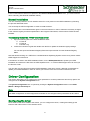
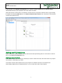
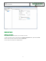
7TTCP Generic TCP/IP Driver 7TTCP Generic TCP/IP Driver User Manual Schneider Electric Denmark A/S Schneider Electric IGSS-Automation Lautrupvang 1 DK-2750 Ballerup, Denmark Phone: +45 88 30 20 00 www.schneider-electric.com VAT no. DK 73 63 41 13 Disclaimer The information provided in this documentation contains general descriptions and/or technical characteristics of the performance of the products contained therein. The documentation is not intended as a substitute for and is not to be used for determining suitability or reliability of these products for specific user applications. It is the duty of any such user or integrator to perform the appropriate and complete risk analysis, evaluation and testing of the products with respect to the relevant specific application of use thereof. Neither Schneider Electric nor any of its affiliates or subsidiaries shall be responsible or liable for misuse of the information contained herein. The information contained herein is the property of Schneider electric and is supplied without liability for errors or omissions. If you have any suggestions for improvements or amendments or have found errors in this publication, please notify us. No part of this document may be reproduced in any form or by any means, electronic or mechanical, including photocopying, without express written permission of Schneider Electric. All pertinent state, regional and local safety regulations must be observed when installing and using this product. For reasons of safety and to help ensure compliance with documented system data, only the manufacturer should perform repairs to components. Failure to use Schneider Electric software or approved software with our hardware products may result in injury, harm or improper operating results. Failure to observe this information can result in injury or equipment damage. ©2004, 2015, Schneider Electric, All rights reserved. Schneider Electric IGSS-Automation Lautrupvang 1 DK-2750 Birkerød, Denmark Phone: +45 88 30 20 00 www.schneider-electric.com VAT no. DK 73 63 41 13 2 7TTCP Generic TCP/IP Driver Contents Disclaimer .......................................................................................................................................................... 2 Introduction ........................................................................................................................................................ 4 Driver Files .............................................................................................................................................. 4 Software Requirements ........................................................................................................................... 4 Hardware Requirements ......................................................................................................................... 4 Installation .......................................................................................................................................................... 5 Automatic Installation .............................................................................................................................. 5 Manual Installation................................................................................................................................... 6 Driver Configuration ........................................................................................................................................... 6 Configuring the driver .............................................................................................................................. 6 Adding new PLC machines ..................................................................................................................... 7 Node Parameters .................................................................................................................................. 10 Testing the connection .......................................................................................................................... 10 Specific Driver Installation ............................................................................................................................... 10 PLC Setup ............................................................................................................................................. 10 Object Configuration ........................................................................................................................................ 11 Format of messages ........................................................................................................................................ 12 Input message ....................................................................................................................................... 12 Output message .................................................................................................................................... 13 Performance and Throughput .......................................................................................................................... 14 Error Codes ..................................................................................................................................................... 14 3 7TTCP Generic TCP/IP Driver Introduction This document describes how to set up and troubleshoot the IGSS 7TTCP Interface Driver. The IGSS program must be installed as an IGSS Server on the machine which is to be the IGSS Server and a functioning network of personal computers and PLC machines must be in place prior to installing and configuring the driver. The driver implements the IGSS IP stack over TCP. Driver Files The following files are used set up and troubleshoot the IGSS 7TTCP interface driver: 7TTCP.DLL: Contains the protocol stack required for communication with PLCs using ethernet TCP/IP interfaces. 7TTCP.DLL: Contains the graphical user interface used to configure the 7TTCP interface driver. COMMDRV.REG: Contains the required information which must be correctly updated in the Windows registry in order for the IGSS program to make use of the driver. The files are usually located in the GSS folder of the IGSS installation. Default IGSS installation folder: The default IGSS installation folder is: For 32-bit machines: C:\Program Files\Schneider Electric\IGSS32\<IGSS Version> For 64-bit machines: C:\Program Files (x86)\Schneider Electric\IGSS32\<IGSS Version> If you have installed IGSS Version 11, the <IGSS Version> folder name will be V11.0. Software Requirements The 7TTCP interface driver is designed to be used with IGSS version 11 or higher. The 7TTCPdriver uses the standard Microsoft TCP/IP protocol stack. The protocol is normally installed in all Microsoft operating systems and can be used as it is. DNS and other support protocols are not used by the driver and do not need to be installed or configured. The 7TTCPdriver uses the ISO transport layer on top of the TCP/IP protocol as it is defined in the RFC. This means the TCP/IP port must be accessible and opened for use. If you are employing a firewall, please be aware that the port used for TCP/IP communication must be open for bi-directional connections. If the network addresses from the IGSS program to the PLC machines include more firewall, all of these must be configured correctly to allow bi-directional TCP/IP communication. Hardware Requirements The 7TTCP interface driver requires a standard Ethernet Network Interface Controller (NIC) interface with TCP/IP (UDP/IP) installed in the PC which contains the IGSS program. The IGSS Generic TCP/IP driver can connect with the following PLC machines: 4 7TTCP Generic TCP/IP Driver An Ethernet port supporting TCP/IP (UDP/IP) is required on the PLC machines. Please refer to the PLC documentation supplied by the PLC producer for cable, setup and wiring instructions. Installation The IGSS 7TTCP Interface Driver is assigned the Driver ID 34 in the IGSS program and is displayed in the System Configuration form where it can be selected when setting up the IGSS configuration. Once the IGSS program has been installed on the IGSS Server machine and the IGSS Master has been started, the configuration which is to use the 7TTCP interface driver can be opened in the IGSS Master and set up in the System Configuration form. Automatic Installation The driver is normally installed when IGSS is installed. To verify that the driver has been installed correctly, open the System Configuration form. In the left pane of the System Configuration form, select an IGSS station and click Edit > New Driver (or right-click the station and select New Driver) The 7TTCP interface driver (Driver ID 34) should be found in the list of available drivers in the Select Communication Driver form. If the 7TTCP interface driver is present in the Select Communication Driver form, you can proceed to the Driver Configuration chapter. 5 7TTCP Generic TCP/IP Driver If the 7TTCP interface driver is not present in the Select Communication Driver form, you must install the driver manually. (See Manual Installation below) Manual Installation You can manually install the 7TTCP interface driver if it is not present in the IGSS installation by following the process described below. You must stop the IGSS configuration in order to install the driver. You must also have Local Administrator rights on the local machine in order to make the necessary changes to the machine registry as well as update files in the Program Files folders, if that is where IGSS has been installed. To manually install the 7TTCP interface driver 1. Copy the following files to the IGSS installation folder: a. 7TTCP.dll b. 7TTCP.dll c. CommDrv.reg 2. Locate the CommDrv.reg file and double-click the file to update the windows registry settings. You can also open the Windows Registry Editor and import the file from the Windows Registry Editor. Note that double-clicking on a .REG file in a 64 Bit Windows Operating System will not work, please contact IGSS Support for instructions If the files do not exist in the IGSS installation folder, run the IGSSUpdateClient to update your IGSS installation and retrieve the files from the IGSS Update server – or contact IGSS Support who can send you the files via e-mail. You can also copy the files from another IGSS installation of the same version, although it is advisable to update your IGSS installation in order to ensure you have the most recent versions of the driver files. Driver Configuration This section describes how to configure the driver parameters. All driver parameters and set up options are configured in the System Configuration form. The System Configuration form is opened by clicking the System Configuration button in the IGSS Master > Design and Setup tab. Note The IGSS configuration must be stopped and restarted for the configured driver parameters to take effect. Configuring the driver Once the driver has been added to the station, you can configure the driver, creating and setting up the interface and nodes of the 7TTCP interface driver. 6 7TTCP Generic TCP/IP Driver In the left pane of the System Configuration form, select the station (IGSS server or Operator Station with/Distributed Driver) and expand the driver list under the station. Select the Generic TCP/IP driver. If the Generic TCP/IP driver is not present, add the driver by right-clicking the station and selecting New Driver. In the Select Communication Driver form, select the 7TTCP Generic TCP/IP driver (Driver ID 34). Adding new PLC machines When a new PLC machine is added, you can add a new node representing the PLC to the driver in the left pane of the System Configuration form. Adding a new Interface Some drivers require you to create an interface per node to contain the node, and some drivers only require one interface, containing many nodes. The Generic TCP/TP Driver (Driver ID 34) only requires one interface and since an interface was automatically added when you added the driver, you can select the node in the left panel. 7 7TTCP Generic TCP/IP Driver Connection Types Adding a new Node After you have created a new interface, you can create a new node. To add a new node to a driver, in the left pane of the System Configuration form, right-click the 7TTCP interface under the Generic TCP/IP driver and select New Node. The new node will be created in the 7TTCP interface. 8 7TTCP Generic TCP/IP Driver Each new node is a new PLC driver, with first node being numbered 0. Naming Nodes (PLCs) in the System Configuration form You can add a unique name and description to the node in the Identification tab of the Node parameters in the right pane of the System Configuration form. Note that the node name will only be displayed in the System Configuration form and will not be displayed in the Edit Mapping tab of the Object Properties form in the Definition module Note The 7TTCP interface driver can support up to 8 nodes. After you have created the new node, you can configure the node, setting the required node options and parameters in the Node Properties, Identification and Advanced tab pages in the right pane of the System Configuration form. 9 7TTCP Generic TCP/IP Driver Node Parameters The following table describes some of the parameters you can define for the node. Field IGSS node number Description The node number which IGSS uses to reference a unique 7TTCPMON application or other node. This node number is required when binding an IGSS atom (tag) to a register in the 7TTCPMON application or the node. Any number from the drop down list can be used. TCP/IP Parameters Local IP Address Remote IP Address Local Socket number (port number) Remote Socket number (port number) Use keep alive… Only used for multihomed setups, and should normally be left empty. The IP address of the 7TTCPMON application or the node. Only used for multihomed setups, and should normally be left empty The port number of the 7TMONTCP application or the node. The default value is 12398. Activate keep alive messages if no scan or set output messages within 10 seconds. Testing the connection When the PLC and the IGSS Station machine are connected on a network and both are running, you can verify the IP address by using the PING command in a command prompt. See the example below. Example, in a command prompt C:\> ping 192.168.11.55 Note that some firewalls will not allow the ping command and the ping response. In these cases, the Ping command cannot be utilized for verification of the internet connection. Specific Driver Installation The following descriptions are based on one of many installation tools for the PLC. You can use other installation tools but be aware that each installation tool may differ from the others in specific areas. PLC Setup You must set up a connection for communication to IGSS in the PLC. Connection type It is also important to verify that any firewalls and other net connection-based security software permit TCP/IP communication through the defined port. 10 7TTCP Generic TCP/IP Driver Once you have set up the PLC and the Driver/Interface/Node properties in the System Configuration form in IGSS, you can start creating and addressing objects in the IGSS configuration to connect to the PLCs in order to send and retrieve data from them. Object Configuration Once the driver and the PLC nodes have been defined, IGSS Objects and Atoms can be linked to process variables in the PLC node. Various different types of PLC memory can be accessed for read/write operations using the driver. By using the Edit Mapping tab in the Object Properties form, you can specify the binding between the object’s atoms and the PLC process variables. Start by selecting an atom and select the 7TTCP interface driver in the “Driver” drop down list: Now select the desired PLC node number and continue by setting up PLC device addressing. Remember to specify the number (register number within the device type). 11 7TTCP Generic TCP/IP Driver Note that the corresponding Mnemonic is displayed and updated as you select the appropriate parameters. This is a help to make sure you always bind to the correct process variable. Continue this process for each atom on the object and save the parameters by clicking the OK button when finished. Format of messages The driver is using following data format for sending and receiving messages to and from the 7TTCPMON application or the connected nodes. Notice the lowest significant byte is in lowest number in Byte []. Input message This message is received by the driver 7TTCP and the data is send to the IGSS master. TCP Header Byte Byte [0..3] Description Length Byte [4..7] Length is the total length of the message with the number of bytes Opcode Opcode = 0 to indicate user data Opcode = 1 to indicate keep alive TCP Data Byte Byte [8..11] Description Node number Byte [12..15] The Node number in IGSS. The node number can be seen in the System Configuration form in the IGSS Master. Data group Data group is 0 at output message. Byte [16..19] At input message, value = 0 should be used. The driver 7TTCP only handles data group 0. Word offset Byte [20..23] The word offset for data group. Type Byte [24..27] Type = 1 read Type = 2 write. Word length of data Byte [28,29] Word length = number of words of data from data[0] to data[n] at type = 2, Word length = number of words to be read at type = 1. Data[0] Data is filled with the lowest significant byte in the lowest number in Byte []. If using Data type BYTE in the configuration of objects (See 3.1) the highest significant byte is set to 0. 12 7TTCP Generic TCP/IP Driver … Byte [n,n+1] … Data[n] Output message This message is send from IGSS to the specified node. TCP Header Byte Byte [0..3] Description Length Byte [4..7] Length is the total length of the message with the number of bytes Opcode Opcode = 0 to indicate user data Opcode = 1 to indicate keep alive TCP Data Byte Byte [8..11] Description Node number Byte [12..15] The Node number in IGSS. The node number can be seen in the System Configuration form in the IGSS Master. Data group Data group is 0 at output message. Byte [16..19] At input message, value = 0 should be used. The driver 7TTCP only handles data group 0. Word offset Byte [20..23] The word offset for data group. Type Byte [24..27] Type = 1 read Type = 2 write. Word length of data Byte [28,29] Word length = number of words of data from data[0] to data[n] at type = 2, Word length = number of words to be read at type = 1. Data[0] Data is filled with the lowest significant byte in the lowest number in Byte []. … Byte [n,n+1] If using Data type BYTE in the configuration of objects (See 3.1) the highest significant byte is set to 0. … Data[n] 13 7TTCP Generic TCP/IP Driver Performance and Throughput The driver is designed for maximum throughput on a LAN/WAN network. On a standard PC with a standard NIC you should expect a throughput of 20+ request/response cycles pr. second. Each PLC node is handled concurrent and independently. This means if you add more PLC’s to the system then the throughput pr. PLC should only be affected marginally provided that the PC/NIC throughput is sufficient. The IGSS communication engine optimizes communication throughput by seeking to group data whenever possible. Therefore if the communication engine is required to read e.g. DM0001 and DM0031 then it will read data registers DM0001, DM0002, … , DM0031 as a block. This is much more efficient than reading the two data registers using two separate read requests. Error Codes This section describes the error codes specific to the IGSS 7TTCP interface driver. While troubleshooting communication- or addressing problems the Driver Test Application might be useful to display error codes reported by the driver. The following table describes some of the possible 7TTCP error codes. Error Code 0x5501 Description Name: Example:_7TOMRTCP_DATA_BLOCK_TOO_BIG Cause: Example: User attempted to read or write a block of more than 256 items. Driver only allows up to 256 items in a block. 0x4001 Name: _7TTCP_BIND_SOCKET_FAILED Cause: Unable to open a stream socket Action: Check that WinSock is present Subcode: windows errorcodes 0x4002 Name: _7TTCP_BIND_SOCKET_FAILED Cause: Unable to bind to socket Action: Check if local IP address and port is used twice in the same configuration Subcode: windows errorcodes 0x4003 Name: _7TTCP_CONNECT_SOCKET_FAILED Cause: Unable to connect to remote node. Action: verify that the node IP Address and Port is correct and that it is online by pinging the device using the IP Address and Port supplied for the node in sysconfig. 14 7TTCP Generic TCP/IP Driver Subcode: windows errorcodes 0x4004 Name: _7TTCP_SEND_SOCKET_FAILED Cause: Unable to send requests to node. Action: verify that it is possible to ping the device Subcode: windows errorcodes 0x4005 Name: _7TTCP_RECV_SOCKET_FAILED_FF Cause: Session closed by remote node Action: None, the driver will try to reconnect. Subcode: windows errorcodes 0x4006 Name: _7TTCP_RECV_SOCKET_FAILED_00 Cause: Session closed by remote node Action: None, the driver will try to reconnect. Subcode: windows errorcodes 0x4007 Name: _7TTCP_RECV_NO_MSG Cause: Messagepool empty Action: Increase number of messages in Driver Setup 0x4008 Name: _7TTCP_RECV_MSG_TOO_LONG Cause: Message longer than 255 bytes received Action: Reduce segment size in remote server 0x4009 Name: _7TTCP_RECV_TIMEOUT 0x4009 Cause: node has not responded within the specified time. Action: None, driver will retry. If the problem persists please contact 7T Support. 15


![Multi Input Module for OverView D user`s manual [v07]](http://vs1.manualzilla.com/store/data/005713215_1-e2d53d24a0a93d32e9e353f3f6c133cd-150x150.png)