1
Imm und Bühler Elektronik
Specification
Multi Media Interfaceboard
MMIB
MMIB1E
DATA SHEET
MMIB1E
Multi Media Interface Board
The products and specifications are subject to change without notice.
Please ask for the latest releases to guarantee the satisfaction of your product requirements.
Imm und Bühler Elektronik
Maybachstrasse 10
D-76227 Karlsruhe
File: Data-MMIB1E-ENG.doc
Released: 02/2001
Page 1 of 41
Imm und Bühler Elektronik
Multi Media Interfaceboard
MMIB
Specification
MMIB1E
Contents
User Manual
1.
2.
2.1
2.2
2.3
2.4
Features
OSD menu and user controls
Hierarchical overview in VGA mode
Hierarchical overview in video mode
Rough overview
Detailed OSD description
3.
4.
5.
6.
6.1
6.2
6.3.
6.4.
7.
How to select your desired Display
Characteristics
Mechanical drawings
Connectors
Supply connectors
Input signal connectors
Peripheral connectors
Display connectors
Special Version
8.
8.1.
8.2.
8.3.
8.4.
RS232 communication
Hardware connection
RS232 protocol
Protocol examples
Item Numbers
9.
Software Revision History
Datasheet
RS232 Specification
10. Warrenty
11. Special applications
Appendix I: Keyboard and IR-Remote
File: Data-MMIB1E-ENG.doc
Released: 02/2001
Page 2 of 41
Imm und Bühler Elektronik
Specification
Multi Media Interfaceboard
MMIB
MMIB1E
1. Features
The MMIB1 interface board is designed for controlling Flat–Panel-Displays. The unit provides analog
video and VGA(PC) signals to TFT/LCD- and Plasma Displays.
VGA input (PC signals):
• Input connector: 15pol HD SubD
receptacle (R/G/B/Hsync/Vsync)
• VGA to SXGA/WXGA and an nearly
unlimited range of user resolutions
• Up to 140Mhz sample rate
• „Autoadjust“ function
• Multisync capability, due to frame rate
conversion, independent from type of
connected display
Video input:
• Input connectors: 2x Cinch (FBAS), 1x
Mini Din 4pol (SVHS Y/C)
• PAL-System with automatic recognition of
4:3, various letterboxes and 16:9 formats
• NTSC and SECAM coming soon
• 4H comp filter
• temporal deinterlacing and noise reduction
(‚Movie‘ mode)
• spatial deinterlaceing (‚Sport‘ mode)
• Horizontal anarmophic scaling/zoom
(Panorama View / Waterglass View)
Digital input:
• 24 bit RGB or 16bit YCrCb (4:2:2,4:1:1)
• and control signals
High-Performance-Scaling
• Full screen support for all input resolutions
independent of display resolution,
achieved by horizontal and vertical
independent magnification or downscaling
in real-time
Frame-memory
• Any input frame rate can be converted to
the desired output frame rate which is
recommended by the display manufacturer
•
Controlsignals for backlight, PLE, H/V
reverse, etc... (depends on display
features)
Universal:
• The MMIB1 interface-board is build for
running with all displays
• Since the display-adapter (see below)
decides which display is connected the
MMIB could shipped without knowing the
destination display.
• Recognition of the connected display is
done automatically
Other features:
• Control of brightness, contrast, sharpness
• advanced on screen display (Windows
„look and feel“)
• Help function
• Adjustable gammacorrection (in 10 steps
between 0.. 2.5)
• Keyboard with 5 keys, can be mounted
horizontal or vertical, includes IR receiver
for remote control
• Timer (especially for backlight MTBF)
Signal Managment and Autodetection
•
•
•
Input search at No Signal
Autodetection of New Signals at any input
Power On: Input selection.
Advanced Key features
• Input selection over several keys (toggling
or direct)
• User definable Hotkeys (Function-list)
Display output:
• Single and dual pixel port output (18/24,
36/48 bit) applied on 3.3V or 5V high level
• Up to 100Mhz pixel-rate
• Panel Vcc(depends on adapter) 3,3/5/12 V
• Asynchronous output timing in VGA mode,
optimized on Panel requirements
• Synchronous output timing on video mode
(50/60Hz), to avoid movement artifacts
File: Data-MMIB1E-ENG.doc
Released: 02/2001
Page 3 of 41
Imm und Bühler Elektronik
Specification
Multi Media Interfaceboard
MMIB
MMIB1E
2. OSD menu and user controls
All the functions of the interface board are selected and adjusted using an advanced on screen display
(OSD) and a keyboard or a IR-remote control. The OSD includes an online help window to explain the
functionality of the menu items.
The OSD menu of the MMIB is controlled via a 5 key (Up, Down, Left, Right and Ok) keyboard or
Remote.
Since we try to meet a lot of customer requirements there are a lot of ways to configure the keyboard
behavior while the OSD is closed.
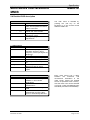
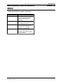
Functionality while OSD is closed (Default):
Key
UP
LEFT
RIGHT
DOWN
Function
Opens the SOURCE menu.
Opens the INFO menu
Opens the GEOMETRY menu
Toggles through the inputs
OK
Opens the MAIN menu.
Remark
Between which input the key toggles can be
selected (See OTHER->KEYBOARD OPTIONS>DOWN)
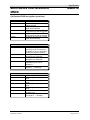
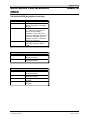
Functionality while OSD is closed (User adjustable):
Key
UP
LEFT
RIGHT
DOWN
OK
Function
nd
Activate the 2 functionlist.
No function
st
Activate the 1 functionlist
Toggles through the inputs
No function
st
Activate the 1 functionlist
Toggles through the inputs
No function
st
Activate the 1 functionlist
No function
Remark
see also description for menu item functionlist II
see also description for menu item functionlist I
Between which input the key toggles can be selected
see also description for menu item functionlist I
Between which input the key toggles can be selected
see also description for menu item functionlist I
All user adjustments for the keyboard are available in OTHER->KEYBOARD OPTIONS
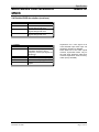
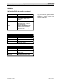
Functionality while OSD is open.
Key
UP
Function
Select the previous menu item. Wrap around is provided at
the first item of a menu.
LEFT
Decrease the actual selected value. Toggle ON/OFF
buttons. Select an OPTION button.
RIGHT
Increase the actual selected value. Toggle ON/OFF
buttons. Select an OPTION button.
Select the next menu item. Wrap around is provided at the
last item of a menu.
Close the active menu an return to the previous.
DOWN
OK
File: Data-MMIB1E-ENG.doc
Released: 02/2001
Remark
Page 4 of 41
Imm und Bühler Elektronik
Multi Media Interfaceboard
MMIB
Specification
MMIB1E
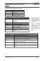
2. OSD menu and user controls (continue)
Note: Most adjustments are only possible while an input signal is applied.
Adjusted menu items will be saved if
• the sub menu is closed
• an other input format is detected
Since we try to support the customer with all the features possible by the hardware and of lot of
special requirements the OSD structure have become really large. So we have designed the OSD
structure straight in order of the logical appearance of a desired function.
Therefore always search a desired function in the logical orders:
MAIN->INPUT SIGNAL: Anything according to the input signal. Like selecting a input source, no
signal, newsignal settings.
MAIN->GEOMETRY. Anything according to the position and size (geometry). Also the geometry is
well structured:
MAIN->GEOMETRY->INPUT: Any parameter to descripe the incoming signal.
MAIN->GEOMETRY->DISPLAY: Additional parameters to descripe the actual display.
MAIN->GEOMETRY->ADVANCED: How to handle the incoming signal.
MAIN->PICTURE: All the paramters like contrast, brightness, colors and so on.
MAIN->OTHER: System settings like language, OSD position, keyboard options and so on.
File: Data-MMIB1E-ENG.doc
Released: 02/2001
Page 5 of 41
Imm und Bühler Elektronik
Multi Media Interfaceboard
MMIB
Specification
MMIB1E
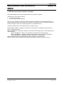
2.1 Hierarchical overview in VGA mode
File: Data-MMIB1E-ENG.doc
Released: 02/2001
Page 6 of 41
Imm und Bühler Elektronik
Multi Media Interfaceboard
MMIB
Specification
MMIB1E
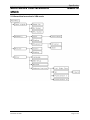
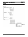
2.2 Hierarchical overview in video mode
File: Data-MMIB1E-ENG.doc
Released: 02/2001
Page 7 of 41
Imm und Bühler Elektronik
Specification
Multi Media Interfaceboard
MMIB
MMIB1E
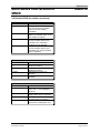
2.3 Rough overview
Function
Selecting an input signal the video
source and norm
What happens if no signal is
applied on the actual selected input
Menu(s)
main->input signal
main->input signal-sources
UP-KEY
main->input signal->No Signal
What happens on power up
main->input signal->Power On
While watching video a PC signal is main->input signal->Auto
applied
Picture position is wrong adjusted
main->geometry
The picture looks like lines are
displayed in an wrong order
main->geometry
main->geometry->interlaced
The picture look dark
main->picture
OSD language
OSD style and position
main->other->language
main->other->OSD setup
How long is the display running
main->other->runtime
info->maintanance
main->other->keyboard options
Whats about hot-keys ?
Remark
VGA, Composite input, svideo input
terrestrical, satellite, vcr,
PAL, NTSC, SECAM
Background Color
Text
Search another input
Supervision of none selected
inputs is possible.
Phaseshift
Samplerate
Position
Resolution
Interlaced
ODD / EVEN
spartial deinterlacing
temporal deinterlacing
static mesh
brightness, contrast, R G B,
backlight dimming
cascade, transparent,
position, color
main->other->keyboard
options->funtionlist I
Not everyone should have access
to the OSD menu.
File: Data-MMIB1E-ENG.doc
Released: 02/2001
main->other->keyboard
options->funtionlist II
main->other->keyboard options
LEFT RIGHT DOWN
UP
OK
Page 8 of 41
Imm und Bühler Elektronik
Multi Media Interfaceboard
MMIB
Specification
MMIB1E
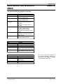
2.4 Detailed OSD description
1. Mainmenu
Item
Input
1.1
Geometry
Picture
1.2
1.3
1.4
Other
1.5
1.1 Input source
Item
VGA
Comp 1
Comp 2
S-video
Power On
1.1.2
1.1.3
1.1.4
1.1.5
No Signal
1.1.6
Auto
1.1.7
Function
Choose the input signal out of
VGA, 2X Composite and SVHS
Video connectors.
Adjust frame offset, output
format and zoom function.
Adjust brightness, contrast,
sharpness, colors.
Change language and OSD
adjustments.
The main menu is selected by
pressing the ‚OK‘ key on the
keyboard or on the remote control
while the OSD is off.
Function
Show VGA input signal, the
resolution and the H and V
frequency of the input signal are
displayed
st
Show 1 composite input signal
nd
Show 2 composite input signal
Show SVHS input signal
Which input is select at power
up.
Several options to define
behavior at loss of signal.
Supervision of none selected
inputs.
1.1.2 Source (1.1.3, 1.1.4)
Item
Function
Satellite
Optimized color recovery for
satellite TV and Camera
applications
Terrestrical
Optimized color recovery for
terrestrical TV
Video recorder
Optimized color recovery for
VCR
Norm
Select Video norm, if AUTO is
selected the incoming video
norm is automatically detected.
File: Data-MMIB1E-ENG.doc
Released: 02/2001
Every video source has a delay
between
the
luminance
and
chrominance information in the
video signal. Select the desired
source for optimized color recovery.
Also the video norm can be selected
out of PAL, NTSC and SECAM color
standards (and their sub-standards).
Page 9 of 41
Imm und Bühler Elektronik
Multi Media Interfaceboard
MMIB
Specification
MMIB1E
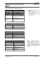
2.4 Detailed OSD description (continue)
1.1.5 Power On
Item
Default
VGA
COMP1
COMP2
S-video
1.1.6 No Signal
Item
Search
1.1.6.1
Blue
Black
User
1.1.6.2
Text
1.1.6.1 Search
Item
VGA
COMP 1
COMP 2
S-video
Delay
Text
Function
At power up the last active input
will be selected.
At power up always the VGA
input will be selected.
st
At power up always the 1
composite input will be selected.
nd
At power up always the 2
composite input will be selected.
At power up always the s-video
input will be selected.
Function
If no signal is applied on the
actual input. All out of the four
available inputs can separately
enabled for signal searching.
if no signal is applied a blue
background is displayed.
if no signal is applied a blue
background is displayed.
if no signal is applied a color
adjustable by the user is
displayed.
Enables or disables the “No
signal on...” messange.
Function
Allows signal searching on this
input.
Allows signal searching on this
input.
Allows signal searching on this
input.
Allows signal searching on this
input.
Delay time between changing to
another input
Enables or disables the “Search
for signal on...” message.
File: Data-MMIB1E-ENG.doc
Released: 02/2001
Page 10 of 41
Imm und Bühler Elektronik
Multi Media Interfaceboard
MMIB
Specification
MMIB1E
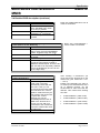
2.4 Detailed OSD description (continue)
1.1.6.2 User color
Item
Red
Green
Blue
1.1.7 Auto
Item
VGA
Comp 1
Comp 2
S-video
Back
Function
Red color component for no
signal background color.
Green color component for no
signal background color.
Blue color component for no
signal background color.
Function
Show VGA input signal, the
resolution and the H and V
frequency of the input signal are
displayed
st
Show 1 composite input signal
nd
Show 2 composite input signal
Show SVHS input signal
Supervision of none selected
inputs.
File: Data-MMIB1E-ENG.doc
Released: 02/2001
Supervision for a new signal at an
none selected input Each input can
separately enabled or disabled.
Note: While one of the video inputs
is active, supervision works only for
the VGA input. While the VGA input
is active supervision works for every
video input (if enabled).
Page 11 of 41
Imm und Bühler Elektronik
Multi Media Interfaceboard
MMIB
Specification
MMIB1E
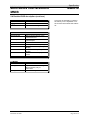
2.4 Detailed OSD description (continue)
1.2 Frame geometry for VGA
Item
Function
Input
1.2.1
All parameters which defines the
input format.
Display
1.2.2
Active display area definition
Advanced 1.2.3
Choose display modes:
standard, original, zoom
1.2.1 Input geometry
Item
Function
Pixelrate
Adjust pixelrate until the whole frame appears
the same. Hint : Use windows Shut Down
Picture
for adjustment.
Phaseshift
Adjust phaseshift to get best picture quality.
X-position
Adjust horizontal frame offset
Y-position
Adjust vertical frame offset.
Pixel
Number of active pixels of the incoming PC
signal. e.g. SXGA: 1280.
Lines
Number of active lines of the incoming PC
signal. e.g. SXGA: 1024.
Interlaced 1.2.1.1 Some adjustments for interlaced input signals
Auto
Automatic adjustment of the geometry
parameters.
1.2.1.1 Interlaced
Item
Non-Interlaced
Interlaced-Odd
Interlaced-Even
HV-Phase
PC
Sport
Movie
This menu can be
selected directly by
pressing the right key
on the keyboard or on
the remote control while
the OSD is off.
Note
for
interlaced
signals:
The
most
critical function is the
synchronization to the
desired field (odd or
even). Therefore the
right field should be
selected
(see
next
menu).
Function
Selection for non-interlaced input formats
Interlaced input format selection. Sampling starts with the odd frame.
Interlaced input format selection. Sampling start with the even frame.
Adjust counting delay for field detection. In some cases this item
should be enabled for a correct field detection.
Optimized de-interlacing for PC-Signals (static mesh). Fieldsynchronization is done one time if the actual (interlaced) format is
attached and on every key stroke.
Optimized de-interlacing for fast moving RGB video signals (temporal
de-interlacing). Field-synchronization is done continuously (about 10
fields).
Optimized de-interlacing for less moving RGB video signals (spatial
de-interlacing). Field-synchronization is done continuously (about 10
fields).
File: Data-MMIB1E-ENG.doc
Released: 02/2001
Page 12 of 41
Imm und Bühler Elektronik
Multi Media Interfaceboard
MMIB
Specification
MMIB1E
2.4 Detailed OSD description (continue)
1.2.2 Display
Item
Pixel
Lines
X-offset
Y-offset
Function
Number of active display pixel
per line. Maximum possible
value is the true display
resolution.
Number of active display lines.
Maximum possible value is the
true display resolution.
Output: if active display area is
chosen smaller than its real
resolution, the horizontal
position can be adjusted.
Output: if active display area is
chosen smaller than its real
resolution, the vertical position
can be adjusted.
File: Data-MMIB1E-ENG.doc
Released: 02/2001
Page 13 of 41
Imm und Bühler Elektronik
Multi Media Interfaceboard
MMIB
Specification
MMIB1E
2.4 Detailed OSD description (continue)
1.2.3 Advanced
Item
Standard
Original
1.2.3.1
Zoom
1.2.3.2
Function
In every case the input signal
will be displayed on the whole
display.
The input frame will be displayed
1:1. If the input resolution is
larger than the display
resolution, only a part of the
picture is displayed. If the input
resolution is smaller than the
display resolution, a window is
placed in the display.
Magnification of the input frame,
especially useful for display
walls.
1.2.3.1 Original (VGA)
Item
Function
X-Offset
Adjust X-position of the
displayed window.
Y-Offset
Adjust Y-position of the
displayed window.
1.2.3.2 Zoom (VGA)
Item
X-Offset
Y-Offset
X-Factor
Y-Factor
Function
Adjust X-position of the
displayed window.
Adjust Y-position of the
displayed window.
Magnification factor in Xdirection
Magnification factor in Ydirection
File: Data-MMIB1E-ENG.doc
Released: 02/2001
Page 14 of 41
Imm und Bühler Elektronik
Multi Media Interfaceboard
MMIB
Specification
MMIB1E
2.4 Detailed OSD description (continue)
1.3 Frame geometry (video)
Item
Function
Standard
Normal display of video input.
Zoom 1
Slightly zoomed picture to
reduce black lines at the
borders.
Zoom 2
As zoom 1, but more zoomed.
User Format 1.3.1 Manual adjustments for the
picture geometry, only for
special purposes.
Sport
Selects de-interlacing with
reduced moving artifacts.
Film
Selects de-interlacing with
reduced noise.
This menu can be selected directly
by pressing the right key on the
keyboard or on the remote control
while the OSD is off.
1.3.1 User format (video)
Item
Function
Input
1.3.1.1 Adjust position width., etc.
Display
1.3.1.2 Definition of the active display
area
Zoom
1.3.1.3 Input frame magnification
Format
1.3.1.4 Adjust the frame format
correction factors
1.3.1.1 Input (video)
Item
Function
Pixel
Number of pixel of the incoming
video signal.
Lines
Number of lines of the incoming
video signal.
X-position
Adjust horizontal frame offset
Y-position
Adjust vertical frame offset
File: Data-MMIB1E-ENG.doc
Released: 02/2001
Page 15 of 41
Imm und Bühler Elektronik
Multi Media Interfaceboard
MMIB
Specification
MMIB1E
2.4 Detailed OSD description (continue)
1.3.1.2 Display (video)
Item
Function
Pixel
Number of active display pixel
per line. Maximum possible
value is the true display
resolution.
Lines
Number of active display lines.
Maximum possible value is the
true display resolution.
X-offset
Output: if active display area is
chosen smaller than its real
resolution, the horizontal
position can be adjusted.
Y-offset
Output: if active display area is
chosen smaller than its real
resolution, the vertical position
can be adjusted.
1.3.1.3 Zoom (video)
Item
Function
X-Offset
Adjust X-position of the
displayed window.
Y-Offset
Adjust Y-position of the
displayed window.
X-Factor
Magnification factor in Xdirection
Y-Factor
Magnification factor in Ydirection
1.3.1.4 Format (video)
Item
Function
Auto adjustment
Automatically recognition of
PAL, PAL +, 4:3 or letterbox
pictures.
Parameter 1
Format correction achieved by
adding black lines or columns.
Parameter 2
Format correction achieved by
cropping lines or columns.
Parameter 3
Format correction achieved by
panorama or waterglass view.
File: Data-MMIB1E-ENG.doc
Released: 02/2001
Page 16 of 41
Imm und Bühler Elektronik
Multi Media Interfaceboard
MMIB
Specification
MMIB1E
2.4 Detailed OSD description (continue)
1.4 Picture
Item
Brightness
Contrast
Gammacorrection
Sharpness
Colors
1.4.1
Display
1.4.2
1.4.1 Colors
Item
Red
Green
Blue
Bandwidth
Compensation
1.4.2 Display
Item
Backlight
Dithering
L/R
U/D
Function
Brightness of the displayed
Picture, Default is 32
Contrast of the displayed
Picture, Default is 32
Compensation of the color
difference from TFT to CRT
displays.
Remark: the default value is
about 8.
Adjust sharpness enhancement
in Video mode (Vertical
peaking). Adjust scaling
algorithm for upscaling in VGA
mode
Select color temperature by
adjusting red, green and blue
RGB offsets.
Adjust backlight brightness and
display specific features.
Function
Color offset for red channel
Color offset for green channel
Color offset for blue channel
Input bandwidth selection to
reduce noise (video mode only)
Color carrier bandwidth
compensation (video mode only)
Function
Adjust backlight brightness
Color depth enhancement for 6
Bit Displays
Picture is mirrored left/right
Picture is mirrored up/down
File: Data-MMIB1E-ENG.doc
Released: 02/2001
The items of this menu depend on
the connected Display. Normally all
functionality the displays provides
are supported in this menu.
Page 17 of 41
Imm und Bühler Elektronik
Multi Media Interfaceboard
MMIB
Specification
MMIB1E
2.4 Detailed OSD description (continue)
1.5 Others
Item
Language
1.5.1
OSD Setup
1.5.2
Freeze mode
Help
Runtime
1.5.3
Keyboard
options
1.5.4
1.5.1 Language
Item
English
Deutsch
1.5.2 OSD setup
Item
Cascade Menus
Transparency
Standard colors
X-position
Y-position
Function
Select OSD language
Select OSD settings
Generate still picture
Switch OSD help function on/off
Show runtime of display and
backlight. Remark: the runtime
of the backlight can be reset in
the MTBFs menu.
Several options for the key
functionality while the OSD is
off.
In keyboard option there are a lot of
possibilities like:
• Enable or disable specific keys
• Create functionlists for most
needed menu items.
• Input selection can be enabled
for several keys.
Function
Select English language for
OSD
Select German language for
OSD
Function
Select cascaded menus
Select transparent OSD
Select between two OSD color
settings
Horizontal placement of OSD
Vertical placement of OSD
1.5.4 Keyboard options
Item
Function
Up
1.5.4.1 Options for the UP key
Left Right
1.5.4.2 Options for the Left and Right
key
Down
1.5.4.3 Options for the Down key
OK disabled
Disabled the OK key if
selected
Functionlist I 1.5.4.4 Create or Delete the first
functionlist
Functionlist II 1.5.4.5 Create or Delete the second
functionlist
File: Data-MMIB1E-ENG.doc
Released: 02/2001
Note: it is possible to define a
condition where the OSD is not
longer accessable by the keys. In
this case the OSD can be reached
only once more with the IR-Remote.
So ensure that the OK key always is
enabled if this condition is not
desired.
Page 18 of 41
Imm und Bühler Elektronik
Specification
Multi Media Interfaceboard
MMIB
MMIB1E
2.4 Detailed OSD description (continue)
1.5.4.1 Options for the UP key
Item
Function
Default
The default function open the
INPUT SOURCE menu when
the UP key is pressed
Functionlist II
If selected the UP key
nd
activates the 2 functionlist.
Disabled
No functionality while the OSD
is closed.
Refer also FUNCTIONLIST II how to
create a functionlist.
1.5.4.2 Options for the Left and Right key
1.5.4.3 Options for the Down key
Item
Function
Default
LEFT: Open the menu INFO
RIGHT: Open the menu GEOMETRY
DOWN: Toggles through the inputs.
st
Functionlist I
If selected the key activates the 1
functionlist,
Disabled
No functionality while the OSD is closed.
Inputs
Also this keys can select or toggle
through the input signals. Enable or
disable the desired inputs. There are two
input sets which can separately selected.
One for the DOWN key and one for the
Left and Right Keys
1.5.4.4 Functionlist I
1.5.4.5 Functionlist II
Item
Create
Delete
Function
Press left or right to enter the
create mode. The OSD
automatically restart with the
main menu. Now you can
move through the whole OSD
menu structure as in normal
operation. Select the item you
want to add to the function list
and press left. A short
message give you the
acknowledge that the item is
added to the function-list. In
this way you can add up to
seven items to the functionlist.
To quit the create mode close
the OSD menu.
Deletes the function-list.
File: Data-MMIB1E-ENG.doc
Released: 02/2001
Refer also FUNCTIONLIST I
how to create a functionlist.
After creating a function-list you
must connect the function-list to the
desired key (see submenus 1.5.4.1
– 1.5.4.3).
Please note: Depending if a video or
an VGA input is selected there are a
lot of different function. So the
function-lists for video and VGA are
different. This means there existing
four lists:
•
•
FUNCTIONLIST I (VGA mode)
FUNCTIONLIST I (Video mode)
•
•
FUNCTIONLIST II (VGA mode)
FUNCTIONLIST II (Video mode)
Page 19 of 41
Imm und Bühler Elektronik
Multi Media Interfaceboard
MMIB
Specification
MMIB1E
2.4 Detailed OSD description (continue)
2. Info
Item
Infos
MTBFs
2.1
2.2
2.1 Infos
Item
Interfaceboard
Paneladapter
Software Rev
Panelclock
Panel H
Panel V
Colors
Panelmode
2.2 MTBFs
Item
Backlight MTBF
Backlight reset
Function
Show information’s
Adjust/reset backlight MTBF
This menu is selected by pressing
the left key on the keyboard or on
the remote control while the OSD is
off.
Function
Show current version of the
interface-board
Show current version of the
paneladapter
Show software release number
Show panelclock frequency
Show horizontal frequency of the
display
Show vertical frequency of the
display
Show maximum displayable
colors
Show single/double pixel mode
Function
Adjust MTBF of the backlight.
Not functional, only to
remember.
Set the backlight runtime to 0
File: Data-MMIB1E-ENG.doc
Released: 02/2001
Page 20 of 41
Imm und Bühler Elektronik
Multi Media Interfaceboard
MMIB
Specification
MMIB1E
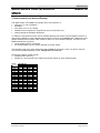
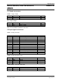
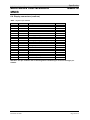
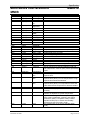
3. How to select your desired Display
The digital output of the MMIB very flexible due to free selection of:
• Timing (H / V / DE / polarities)
• Resolution
• Port width (18 / 24 / 36 / 48 Bit)
• Additional control signals are supported by the microcontroller unit.
• Analog voltage for Backlight adjustment.
To satisfy the requirements of the various available Displays we support various adapter-boards for a
wide range of Displays. These adapter-boards placed on the top of the MMIB board. Additionally every
adapter-board has a DIL-switch which allows to select one out of fifeteen Displays. At power on, the
MMIB automatically recognize:
• which adapter-board is connected
• the desired display via the number selected by the DIL-switch.
At first please refer to the order information (INFO-MMIB1E) document. There you get an overview
over all actual adapted Displays. Refer Adapterset overview table.
Select via the display model number:
• Adapterset No. (ASxx-xx)
• Display No. (This number has to select with the DIL-Switch on each adapter-board)
Display
No
00
01
02
03
04
05
06
07
08
09
10
11
12
13
14
15
DIP-SWITCH
1
2
OFF
OFF
ON
OFF
OFF
ON
ON
ON
OFF
OFF
ON
OFF
OFF
ON
ON
ON
OFF
OFF
ON
OFF
OFF
ON
ON
ON
OFF
OFF
ON
OFF
OFF
ON
ON
ON
3
OFF
OFF
OFF
OFF
ON
ON
ON
ON
OFF
OFF
OFF
OFF
ON
ON
ON
ON
File: Data-MMIB1E-ENG.doc
Released: 02/2001
4
OFF
OFF
OFF
OFF
OFF
OFF
OFF
OFF
ON
ON
ON
ON
ON
ON
ON
ON
Page 21 of 41
Imm und Bühler Elektronik
Specification
Multi Media Interfaceboard
MMIB
MMIB1E
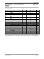
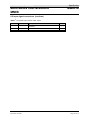
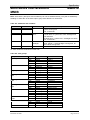
4. Characteristics
Symbol
VCC
Ivcc
Parameter
supply voltage
supply current (without display and
backlight)
Vin_video
(p-p)
Vin_vga (pp)
Visync
Ri
input video signal voltage (peak to
peak)
input video signal voltage (peak to
peak)
input sync signal voltage, for VGA
signals
input signal termination
Fclk
B
sampling rate for VGA signals
analog bandwidth for VGA signals
Tcom
Tind
commercial operating temperature
industrial operating temperature
L
W
H
Hadp
Hmo
Length
Width
Height
Mounting height for adapter boards
Mounting height for MMIB above
mounting plane
Ifuse
Fuse.
Condition
Min.
9
@12V
Typ.
12
400
Max.
15
1
V
0.7
V
3.3
5
V
75
Ohm
400
Mhz
Mhz
140
3dB
Unit
V
mA
-10
-40
65
80
°C
°C
132
142
20
13.8
mm
mm
mm
mm
mm
1.25
A
4
Proper ESD precautions are recommended to avoid performance degradation or loss of functionality.
File: Data-MMIB1E-ENG.doc
Released: 02/2001
Page 22 of 41
Imm und Bühler Elektronik
Multi Media Interfaceboard
MMIB
Specification
MMIB1E
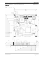
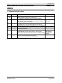
5. Mechanical drawings
File: Data-MMIB1E-ENG.doc
Released: 02/2001
Page 23 of 41
Imm und Bühler Elektronik
Specification
Multi Media Interfaceboard
MMIB
MMIB1E
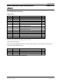
6. Connectors
Symbol
CON1
CON2
CON3
CON4
CON5
X2
JP20
Type
HDSUB15 receptacle
4-pin S-video (Mini Din)
Chinch receptacle
Chinch receptacle
JP17
SV9
SV2
Pin header 4pins, single row
Box type pin header 16pins
Box type pin header 20pins
Description
PC signal input
S-video (Y/C) input
st
1 Composite input
nd
2 Composite input
power supply
power supply
rd
3 Composite input, active
video output (composite)
Serial input (RS232)
Keyboard
VGA input extension
JP1
Pin header 2pins, single row
Flash Chip Select
JP16
Pin header 16 pins, double row
Display and backlight control
JP21
Pin header 30 pins, double row
Digital Output PORTB
JP22
Pin header 40 pins, double row
Digital Output PORTA
CON7
CON8
DF9-31S
DF9-31S
1 Digital input
nd
2 Digital input
Pin header 3pins, single row
File: Data-MMIB1E-ENG.doc
Released: 02/2001
st
Remark
not used
see ADP232P00
e.g for Composite
Board
must always be
closed
connector for display
specific adapter board
connector for display
specific adapter board
connector for display
specific adapter board
reserved for further use
reserved for further use
Page 24 of 41
Imm und Bühler Elektronik
Specification
Multi Media Interfaceboard
MMIB
MMIB1E
6.1 Supply connectors
CON5 – Supply voltage
Pin No.
1(center)
2(outer)
Symbol
VCC
GND
Description
Supply voltage
Ground
Level
9..15V
Description
Ground
Supply voltage
Level
X2 – Supply voltage
Pin No.
1
2
Symbol
GND
VCC
9..15V
Note: X2 and CON5 are parallel to each other.
6.2 Input signal connectors
CON1 – Analog VGA input
Pin No.
1
2
3
4
5
6
7
8
9
10
11
12
13
14
15
Symbol
R
G
B
N.C.
N.C.
R gnd
G gnd
B gnd
N.C.
GND
reserved
N.C.
H sync
V sync
reserved
Description
Red video signal
Green video signal
Blue video signal
Level
0.7V(p-p)
0.7V(p-p)
0.7V(p-p)
Ground for red
Ground for green
Ground for blue
Common ground
reserved for DDC
Horizontal sync signal
Vertical sync signal
reserved for DDC
LVTTL/TTL
LVTTL/TTL
CON2 – Svideo (SVHS/YC) input
Pin No.
1
2
3
4
Symbol
GND
GND
Y
C
Description
Ground
Ground
Luminance
Chrominance
Level
1V(p-p)
0.3V(p-p)
CON3, CON4 – Composite video input
Pin No.
1(center)
2
Symbol
Composite
GND
Description
Composite video input
Ground
File: Data-MMIB1E-ENG.doc
Released: 02/2001
Level
1V(p-p)
Page 25 of 41
Imm und Bühler Elektronik
Specification
Multi Media Interfaceboard
MMIB
MMIB1E
6.2 Input signal connectors (continue)
rd
JP20 3 Composite input, active video output
Pin No.
1
2
3
Symbol
Vin4
GND
Cout1
Description
rd
3 Video input (not implemented in
software)
ground
Active video output (external buffer needed)
File: Data-MMIB1E-ENG.doc
Released: 02/2001
Level
1V(p-p)
1V(p-p)
Page 26 of 41
Imm und Bühler Elektronik
Specification
Multi Media Interfaceboard
MMIB
MMIB1E
6.3. Peripheral connectors
SV9 Keyboard
Pin No.
1
2
3
4
5
6
7
Symbol
TIIO2
GND
TIIO1
TIO0
TIIO0
TIN4
AD1
8
9
TIN3
AD0
10
11
12
13
14
15
16
TIN2
SCL
TIN1
SDA
TIN0
U5
IRREC
Description
must be left open
Ground
Green LED, (LED is driven to GND)
I/O (for special customer requirements)
Red LED, (LED is driven to GND)
Input „OK“ key
Analog to Digital Converter Input (for special
customer requirements )
Input for „Right“ key
Analog to Digital Converter Input (for special
customer requirements).
Input for „Left“ key
Clock line for I2C-bus
Input for „Down“ key
Data line for I2C-bus
Input for „Up“ key
5V supply voltage
Input for infrared receiver diode
Level
TTL
TTL
TTL
TTL
TTL
0-5V
TTL
0-5V
TTL
TTL
TTL
TTL
TTL
TTL
Note: All key inputs are pulled up to VCC over 10k.
JP17 serial input (RS232)
Since Tx and Rx voltages are only on TTL level on this connector, JP17 should only used with the
ADP232Pxx RS232 adapter board.
Pin No.
1
2
3
4
Symbol
RXD0
TXD0
U5
GND
Description
Receive data line
Transmit data line
5V supply voltage for external adapter
Ground
Level
TTL
TTL
See also chapter 8: RS232 communication
File: Data-MMIB1E-ENG.doc
Released: 02/2001
Page 27 of 41
Imm und Bühler Elektronik
Specification
Multi Media Interfaceboard
MMIB
MMIB1E
6.4. Display connectors
Since the MMIB is recommended for use with display specific adapter boards, display and
backlight should not connected directly without advice from Imm & Bühler Elektronik.
JP16 Display and backlight control
Pin No.
1
2
3
4
5
6
7
8
9
10
11
12
13
14
15
16
Symbol
DA3
DOUT0
SCL
DOUT1
SDA
DOUT2
DINT0
TIO0
DIN2
DIO2
AD2
DIO3
AD3
DIN0
GND
DIN1
Description
Analog output
Output
Clock line for I2C
Output
Data line for I2C
Output
Input
I/O
Input
I/O
Analog input
I/O
Analog input
Input
Ground
Input
Level
0..5V
TTL
TTL
TTL
TTL
TTL
TTL
TTL
TTL
TTL
0..5V
TTL
0..5V
TTL
TTL
JP21 – Digital output PORTB
Pin No.
1
2
3..10
11
12
13..20
21
22
23..30
Symbol
U5
GND
PBR7..0
U3
GND
PBG7..0
U5
GND
PBB7..0
Description
5V supply voltage
Ground
Port B Red Data 7..0
3.3V supply voltage
Ground
Port B Green Data 7..0
5V supply voltage
Ground
Port B Blue Data 7..0
Level
3.3V CMOS
3.3V CMOS
3.3V CMOS
Attention: For pin numbers refer to drawing above. Numbering is inverse to box-type pin
headers.
File: Data-MMIB1E-ENG.doc
Released: 02/2001
Page 28 of 41
Imm und Bühler Elektronik
Specification
Multi Media Interfaceboard
MMIB
MMIB1E
6.4. Display connectors (continue)
JP22 – Digital output PORTA
Pin No.
1
2
3..10
11
12
13..20
21
22
23..30
31
32
33
34
35
36
37
38
39
40
Symbol
U3
GND
PAR7..0
U5
GND
PAG7..0
U3
GND
PAB7..0
U12
GND
DIO0
DA1
DIO1
DA2
PCLK
PDE
PVS
PHS
Description
3.3V supply voltage
Ground
Port A Red Data 7..0
5V supply voltage
Ground
Port A Green Data 7..0
3.3V supply voltage
Ground
Port A Blue Data 7..0
12V supply voltage (directly form input)
Ground
I/O
Analog output
I/O
Analog output
Display Clock
Data Enable
Vertical sync signal
Horizontal sync signal
Level
3.3V CMOS
3.3V CMOS
3.3V CMOS
TTL
TTL
3.3V
3.3V
3.3V
3.3V
CMOS
CMOS
CMOS
CMOS
Attention: For pin numbers refer to drawing above. Numbering is inverse to box-type pin
headers.
File: Data-MMIB1E-ENG.doc
Released: 02/2001
Page 29 of 41
Imm und Bühler Elektronik
Multi Media Interfaceboard
MMIB
Specification
MMIB1E
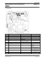
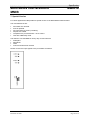
7. Special Version
For critical applications I&B provides a special version of the Multi Media Interface Board.
The main differences are:
•
•
•
•
•
•
All sockets are removed.
Fuse is replaced.
All connections be done by soldering.
All parts are coated.
Temperature is proved between –40°C to 80°C.
Coils are additionally clued.
This allows to use the MMIB on heavy duty environment like
• helicopters
• aeroplanes
• tanks
• marine and submarine vehicles
Please connect the input signals to the pin headers as follows:
File: Data-MMIB1E-ENG.doc
Released: 02/2001
Page 30 of 41
Imm und Bühler Elektronik
Specification
Multi Media Interfaceboard
MMIB
MMIB1E
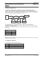
8. RS232 communication
The RS232 communication offers an additional way to adjust an control the OSD settings.
Therefore a simple RS232 protocol is used. Each data stream has a fixed length of 10 bytes.
To allow to connect more than one MMIB to the RS232 port of an host (e.g. personal computer) an
RS232 „ring“ technique is to use. Since RS232 is not recommended for more the two terminals each
client must repeat the incoming messages for the next client.
Host
RxD
RxD
RxD
TxD
TxD
TxD
1. MMIB
2. MMIB
Terminator
n. MMIB
For such applications Imm und Bühler Elektronik provides two type of RS232 adapters
ADP232P00: One SubD9 receptacle, provides up to 4 MMIBs. The Ring is done at the TTL side.
Termination can be done per jumper
ADP232P10: Like ADP232P00, but with two SubD9 receptacles. The ring can be build with standard
RS232 cable.
Recommended COM port
settings
Baud-rate
9600
Parity
Even
Data-bits
8
Stop-bits
1
Note: if you build up a session in a ring you should perform a “PING” command at first, to ensure that
all MMIB’s have a unique number.
8.1. Hardware connection
The connector JP17 has the following signals:
PIN
1
2
3
4
Signal
RX (TTL-Level)
TX (TTL-Level)
+5V (for external line driver)
GND
File: Data-MMIB1E-ENG.doc
Released: 02/2001
Page 31 of 41
Imm und Bühler Elektronik
Specification
Multi Media Interfaceboard
MMIB
MMIB1E
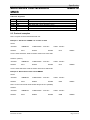
8.2. RS232 protocol
Standard read / write protocol:
<STARTC>
<MMIB-NO>
<CMD+ITEM> <VALUE>
2 bytes
1 byte
2 bytes
2bytes
<CKS><STOPC>
1byte 2 bytes
Communication lost or timeout
<STARTC>
<MMIB-NO>
<0xAAAA>
2 bytes
1 byte
2 bytes
<0xAA><0x0055>
1byte 2 bytes
protocol item
<STARTC>
<MMIB-NO>
value/range
0x55AA
0x00
0x01 .. 0xFF
<CMD+ITEM>
0x0 .. 0xF
Bit 15 .. 12
0x0 .. 0xFFF Bit 11 .. 0
<VALUE>
0x0000 ..
0xFFFF
0x0000
0x0001 ..
0xFFFF
<CKS>
<STOPC>
for items
which enable
or disable a
function
<0x5555>
2bytes
description
start condition
broadcast; transmission to all
MMIBs in the RS232 ring
transmission to the specific
MMIB
command (see table 8.1)
item to read/write (see table
8.3) or
keycode (see table 8.2)
or
transmission not for filesystem
access
value to be set / read
treated as
function will be / is disabled
function will be / is enabled
boolean
unsigned char
unsigned char
signed integer
signed integer
0x00 .. 0xFF
checksum
unsigned char
= (<MMIB-NO> + LOBYTE(<CMD+ITEM>) + HIBYTE(<CMD+ITEM>)+
LOBYTE(<VALUE>)+ HIBYTE(<VALUE>) ) AND 0xFF
0x00FF
stop condition from HOST
0x00FE
ACK stop condition form
CLIENT
0x0055
NACK stop condition from
CLIENT; communication was
lost or timeout has occurred
Table 8.1: commands
code
0x0
0x1
0x2
0x3
0x4
0x5
description
read, from client (MMIB) (see also CMD 0x4)
write, to client (MMIB) (see also CMD 0x4)
key, simulate keystroke on client (MMIB)
repeated key, simulate repeated keystroke on client (MMIB) (steps will be greater)
Save, necessary if items adjusted over CMD 0x0 and 0x1
ping, automatically numbering all clients (MMIB) in the RS232 ring (in physical order)
0xA
NACK (read only)
File: Data-MMIB1E-ENG.doc
Released: 02/2001
Page 32 of 41
Imm und Bühler Elektronik
Specification
Multi Media Interfaceboard
MMIB
MMIB1E
Table 8.2: keycodes
code
0x0B6
0x08B
0x0B7
0x08D
0x08C
description
left
up
right
down
ok
function while OSD is off
OSD starts with “input geometry” menu
OSD starts with “source menu”
OSD starts with “input geometry” menu
OSD starts with customer menu (if required)
OSD starts with “main menu”
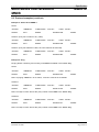
8.3. Protocol examples
Note: Lo Bytes should transmit/received first.
Example 1: Set Item 3 of MMIB 1 to a value of 0xFF
HOST:
<START>
<MMIB-No>
<CMD+ITEM> <VALUE>
0x55AA
0x01
0x1003
0x00FF
<CKS> <STOP>
0x13
0x00FF
at line: 0xAA 0x55 0x01 0x03 0x10 0xFF 0x00 0x13 0xFF 0x00
CLIENT: (returns)
<START>
<MMIB-No>
<CMD+ITEM> <VALUE>
0x55AA
0x01
0x1003
0x00FF
<CKS> <STOP>
0x13
0x00FE
at line: 0xAA 0x55 0x01 0x03 0x10 0xFF 0x00 0x13 0xFE 0x00
Example 2: Read value of Item 4 form MMIB 2
HOST:
<START>
<MMIB-No>
<CMD+ITEM> <VALUE>
0x55AA
0x02
0x0004
0x0000
<CKS> <STOP>
0x06
0x00FF
Note: at read commands value should always be zero (0x0000)
CLIENT:
<START>
<MMIB-No>
<CMD+ITEM> <VALUE>
0x55AA
0x02
0x0004
File: Data-MMIB1E-ENG.doc
Released: 02/2001
0x0500
<CKS> <STOP>
0x0B
0x00FE
Page 33 of 41
Imm und Bühler Elektronik
Specification
Multi Media Interfaceboard
MMIB
MMIB1E
8.3. Protocol examples (continue)
Example 3: Press OK at MMIB 1
HOST:
<START>
<MMIB-No>
<CMD+ITEM> <VALUE>
0x55AA
0x01
0x208C
<CKS> <STOP>
0x0000 0xAD
0x00FF
CLIENT: (if key has no effect to any value)
<START>
<MMIB-No>
<CMD+ITEM> <VALUE>
0x55AA
0x01
0x208C
<CKS> <STOP>
0x0000 0xAD
0x00FE
CLIENT: (if key has effected a value, the new value will be returned)
<START>
<MMIB-No>
<CMD+ITEM> <VALUE>
0x55AA
0x01
0x208C
<CKS> <STOP>
0x0500 0xB2
0x00FE
Example 4: Ping
Pinging allows numbering and counting of all MMIB’s available in the RS232 Ring
HOST:
<START>
<MMIB-No>
<CMD+ITEM> <VALUE>
0x55AA
0x00
0x5000
<CKS> <STOP>
0x5500 0xA5
0x00FF
Note: at pinging <MMIB-No> as no affect, <VALUE> must be set to 0x5500
CLIENT1:
<START>
<MMIB-No>
<CMD+ITEM> <VALUE>
0x55AA
0x00
0x5000
<CKS> <STOP>
0x5501 0xA6
0x00FE
Note: Low Byte of value returns the (new) number of the MMIB in the RS232 Ring.
CLIENT2:
<START>
<MMIB-No>
<CMD+ITEM> <VALUE>
0x55AA
0x00
0x5000
<CKS> <STOP>
0x5502 0xA7
0x00FE
Note: Low Byte of value returns the (new) number of the MMIB in the RS232 Ring.
File: Data-MMIB1E-ENG.doc
Released: 02/2001
Page 34 of 41
Imm und Bühler Elektronik
Specification
Multi Media Interfaceboard
MMIB
MMIB1E
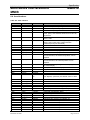
8.4. Item Numbers
Table 8.3: item numbers
itemno
004h
005h
006h
007h
00Dh
Menu
Source
Source
Source
Source
Input
Item
VGA
COMP 1
COMP 2
SVHS YC
Pixelrate
00Eh
Input
Pixel
00Fh
Input
Lines
010h
011h
012h
014h
015h
016h
Input
Input
Input
Display
Display
Display
X-Position
Y-Position
Phaseshift
Pixel
Lines
X-Offset
017h
Display
Y-Offset
018h
Advanced
Standart
019h
01Ah
021h
022h
023h
Advanced
Advanced
Picture
Picture
Picture
029h
02Ah
02Bh
02Ch
02Dh
02Eh
02Fh
030h
031h
03Ah
03Bh
045h
046h
047h
048h
049h
04Ah
04Bh
Picture
Input signal
Input signal
Original
Original
Zoom
Zoom
Zoom
Zoom
Language
Language
Source
Source
Source
Source
Source
Source
Source
Original
Zoom
Brightness
Contrast
Gammacorrect Compensation of the color difference from TFT to
ion
CRT displays. {Remark:} the default value is about
8.
Sharpness
H
V
X-Position
Horizontal position for scanning the input frame.
Y-Position
Vertical position for scanning the input frame.
X-Position
Horizontal positon for the magnified input frame.
Y-Position
Vertical positon for the magnified input frame.
X-Factor
Horizontal magnification factor.
Y-Factor
Vertical magnification factor.
Deutsch
English
Satellite
optimized color recovery for satellite TV.
Terrestrical
optimized color recovery for terrestrical TV.
Videorecorder optimized color recovery for VCR.
Satellite
optimized color recovery for satellite TV.
Terrestrical
optimized color recovery for terrestrical TV.
Videorecorder optimized color recovery for VCR.
Satellite
optimized color recovery for satellite TV.
File: Data-MMIB1E-ENG.doc
Released: 02/2001
description
Show VGA input signal.
Show 1st composite input signal.
Show 2nd composite input signal.
Show SVHS input signal.
adjust pixelrate until the whole frame appeares the
same. {Hint}: Use Windows Shut Down Picture for
adjustment.
Number of pixel of the incoming PC signal. For e.g.
SXGA: 1280.
Number of lines of the incoming PC signal. For e.g.
SXGA: 1024. Press OK to switch between
{interlaced} and {non-interlaced}.
Horizontal frame offset.
Vertical frame offset
Adjust phaseshift to get best picture quality.
Number of active display pixel per line.
Number of active display lines.
Output: if active display area is choosen smaller than
its real resolution, the horizontal position can be
adjusted.
Output: if active display area is choosen smaller than
its real resolution, the vertical position can be
adjusted.
In every case the input signal will be displayed on
the whole display.
The Input Frame will be displayed 1:1.
Magnification of the input frame.
Page 35 of 41
Imm und Bühler Elektronik
Specification
Multi Media Interfaceboard
MMIB
MMIB1E
04Ch
04Dh
04Eh
04Fh
050h
052h
053h
058h
059h
05Ah
05Bh
05Ch
05Dh
05Eh
05Fh
062h
Source
Source
Geometry
Geometry
Geometry
Geometry
Geometry
Input
Input
Input
Input
Display
Display
Display
Display
Format
063h
Format
Terrestrical
Videorecorder
Standart
Zoom 1
Zoom 2
Sports
Movie
Pixel
Lines
X-Position
Y-Position
Pixel
Lines
X-Position
Y-Position
Auto
adjustment
Parameter 1
064h
Format
Parameter 2
065h
Format
Parameter 3
067h
06Ah
06Bh
06Ch
06Dh
06Eh
Display
Zoom
Zoom
Zoom
Zoom
Geometry
084h
08Bh
08Ch
08Dh
09Dh
09Fh
Zoom
Colors
Colors
Colors
Display
OSD Setup
0A0h
0A1h
0B3h
0B4h
0B6h
OSD Setup
OSD Setup
OSD Setup
OSD Setup
Other
0B7h
Other
0BBh
Display
0BCh
Display
0BDh
0BEh
Display
Display
0BFh
Display
LCD-Backlight
X-Position
Y-Position
X-Factor
Y-Factor
User Format
define your own frame format. {Only for special
purposes.}
Zoom
Red
Green
Blue
Dithering
Cascade
Menus
X-Position
Y-Position
Transparency
Standart-colors
Freeze mode {Remark:} Adjustments in geometry or picture
parameter will clear freeze mode.
Help
Use{ up}, {down} to select an menu item. Use {left},
{right} to change the value or to reach the next
submenu. Use {ok} to go back to the previous menu
or to close the OSD.
Horizontal
reverse
Vertical
reverse
Backlight
Colorenhancm
ent
Horizontal
File: Data-MMIB1E-ENG.doc
Released: 02/2001
optimized color recovery for terrestrical TV.
optimized color recovery for VCR.
Optimized picture for fast moving frames.
Optimized picture for less moving frames.
Automatical recognition of Pal, Pal+, 4:3 or Letterbox
Pictures.
Format correction achieved by adding black lines or
columns.
Format correction achieved by cropping lines or
columns.
Format correction achieved by panorama or
waterglass view.
Page 36 of 41
Imm und Bühler Elektronik
Specification
Multi Media Interfaceboard
MMIB
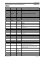
0DBh
0DCh
0DDh
0E2h
0E3h
0E4h
0EEh
0EFh
0F8h
0FEh
0FFh
104h
1EAh
1EBh
1ECh
1F5h
1F6h
1F7h
2F1h
reverse
View angle I
View angle II
Brightness
Colorenhancm
ent
Display
PLE
Brightness
Display
Backlight
Display
Dithering
Maintenance
Backlight
MTBF
Display
Backlight
Display
Dithering
Display
Rotate
Source
Norm
Source
Norm
Source
Norm
Colors
Bandwidth
Colors
Compensation
Response time Response time
D1040
Backlight
D1040
Night - OSD
Picture
Backlight
Display
Backlight
Display
H reverse
Picture
Rotate
Input signal
PC
Input signal
Sport
Input signal
Movie
Display
Odd-Even
2F6h
2F8h
Reduction
Reduction
2F9h
Reduction
2FAh
Reduction
3rd responce
time
2FBh
2FCh
D1040
D1040
Off
Manual
2FDh
D1040
Automatic
2FFh
D1040
Static mode
300h
D1040
Save
0C0h
0C1h
0C2h
0C3h
0C4h
0CFh
0D0h
0D5h
MMIB1E
Display
Display
Display
Display
File: Data-MMIB1E-ENG.doc
Released: 02/2001
Temperature
1st responce
time
2nd responce
time
Main time between failure for the backlight.
Response time for flicker reduction (manual)
Backlight-brightness
Enables dark colors for OSD
Adjust backlight brightness
Optimized picture for interlaced PC signals.
Optimized picture for fast moving frames.
Optimized picture for less moving frames.
Time (in minutes) for switching between Odd and
Even output lines. Value of {zero} means {interlaced}
output.
System-temperature which will switch to the 1st
response time.
System-temperature which will switch to the 2nd
response time. {Note:} For low temperatures a high
response time should be selected.
System-temperature which will switch to the 3rd
response time. {Note:} For temperatures below the
actual value the 4th response time will be activated.
No flicker reduction will be performed!
Flicker reduction {on}. The behavior can be adjusted
manually.
Flicker reduction {on}. The response time for the
reduction is depends on system-temperature.
{0:} automatic recognition of the input timing. {1..15:
Static mode:} Predefined geometry and picture
parameters. {Note:} If an {static mode} is active
adjustments will {not} be saved automatically.
Therefore use {save as static mode}
Save adjustments at the actual selected {static
mode}.
Page 37 of 41
Imm und Bühler Elektronik
Specification
Multi Media Interfaceboard
MMIB
MMIB1E
Note: Some items (like input source selectors) can not be disabled directly. They will be disabled by
enabling an other item in the same option group. See table 8.5 for such items.
Table 8.4: additional item numbers
itemno
800h
801h
High-word
Low-word
802h
803h
High-word
Low-word
804h
Item
System time
Backlight time
base
Reset
Backlight
description
Read only
System running time
Unit: 16 seconds
Read only
Counter state of system time when backlight time
was reset last.
Backlight time = system time – backlight time base
Unit: 16 seconds
Write only
Value: A55Ah -> reset backlight running time, all
other values are ignored
All other values are reserved for further use.
Table 8.5: item groups
Group
Input signal
VGA – format
Language
Signal type at COMP 1
input
Signal type at COMP 2
input
Signal type at s-video
input
Video – format
Video – de-interlacing
mode
Flicker – reduction
itemno
004h
005h
006h
007h
018h
019h
01Ah
03Ah
03Bh
045h
046h
047h
048h
049h
04Ah
04Bh
04Ch
04Dh
04Eh
04Fh
050h
06Eh
052h
053h
2FBh
2FCh
2FDh
File: Data-MMIB1E-ENG.doc
Released: 02/2001
Menu
Source
Source
Source
Source
Advanced
Advanced
Advanced
Language
Language
Source
Source
Source
Source
Source
Source
Source
Source
Source
Geometry
Geometry
Geometry
Geometry
Geometry
Geometry
D1040
D1040
D1040
Item
VGA
COMP 1
COMP 2
SVHS YC
Standart
Original
Zoom
Deutsch
English
Satellite
Terrestrical
Videorecorder
Satellite
Terrestrical
Videorecorder
Satellite
Terrestrical
Videorecorder
Standart
Zoom 1
Zoom 2
User Format
Sports
Movie
Off
Manual
Automatic
Page 38 of 41
Imm und Bühler Elektronik
Multi Media Interfaceboard
MMIB
Specification
MMIB1E
9. Software Revision History
Rev Nr Date
Remark
2.014 02.Feb.2001 Left/Right additional key option: select inputs
014
Down: additional key option: select inputs
st
1 Hotkeylist: Left/Right changes value immediately
2.013 24.Jan.2001 Video Letterbox formats displayed always correct
VGA input lines or vertical position: maximum position is
ok. (former: frames not locked)
2.012 22.Jan.2001 New version of scaling Chip adapted SAA6721E V2
Introducing of 2. for V2 boards. Note: 2.012 and 012
Software has the same functionality but is not compatible.
011 18.Jan.2001 customer specific version
010 05.Jan.2001 Some internal changes on system level regardless for
customers purposes
009 05.Dec.2000 No Signal features added: Background color, text
enable/disable, search other inputs for active signal
New Signal features added: Supervision of inactive inputs
Check
Key options
V-Position
Input Lines
INPUT SIGNAL
->NO SIGNAL
->POWER ON
->AUTO
008 13.Sep.2000 Output: dithering disabled
Some incorrect scaling factors removed
Introducing of public revision documentation
File: Data-MMIB1E-ENG.doc
Released: 02/2001
Page 39 of 41
Imm und Bühler Elektronik
Multi Media Interfaceboard
MMIB
Specification
MMIB1E
10. Warrenty
I&B Elektronik gurantees a warranty of 6 months starting at shipment.
11. Special applications
CAUTION: customers considering the use of our products in special applications where failure or
abnormal operation may directly affect human lives or cause physical injury or property damage, or
where extremely high levels of reliability are demanded (such as aerospace systems, atomic energy
controls, sea floor repeaters, vehicle operating controls, medical devices for life support, etc.) are
requested to consult with Imm und Bühler Elektronik before such use.
The company will not be responsible for damages arising from use of their products.
Like any other technical device our products has an inherent chance of failure. You must protect
against injury, damage or loss from such failures by incorporating safety design measures into your
facility and equipment such as redundancy, fire protection, and prevention over-current levels and
other abnormal operating conditions.
File: Data-MMIB1E-ENG.doc
Released: 02/2001
Page 40 of 41
Imm und Bühler Elektronik
Specification
Multi Media Interfaceboard
MMIB
MMIB1E
Appendix I: Keyboard and IR-Remote
Ref
JP1
Description
Assembly direction
D1
D2
S1..S5
H1..H4
SV1
LED red
LED green
Assembly holes
Box Type pin header, 16pin
Remark
closed: horizontal
open: vertical
Key-pressed feedback
Power On
Left Right Up Down Ok
M3 screws recommended
for 2,54mm flat ribbon cable
IR-Remote Control IR06:
Supply 2x1,5 micro AA cells
After exchanging the cells the IR06 needs to be
programmed to the MMIB specific device code
(166).
Therefore press [P] and [OK] together until the red
LED (H1) is permanent on. Then press in
following order:
1x [-]
6x [Up]
6x [+]
To quit the programming mode press [OK].
Note: [P] has no function in normal operation.
File: Data-MMIB1E-ENG.doc
Released: 02/2001
Page 41 of 41
![Multi Input Module for OverView D user`s manual [v07]](http://vs1.manualzilla.com/store/data/005713215_1-e2d53d24a0a93d32e9e353f3f6c133cd-150x150.png)