1
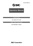
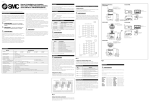
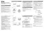
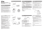
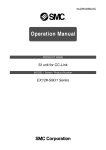
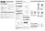
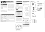
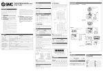
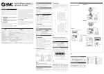
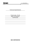
EX##-OMC0002-A
CompoBus/S SI unit
PRODUCT NAME
EX12※-SCS1/SCS2 Series
MODEL/ Series
CONTENTS
Forward..............................................................................................................................................3
1.Directions ........................................................................................................................................3
2.Characteristics and System Structure.............................................................................................4
2-1.Characteristics ......................................................................................................................4
2-2.System structure ...................................................................................................................5
3.Applicable PLC ...............................................................................................................................6
4.Specifications..................................................................................................................................7
4-1.SI unit specifications .............................................................................................................7
4-2. CompoBus/S systemspecifications......................................................................................8
4-3.External form of SI unit .........................................................................................................9
4-4.How to order SI unit ............................................................................................................11
5.Name and effect of each part of unit.............................................................................................12
5-1.LED Indication ....................................................................................................................12
5-2.Name of the terminal boad .................................................................................................12
6.Switch setting................................................................................................................................13
6-1.Address setting ...................................................................................................................13
6-2.Hold/Clear setting ...............................................................................................................15
7.Wiring............................................................................................................................................15
7-1.Wiring of communication line..............................................................................................15
7-2.Termination resistance .......................................................................................................17
7-3.Communication cable .........................................................................................................17
7-4.Wiring of power...................................................................................................................18
8.SI unit output no. and solenoid valve coil......................................................................................19
8-1.Standard wiring...................................................................................................................19
8-2.Made-to order wiring(mixed wiring) ...................................................................................20
9.Troubleshooting ............................................................................................................................21
-2-
Forward
● Indication and meaning of directions
Caution:
Operator error could result in injury or equipment damage.
Warning: Operator error could result in serious injury or loss of life.
(Note)
: Explanations of related matters
1.Directions
Warning
z
This product is intended to be used to the general FA equipment.
The use of this
product should be avoided for the equipment and device that human life may be directly
injured and malfunction or failure may cause enormous loss.
z
This product should no be disassembled and remodeled.
Caution
z
Read this operation manual thoroughly and use the product within the range of
specifications, observing the directions strictly.
z
Make sure if this product and all the equipment connected with this product are turned
off when wiring or inspecting.
z
Don't touch the terminal and internal circuit boards while they are energized.
z
Tighten wires securely with terminal screws.
-3-
2.Characteristics and System Structure
2-1.Characteristics
z
CompoBus / S system
Serial transmission system in which master and slave etc. are connected together by one
cable thanks to OMRON Corp. PLC
( programmable logic controller ) SYSMAC Series and CompoBus / S master unit.
z
SI manifold solenoid valve for CompoBus /S
Manifold solenoid valve with the remote Output unit (SI unit) connectable to
CompoBus /S system. The occupying output point of SI unit is 16 or 8 points.
z
Control many solenoid valves by one serial transmission cable
Since SMC's SI unit transmits directly from master unit, wiring manpower can be reduced.
z
High-speed communication cycle time
The max. of 32 slaves , 256 ( IN 128/OUT 128 ) IN/OUT put are connected in the
high-speed communication cycle time of 1 ms or less.
z
Highly free system is built by T branch style and multi-drop style.
Wiring can be composed freely by T branch style and multi-drop style.
The length of the trunk line can be extended to 100m maximun.
z
Greatly reduced maintenance
The signal wiring will become one serial transmission cable, which will decrease much of
the maintenance at the time of trouble like wrong, disconnection, etc. and increase
credibility.
-4-
2-2.System structure
CompoBus/S master unit
OMRON Corp. PLC
Special flat cable
T-branch
Multi drop
Communication
power
Supply power
for
solenoid valve
SI unit
SI unit
OMRON Corp.
Remote I/O terminal
Sensor terminal, etc.
SMC Corp.
SI manifold solenoid valve
-5-
Termination
resistance
3.Applicable PLC
This SI unit is connected to the CompoBus/S system of OMRON Corp.
CompoBus/S has the following applicable PLC and master unit.
Applicable PLC
C200HX/HG/HE, C200HS
CQM1
Applicable master unit
C200HW - SRM21
CQM1 - SRM21
Max. IN/OUT put point per
master
IN128/OUT128 point or
CQM1-CPU11/21:
IN32/OUT32 point or
IN16/OUT32 point
CQM1-CPU41/42/43/44:
IN64/OUT64 point or
IN32/OUT32 point or
IN16/OUT16 point
No. of the max. connection
SI unit per master
when using EX12∗-SCS1
(16 points output):
8 or 4 units
when using EX12∗-SCS2
(8 points output) :
16 or 8 units
IN64/OUT64 point
EX12∗-SCS1 (16 points output):
4, 2 or 1 unit
EX12∗-SCS2 (8 points output) :
8, 4 or 2 units
∗:
0, 1 or 2 or 4D or 4U
(Note)
Number of max. IN/OUT put points and max. connection SI unit are decided by setting the dip
switch for setting the no. of max. connection slave of master unit.
Please refer to OMRON Corp. CompoBus/ S user's manual, etc. for details about PLC and master
unit.
-6-
4.Specifications
4-1.SI unit specifications
Items
Types of SI unit
Specifications
EX120/121/122/
EX124U/D - SCS1
EX120/121/122/
EX124U/D - SCS2
Operating ambient temperature
0 to 55 oC
Operating ambient humidity
35 to 85% RH (without condensation )
Storage ambient temperature
- 20 to + 65oC
Vibration resistance
49 m/s2
Impact resistance
98 m/s2
Noise resistance
±1000 Vp - p pulse width 1µs , leading 1 ns pulse
Dielectric strength
between the full external terminal and case: 1500 VAC
for 1 minute
Insulating resistance
between the full external terminal and case: 500 VDC
2MΩ or more
Operating atmosphere
without corrosive gas nor dust
Occupied output point
16 points
8 points
Output style
transistor style (NPN open collector style )
Connection load
24 VDC, solenoid valve with lamp - surge voltage
protection circuit of 2.1 W or less, SMC product
Residual voltage
0.4 V or less
Communication power voltage
14 to 26.4 VDC
Supply power voltage for solenoid valve
24 VDC + 10%/-5%
Current consumption
Communication power 0.1 A or less 24 VDC
Weight
EX120: 110 g or less
EX121: 140 g or less
EX122: 130 g or less
EX124U/D: 240 g or less
-7-
4-2.CompoBus / S system specifications
Items
Applicable PLC
Communication style
Communication speed
Modulation style
Specifications
OMRON Corp. C200HX/HG/HE, C200HS, CQM1
Protocol for CompoBus/S
750 k bit/s
base band style
Symbol style
Manchester symbol style
Error control
Manchester symbol check, frame length check,
parity check
Connection style
Distance
T branch style, multi drop style
Type of cable
trunk line length
when using
VCTF cable
100 m or less
when using the
special flat cable
30 m or less
branch line length
full length of
branch line
3 m or less
50 m or less
3 m or less
30 m or less
But if the no. of slave connection is 16 or less even when using the special flat cable, the
length of trunk line can be 100 m or less and full length of branch line 50 m or less.
Max. IN/OUT put point
Type of master
Max. IN/OUT put points
when using the C200HW - SRM21
IN128/OUT128 point or
IN 64/OUT 64 point
when using the CQM1 - SRM21
IN 64/OUT 64 point or
IN 32/OUT 32 point or
IN 16/OUT 16 point
(Note)
Please refer to OMRON Corp. CompoBus/ S user's manual, etc. for details.
-8-
4-3.External form of SI unit
(1)External form of EX120 - SCS1 and 2
(2)External form of EX121 - SCS1 and 2
-9-
(3)External form of EX122 - SCS1 and 2
(4)External form of EX124D/U - SCS1 and 2
-10-
4-4.How to order SI unit
EX120−SCS1
Type of SI unit
Occupying output point
20
vertical type, VQ direct mounting
1
16 points
21
vertical type, DIN rail mounting
2
8 points
22
vertical type, SY/SX direct mounting
24U/D VQ2000, VQ4000
Applicable PLC maker
CS
OMRON Corp.
CompoBus / S
-11-
5.Name and effect of each part of unit
5-1.LED Indication
EX120-SCS*
EX121-SCS*
EX124U-SCS*
EX122-SCS*
EX124D-SCS*
LED
Contents
PWR
Light is on or off as the power supply for
communication is on or off respectively.
COMM
Light is on during normal communication and off in
error or stand-by mode.
ERR
Light is on when communication error occurs and
off in normal condition stand-by mode.
5-2.Name of the terminal board
Terminal
dip switch for setting
1
ADDRESS No.
PWR COMM ERR
0
BS+ BSH BSL BS-
FG
24V
0V
Where to connect
BS+
BS+ communication power line
BDH
BDH communication line
BDL
BDL communication line
BS -
BS- communication power line
FG
Functional Ground
24V
24 V for solenoid valves power
0V
0 V for solenoid valves power
Terminal thread is M3 thread.
terminal board
-12-
6.Switch Setting
The switch of SI unit should be set while the power is off.
6-1.Address setting
(1)ADDRESS NO. (node address)
The node address setting range depends on the type or setting of the master as follows:•For master unit C200HX/HG/HE, C200HS
If max. number of connected slaves is 16 (IN8/OUT8), the node address
setting range is 0 to 7.
If max. number of connected slaves is 32 (IN16/OUT16), the node address
setting range is 0 to 15
•For master unit CQM1:
The number of channels occupied by the PLC or master unit and the number of points
occupied by one node address, are related as follows:
Number of CH
occupied by PLC
Number of points
occupied by one node address
IN1/OUT1
8
IN :0 to 1
OUT:0 to 1
IN2
OUT2
IN2/OUT2
8
IN :0 to 3
OUT:0 to 3
IN4
OUT4
IN4/OUT4
8
IN :0 to 7
OUT:0 to 7
IN8
OUT8
IN1/OUT1
4
IN :0 to 3
OUT:0 to 3
IN4
OUT4
IN2/OUT2
4
IN :0 to 7
OUT:0 to 7
IN8
OUT8
IN4/OUT4
4
IN :0 to 15
OUT:0 to 15
IN16
OUT16
Setting range
-13-
Max. number of
connected slaves
(Note)
•The duplication of a node address in different slaves will cause communication error.
•For 16 point slaves which are assigned to one channel. although it occupies 2 slaves with 8 points,
the node address which is not used must be as follow:If the node address used is odd: Node address with no. just before must also be used.
If the node address used is even: Node address with no. just after must also be used.
For example, if the node address 5 is set to a 16 points SI unit(a kind of slave), the node address
4 must also be used for the SI unit.
•For master unit CQM1, if 8 points slave is connected in 4 points mode.
The slave is considered to occupy points for 2 slaves, and the node address just after the set
node address to the slave must also be used.
If the node address is duplicated with another slave,
communication error occurs and makes it impossible to start
communication with CompoBus/S.
• During 4 points mode, 16 points slave is not available.
(2)Switch setting
Open the terminal board cover on the upper section of SI unit and set the DIP switch.
1
ON
0
1
2
4
3
5
6
OFF
node address
Hold / Clear
•Setting of node address
Set the node address with SW 1 to 4 as follows:
node address
SW1
SW2
SW3
SW4
node address
0:
SW1
OFF, 1:
SW2
ON
SW3
SW4
0
0
0
0
0
8
0
0
0
1
1
1
0
0
0
9
1
0
0
1
2
0
1
0
0
10
0
1
0
1
3
1
1
0
0
11
1
1
0
1
4
0
0
1
0
12
0
0
1
1
5
1
0
1
0
13
1
0
1
1
6
0
1
1
0
14
0
1
1
1
7
1
1
1
0
15
1
1
1
1
-14-
6-2.Hold/Clear setting
This setting is intended to determine whether output of SI unit should be held or cleared totally
when communication error occurs.
In SW5, setting is available as follows. 0: OFF 1: ON
Hold/Clear setting
SW5
Clear
0
Hold
1
(Note)
Switch SW6 must remain off in use.
7.Wiring
7-1.Wiring of communication line
Connecting style of the CompoBus/S slave has 2 types:
T branch style and multi-drop style.
In the T branch style, slave is connected with branch line that branched off from the trunk line.
In the multi-drop style, slave is connected directly with the trunk line.
be branched off from the branch line.
But branch line cannot
When branch line is branched off from the trunk line,
special pressure welding connector for branch or terminal board is used.
When communication
able is connected with SI unit, BDH and BDL communication lines are connected with BDH and
BDL terminals respectively. Communication power BS+ and BS- lines are also connected to BS+
and BS- terminals respectively.
Pressure welding connector for branch
Master unit
Termination
resistance
BDH
BDL
Special flat cable
Insulation treatment
Stabilized
power
BS+ BDH BDL BS- FG 24V 0V
BS+ BDH BDL BS- FG 24V 0V
SI unit
SI unit
Ground
stabilized
power
-15-
Ground
Stabilized
power
This SI unit is multi power supply type slave.It has 2 supplying sections for communication and
solenoid valve.It's possible to supply power to the supplying section for communication by the
special flat cable.But another power is needed at the supplying section for solenoid valve.Also,
the power can be supplied from the supply power for solenoid valve to communication power
supplying section.
The communication line of special flat cable is as follows:
communication power + side (BS+), brown
communication line High side (BDH), black
communication line Low side (BDL), white
communication power - side (BS-), blue
Caution
The communication cable should be wired away from the power cable and high voltage cable in
order not to be affected by noise, etc.
Cable should be connected without mistake.
If it is wired wrongly, SI unit and other devices may
be damaged.
-16-
7-2.Termination resistance
The termination resistance should be mounted at the end of trunk line on the opposite side of the
master in order to stabilize the communication.
The following OMRON Corp. 's products should
be used for the termination resistance.
z
SRS1-T
terminal with the termination resistance usable for VCTF and special flat cable
z
SCN1-TH4T
pressure welding connector with the termination resistance
usable only for the special cable
When the communication cable is connected to the terminal base with termination resistance,
it is necessary to connect both BDH and BDL to an appropriate terminal.
If the network is connected in T branch style, it is necessary to connect a termination resistance to
the end of the longest branch cable, so that the termination resistance is positioned at the furthest
point from the master.
7-3.Communication cable
Type
VCTF Cable
Compobus flat cable
SCA1-4F10 (length 100m)
Specifications
Vinyl cable VCTF JIS C 3306
2-cores, Nominal section 0.75 mm2
(Signal line×2)
Conductor resistance (at 20℃): 25.1Ω/km
Nominal section 0.75 mm2 ×4
(Signal line×2, Power line×2)
Ambient temp.: 60℃ or less.
-17-
7-4.Wiring of power
This SI unit is multi-power supply type slave.
There are 2 supplying sections: for
communication and for solenoid valve.
(1)Power supply for communication
• If VCTF cable is used for the communication, the power must be supplied for the SI unit
by a separate cable.
• If Compobus flat cable is used for the communication, the power is supplied for the
SI unit by the flat cable.
(2)Power supply for solenoid valve
• Power supply 24 VDC, +10% -5% is required.
• The power supply and cables used should be selected with consideration to the current
consumption of the solenoid valves and of the SI unit.
( Note)
The separate power supply should have margin in its capacity enough for in-rush current at
start up.
Caution
When using the Compobus flat cable for communication, any unused power supply cables
must be isolated at both ends.
-18-
8.SI unit output no. and solenoid valve coil
8-1.Standard wiring
The output of SI unit is allotted in order from the D-side solenoid valve.
In the case of VQ
manifold solenoid valve, SI unit will be attached at the D-side, and so output will be 0, 1, 2 …
from the side of SI unit.
In the case of SX, SY manifold solenoid valve, the mounting direction
of SI unit is on the side of D and U.
Therefore, if SI unit is mounted on the U-side, the output
number will be allotted in order from the solenoid valve on the opposite side of SI unit.
When the number of station of VQ, SX manifold solenoid valve is 8 or less, the wiring inside the
manifold will all be double wiring.
SY manifold solenoid valve will be all single wiring.
[ e.g. of wiring 1: VQ manifold solenoid valve ] [ e.g. of wiring 2: SX manifold solenoid valve (U-side)]
U
9
・
7
・
5
・
3
・
1
・
・・ B
A
・・ evacuated
A
・・
double
5
single
4
single
3
double
2
double
1
U
SI unit
output no.
9
・
7
・
5
・
3
・
1
・
evacuated
A
・・ B
A
・・ B
A
SI unit
output no.
SI unit
stations
D
・・ B
A
・・ evacuated
A
・・
SI unit
double
5
single
4
single
3
double
2
double
1
evacuated
A
・・ B
A
・・ B
A
In the e.g. of wiring shown above, the 3rd ,4th single can be changed to double.
rd
stations
D
In this case,
the output no. of the 3 solenoid valve on the B side will be 5, the output no. of 4th solenoid valve
on the B side will be 7.
-19-
8-2.Made-to order wiring ( mixed wiring )
The mixed wiring can be done as the made-to-order wiring.
Specify the wiring specifications
by the manifold specifications, when the solenoid valve stations are 9~16 or when continuous
output will be allotted to the single solenoid valve with VQ, SX manifold solenoid valve stations
of 8 or less.
[ e.g. of wiring:
VQ manifold solenoid valve ]
It is fixed depending on whether the solenoid valve
carrying the manifold inside wiring is single or
double.
U
In this case, please note that it's impossible to output
15 ・・ A
single
15
since the inside wiring is not done to the B side of
14 ・・ A
single
14
solenoid even if the solenoid valve is changed from
single to double. The max. station of the single
2 ・・ A
single
2
1 ・・ B
・
A
double
1
SI unit
output no.
SI unit
solenoid valve is 8 and 16 respectively when SI unit
output point is 8 and 16.
(Reference)
stations
D
For mixed wiring, the wiring specifications should be
written clearly in the manifold specifications.
-20-
9.Troubleshooting
The following flow chart shows directions to solve the malfunction when SI unit doesn't operate
normally.
Refer to OMRON Corp. CompoBus/S user manual, etc. for the entire trouble
shooting.
The solenoid valve
doesn't operate.
Is the
LED of solenoid valve
lighting up?
YES
Please contact SMC.
NO
YES
Is PWR LED
lighting up?
Is the
communication
power supplied?
NO
NO
Supply the
communication power.
NO
Set the node
address correctly.
NO
Supply the supply
power (DC24V) for
solenoid valve.
YES
Is COMM LED
lighting up?
YES
Is the node address
set correctly?
NO
Check the ERR LED indication,
setting of PLC and program,
wiring, etc.
Refer to the OMRON, Corp.
User's Manual, etc. for details.
If the communication trouble
isn't solved nevertheless,
please contact SMC.
YES
YES
Is the
supply power for
solenoid valve
(DC24V) supplied?
-21-