1
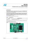
®
RINGDALE
1569 Energy Monitor
and
Energy Analyzer Application
Quick Integration Guide
Ethernet Version
Revision: 1.09
Date: May 20, 2015
Page 1 of 42
1569 Energy Monitor and Energy Analyzer Application User Manual
Copyright, Disclaimer and Trademarks
Copyright
Copyright 1997-2008 © Ringdale, Inc. All rights reserved. No part of this publication may be
reproduced, transmitted, transcribed, stored in a retrieval system, or translated into any language or any
computer language, in any form or by any third party, without prior permission of Ringdale UK Limited.
Disclaimer
Ringdale, Inc. reserves the right to revise this publication and to make changes from time to time to the
contents hereof without obligation to notify any person or organisation of such revision or changes.
Ringdale, Inc has endeavoured to ensure that the information in this publication is correct, but will not
accept liability for any error or omission.
NOTE:
Because of the fast pace of software development it is possible that there will be minor differences
between the manual and the actual release of the program.
Trademarks
All trademarks are hereby acknowledged.
Page 2 of 42
1569 Energy Monitor and Energy Analyzer Application User Manual
Table of Contents
Copyright, Disclaimer and Trademarks ..................................................................................................... 2
Table of Contents Introduction .................................................................................................................. 3
Introduction ................................................................................................................................................ 4
Energy Monitor Hardware ..................................................................................................................... 4
Energy Analyzer Application ................................................................................................................. 5
Configure ............................................................................................................................... 5
Program ............................................................................................................................................ 5
Monitor ................................................................................................................................... 5
Connecting an Energy Monitor.................................................................................................................. 6
Programming Location .......................................................................................................................... 6
Once programmed and ready to install ................................................................................................ 6
Configuring an Energy Monitor ................................................................................................................. 8
General ................................................................................................................................ 10
TCP/IP ............................................................................................................................................ 11
E-mail Settings ............................................................................................................................... 13
Time and Date ................................................................................................................................ 15
CT Select .....................................................................................................................................................16
Debug ............................................................................................................................................. 17
Controlling the Energy Monitor ........................................................................................................... 18
Listen to Device ..........................................................................................................................................18
Manual Control ..................................................................................................................... 19
Records Panel ............................................................................................................................................20
Incoming Records .......................................................................................................................... 20
Save Records..............................................................................................................................................20
Log Records ................................................................................................................................................21
Programming an Energy Monitor ............................................................................................................ 22
Program Device .................................................................................................................................. 23
Sample Frequency ......................................................................................................................................23
Start and Stop Times ..................................................................................................................................24
Monitor Mode ....................................................................................................................... 25
Alarms ............................................................................................................................................ 26
Setting up an Energy Monitor – Using a Web Browser .......................................................................... 27
Configuration ............................................................................................................................ 28
Configuration - General Settings ................................................................................................... 28
Configuration – Password .............................................................................................................. 28
Configuration – TCP/IP .................................................................................................................. 29
Configuration – E-Mail Settings ..................................................................................................... 30
Configuration – Time and Date ...................................................................................................... 31
Configuration – CT Select .............................................................................................................. 32
Configuration – Reset to Defaults .................................................................................................. 32
Programming....................................................................................................................................... 33
Monitor Control ......................................................................................................................... 34
Start or Stop Monitor Now.............................................................................................................. 34
Status .................................................................................................................................................. 34
Contents .............................................................................................................................................. 35
About ................................................................................................................................................... 36
Collecting Monitor Records ..................................................................................................................... 37
Output files............................................................................................................................................... 38
Technical Specifications .......................................................................................................................................39
Records Definitions ............................................................................................................................. 39
Glossary ................................................................................................................................................... 41
Technical Support Contact Information................................................................................................... 42
Page 3 of 42
1569 Energy Monitor and Energy Analyzer Application User Manual
Introduction
The Energy Monitor is a 3-phase current transformer data logger with either an Ethernet or a USB
interface. The Energy Monitor may be programmed to monitor various different aspects of electrical
power. An application is required to set up the Energy Monitor and to analyse the various types of
readings it will produce.
The application has multiple modes of operation. It is first used to set up the Energy Monitor so that it
may collect data. Later it is used to retrieve and analyse that data. It may also analyse data as it arrives
in real time.
The part number for the Ethernet version of the product is 00-11-0569-0000. For the USB Version, see
part number 00-11-0569-0001.
Energy Monitor Hardware
The Energy Monitor is available with either an Ethernet or a USB interface.
Ethernet Connected
The device is connected to a LAN and may be powered by either PoE or a 12V supply. In this mode the
unit may send emails or other alerts when programmed conditions are encountered or in response to a
programmed schedule. Data may be transmitted on the LAN and also stored on an external flash drive.
The User interface will be through either the Energy Analyzer application or with a web browser.
USB Flash Drive
Data may be transmitted to the computer for storage and/or stored on an external flash drive.
The Energy Monitor offers a USB port for connection of a Flash Drive. Data samples will be written to a
compatible Flash Drive as they are obtained and may be viewed and analysed later. The Flash Drive
may be removed (when safe to do so) and plugged directly into a PC for data analysis using the
EnergyAnalyzer application.
The Flash Drive must use the ‘USB Mass Storage Class’ with a sub-class of ‘SCSI transparent’ and the
transport protocol ‘Bulk-Only Transport’.
Examples of Flash Drives that use these standards are:
Ringdale USB 2.0 1GB
Pretec I-Disk
SanDisk 1GB Cruzer Micro
Toshiba 2GB
Verbatim 8GB (formatted for 2GB)
The Flash Drive must be formatted as FAT or FAT16.
The Energy Monitor expects a file named “DATALOG.BIN” in the root directory and the data area of
that file to be contiguous. Once created, the same file will be re-used. Do not move or copy the file on
the drive as this may result in fragmentation and the possible corruption of the disk storage structures.
The file size determines the maximum number of samples that may be stored within it. At the maximum
file size of 512MB, approximately 16.7 million data sample records may be stored, 19.4 days when
sampling at a 1/10 second frequency.
Page 4 of 42
1569 Energy Monitor and Energy Analyzer Application User Manual
Energy Analyzer Application
The Energy Analyzer Application is used to configure, program and monitor one or more devices.
Configure
The term “configure” means setting up the Energy Monitor’s name, TCP/IP, E-mail, and Time & Date
parameters.
Program
This refers to instructing the Energy Monitor when to start sampling and how often.
Monitor
This function is used to 1) set the application to listen to the device, 2) set it to collect records and
determine where the record file is kept, and 3) whether to save records and/or logs.
Records are binary data.
Log Records are interpreted records that are readable text.
Page 5 of 42
1569 Energy Monitor and Energy Analyzer Application User Manual
Connecting an Energy Monitor
Types of Service Supported
Supported electric services include 50 or 60-hertz, alternating current, single-phase or three-phase.
Nominal secondary voltages are listed below:
Type
Volt(nominal)
Single-phase,
Single-phase,
100 to 240-Volt, two-wire, grounded
120/240-Volt,
three-wire, grounded
Three-phase,
Three-phase,
208Y/120-Volt, four-wire, grounded, wye 10
385Y/220-Volt, four-wire, grounded, wye 10
Three-phase,
Three-phase,
420Y/230-Volt, four-wire, grounded, wye 10
480Y/277-Volt, four-wire, Delta
11
US 3 phase
mainly Germany high power users,
In Germany also used as Household Power.
mainly UK, Canada, Australia high power users
mainly US
Three-phase,
208 to 480-Volt, three wire, Delta
US, Europe, Japan high power user
Page 6 of 42
1569 Energy Monitor and Energy Analyzer Application User Manual
Conductors
Mode
Description
00
00
Mainly Japan and US small user power
mainly US Household power
01
Programming Location
For convenience, an Energy Monitor should be configured before locating it at the place where it will be
coupled to the power lines. Although this is not mandatory, there may not be easy access to the
network.
For the purpose of programming, connect the device to the network in any convenient location.
Connect the power supply into the wall socket and the Energy Monitor.
Once programmed and ready to install
1) Plug in the USB Flash Drive if you have it.
2) If Ethernet is available, plug the Ethernet cable into the RJ45 jack.
Note: Power over Ethernet (PoE) cables are limited to a maximum of 36 feet.
When not using PoE:
You can connect up to a maximum of 100 Meters (328 feet, 109 yards) for 100baseT
or 500 meters (1500 feet) for 10baseT.
Page 7 of 42
1569 Energy Monitor and Energy Analyzer Application User Manual
IMPORTANT NOTE: The user should exercise caution in connecting the voltage and current inputs
since the connection points may be live. It would be best to disconnect power when connecting but that
may not be practical in all cases. Inspect the voltage and current sensing cables for damaged insulation
and exposed conductors before each use and do not use if damage is found. Replacement voltage
cables and current transformers may be purchased from Ringdale and current transformers with
damaged cables may be returned for repair.
3) There is only one way to connect the voltage and current sensing cables to the Energy Monitor:
./
./
./
./
The current transformers clip around current-carrying conductors and connect to the
Energy Analyzer at the AØ, BØ, and CØ Current inputs.
The red and green connectors are used to measure voltage.
The green connects to the neutral (grounded) conductor.
The red wires connect to each of the 3 voltage phases. The red wire adjacent to the
green wire is for the AØ. The next red wire is the BØ. The last red wire is the CØ.
4) Unless using PoE, connect the power supply into the wall socket and the Energy Monitor.
Page 8 of 42
1569 Energy Monitor and Energy Analyzer Application User Manual
Configuring an Energy Monitor
Network configuration of an Energy Monitor device may be done using the Energy Analyzer Application
or a web browser. Basic setup includes setting the device IP address, specifying the e-mail server
address and destination e-mail recipients for alert messages.
For configuration using a web browser, please go to page 14. To use the application, please read on.
Start the Energy Analyzer Application.
A device must first be selected. Click “Select Device”.
Any Energy Monitors on your network will show up in the panel as shown above. If it doesn’t appear
straight away, use the Requery Network button to try again to find the device. Click on the device that is
to be configured to highlight it and then click the OK button.
If you have a USB version of the Energy Monitor, select that tab to see it.
Use the Select a File for a previously saved file.
Page 9 of 42
1569 Energy Monitor and Energy Analyzer Application User Manual
IMPORTANT NOTE:
All Energy Monitors are shipped with a factory default IP address of 11.22.33.44. To avoid
TCP/IP conflicts, only one device that has not been configured should be connected to the network at a
time.
Once selected, the device’s name will appear in the main panel and the three options “Connect
Selected Device”, “Configure Selected Device”, and “Program Selected Device” will become available.
The first step is to configure the Energy Monitor’s name, TCP/IP, E-mail, and Time & Date parameters.
Click on the
up.
Configure Selected Device
Page 10 of
1569 Energy Monitor and Energy Analyzer Application User Manual
button and the Configure Network Device panel will come
General
The General tab allows you to modify the device name and set or change a password.
It also shows the Hardware model and Firmware revision.
Page 10 of 42
1569 Energy Monitor and Energy Analyzer Application User Manual
TCP/IP
This tab is used to assign the Energy Monitor with an appropriate IP address for your network. It also
allows you to set the IP addresses that the Energy Monitor will contact for e-mail sending and accurate
time keeping. When changing the IP address of the Energy Monitor, it is best to make just that change
first, then go back to “Select Device” to re-select the device using its new IP address, and then make the
other changes.
1) Enter an unused IP Address from your network, or click on the DHCP/RARP Enable.
NOTE: If you change to an address that is NOT in the same network range that your PC is, you will
still be able to see the Energy Monitor with the Energy Monitor utility, but you will not be able to
change any parameters until you are on the same subnet.
2) If you are not using DHCP or RARP, enter the Subnet Mask.
3) If you are not using DHCP or RARP, set the Default Gateway.
4) DNS Servers, 1 and 2, are the Domain Name Servers provided by your ISP. It is used to
convert the Mail Server SMTP Address’s URL to an IP Address.
Page 11 of 42
1569 Energy Monitor and Energy Analyzer Application User Manual
5) If you have a DNS server defined, the Mail Server SMTP Address can be entered either as a
URL (for example smtp-server.austin.rr.com) or an IP Address. Using the URL is recommended if
you may be changing your network, and you have your own mail server.
6) Time Server IP 1,2, & 3. You can either set the time manually on the Time and Date panel or
configure up to three preferred timeservers. Without the correct time, the timestamp will be
incorrect on all records, and if you email Alert conditions, your spam filter may trap the email.
The 192.043.244.018 address is the timeserver at NCAR.
TIME SERVER NOTE: All timeservers send the time UTC. In order to set the time stamps correctly you
must adjust your Time Zone Offset under the Time and Date tab. There is a list of public timeservers at
this URL: http://tf.nist.gov/service/time-servers.html
Page 12 of 42
1569 Energy Monitor and Energy Analyzer Application User Manual
E- mail Settings
The e-mail settings are used to send an Alert message if certain triggers are met.
1) Mail Server SMTP Address – Use the TCP/IP tab to change this.
2) Mailserver SMTP IP Port – The default is 25. This is most common. Other common ports used
are 26, and 2525.
3) Mailserver Login Name – Often this is an email address. When a fax is received in the email
box, it will come from this user. Max 58 characters.
4) Mailserver Login Password – This is the password for the above email account. There is a
maximum of 58 characters. NOTE: case-sensitive.
5) Reply e-mail Address – If the person who receives the fax does a reply, it will go to this address.
6) Reply Name – This is the name that shows in the email header when you receive a fax.
7) Destination e-mail Address(es) - This is where the email will be sent. This can be the same as
item 2) or it may be an alias set up to forward to multiple users. Simply enter the addresses
you wish to send to as one entry, each address separated by either a semi-colon (;) or a
Page 13 of 42
1569 Energy Monitor and Energy Analyzer Application User Manual
comma (,). There is a limitation of a maximum of 80 characters for all addresses. No
spaces are allowed. Enter each address on a new line.
Page 14 of 42
1569 Energy Monitor and Energy Analyzer Application User Manual
Time and Date
The Energy Monitor features a battery backed up clock. When first set up and periodically after, the
clock may be (re) synchronized with a time server or the PC running the Energy Analyzer application.
If at least one Time Server IP address has been specified, the Energy Monitor will automatically contact
a Time Server to keep its clock accurate. Note that it will not adjust its clock while it is monitoring to
avoid spoiling the record sequence.
The “Set Device Time From PC Clock” function allows you to synchronize the device time with the PC
time. This option is only available if no Time Servers have been specified.
TIME SERVER NOTE: Some local timeservers and all Internet timeservers send the time in UTC. In order
to set the time stamps correctly you may need to adjust your Time Zone Offset and select or de-select
the Daylight Savings Enable option.
Page 15 of 42
1569 Energy Monitor and Energy Analyzer Application User Manual
CT Select
Select the value of the current transformers that you are using.
Page 16 of 42
1569 Energy Monitor and Energy Analyzer Application User Manual
Debug
The Energy Monitor keeps a log of various messages. This panel is useful only if a problem should
arise, at which time obtaining the recent messages may prove informative. Under normal circumstances
there is no need to use this panel.
Page 17 of 42
1569 Energy Monitor and Energy Analyzer Application User Manual
Controlling the Energy Monitor
Select the device to monitor and connect to it using the
Connect Selected Device
button.
When successfully connected the Actions buttons will become available.
Listen to Device
This will tell the Energy Monitor to send a copy of each sample record to you. If the device is not
actually running, then you will not receive any records. Sample records will still be recorded into a flash
drive if fitted, regardless of this setting.
Page 18 of 42
1569 Energy Monitor and Energy Analyzer Application User Manual
Manual Control
This window only stays up for 30 seconds. The eight buttons give you the choice of action you want the
device to take.
Start and Stop Sampling are normally used to begin and end a sampling session if there is no automatic
start and stop Time and / or Date defined.
When the Energy Monitor is running, the Stop Sampling button must be used before removing a flash
drive to ensure that the sample record file is closed properly, and to ensure that the flash drive can safely
be removed.
Pause and Resume are used where sampling is temporarily stopped.
IMPORTANT NOTE: The flash drive should not be removed while the device is running or paused.
Removal of the flash drive without stopping the unit may result lost data of up to 16 of the last records
sampled.
Device Status
This button will show you the status of the Energy Monitor but is currently not implemented.
Use the web interface to get status of the sampling and the levels of each channel.
Page 19 of 42
1569 Energy Monitor and Energy Analyzer Application User Manual
Records Panel
Incoming Records
The device must be in Listen mode by selecting the Listen to Device button. You must also set the
device to sample records either manually or using the Program Start/Stop Times.
Save Records
Put a check in the Save Records box to bring up the location where the records binary file will be kept. If
you select the same name as a previously saved bin file, it will be overwritten.
The device must be in Listen mode by selecting the Listen to Device button. You must also set the
device to sample records either manually or using the Program Start/Stop Times.
Page 20 of 42
1569 Energy Monitor and Energy Analyzer Application User Manual
Log Records
Put a check in the Log Records box to bring up the location where the records binary file will be kept. If
you select the same name as a previously saved bin file, it will append to the previous data.
The device must be in Listen mode by selecting the Listen to Device button. You must also set the
device to sample records either manually or using the Program Start/Stop Times.
About
Click on the
About
button to find the version of the EnergyAnalzer software.
Page 21 of 42
1569 Energy Monitor and Energy Analyzer Application User Manual
Programming an Energy Monitor
Sample records will be recorded into a flash drive (if one is plugged in) as soon as either the Manual
Control / Start Sampling has been selected or it is between the Start Time and Stop Time.
Click on the Program Selected Device button to call up the Program Device panel.
Page 22 of 42
1569 Energy Monitor and Energy Analyzer Application User Manual
Program Device
Sample Frequency
The sample frequency determines how often a sample is reported. At 18000, one sample is taken every
30 minutes. At 10, one sample is taken per second. At 1, ten samples are taken per second.
Page 23 of 42
1569 Energy Monitor and Energy Analyzer Application User Manual
Start and Stop Times
Each of the Start and Stop Times, Start Date and Stop Date may be given a value or left undefined.
Leave all of these values undefined if you intend to start and stop the device manually.
Specifying Start and Stop times but leaving the Dates undefined will set a repetition pattern. It is possible
to define the Start Time as 9:00 pm and the Stop Time as 6:00 am for monitoring through each night if
the dates are left undefined, or for a particular night or nights if the dates are defined.
Specifying a Start Date without specifying a Start Time, and the same for the Stop values, will have no
effect.
NOTE:
If Start and Stop times defined, you will not always be able to start and stop the device manually. For
example, if the device is programmed to start at 4:00 pm and stop at 10:00 pm, the device will
automatically restart if manually stopped between 4:00 pm and 10:00 pm. Similarly, manually starting
the device after 10:00 pm will result in an automatic stop. As a rule, it is better to not define Start and
Stop times if you wish to manually start and stop the unit, or to re-program with undefined times prior to
manually starting or stopping.
Page 24 of 42
1569 Energy Monitor and Energy Analyzer Application User Manual
Monitor Mode
The initial option is RMS Voltage and Current with Accumulated Watt Hours. Other Monitor Mode
options may be available by requesting through Technical Support. Email [email protected].
Page 25 of 42
1569 Energy Monitor and Energy Analyzer Application User Manual
Alarms
You can set an Alert to be sent to the Destination Email Address when monitoring starts and/or stops.
Future revisions will current/voltage threshold triggers.
Page 26 of 42
1569 Energy Monitor and Energy Analyzer Application User Manual
Setting up an Energy Monitor – Using a Web Browser
Open the Home page of the device. In our example here the device has an IP address of 205.242.238.124.
Note: You need to be on the same virtual network (subnet) as the device in order to be able to
communicate with it.
The upper panel shows the device description and the name currently assigned to the device –
“Energy Monitor” in our example.
Page 27 of 42
1569 Energy Monitor and Energy Analyzer Application User Manual
Configuration
Configuration is used for setting up the Energy Monitor’s name, TCP/IP, E-mail, and Time & Date
parameters. It also will allow you to change the password, download firmware, and reset to defaults.
Configuration - General Settings
This section allows you configure a unique name for each Energy Analyzer that you have.
Page 28 of 42
1569 Energy Monitor and Energy Analyzer Application User Manual
Configuration – Password
Page 29 of 42
1569 Energy Monitor and Energy Analyzer Application User Manual
Configuration – TCP/IP
IP Address – Enter an unused IP Address from your network, or click on the DHCP/RARP Enable.
NOTE: If you change to an address that is NOT in the same network range that your PC is, you will
still be able to see the Energy Monitor with the Energy Monitor utility, but you will not be able to
change any parameters until you are on the same subnet.
Subnet Mask – Enter the subnet mask.
DHCP can be used if you do not use static IP addresses on the network.
Gateway IP is the default gateway.
DNS Server 1,2 – DNS Servers can be used to resolve the Mail Server IP from the URL.
Mail Server IP/URL - If you will be configuring the Energy Monitor to report threshold trigger events, you
must enter an IP Address for the SMTP mail server.
Page 30 of 42
1569 Energy Monitor and Energy Analyzer Application User Manual
Configuration – E-Mail Settings
Mail Server SMTP Address – Use the TCP/IP tab to change this.
Mail Server SMTP IP Port – The default is 25. This is most common. Other common ports used are
26, and 2525.
Mail Server Login Name – Often this is an email address. When a fax is received in the email box,
it will come from this user. Max 58 characters.
Mail Server Login Password – This is the password for the above email account. There is a
maximum of 58 characters. NOTE: case-sensitive.
Reply e-mail Address – If the person who receives the fax does a reply, it will go to this address.
Reply Name – This is the name that shows in the email header when you receive a fax.
Destination e-mail Address(es) - This is where the email will be sent. This can be the same as the
Mail Server Login Name or it may be an alias set up to forward to multiple users. Simply enter the
addresses you wish to send to as one entry, each address separated by either a semi-colon (;) or a
comma (,). There is a limitation of a maximum of 80 characters for all addresses. Max 80
characters. No spaces are allowed. Enter each address on a new line.
Page 30 of 42
1569 Energy Monitor and Energy Analyzer Application User Manual
Configuration – Time and Date
The Time and Date option brings up the Clock Setting options and the current time. You can either
select time servers, or set the time and date manually. If the time is not set correctly the timestamp will
be incorrect and your spam filter may trap the email.
Time Server IP 1,2, & 3 – You can either set the time manually or use time servers. You can add up to
three time servers.
TIME SERVER NOTE: There is a list of public time servers at this URL: http://tf.nist.gov/service/timeservers.html
Time Zone Offset – All time servers send the time UT. In order to set the time stamps correctly you must
adjust your Time Zone Offset. This is the offset from UT. If you are in Greenwich, England, this number
will be 0. If your time zone is east of Greenwich, England), the number is positive. If your time zone is
west of GMT, the number is negative. For EST, use –5, CST –6, MST –7, PST –8, AKST –9, and HAST –
10.
Page 31 of 42
1569 Energy Monitor and Energy Analyzer Application User Manual
Configuration – CT Select
The CT Select option brings up the CT Selection menu where you can select either 150 Amp or 30 Amp
Current Transformers.
Configuration – Reset to Defaults
This will normally only be used under the direction of Technical Support. It will not change the IP
Address of the Energy Monitor.
Page 32 of 42
1569 Energy Monitor and Energy Analyzer Application User Manual
Programming
The Programming option brings up the following Programming page.
Sample Frequency
The sample frequency determines how often a sample is reported. At 18000, one sample is taken every
30 minutes. At 10, one sample is taken per second. At 1, ten samples are taken per second. The default
value is 20, the equivalent to a 2 second sample rate.
Start / Stop Times
Each of the Start and Stop Times, Start Date and Stop Date may be given a value or left undefined.
Leave all of these values undefined if you intend to start and stop the device manually.
Specifying Start and Stop times but leaving the Dates undefined will set a repetition pattern. It is possible
to define the Start Time as 9:00 pm and the Stop Time as 6:00 am for monitoring through each night if
the dates are left undefined, or for a particular night or nights if the dates are defined.
Page 33 of 42
1569 Energy Monitor and Energy Analyzer Application User Manual
Specifying a Start Date without specifying a Start Time, and the same for the Stop values, will have no
effect.
NOTE:
If Start and Stop times defined, you will not always be able to start and stop the device manually. For
example, if the device is programmed to start at 4:00 pm and stop at 10:00 pm, the device will
automatically restart if manually stopped between 4:00 pm and 10:00 pm. Similarly, manually starting
the device after 10:00 pm will result in an automatic stop. As a rule, it is better to not define Start and
Stop times if you wish to manually start and stop the unit, or to re-program with undefined times prior to
manually starting or stopping.
Monitor Mode
There are two fundamental monitor modes the first being the smallest record size recording only the basic
information of voltage, current and watt hours occupying 32 bytes per record and thus allowing to store the
maximum amount of records on the USB Flash drive. The extended mode records in addition reactive power
and VA.
Page 34 of 42
1569 Energy Monitor and Energy Analyzer Application User Manual
Alarms
Page 35 of 42
1569 Energy Monitor and Energy Analyzer Application User Manual
Control
The Control Panel provides access to Waveform and Montor Control Functions.
The Monitor Control option brings up the following Monitor Control page.
Start or Stop Monitor Now
Start and Stop are normally used to begin and end a sampling session.
Pause and Resume are used where sampling is temporarily stopped.
IMPORTANT NOTE: The flash drive should not be removed while the device is running or paused.
Removal of the flash drive without stopping the unit may result in corrupted data.
Page 36 of 42
1569 Energy Monitor and Energy Analyzer Application User Manual
Status
Click the Status option to verify if the unit is running or not.
Page 37 of 42
1569 Energy Monitor and Energy Analyzer Application User Manual
Contents
Clicking on Contents brings up an Index page. The functions on this page are the same as those on the
Home page.
Page 38 of 42
1569 Energy Monitor and Energy Analyzer Application User Manual
About
This page provides information about the unit.
Page 39 of 42
1569 Energy Monitor and Energy Analyzer Application User Manual
Collecting Monitor Records
Data Records may be obtained from one of three sources, 1) from a Network device, 2) from a USB
device and 3) from a folder that includes the file from the USB flash drive that has been written by the
device.
Records should be considered to come in a stream.
The Energy Monitor may be started and stopped manually using the Manual Control panel, or it can be
programmed to start and/or stop automatically at certain times and dates.
You can take the compact flash; plug it into a PC with the EnergyAnalyzer for analysis. This is the
procedure:
1) Take the compact flash, plug it into a PC.
2) Open the EnergyAnalyzer application. Click the Select Device
button, then the Select A File tab
3) Click the Browse button and choose the datalog.bin
4) Click Connect Selected Device.
5) Put a check in Log Records. Provide a file name for the text file.
6) Click Listen to Device to see the data go by.
The text file is space delimited.
When it is done you can import the file into Excel and generate a chart.
USB Flash Device
The only USB Flash devices supported are up to 2GB with FAT format 2048 bytes per sector.
The filename is DATALOG.BIN and is not case sensitive since version 1.10.
The file should be pre-formatted with all 0xFF for the length of the file. However the file gets overwritten on
every power-up of the device.
Since version 1.12 The device will always append data to the end of previously recorded data. To erase the data use a PC to
reformat and re-apply the preformatted datalog.bin file.
Page 40 of 42
1569 Energy Monitor and Energy Analyzer Application User Manual
Output files
Sample log file:
Date
08/03/07
08/03/07
08/03/07
08/03/07
08/03/07
08/03/07
08/03/07
08/03/07
08/03/07
08/03/07
08/03/07
08/03/07
08/03/07
08/03/07
08/03/07
08/03/07
08/03/07
Time
12:39:11.499
12:39:13.499
12:39:15.499
12:39:17.499
12:39:19.499
12:39:21.499
12:39:23.499
12:39:25.499
12:39:27.499
12:39:29.499
12:39:31.499
12:39:33.499
12:39:35.499
12:39:37.499
12:39:39.499
12:39:41.499
12:39:43.499
IA
0.2124
0.2017
0.2029
0.2048
0.2193
0.2080
0.2004
0.2067
0.2055
0.1979
0.2080
0.2061
0.2080
0.2023
0.2092
0.2017
0.2029
IB
0.1941
0.2061
0.2174
0.2168
0.2010
0.2092
0.2162
0.1998
0.2136
0.1960
0.1985
0.2143
0.2111
0.2067
0.1941
0.1947
0.1960
IC
0.1960
0.1985
0.1847
0.1973
0.1966
0.2036
0.1985
0.1954
0.1992
0.1966
0.2036
0.2029
0.1865
0.1809
0.1985
0.1941
0.1985
VA
1.5327
1.5327
1.5327
1.5327
1.5321
1.5327
1.5327
1.5327
1.5327
1.5327
1.5327
1.5321
1.5327
1.5327
1.5327
1.5327
1.5321
IA-IC = Current readings for channel A-C.
VA-VA= Voltage readings for channel A-C.
WH=Watt/Hours for channel A-C.
Page 41 of 42
1569 Energy Monitor and Energy Analyzer Application User Manual
VB
12.6650
12.6650
12.6650
12.6650
12.6650
12.6650
12.6650
12.6643
12.6650
12.6643
12.6643
12.6650
12.6643
12.6643
12.6650
12.6650
12.6650
VC
7.0988
7.0988
7.0988
7.0988
7.0988
7.0988
7.0988
7.0982
7.0988
7.0988
7.0988
7.1789
7.0988
7.0988
7.1789
7.1789
7.1789
WHA
00000
00000
00000
00000
00000
00000
00000
00000
00000
00000
00000
00000
00000
00000
00000
00000
00000
WHB WHC
00000 00000
00000 00000
00000 00000
00000 00000
00000 00000
00000 00000
00000 00000
00000 00000
00000 00000
00000 00000
00000 00000
00000 00000
00000 00000
00000 00000
00000 00000
00000 00000
00000 00000
Technical Specifications
Power Supply
Power Input
Power
Consumption
Operating
Temperature
LAN Connection
Network Type
Data Collection
External All Voltage
12..48 Volt DC, 1A
3 watts typical
–40°C to +85°C
RJ-45
Ethernet 10/100baseTx
USB Thumb Drive or via Ethernet to a PC running application
Records Definitions
This is the general record description. It is beneficial to programmers performing an analysis of the .bin
record file.
struct
dataloggerRecord {
BYTE
rectype;
BYTE
length;
// length following
USHORT
dateStamp;
// 16 bit date stamp
ULONGtimeStamp;
// 32bit 1/32768sec count from midnight
BYTE
data[length - 6];
};
5.3 powerRecord
//
// Record Type == 0
// RMS Power consumption monitor
//
struct powerRecord {
BYTE rectype = 0;
BYTE length = 30;
USHORT
dateStamp;
ULONGtimeStamp;
BYTE
phaseACurrent[3];
BYTE
phaseBCurrent[3];
BYTE
phaseCCurrent[3];
BYTE
phaseAVoltage[3];
BYTE
phaseBVoltage[3];
BYTE
phaseCVoltage[3];
BYTE
phaseAWattHr[2];
BYTE
phaseBWattHr[2];
BYTE
phaseCWattHr[2];
};
//
// Record Type == 1
// Alarm
Page 42 of 42
1569 Energy Monitor and Energy Analyzer Application User Manual
// 24bit Phase A current RMS
// 24bit Phase B current RMS
// 24bit Phase C current RMS
// 24bit Phase A voltage RMS
// 24bit Phase B voltage RMS
// 24bit Phase C voltage RMS
// 16bit Phase A Watt-Hour Accumulation
// 16bit Phase B Watt-Hour Accumulation
// 16bit Phase C Watt-Hour Accumulation
//
to be specified
//
// Record Type == 2
// Waveform data
//
struct waveRecord {
BYTE
rectype = 2;
BYTE
reserved;
USHORT
dateStamp;
ULONGtimeStamp;
BYTE
waveData[16][3];
};
waveRecords will come in batches of 32 records
Notes
For non waveRecord types:
dateStamp is bit packed yyyyyyymmmmddddd
timeStamp is 1/32768sec from midnight
For waveRecord type:
To be specified
Page 40 of 42
1569 Energy Monitor and Energy Analyzer Application User Manual
// 6x x 24bit values
Current Transformers (CT)
This is a specification for current transformers useable with the Ringdate Energy Monitor. Current
transformers can be purchased in a wide range of clamp sizes and rated current configurations
from the Ringdale Online Store.
Note: Only use CTs with burden resistors for Ringdale Energy Monitor Device.
Part No.
Rated Current (Amps)
00-11-0750-0000*
0-200
00-11-0750-0005
5
00-11-0750-0010
10
00-11-0750-0015
15
00-11-0750-0020
20
00-11-0750-0025
25
00-11-0750-0030
30
00-11-0750-0050
50
00-11-0750-0060
60
00-11-0750-0070
70
00-11-0750-0100
100
00-11-0750-0150
150
00-11-0750-0200
200
*Products with -0000 have no burden resistor.
Page 41 of 42
1569 Energy Monitor and Energy Analyzer Application User Manual
Dimension (inches)
A
B
C
D
E
2.00
2.10
0.61
0.75
0.75
The following table shows the output voltage of the versus the percentage of 'Rated Current' (see table above).
Page 42 of 42
1569 Energy Monitor and Energy Analyzer Application User Manual
Glossary
CT
Current Transformer is the device used to determine the amount of current flow based on the
electrical induction of the wire. For a list of purchasable 333mV current transformers see the
Ringdale website.
IEC
The International Electrotechnical Commission is the international standards and conformity
assessment body for all fields of electrotechnology.
NCAR
National Center for Atmospheric Research
NPMP
Network Peripheral Management Protocol, a protocol developed by Ringdale for
communicating with Ringdale devices.
NTP
Network Time Protocol - It uses ports 123 for TCP and UDP.
RMS
Root Mean Square - The RMS value is the effective value of a varying voltage or current.
USB
Universal Serial Bus A widely used hardware interface for attaching peripheral devices
Page 43 of 42
1569 Energy Monitor and Energy Analyzer Application User Manual
Technical Support Contact Information
Ringdale, Inc.
101 Halmar Cove
Georgetown
Texas 78628
USA
リングデール株式会社 (Ringdale, KK)
〒100-0005
東京都千代田区丸ノ内1-8-3 丸ノ内トラストタワー本館 20階
Toll-free: +1 888-288-9080
Phone: +1 512-288-9080
Fax: +1 512-288-7210
Web: www.ringdale.com
Web: www.ringdale.co.jp
Ringdale (UK) Ltd.
26 Victoria Way
Burgess Hill
West Sussex
RH15 9NF
United Kingdom
Ringdale Singapore
No.1 Sims Lane
#04-06
Singapore 387355
Freephone: 0800 214503
Phone: +44 (0) 1444
871349
Fax: +44 (0) 1444 870228
Web: www.ringdale.co.uk
Page 44 of 42
1569 Energy Monitor and Energy Analyzer Application User Manual
電話(代表):
03-5288-5310 / FAX: 03-6800-5316
Phone: +65 6749 2285
Fax: +65 6749 5095
Web: www.ringdale.com