1
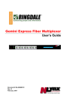
MFR-200 ModuLAN® Fax Receiver from Ringdale® User Manual ModuLAN ® FaxReceiver 200 Fax to Email Server User Manual Copyright Ringdale, Inc. Part number: 62-15280000 Copyright 2006 Ringdale User Manual, 62-15820000 Version 1.0 July 2006 COPYRIGHT Copyright 2006 © Ringdale UK Ltd. All rights reserved. No part of this publication may be reproduced, transmitted, transcribed, stored in a retrieval system, or translated into any language or any computer language, in any form or by any third party, without prior permission of Ringdale UK Limited. DISCLAIMER Ringdale UK Ltd. reserves the right to revise this publication and to make changes from time to time to the contents hereof without obligation to notify any person or organization of such revision or changes. Ringdale UK Ltd. has endeavored to ensure that the information in this publication is correct, but will not accept liability for any error or omission. TRADEMARKS All trademarks are hereby acknowledged. Copyright 2006 Ringdale User Manual, 62-15820000 Page 2 of 28 Table of Contents Table of Contents ............................................................. 3 Introduction .................................................................... 4 Easy Configuration......................................................... 4 Features....................................................................... 4 System Architecture ...................................................... 4 Important Information ...................................................... 5 Installation ...................................................................... 6 Connections .................................................................. 6 Reset Button................................................................. 9 Configuration ..................................................................10 Receiving a Fax...............................................................15 Troubleshooting ..............................................................16 Glossary.........................................................................19 Technical Specifications....................................................20 Trademark Recognition ....................................................20 Legal Notices ..................................................................21 Technical Support............................................................28 Copyright 2006 Ringdale User Manual, 62-15820000 Page 3 of 28 Introduction The Ringdale ModuLAN ® FaxReceiver 200 is designed to receive a fax and convert it into an email to allow distribution that is more convenient and unwanted faxes can be electronically deleted. The Ringdale Fax-Receiver receives the fax and puts it into a mail-server mailbox. From there, you or an administrator can read and redistribute the fax to the appropriate email recipient on the network or print it if necessary. This reduces paper waste, speeds up the communication and distribution of information, allows automatic backup of received faxes and eliminates the need to maintain a fax machine solely for the purpose of receiving faxes. Easy Configuration The setup is done using Telnet, which allows configuration in any network environment like Windows, Unix or Apple. Any Workstation or PC with Telnet capabilities and access to the network can be used to configure the unit. Features External all voltage power supply (100-240 Volts, 50-60 Hz) Extremely low power consumption of less than 5 watts. Remote management from any PC Retains its setup in Flash memory. Powers up in less than 10 seconds. Three login types, CRAM-MD5, LOGIN (AUTH=LOGIN) and non-authenticated. System Architecture The MFR-200 uses a PCMCIA card to connect to the Fax Line; this allows the MFR-200 to be used in any country in the world for which there is a PCMCIA fax/modem card available that fulfills the local standards. The MFR-200 connects directly to an Ethernet 10/100baseTx network via fixed IP or DHCP. Before operating the device a number of parameters have to be set up in the MFR-200 to allow log on to your company or Internet provider's mail server. 3 different login types, CRAM-MD5, LOGIN (AUTH=LOGIN) and non-authenticated. It will try them in that order, and take the first successful login. Copyright 2006 Ringdale User Manual, 62-15820000 Page 4 of 28 Setting up is achieved using the Telnet protocol and a telnet application is available for any operating system. Check your PC, Apple or Unix operator manual. The menu driven setup allows the following parameters to be set up: Required Mailserver (smtp) IP address Logon to mail server (account name) Password for account Destination email address MFR-200 IP address (Fixed or DHCP allocated IP) Network Gateway IP address Not Required Fax return I.D. Fax telephone number Location Name Company Name Password for the MFR-200 A fax is received, a connection with the mail server is established, the fax is decoded and sent to the mail server as a TIFF file for each page embedded in the email. If you are private individual use your email account and password as you use for your existing mail client on your computer, this is all you need. If you are a corporate user we recommend to set up a dedicated email account for the fax receiver i.e. [email protected] and then copy the people to be informed of incoming faxes from this account. This allows you to keep a copy of every received fax in this account for recording purposes. It is up to you if you want to give each fax receiver its own mail account or if you want to use the Location Name to distinguish which device actually received the fax. Since the device only relies on TCP/IP and SMTP it will work in any common network environment. Important Information NOTE: The device is designed to operate in a typical office environment. Choose a location that is: Well-ventilated and away from sources of heat including direct sunlight. Away from sources of vibration or physical shock. Isolated from strong electromagnetic fields produced by electrical devices. Provided with a properly grounded wall outlet. The modem/card must be installed in the top slot. WARNING NOTES: Do not attempt to modify or use the supplied AC power cord if it is not the exact type required. Whenever the chassis cover is to be removed, ensure that the system is disconnected from its power source and from all telecommunications links, networks, or modem lines. Do not operate the system with the cover removed. Copyright 2006 Ringdale User Manual, 62-15820000 Page 5 of 28 Installation The illustration shows the setup of the ports and the diagnostic LEDs. Connections See the drawings on page 7 for installation examples. Plug the PCMCIA modem card into the top slot. Insert your Ethernet RJ45 connection into the LAN jack on the front. NOTE: If you do not have your Ethernet connection plugged in, there will be no lights on power up. The Modem’s RJ11 phone line cable and adapter will plug into the modem card at the rear of the unit, with the other end into the RJ11 phone jack on the wall. Alternatively you may plug the FaxReceiver into a phone splitter. NOTE: If you daisy chain from an outgoing fax machine, it should be set to either don't answer or answer after 4 rings or more so that the fax receiver will pickup first. Connect the power cord to the Switch Mode Power Supply unit socket. Plug the AC cord from the Switch Mode Power Supply into the 110V wall socket. The LEDs are driven by the Ethernet chip so they will only flash if the Ethernet cable is attached. Plug the DC wires from the Switch Mode Power Supply unit into the FaxReceiver. NOTE: It will take about 10 seconds for the FaxReceiver to be ready to accept a fax or telnet connection. Copyright 2006 Ringdale User Manual, 62-15820000 Page 6 of 28 Typical installation replacing an incoming fax machine: Copyright 2006 Ringdale User Manual, 62-15820000 Page 7 of 28 Installation where an outgoing fax machine is required on incoming line: NOTE: If you daisy chain from an outgoing fax machine, it should be set to either not auto answer or answer after 4 rings or more so that the fax receiver will pickup first. NOTE: You should also set the fax machine to tone dialing and not pulse dialing. Pulse dialing causes voltage spikes on the line that can be mistaken for an incoming ring, and the FaxReceiver will attempt to answer. Copyright 2006 Ringdale User Manual, 62-15820000 Page 8 of 28 LEDs The LEDs are itemized as follows: LK (Yellow) LED The Link LED indicates that the port is functionally connected to an external port. It lights up solid when the connected hub is turned on and connected to the LAN. If the LED does not light up, there may be a problem with the cabling or the Ethernet hub. These last two LEDs enable monitoring of the traffic passing through the device. TX (Red) LED The Transmit LED blinks when a data packet is being sent from the FaxReceiver. This would indicate that a fax has been received. RX (Green) LED The Receive LED blinks when a LAN data packet is received. It is normal for this LED to blink all of the time as long as there is any LAN activity. NOTE: The LED's are driven directly by the Ethernet chip. If you do not have the Ethernet cable plugged in, the lights will not light, at power-up. Reset Button When this button is pressed and held for ten seconds on power-up, the FaxReceiver will clear any surplus information it is holding and revert to the default settings. NOTE: If you reset the defaults, it will be necessary to telnet into 11.22.33.44 and reconfigure all of the parameters Copyright 2006 Ringdale User Manual, 62-15820000 Page 9 of 28 Configuration Configuration can be done with any Telnet client, like HyperTerminal or PuTTY. These instructions use the telnet client provided with Windows. These are the steps necessary to configure the FaxReceiver. STEP 1 Connect the FaxReceiver to your network. Its Default IP address is 11.22.33.44. a. On a PC that is on the same physical network as the FaxReceiver, temporarily configure it to an IP Address on the 11.22.33.xxx network. b. Start / Settings / Network Connections c. Local Area Connection / Properties / Internet Protocol (TCP/IP) d. Select Advanced and then add 11.22.33.55, subnet 255.255.255.0 STEP 2 Using Telnet connect to the FaxReceiver. a. Start / Run… b. Type in CMD and press Enter. (This will take you to the command prompt.) c. Type in “telnet 11.22.33.44” and press Enter. d. It will respond “Enter Password”. If a password has not been set, you will *not* be prompted for a password when you telnet into the device. STEP 3 For each line item to be altered, type the number and then the information followed by Enter. First enter a 1 to Setup IP. Copyright 2006 Ringdale User Manual, 62-15820000 Page 10 of 28 Your Network Administrator should provide the Unit IP and Unit Gateway address. 1) This unit IP address .......... 011.022.033.044 – should be changed to an unused IP address on your network. This IP address should be added to your DHCP Server’s static IP address list. 2) Gateway Address ............... 011.022.033.001– should be changed to the IP address of your default gateway. Typically, this is the lowest address on the subnet, for example 192168100.001. 3) DHCP/RARP – This is a toggle. Entering 3 will switch from Disabled to Enabled and back. NOTE: If you use DHCP you must figure out what IP address it obtained. Methods for doing this are covered in the troubleshooting section. Q) Press Q when you have the IP addresses configured. STEP 4 Enter a 2 to setup the SMTP Mailserver. Copyright 2006 Ringdale User Manual, 62-15820000 Page 11 of 28 Your email service administrator should provide the items 2-5. In some cases the Mailserver login name and Destination Email address will be the same email address. 1) Mailserver SMTP IP address – This is the IP address and port of your SMTP server. You should get this from your email administrator or ISP. If you have the name of the SMTP mail server, (i.e., mail.company_name.com) you may be able to ping it in order to get the IP address. 2) Mailserver SMTP IP port – The default is 25. This is most common. Other common ports used are 26, and 2525. 3) Mailserver login name – Often this is an email address. When a fax is received in the email box, it will come from this user. Max 58 characters. 4) Mailserver login password – This is the password for the above email account. There is a maximum of 58 characters. NOTE: passwords are case-sensitive. 5) Destination Email address – This is where the email will be sent to. This can be the same as item 2) or it may be an alias set up to forward to multiple users. Max 203 characters. Q) Press Q when you have the Unit Email settings configured. STEP 5 Enter a 3 to setup the Fax parameters. Copyright 2006 Ringdale User Manual, 62-15820000 Page 12 of 28 1) Fax reply I.D. is sent to the Sending Fax. 20 characters. This is usually displayed on the display of the sending fax after establishing contact, or recorded in its log/print-out. It is not mandatory to have an ID. If it is not set, the FaxReceiver will send an ID of 20 spaces to the distant fax. 2) Fax number – This is the telephone number of the FaxReceiver. Not required. Max 20 characters. 3) Fax Location – This can identify the specific location of the phone line in the building or the city that the FaxReceiver is located in. Not required. Max 28 characters. 4) Company Name – This is the company that is the proud owner of the FaxReceiver. Not required. Max 28 characters. Q) Press Q when you have the Unit Fax settings configured. 4) Reboot after quitting (Disabled) – This setting is to be used if you enable DHCP or RARP and want to get your new IP address now. Ensure you select "Save settings" when quitting after setting the reboot option, otherwise changes you have made will be lost. Alternatively, you can enable the reboot option and quit without saving settings if you to revert back to the previous settings. Copyright 2006 Ringdale User Manual, 62-15820000 Page 13 of 28 5) P) (23) – This will enable the end user to set up a port that the company does not block (e.g. port 80 or even port 25). That means that you will be able to telnet into the FaxReceiver from your desk, enable debug, send a fax to the unit (also from your desk), and figure out what is going wrong. If you change the TELNET port number and don't reboot, the new number takes effect on the *second* new telnet session. i.e. open telnet on default port 23. Change to port 1234 and do a quit/save. Open another telnet session, still on port 23, and quit. All following telnet sessions must be on port 1234. Change Telnet port Change Telnet password – If you do not change this, anyone can access the unit and change the settings. Max 253 characters. For the telnet password, all ASCII and non-ASCII characters may be used except control characters (those with HEX codes below 0x20). Note however that some telnet clients will modify or not pass non-ASCII characters, or may treat them as control commands for the telnet program rather than passing them on, so best to stick with standard keyboard letters, numbers and punctuation marks. Accented characters on non-English keyboards may also be used without problem. Not required. NOTE: passwords are case-sensitive. The FaxReceiver defaults to having no telnet password (factory reset). !) Redirect debug to this screen – This allows you to activate a troubleshooting tool. When activated, telnet will not timeout. More on this screen in the troubleshooting section. When you have completed your changes, press Q to Quit. Q) Quit It will respond: “Do you want to save your changes before quitting (Y/N)” If you will enter y it will save your parameters and report: “All changes saved. Goodbye”. The Telnet connection will then be dropped. If you will enter n it will not save your parameters and report: “Quitting WITHOUT saving changes. Goodbye”. The Telnet connection will then be dropped. NOTE: If you select n it will keep the parameters until the next power cycle or reboot. This will allow you to test the new parameters before saving them. Copyright 2006 Ringdale User Manual, 62-15820000 Page 14 of 28 Receiving a Fax The FaxReceiver is a silent operation device. Connect the FaxReceiver to a fax line. When a fax is received, the Destination Email address will be sent an email. When this occurs, the red Transmit LED will light. The email will have the subject: “Incoming Fax”. The email will have a message similar to this: Ringdale® Fax Receiver RFR 102 (v1.02) - Fax No: 512-869-2621 Location: Hobbiton Remote Fax ID: " 5129301699" It will have an attachment labeled “Page 001.tif (28.6 KB)” You can use the default Windows viewer to see the fax. NOTE: If either your Mailserver (smtp) IP address:port, Mailserver login name or password, the unit’s IP address or Gateway Address are incorrect, the FaxReceiver will not answer the call. Copyright 2006 Ringdale User Manual, 62-15820000 Page 15 of 28 Troubleshooting PROBLEM: LEDs do not flash at power-up CAUSE: Power cord not connected or the Ethernet cable is not attached to a live Ethernet network. The LEDs are driven by the Ethernet chip and will not flash unless an Ethernet network is attached. SOLUTION: Double-check the power plug and the Ethernet connection. PROBLEM: It does not accept a fax. CAUSE: The modem card must be plugged in the top slot. The phone number is incorrect or the LAN connection is disconnected. If it can not reach the SMTP mailserver, it will not answer the call. SOLUTION: Make certain that the modem card is plugged in the top slot. Plug an analog phone into the phone jack at the wall and verify the phone number. Make certain that the LAN connection is attached and the Link LED is solid. The green LED should flash when there is LAN activity to or from it. Check your email parameters with Telnet. In particular, verify the following: 2) 3) 4) 5) 6) 7) Mailserver (smtp) IP address from your SMTP server administrator Mailserver login name often this is your email address Mailserver login password case-sensitive Destination Email address This unit IP address This must be on the same subnet as the Gateway. Gateway Address Typically the same as the above address, but ending with “.001”. After verifying the setup parameters, make certain that you can ping the FaxReceiver. From the same host that you ping the FaxReceiver, you should be able to ping the Gateway Address and the Mailserver (smtp) IP address. PROBLEM: It accepted the fax but did not seem to email the account that we set up. CAUSE: Destination Email address is incorrect. SOLUTION: Verify the Destination Email address. NOTE: Multiple destination addresses are not supported. PROBLEM: I got an "Incoming Fax" email, and when I brought this email up, it had a message that said "OE removed access to the following unsafe attachments in your email". CAUSE: Outlook Express is configured to view attachments as viruses. SOLUTION: In Outlook Express, click on the Tools menu and select Options. Click on the Security tab. Take the check out of "Do not allow attachments to be saved or opened that could potentially be a virus”. Copyright 2006 Ringdale User Manual, 62-15820000 Page 16 of 28 PROBLEM: I am getting poor quality images in the Fax TIFFs. CAUSE: Your image viewer does not properly support tagged image file (TIF) format. The default Windows viewer should work fine. SOLUTION: Try using Imaging or Imaging Preview that comes with Windows. Right-click on the TIFF file and select Open With. It will bring up the Open With window, where you can select Imaging or Imaging Preview. You can also put a check in the "Always use this program to open these files" if you wish. Click OK. PROBLEM: The sending fax reported "POOR LINE CONDITION". SOLUTION: This could mean any of the following: a) The email parameters are not entered correctly. b) The email is being rejected. (email box too full, spam filter parameters) c) Ethernet cable is disconnected. d) There is a poor line condition. QUESTION: How do I reset to the factory default settings? ANSWER: Unplug the power, press the reset button, plugging the power back in while holding reset for 10 seconds PROBLEM: I enabled the DHCP setting, but do not know what address was used. SOLUTION: After the IP address is assigned, ping the address or range of addresses that it could have. Then within 5 minutes, use the ARP -A command to see the IP Addresses assigned in that range. Look for IP Address assigned to the Physical Address that has the last six digits matching the Fax Receiver’s serial number. Example: C:\WINNT\system32>arp -a Interface: 11.22.33.99 on Interface 0x1000003 Internet Address Physical Address Type 192.168.10.1 00-A0-92-bb-23-20 dynamic 192.168.10.23 00-A0-92-65-ec-c4 dynamic 192.168.10.36 00-A0-92-6d-7d-53 dynamic 192.168.10.165 00-A0-92-83-8b-0c dynamic If the Fax Receiver's serial number is 838B0C then the IP Address is 192.168.10.165. Copyright 2006 Ringdale User Manual, 62-15820000 Page 17 of 28 PROBLEM: I have a fax machine used for outgoing faxes connected to a phone splitter with the FaxReceiver. When I try to send a fax, it does not dial. SOLUTION: The fax receiver should not affect the operation of an outgoing fax on the same line. Ensure that the outgoing fax machine is set up for tone dialing and not pulse dialing. Pulse dialing causes voltage spikes on the line that can be mistaken for an incoming ring, and the 1528 will attempt to answer. If there is no incoming fax, and tone dialing is used, the 1528 should not have any effect at all on the operation of the sending fax machine. Another potential problem is that if someone tries to send an outgoing fax whilst a fax is being received, it will mess up the reception. PROBLEM: I have a fax machine used for outgoing faxes connected to a phone splitter with the FaxReceiver. When a fax comes in, the outgoing fax machine answers the call first. SOLUTION: You will need to disable the sending fax's auto-answer, otherwise it will attempt to answer an incoming fax at the same time as the FaxReceiver. PROBLEM: I do not know the IP address of my SMTP server and the ISP is unavailable. SOLUTION: If you have the name of the SMTP mail server, (i.e., mail.company_name.com) you may be able to ping it in order to get the IP address. Try 25 for the port. If that does not work, try 26, and 2525. QUESTION: What does a good debugger trace look like? ANSWER: You should see “authenticated”, “Answered”, “Getting Page”, “CCITT data OK”, “Sending Page to MAIL”, “ok, send it”, “filename="Page001.tif”, “Goodbye”, and “Modem Idle - awaiting call”. QUESTION: My debugger output does not look correct. Can I send it to Tech Support? ANSWER: Yes. Using your mouse, right-click on the blue bar at the top of your telnet session, and select Edit, then Select All. Next right-click on the blue bar at the top of your telnet session, and select Edit, then Copy. Open an email, and do a Paste or Ctrl/v. Send the email to [email protected]. Copyright 2006 Ringdale User Manual, 62-15820000 Page 18 of 28 Glossary CRAM-MD5 - is a challenge-response authentication mechanism (hence "CRAM") defined in RFC 2195 based on the HMAC-MD5 MAC algorithm. It is employed by some SASL implementations, SMTP-AUTH Mail submission agents, and LDAP v3 servers. DHCP – Dynamic Host Configuration Protocol is a client-server networking protocol that provides a mechanism for allocation of IP addresses to client hosts. A DHCP server also provides configuration parameters specific to the DHCP client host requesting, generally, information required by the client host to participate on an IP network. ISP – Internet Service Provider LED - light emitting diode, an electronic device that lights up when electricity is passed through it. MD5 -- MD5 is one of a series of message digest algorithms. It is a widely-used cryptographic hash function with a 128-bit hash value. Internet standard RFC 1321. NPMP -- Network Peripheral Management Protocol. PCMCIA -- Personal Computer Memory Card International Association, and pronounced as separate letters, PCMCIA is an organization consisting of some 500 companies that has developed a standard for small, credit card-sized devices, called PC Cards. PING -- Packet Internet Groper is a protocol primarily used to troubleshoot IP network problems. SMTP -- Simple Mail Transfer Protocol. Used for e-mail, port 25. SMTP gateways provide access to TCP/IP e-mail services. SMTP is an Application layer protocol. Telnet – The Internet standard protocol for remote login. Runs on top of TCP/IP. Comes with most Operating Systems. TIFF - Acronym for tagged image file format, one of the most widely supported file formats for storing bit-mapped images on personal computers (both PCs and Macintosh computers). TIFF graphics can be any resolution, and they can be black and white, gray-scaled, or color. Files in TIFF format often end with a .tif extension. UDP -- User Datagram Protocol, uses best effort, no error-correction, and simple packets: source address -- destination address -- length – checksum. UDP is carried in the Protocol field of IP. Copyright 2006 Ringdale User Manual, 62-15820000 Page 19 of 28 Technical Specifications Network 10/100 base Ethernet LAN Connection RJ45 10baseT Protocols TCP/IP, UDP, SMTP. Ping, NPMP Email login types CRAM-MD5, LOGIN (AUTH=LOGIN) and non-authenticated. Phone Line PCMCIA Fax/Modem Card V.90 or V.92 56K Power Supply External PSU Input: 100 - 240 volts AC Frequency: 47-63 Hz Output: 5 Vdc 2.5 A (uses than 5 watts) Approvals CE, UL and CSA Part No.: 00-18-0528-1100 US 00-18-0528-2400 UK 00-18-0528-2200 DE Trademark Recognition ModuLAN®, Ringdale® and FaxReceiver™ are trademarks of Ringdale, Inc. Windows is a trademark of Microsoft Corporation. eZ80F91 MCU, eZ80 , and Acclaim are trademarks of Zilog. Copyright 2006 Ringdale User Manual, 62-15820000 Page 20 of 28 Legal Notices FCC Information on the V.90 56Kbps Fax/Modem PC Card The Federal Communications Commission (FCC) of the United States restricts uses of modems, and places registration responsibilities on both the manufacturer and the individual user: 1.The modem may not be connected to a party line or to a coin operated telephone. 2.The modem manufacturer must make any repair to the modem to maintain valid FCC registration. 3.Notification to the telephone company is no longer required prior to connecting registered equipment, but upon request from the telephone company, the user shall tell the telephone company which line the equipment is connected to as well as the registration number and ringer equivalence number of the registered protective circuitry. FCC information is printed on a label on the bottom of the modem. FCC Notice This equipment has been tested and found to comply with the limits for a digital device, pursuant to Subpart B and Part 15 of the FCC rules. These limits are designed to provide reasonable protection against harmful interference in a residential installation. This equipment generates and uses radio frequency energy and if not installed and used the instructions, may cause interference to radio communications. However, there is no guarantee that interference will not occur in a particular installation. If this equipment does cause harmful interference to radio or television reception, which can be determined by turning the equipment off and on, the user is encouraged to try and correct the interference by one or more of the following measures: Reorient or relocate the receiving antenna. Increase the separation between the equipment and receiver. Connect the equipment into an outlet on a circuit different from that to which the receiver is connected. Consult the dealer or an experienced radio/TV technician for help. Shielded interconnect cables and a shielded power cord must be employed with this equipment to insure compliance with the pertinent RF emission limits governing this device. Changes or modification not expressly approved by the manufacturer could void the user's authority to operate this equipment. NOTE: The manufacturer is not responsible for any radio or T.V. interference caused by unauthorized modifications to this equipment. Such modifications could void the user's authority to operate the equipment. Copyright 2006 Ringdale User Manual, 62-15820000 Page 21 of 28 Normas Oficiales Mexicanas (NOM) Electrical Safety Statement INSTRUCCIONES DE SEGURIDAD 1. Todas las instrucciones de seguridad y operación deberán ser leídas antes de que el aparato eléctrico sea operado. 2. Las instrucciones de seguridad y operación deberán ser guardadas para referencia futura. 3. Todas las advertencias en el aparato eléctrico y en sus instrucciones de operación deben ser respetadas. 4. Todas las instrucciones de operación y uso deben ser seguidas. 5. El aparato eléctrico no deberá ser usado cerca del agua—por ejemplo, cerca de la tina de baño, lavabo, sótano mojado o cerca de una alberca, etc.. 6. El aparato eléctrico debe ser usado únicamente con carritos o pedestales que sean recomendados por el fabricante. 7. El aparato eléctrico debe ser montado a la pared o al techo sólo como sea recomendado por el fabricante 8. Servicio—El usuario no debe intentar dar servicio al equipo eléctrico más allá a lo descrito en las instrucciones de operación. Todo otro servicio deberá ser referido a personal de servicio calificado. 9. El aparato eléctrico debe ser situado de tal manera que su posición no interfiera su uso. La colocación del aparato eléctrico sobre una cama, sofá, alfombra o superficie similar puede bloquea la ventilación, no se debe colocar en libreros o gabinetes que impidan el flujo de aire por los orificios de ventilación. 10. El equipo eléctrico deber ser situado fuera del alcance de fuentes de calor como radiadores, registros de calor, estufas u otros aparatos (incluyendo amplificadores) que producen calor. 11. El aparato eléctrico deberá ser connectado a una fuente de poder sólo del tipo descrito en el instructivo de operación, o como se indique en el aparato. 12. Precaución debe ser tomada de tal manera que la tierra fisica y la polarización del equipo no sea eliminada. 13. Los cables de la fuente de poder deben ser guiados de tal manera que no sean pisados ni pellizcados por objetos colocados sobre o contra ellos, poniendo particular atención a los contactos y receptáculos donde salen del aparato. 14. El equipo eléctrico debe ser limpiado únicamente de acuerdo a las recomendaciones del fabricante. 15. En caso de existir, una antena externa deberá ser localizada lejos de las lineas de energia. Copyright 2006 Ringdale User Manual, 62-15820000 Page 22 of 28 16. El cable de corriente deberá ser desconectado del cuando el equipo no sea usado por un largo periodo de tiempo. 17. Cuidado debe ser tomado de tal manera que objectos liquidos no sean derramados sobre la cubierta u orificios de ventilación. 18. Servicio por personal calificado deberá ser provisto cuando: A. El cable de poder o el contacto ha sido dañado; u B. Objectos han caído o líquido ha sido derramado dentro del aparato; o C. El aparato ha sido expuesto a la lluvia; o D. El aparato parece no operar normalmente o muestra un cambio en su desempeño; o E. El aparato ha sido tirado o su cubierta ha sido dañada. Copyright 2006 Ringdale User Manual, 62-15820000 Page 23 of 28 FCC Requirements for Telephone-Line Equipment 1. The Federal Communications Commission (FCC) has established rules which permit this device to be directly connected to the telephone network with standardized jacks. This equipment should not be used on party lines or coin lines. 2. If this device is malfunctioning, it may also be causing harm to the telephone network; this device should be disconnected until the source of the problem can be determined and until the repair has been made. If this is not done, the telephone company may temporarily disconnect service. 3. If you have problems with your telephone equipment after installing this device, disconnect this device from the line to see if it is causing the problem. If it is, contact your supplier or an authorized agent. 4. The telephone company may make changes in its technical operations and procedures. If any such changes affect the compatibility or use of this device, the telephone company is required to give adequate notice of the changes. 5. If the telephone company requests information on what equipment is connected to their lines, inform them of: A. B. C. D. The telephone number that this unit is connected to. The ringer equivalence number. The USOC jack required: RJ-11C. The FCC registration number. Items (B) and (D) can be found on the unit’s FCC label. The ringer equivalence number (REN) is used to determine how many devices can be connected to your telephone line. In most areas, the sum of the RENs of all devices on any one line should not exceed five. If too many devices are attached, they may not ring properly. 6. In the event of an equipment malfunction, all repairs should be performed by your supplier or an authorized agent. It is the responsibility of users requiring service to report the need for service to the supplier or to an authorized agent. Copyright 2006 Ringdale User Manual, 62-15820000 Page 24 of 28 Certification Notice for Equipment Used in Canada The Industry Canada label identifies certified equipment. This certification means that the equipment meets certain telecommunications-network protective, operation, and safety requirements. Industry Canada does not guarantee the equipment will operate to the user’s satisfaction. Before installing this equipment, users should ensure that it is permissible to be connected to the facilities of the local telecommunications company. The equipment must also be installed using an acceptable method of connection. In some cases, the company’s inside wiring associated with a single-line individual service may be extended by means of a certified connector assembly (extension cord). The customer should be aware that compliance with the above conditions may not prevent degradation of service in some situations. Repairs to certified equipment should be made by an authorized maintenance facility—in this case, Black Box. Any repairs or alterations made by the user to this equipment, or equipment malfunctions, may give the telecommunications company cause to request the user to disconnect the equipment. Users should ensure for their own protection that the electrical ground connections of the power utility, telephone lines, and internal metallic water pipe system, if present, are connected together. This precaution may be particularly important in rural areas. CAUTION: Users should not attempt to make such connections themselves, but should contact the appropriate electric inspection authority, or electrician, as appropriate. The LOAD NUMBER (LN) assigned to each terminal device denotes the percentage of the total load to be connected to a telephone loop which is used by the device, to prevent overloading. The termination on a loop may consist of any combination of devices, subject only to the requirement that the total of the load numbers of all the devices does not exceed 100. Copyright 2006 Ringdale User Manual, 62-15820000 Page 25 of 28 FEDERAL COMMUNICATIONS COMMISSION AND INDUSTRY CANADA RADIO FREQUENCY INTERFERENCE STATEMENTS This equipment generates, uses, and can radiate radio-frequency energy, and if not installed and used properly, that is, in strict accordance with the manufacturer’s instructions, may cause interference to radio communication. It has been tested and found to comply with the limits for a Class A computing device in accordance with the specifications in Subpart B of Part 15 of FCC rules, which are designed to provide reasonable protection against such interference when the equipment is operated in a commercial environment. Operation of this equipment in a residential area is likely to cause interference, in which case the user at his or her own expense will be required to take whatever measures may be necessary to correct the interference. Changes or modifications not expressly approved by the party responsible for compliance could void the user’s authority to operate the equipment. This digital apparatus does not exceed the Class A limits for radio noise emission from digital apparatus set out in the Radio Interference Regulation of Industry Canada. Le présent appareil numérique n’émet pas de bruits radioélectriques dépassant les limites applicables aux appareils numériques de la classe A prescrites dans le Règlement sur le brouillage radioélectrique publié par le Industrie Canada. Copyright 2006 Ringdale User Manual, 62-15820000 Page 26 of 28 FEDERAL COMMUNICATIONS COMMISSION and INDUSTRY CANADA RADIO FREQUENCY INTERFERENCE STATEMENTS Class B Digital Device. This equipment has been tested and found to comply with the limits for a Class B computing device pursuant to Part 15 of the FCC Rules. These limits are designed to provide reasonable protection against harmful interference in a residential installation. However, there is no guarantee that interference will not occur in a particular installation. This equipment generates, uses, and can radiate radio frequency energy, and, if not installed and used in accordance with the instructions, may cause harmful interference to radio communications. If this equipment does cause harmful interference to radio or telephone reception, which can be determined by turning the equipment off and on, the user is encouraged to try to correct the interference by one of the following measures: • Reorient or relocate the receiving antenna. • Increase the separation between the equipment and receiver. • Connect the equipment into an outlet on a circuit different from that to which the receiver is connected. • Consult an experienced radio/TV technician for help. CAUTION Changes or modifications not expressly approved by the party responsible for compliance could void the user’s authority to operate the equipment. To meet FCC requirements, shielded cables and power cords are required to connect this device to a personal computer or other Class B certified device. This digital apparatus does not exceed the Class B limits for radio noise emission from digital apparatus set out in the Radio Interference Regulation of Industry Canada. Copyright 2006 Ringdale User Manual, 62-15820000 Page 27 of 28 Technical Support Ringdale UK Ltd. Ringdale Inc. and Ringdale GmbH all have Technical Support Departments. North America (8:00 a.m. to 5:00 p.m. CST, Monday to Friday) Fax: 512-930-1699 Direct: 512-288-9080 Toll-free: 888-288-9080 Europe (0900 to 1700 GMT, Monday to Friday) Fax: +44 161 928 7015 Phone: +44 161 928 7014 Before you call: Please have the following information ready: Serial number of the unit. Network Information: IP address of FaxReceiver, Mail Server, and Default Gateway. Type of Fax cards installed in the FaxReceiver. The symptoms of the problem. History of the Problem: o Did the device work for a period of time or fail immediately after installation? o Was any PC option changed (hardware or software) prior to the problem appearing? Address manual comments to: Ringdale Inc. Technical Support 101 Halmar Cove Georgetown, Texas 78628 (512) 288-9080 www.ringdale.com [email protected] Copyright 2006 Ringdale User Manual, 62-15820000 Page 28 of 28