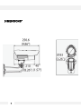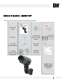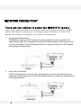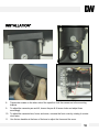
1
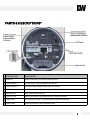
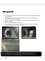
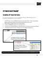
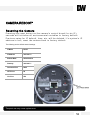
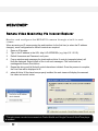
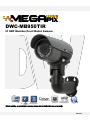
DWC-MB950TIR IP 5MP Weather Proof Bullet Camera Before installing or operating the camera, please read and follow this manual carefully. 08212013 PRECAUTIONS Do not open or modify. Do not open the case except during maintenance and installation, for it may be dangerous and can cause damages. Do not put objects into the unit. Keep metal objects and flammable substances from entering the camera. It can cause fire, short-circuits, or other damages. Be careful when handling the unit. To prevent damages, do not drop the camera or subject it to shock or vibration. Do not install near electric or magnetic fields. Protect the camera from humidity and dust. Protect the camera from high temperature. Be careful when installing near the ceiling of a kitchen or a boiler room, as the temperature may rise to high levels. Cleaning: To remove dirt from the case, moisten a soft cloth with a soft detergent solution and wipe. Mounting Surface: The material of the mounting surface must be strong enough to support the camera. FCC COMPLIANCE This equipment has been tested and found to comply with the limits for a Class B digital device, pursuant to Part 15 of the FCC rules. These limits are designed to provide reasonable protection against harmful interference, when the equipment is operated in a residential environment. This equipment generates, uses, and radiates radio frequency energy, and if it is not installed and used in accordance with the instruction manual, it may cause harmful interference to radio communications. WARNING: Changes or modifications are not expressly approved by the manufacturer. 2 TABLE OF CONTENTS* Introduction.......................................................................................................................................................4 Features........................................................................................................................................................4 Parts .........................................................................................................................................................5-6 Dimensions..................................................................................................................................................7 Inside the Box .............................................................................................................................................8 Installation........................................................................................................................................................9 Network Connection................................................................................................................................... 9 Installation............................................................................................................................................10-13 MEGAPIX Camera Setup...............................................................................................................................14 Installing the IP Scan.................................................................................................................................14 Network Options.........................................................................................................................................15 Camera Reboot..........................................................................................................................................16 MEGAPIX Camera Web Viewer.....................................................................................................................17 Accessing the Web Viewer via Internet Explorer.......................................................................................17 GUI Description .........................................................................................................................................18 Relay Input and Alarm Output Control ..................................................................................................... 19 Digital Zoom ..............................................................................................................................................20 First & Second Stream...............................................................................................................................21 Export Image..............................................................................................................................................22 Instant Recording.......................................................................................................................................23 Controlling the Camera using Virtual Joystick ..........................................................................................24 Client Setup................................................................................................................................................25 MEGAPIX Camera Setup...............................................................................................................................26 System .................................................................................................................................................26-36 Network.................................................................................................................................................37-42 Video / Audio ........................................................................................................................................43-50 Event Handle .......................................................................................................................................51-56 PTZ Control .............................................................................................................................................. 57 System Log ..........................................................................................................................................58-59 Specifications ...........................................................................................................................................60-61 Troubleshooting .......................................................................................................................................62-69 Warranty..........................................................................................................................................................70 Limits & Exclusions.......................................................................................................................................71 3 FEATURES* ONVIF Compliant Profile S 5 Megapixels (2592x1920, 10fps) Resolution Triple Codecs (H.264, MJPEG, MPEG4) with Dual-Stream 1/2.5” 5MP CMOS Sensor (20% Larger Than 1/3” CMOS Sensor) 3.4~10mm Remote Auto Focus Lens 3X Optical Zoom 80ft IR with Intelligent Camera Sync TDN (True Day and Night) Power over Ethernet [PoE] & 8~25VDC, and AC24V Two-Way Audio Micro SD/SDHC Class 10 Card for Emergency Backup IP67 Certified (Weatherproof) Web Server Built-in DNR (Digital Noise Reduction) Programmable Privacy Zones (5) & Motion Detection 4 PARTS & DESCRIPTIONS* [5] 1. Mounting Bracket 2. Pan & Tilt Adjusting screws 3. Lens 4. IR LEDs 5. Sunshield Cover 6. Camera Module [6] [4] [3] [1] 5 [2] PARTS & DESCRIPTIONS* Camera Part Description 1 RS485 +/- RS485 connections for remote camera control 2 Sensor Inputs +/- Connect up to 2 sensor inputs to the camera 3 Alarm Output +/- Connect 1 Alarm output control from the camera 4 SD Card Slot Micro SD card slot for local storage (not included) 5 Network Port RJ45 Cable Connection Port 6 Audio In/ Out Built-in Microphone and Audio Amplifier output connector 7 Power Ports DC Power port and AC + DC Cable power connectors available 8 Reset Switch Reset the camera to factory default values 6 DIMENSIONS* 7 INSIDE THE BOX – MB950TIR* The following items are included with the MEGAPIX camera. 8 NETWORK CONNECTION* There are two options to power the MB950TIR camera. Use a PoE-enabled switch to connect data and power through a single cable and begin viewing and recording images instantly. A non -PoE switch will require an adaptor for power transmission. 1. Using a PoE-Enabled Switch The MEGApix Camera is PoE-Compliant, allowing transmission of power and data via a single Ethernet cable. PoE eliminates the need for the different cables used to power, record, or control the camera. Follow the illustration below to connect the camera to a PoE-enabled switch using an Ethernet cable. 2. Using a Non-PoE Switch If a PoE-enabled switch is not used, use a power adaptor for power transmission and nonPoE switch for data transmission. Follow the illustrations below to connect the camera without a PoE-Enabled Switch. 9 INSTALLATION* 1. Use the camera’s mounting template to mark and drill the mounting holes. 3. Mount the camera’s arm support onto the mounting plate. 4. To connect all appropriate cables to the camera and complete the installation, unscrew the back cover of the camera. 2. Fix the mounting plate to the surface using the three (3) provided screws, washers, and wall anchors. 10 INSTALLATION* 5. Remove the spindle fork connecting the camera module to the mounting bracket by pushing in the spindle. 6. Screw the spindle fork on to the camera. 7. Set the camera onto the arm by pushing the spindle and placing the fork on the spindle. 11 INSTALLATION* 8. Tighten the screws on the other side of the spindle to lock the camera on to the mounting bracket. 9. To adjust the camera’s pan and tilt, loosen the pan & tilt screw locks and adjust them accordingly. 10. To adjust the camera’s lens, focus, and zoom, unscrew the front cover by rotating it counter clock-wise. 11. Use the two handles at the base of the lens to adjust the focus and the zoom. 12 INSTALLATION* 12. You may also use the 2nd Video output located near the camera’s lens for easy adjustment during installation. 13. After adjusting the lens, remove a drying agent pack from one of the silver packages stored inside the accessories package*. 14. Remove the sticker from the drying agent pack and insert it in the front under the lens as shown in the image*. 15. Screw the front cover back on to the camera. 16. If using wide angle, shift the camera’s hood back to avoid blocking the view. Loosen screws and shift back or forward as necessary. * The drying agent pack should be replaced each time the camera is opened (front or back). Be sure to complete all work before inserting drying agent pack & replacing the cover. Drying agent packs will become ineffective if exposed to open air for more than 10 minutes. 13 IP FINDER SOFTWARE* Installing IP Scan Software IP Finder searches for all the available Digital Watchdog devices currently connected to your network. 1. Install IP Scan to find the MB950TIR Cameras on the local network. The IP Scan software can be found on the included CD. Run IP Scan and install it onto your PC. 2. When setup is complete, launch the IP Scan software. 3. To find your MB950TIR cameras, click the Scan button. 4. You can use the DWScan software to adjust the camera’s IP Address and Network Settings 5. To change the camera’s Network Settings, press the Change Settings button. *Install the IP Finder to a computer located on the same Subnet Mask as the MEGAPIX camera. 14 IP FINDER SOFTWARE* DHCP The Dynamic Host Configuration Protocol (DHCP) is a network configuration protocol that allows a device to configure automatically according to the network it is connected to. If your network supports DHCP and your MEGAPIX camera is set to DHCP, IP Finder will automatically find and set your MEGAPIX camera to correspond with your network requirements. Static Static IP addresses are recommended when using a network that does not support DHCP or when setting your device to be accessed externally via the internet. If Static is selected, you must manually enter the correct network settings for your MEGAPIX camera. The settings will correspond with your network. To set your camera to a static IP address, we recommend that you (1) setup the camera to DHCP, (2) allow it to configure itself according to your network, and (3) change the settings to a static IP address. 1. To set your MEGAPIX camera to Static, highlight the desired device from the search results list, and click on Configuration. In the “Network Configuration” window, make sure Static is selected. 2. Enter the following information: IP Address, Netmask, Gateway, and Preferred DNS. 3. Click Apply and Reboot to save all changes. DDNS Dynamic Domain Name Server is a feature that allows you to use a specific URL instead of an IP address to access your MEGAPIX camera. This feature is optional. It may require a subscription and fee. 1. To use the DDNS feature, check the box next to Use DDNS. 2. Select the server you wish to use. *Some servers may require a subscription and fee. 3. If applicable, enter the User ID and Password. 4. Click Apply and Reboot to save all changes. 15 CAMERA REBOOT* Resetting the Camera Pressing the reset button on the camera’s control board for six (5) seconds will initialize all environmental variables to factory default. Previous setup for IP default, time, etc. will be deleted. If a system’s IP address is lost, reset the camera back to factory default. The following are the default network settings. IP Mode DHCP IP Address 192.168.1.2 Subnet Mask 255.255.255.0 Gateway 192.168.1.1 Command Port 6002 HTTP Port 80 Live Port 554 * Frequent use may cause system error. 16 WEBVIEWER* Remote Video Monitoring Via Internet Explorer Monitor and configure the MEGAPIX camera through a built -in web viewer. When accessing an IP camera using the web interface for the first time (or when the IP address changes), some configuration for ActiveX controls are required. 1. Open an IE browser 2. Type in the IP address in the URL: http://<IP ADDRESS> (e.g. http://10.1.21.53). 3. Default Username and Password: root/ pass. 4. Pop-up windows and messages for download/run Active X controls (examples below) will likely be displayed. Select Install or Run to all such messages. Click on the add-on message and choose Run Add-on. 5. Repeat the above until all ActiveX controls have been initiated. Once the process is complete, the Live View will be displayed in IE. 6. when all Active X files have been properly installed, the web viewer will display the camera’s live video and control center. * The web viewer can also be accessed via Firefox Mozilla and Google Chrome if QuickTime player is installed. 17 WEBVIEWER* GUI Description 18 WEBVIEWER* Relay Input & Alarm Output Control The MB950TIR supports 2 Sensor Inputs and 1 Alarm Control Output. Use the camera’s Control bar and status indicators to manage the camera’s relay and alarm inputs and outputs. The View Size controls adjust the viewable screen size in Live View. The Zoom feature can be used once one of the zoom view modes is selected. See page 20 for more information. Record and Snapshot will capture video/snapshots to the local hard drive. Digital Out will trigger a digital output signal (e.g. to an alarm). Full Screen will display video in full screen mode. Click the Esc key to exit Full Screen mode. SD Card shows the status of the SD card. Digital In Alert will display when a digital in alert has been triggered. Motion Detection Alert will display when motion detection has been triggered. 19 WEBVIEWER* Digital Zoom The Digital Zoom feature allows zooming in on a specific area. To control the Camera’s Digital Zoom: 1. When using the View Size controls, a magnifying glass icon will replace the mouse pointer icon. 2. To magnify a specific area, place the magnifying glass icon over the desired area and left click the mouse. Additional left mouse clicks will continue to magnify wherever the mouse is placed. 3. To zoom out, right click the mouse. 4. If the mouse is moved to the edge of the image window, the mouse icon will change to a white, triangular icon. 5. This icon allows moving the view using electronic PTZ if the functionality is available and enabled. 20 WEBVIEWER* First Stream & Second Stream The MB950TIR supports multiple simultaneous streams (4 profiles) The Streams can be switched from the camera’s web viewer by selecting the corresponding stream from the drop down menu in the Steam Control option. The stream’s current resolution and framerate information will be displayed in the information section. To setup the different streams: a. Go to ‘Setup’ at the top right-hand corner of the screen. The setup menu will appear. b. Go to Video/Audio > Video Settings c. Select the number of profiles you would like to assign the camera. d. All selected profiles will appear under the Quality Setting Section. Here you can modify each steams’ resolution, codec, bitrate, and max framerate. e. Press ‘Save’ to save all settings. See page 43 for more information. * Option not available on DW Optimized Firmware 21 WEBVIEWER* Export Image Export a screenshot of the current live video to your computer. 1. 2. Make sure the directory path has been setup. To do so: 1. Go to Client Settings at the top right-hand corner of the screen. 2. Press ‘Select Path’ to select the directory where all exported images will be saved to. Settings will be saved automatically. 3. Click on the ‘Live View’ link at the top right-hand corner of the screen to return to the camera’s live display. To export an image of the camera’s current live view, press the button at the top control bar. An image with time stamp will automatically be saved as a JPEG file. 22 WEBVIEWER* Instant Recording Record live video to your local drive. To Setup Instant Recording Make sure the directory path is setup. To do so go to Client Settings at the top right-hand corner of the screen and press ‘Select Path’ To Start and Stop Instant Recording To Start, press the icon on the control menu bar. A window will appear to notify you instant recording has begun. The button will blink red indicating you are currently recording video. To Stop, press the 23 button again. The video file will appear in the designated directory path. WEBVIEWER* Controlling the Camera using the Virtual Joystick Use the different buttons in the Pan/ Tilt Controller to adjust the camera’s position, zoom and focus, and control the camera’s PTZ functions. To control the Camera’s Pan, Tilt, and Zoom 1. PTZ Directional Buttons-When the camera is in zoom, use the directional arrows to control the zoom screen’s movement and focus on a specific area of the camera’s field of view. Press the home button in the center of the control to return the camera to its default home position. 2. Speed- Adjust the camera’s movement speed. Select from 1-6, default value is 4. 3. Preset- the preset button allows you to go to or setup any number of presets for the camera. 4. Preset buttonsa. Set current position as a preset. b. Go to a previously set preset. 5. Zoom- Use the Zoom spectrum to zoom in and out and adjust the camera’s field of view. Click on the left side of the spectrum line to zoom out of the image. Click on the right side of the spectrum line to zoom into a section of the image. [1] [2] [3] [b] 6. Focus Control Button- The focus of the camera can be controlled by clicking the Focus spectrum line. [a] 7. Iris Control Button- Iris control button. The iris of the camera can be controlled by clicking the Iris spectrum line. [5] [6] [7] 24 WEBVIEWER* Client Setup It is recommended that you setup your camera’s client settings the first time you access the camera to prevent any feature malfunction in the future. The Client Setup provides options to modify the recording path, streaming protocol and buffering time. Streaming protocol and buffering time relate to streaming settings for the web UI on the client PC. These settings are only applied for the browser session, and don’t persist after the browser is closed. Settings apply to a specific PC; they are not universal. Recording Path Recording Path is used to define the directory where snapshot images and video will be stored. Streaming Protocol RTP/RTSP over HTTP is the default. This is the most flexible setting in that it streams using port 80 which should likely require no client router configuration. RTP over UDP may use less bandwidth than the other options, but it may also result in inferior video quality since packets may be lost in transmission (more common over WAN) and may require additional router client configuration for UDP traffic. See section 5 Router/Firewall Configuration for more information on network configuration considerations. Buffering Time Buffering Time can be increased if video appears to lag due to network latency. However, an increased buffer will result in increased lag between real time. 25 WEBVIEWER* Setup > System> Information The Setup interface is primarily used for viewing and configuring the IP camera’s settings. To access the Setup page, click the Setup link at the top right-hand corner of the camera’s live display. The camera’s system information will be displayed including: Model name Firmware Version Serial Number WiFi Status MAC Address & IP Address Information Subnet Mask Information Gateway Information Primary and Secondary DNS Information To return to the Live View page, click the Live View link in the right hand corner*. * Configuration changes require clicking the SAVE button. Otherwise, changes will not be applied. 26 WEBVIEWER* Setup > System> Generic Settings Use the Generic Settings Page to modify the camera’s Name, Date & Time format, Sensor Input Type, LED Management, HTTP Port Setup and Language Selection. Camera Name- Enter a camera name if a specific name is desired System Time-3 options are available: Manual: insert time manually PC Time: set to the current PC time Network Time Server: periodically synchronizes with a time server For Network Time Server two standard options are provided. If another time server is preferred, then choose others from the list and add the address of the time server which will be used. Digital Input-This defines the method by which the digital in sensor operates. If the normal condition is open (N.O.), then the alarm will be triggered when the circuit is closed. The opposite applies for N.C. 27 WEBVIEWER* Setup > System> Generic Settings Use the Generic Settings Page to modify the camera’s Name, Date & Time format, Sensor Input Type, LED Management, HTTP Port Setup and Language Selection. LED- The camera LED lights can be enabled or disabled. The bullet model has an additional setting which controls operation of an external IR LED source. The External IR Output Level controls the circuit voltage which is used to turn on/off the external IR LED. NOTE: Refer to the external IR LED manufacturer’s recommendation to properly set the External IR Output Level. Low = Active Low: no voltage turns on the external IR LED; voltage turns off the IR LED High = Active High: voltage turns on the external IR LED; no voltage turns off the IR LED HTTP Port- To use a non-default port, change the HTTP Port value. This port is used by the camera’s web server and HTTP streaming. Language- Currently English, Simplified Chinese, Czech, French, German, Russian and Italian are available. 28 WEBVIEWER* Setup > System> User Account Management User accounts can be added, edited or deleted via the controls in the left corner. Users are assigned to a group (admin, operator or viewer). To edit or delete an account, highlight the account in the User List window and click the edit/delete button. After making changes, click SAVE to apply changes. 29 WEBVIEWER* Setup > System> Maintenance Use the Maintenance setup page to upgrade the firmware, Import or Export Settings, Reset the camera to factory default, or reboot the camera. Firmware Upgrade- The firmware can be upgraded using the web UI or an SD card. After upgrading, the ActiveX controls and browser cache should be cleaned to prevent old controls & pages from being used. IP and User Account settings can be preserved by checking the appropriate boxes. After selecting the new firmware file, click Update to proceed. Messages that the camera is upgrading and rebooting will follow during the upgrade. Perform the steps in “Clean the ActiveX and IE Cache & History” below, using IP Scan change the network settings (if applicable), then check the System Information page to verify the upgrade has been completed successfully. 30 WEBVIEWER* Setup > System> Maintenance Use the Maintenance setup page to upgrade the firmware, Import or Export Settings, Reset the camera to factory default, or reboot the camera. Firmware Upgrade Using the SD Card- The SD card should be empty of any existing files before proceeding. 1. Rename the firmware file to ev-fw.bin, and copy the file to the SD card. 2. Insert the card into the camera’s SD card slot. 3. Power on the camera, and wait about 1 minute. 4. The green power LED will flash quickly during the upgrade, become stable briefly and slowly blink while performing a reboot. 5. Check IP Scan to verify the camera is available (IP address may have changed to factory default, 192.168.1.2). 6. Remove the SD card. 7. After web UI access is once again available, review the System Information page to verify the upgrade has completed successfully. 31 WEBVIEWER* Setup > System> Maintenance Use the Maintenance setup page to upgrade the firmware, Import or Export Settings, Reset the camera to factory default, or reboot the camera. Clean the ActiveX and IE Cache & History- After upgrading, the ActiveX controls and IE cache & history should be cleared to prevent old pages and controls from being used. 1. Close all instances of IE and open 1 IE window. 2. In the right corner, select Tools->Manage Add-ons 3. In the Manage Add-ons window, select “All add-ons” 4. Scroll down and find Unknown Company, highlight one of the ActiveX controls, and click the More Information link. 5. In the More Information window, click Remove to clear the ActiveX control from IE. 6. Repeat this for the remaining ActiveX components. 7. To clear the cache and browsing history, in the IE menu select Tools->Internet Options. Click the Delete button in Browsing History. 32 WEBVIEWER* Setup > System> Maintenance Use the Maintenance setup page to upgrade the firmware, Import or Export Settings, Reset the camera to factory default, or reboot the camera. Import/ Export Camera Configuration- Export will save the camera’s configuration settings to the PC in an archive file. To import, first use Browse to select a camera’s exported configuration file. Next click Import to proceed with replacing the current camera settings with the settings in the configuration file.* Restore Factory Default- Replaces factory default settings via the web UI. Network and/or user account settings can be saved if the corresponding check boxes are selected. Reboot Device- Press the Reboot button to restart the camera. It is recommended to reboot the camera when major settings have been configured such as after importing settings. *Configuration settings can only be imported from a camera of the same model and using the same firmware version. Otherwise, the import will apply the factory default settings. 33 WEBVIEWER* Setup > System> Local Storage The MB950TIR supports local recording to a micro SD Card. Use the Local Storage setup page to format and setup the card properly. Format: Format will format the card. Note: contents of the SD card will be lost. Double click on folders to go up/down a directory level. 34 WEBVIEWER* Setup > System > Recording/ Snapshot There are 2 methods of recording: Event -Triggered and Continuous Recording. Both can be used simultaneously. Cyclic Recording offers options for whether to overwrite old recordings when space on the storage reaches capacity. Event Triggered Recording- When recording is done via event triggers, Record Setting will define how the recording is performed. Stream Source will only display currently enabled video profile streams. The pre-alarm and post-alarm buffer are defined in terms of size (MB). The min/max for the settings are based on the stream’s resolution & bit rate. So, if the stream source is a small resolution size, then the pre-alarm and post-alarm min/max settings will be less than min/max values for a high resolution stream. Continuous Recording- Currently continuous recording only records to SD card. Checking Recording Schedule will display the scheduling settings which can be used to define when continuous recording should occur. 35 WEBVIEWER* Setup > System > Recording/ Snapshot There are 2 methods of recording: Event -Triggered and Continuous Recording. Both can be used simultaneously. Cyclic Recording offers options for whether to overwrite old recordings when space on the storage reaches capacity. Snapshot Settings- Snapshot recording will record a group of snapshots. The maximum value for Pre-alarm and Post-alarm time is 5 seconds. Cyclic Recording- The camera can be configured to overwrite the oldest existing recording on SD Card and Network Storage by checking the appropriate option. Continuous Cleanup will delete the oldest files as needed when the storage becomes full. The process will basically delete what is needed for current recording. The Preserve option will delete up to the number of days defined for this setting. If the storage becomes full and all the files fall within the X days defined, then recording will stop. Recording will continue once files are deleted manually or when files become eligible for deletion (greater than X days). 36 WEBVIEWER* Setup > Network> IP Settings Use the IP Settings page to set the camera to DHCP or Static IP. If Static is selected, manually enter the camera’s IP address, subnet mask, Gateway and primary and secondary DNS information. In the IP Setting tab, select DHCP or Static IP for the camera. If using static, then enter the appropriate settings for your environment. Please confirm all network related settings with the network administrator prior to making any changes. a. IP Address- Enter the static IP Address of the camera b. Subnet Mask- default is 255.255.255.0 c. Gateway- your router’s external (public) IP address. It is used when accessing the camera from outside the network. The router will channel your data to the correct destination even if it is on a different subnet mask. d. To obtain a static IP Address and network information, contact your Internet Service Provider or Network Administrator. 1. DNS- Enter Primary DNS and Secondary DNS. The Domain Name Server translates web addresses to IP addresses. 37 WEBVIEWER* Setup > Network> WLAN Settings Only wireless dongles from the manufacturer are supported. In the WLAN setting tab, click the Enable Wi -Fi option to enable WiFi. Any WiFi changes will only be applied after clicking the Save button in the IP Setting tab. Auto Scan can be used to scan available networks. An available network can be selected by clicking the option and entering a password if required. Manual can be used to directly configure WiFi settings. Auto Setup Manual Setup In the IP Setting tab, set the appropriate IP settings for the wireless network. After clicking Save, the camera will reboot with the new wireless settings. The camera will no longer be accessible via the wired network. Disabling WiFi or removing the WiFi USB antennae will enable the wired network port. 38 WEBVIEWER* Setup > Network > Streaming The camera can stream using UDP, TCP or HTTP. The client application connecting to a camera can direct which protocol to use. The method of streaming will likely determine the need and extent of any router configuration that may be required. The port settings all relate to camera ports. If streaming outside of a LAN (e.g. to the internet), then routers on both the camera and client side need to provide necessary access for these ports. The camera will stream via HTTP by default, which will use the HTTP port as defined in the System – Generic Settings (80 by default). Streaming via HTTP often requires little or no router configuration. If the client application uses RTP over RTSP/TCP, then the camera will stream using the RTSP Port, 554 by default. RTP over UDP will stream using the RTP Video Port, starting at 6002 and can increment . 39 WEBVIEWER* Setup > Network > Streaming The camera can stream using UDP, TCP or HTTP. The client application connecting to a camera can direct which protocol to use. The method of streaming will likely determine the need and extent of any router configuration that may be required. Video and audio server ports only need be changed if a network has security or operational restrictions using these ports. In most cases, the RTP/RTCP video and audio should use the default values. While the RTP/RTCP audio/video ports by default are 6002-6005, this represents the starting point for client connections. If 1 client is connected, then this connection would use 6002-6005, but a 2nd connection would then use 6006-6009. This may require proper router configuration if using the web UI outside of a LAN. Maximum Viewers refers to concurrent uses. Connections beyond this value will receive an error upon connection. Multicasting allows sending a message or data to a group via a single message. The multicasting parameters are only for configuring a camera to use multicasting. A networking environment that supports multicasting must be setup.* * Please contact your network administrator for additional information. 40 WEBVIEWER* Setup > Network > DDNS DDNS is used to map a dynamically assigned IP address (a device using DHCP) with a hostname. If the IP camera uses DHCP, a DDNS service can provide a hostname for use with the IP camera. Registration with a DDNS service provider (ddns.nu, dyndns.org) is required for use of this feature. 1. To use DDNS, select the Use DDNS checkbox. 2. Select one of the DDNS System Names from the drop down list. 3. Enter Username & Password. The Username & Password must be registered at the DDNS site. 4. Enter Host Name. 5. Click Save to save all changes. 41 WEBVIEWER* Setup > Network > Access Filtering Access filtering can be used to allow or deny access by IP addresses. Set the Filter Type to either Allow All or Deny All. Exceptions can be added to the chosen filter type. IP addresses can be entered as a single IP, by network or a range of IP addresses. The network option uses the CIDR subnet mask format. 42 WEBVIEWER* Setup > Video / Audio > Video Settings Use the Video Settings page to select the number of profiles the camera will stream simultaneously and setup each of the profiles. Power Frequency- Use this setting to adjust the camera’s display has flickering issues. This may occur due to artificial lighting and can be adjusted by modifying the Power Frequency. Select from 50GHz or 60GHz. Max Resolution- Select the camera’s resolution. By default, the camera is setup to 1080p (2.1 Megapixels). The higher the resolution, the lower the maximum frame rate will be (for example, the camera can stream up to 10 fps on 5 Megapixel resolution). 1 to 5M (2592x1920) with a maximum 10fps for both Stream 1 and 2. The 5M option limits ROI to 2, and recording via the camera (e.g. SD card) is disabled. Minilux mode uses noise cancelation technology to provide clearer image quality in low lux conditions. Enable TV Output- TV Output can be enabled with SDTV or HDTV options available. SDTV = CVBS output HDTV = YPbPr output When TV Output has been enabled, 2 video profiles will be enabled. Profile 2 will change to settings which will be used for the video out display (e.g. D1 resolution). Profile 1 settings will not be modified. Show/ Hide Time Stamp & Camera Name- When enabled, the video will display the time stamp and camera name at the top left-hand corner of the display area. * Option not available on DW Optimized Firmware 43 WEBVIEWER* Setup > Video / Audio > Video Settings Use the Video Settings page to select the number of profiles the camera will stream simultaneously and setup each of the profiles. Profile Setting- The Video Profile Settings control the ROI (Region of Interest) characteristics. The ROI video is streamed via RTSP protocol. See the “Streaming ROI” section for more on viewing ROI video. The number of available ROI profiles for viewing can be set by selecting the appropriate option button. 4 Profile defines each stream with a VGA resolution (640x480), while 1 Profile and 2 Profile settings provide some options for resolution. Settings for specific ROI profiles can be found in the Video Quality Setting section. ROI profile 1 & 2 are preconfigured profiles which have some settings that are configurable (e.g. FPS). All profiles offer Constant Bit Rate (CBR) or Variable Bit Rate (VBR) mode. The GOP (Group Of Pictures) can also be adjusted. The GOP is based on the FPS setting. For example, if the FPS is 20 and the GOP setting is 2, then the GOP is 40 frames. A GOP is comprised of one I frame and the remainder are P frames. 4 Profile defines each stream with a VGA resolution (640x480). In the Region Size settings, the image has a mask covering area that will not be displayed; the lighter shaded area will be what is displayed for the ROI. To adjust the ROI, click & drag the window or click within the masked area to reposition. * Option not available on DW Optimized Firmware 44 WEBVIEWER* Setup > Video / Audio > Audio Settings Select the desired audio codec. The Bitrate is configurable for some codecs. Encoder Type-Select from the available options: NONE, AAC, G.711 u-law (default), G.711 a-law , G.726. Bitrate- If AAC or G.726 are selected as encoder type, setup the bitrate. Select form 16, 32, or 40 Kbps. Line-in Gain- Adjust the volume of input audio from 0 to 10. Default value is 6. Line-Out Gain- Adjust the volume of output audio from 0 to 10. Default value is 6 45 WEBVIEWER* Setup > Video / Audio > Color Settings Use the Color Settings to adjust the Day/ Night Settings as well as image color control settings. Day/Night Settings: IR Cut Filter The Auto Mode (AE) allows adjusting the light sensor’s sensitivity to day/night conditions to fine tune the IR cut filter operation when the Auto Mode (Light Sensor) isn’t optimal for a specific environment. In Transfer Threshold are 2 settings: From Day to Night and Back to Day. From Day to Night has a range (+10 Bright to -10 Dark) which can be used to adjust the sensitivity of switching from day to night. A larger From Day to Night value will result in a switching to Night mode in lighter conditions, a lower value requires darker conditions to switch. Back to Day also provides a range (+2-+12) which adjusts the sensitivity of the switch from night to day. This value relates to the From Day to Night; the switch to day mode is based on the From Day to Night + Back to Day values. NOTE: Auto Mode (AE) doesn’t differentiate between IR light and visible light. Subsequently, IR light can cause the IR-Cut filter to switch back to Day mode. While in night mode, if an object is close the image will appear bright from the IR light and result in the Luminance Metering to register a high value which can switch the camera back to Day mode. This is due to Auto Mode (AE) using image brightness. So, the camera shouldn’t use this setting in environments where objects are close creating a “bright” image. Alternatively, set the Back to Day to a high value to counteract this behavior. 46 WEBVIEWER* Setup > Video / Audio > Color Settings Select the desired audio codec. The Bitrate is configurable for some codecs. Color & Sensor Settings: Image settings for both day and night are available via the Day & Night Time Profile tabs. The relevant settings will be applied to the camera based on the camera’s present mode of operation (e.g. day or night). In the Color Settings Tab, adjust the following options: Brightness: select values from 0~255. Default value is 128. The higher the number the brighter the image will appear. Contrast: select values from 0~255. Default value is 128. The higher the number the stronger the contrast between the dark spots and bright spots in the image will appear. Saturation: select values from 0~255. Default value is 128. The higher the number the warmer the colors in the image will appear. Sharpness: select values from 0~255. Default value is 100. The higher the number the sharper lines in the image will appear. Flip: flip horizontally (top to bottom) Mirror: flip vertically (right to left) 47 WEBVIEWER* Setup > Video / Audio > Color Settings Select the desired audio codec. The Bitrate is configurable for some codecs. Color & Sensor Settings: Image settings for both day and night are available via the Day & Night Time Profile tabs. The relevant settings will be applied to the camera based on the camera’s present mode of operation (e.g. day or night). In the Sensor Settings Tab, adjust the following options: AE Range Limit: enabling exposes an upper/lower limit list of exposure values for configuration Enabling also disables AEC & AGC settings and hides the setting controls AEC: Automatic Exposure Control; disabling enables Manual Exposure Max Exposure: maximum possible exposure time Manual Exposure: sets specific exposure time AGC: Automatic Gain Control; disabling enables Manual Gain Max Gain: maximum possible gain Manual Gain: sets specific gain setting AWB: Auto White Balance. Location: indoor/outdoor setting to provide more accurate exposure for an indoor or outdoor environment. BLC: Back Light Compensation; image EV (Exposure Value) can be increased to compensate for background lighting. WDR: Wide Dynamic Range; used for high contrast lighting; some camera models only have Medium and High setting. Noise Reduction: image noise compensation; manual allows user to define level of noise reduction (0 none; 255 max). While noise reduction will smooth pixilation (usually in dark areas), too much may result in blurring. 48 WEBVIEWER* Setup > Video / Audio > Text Overlay The video display format can be changed by selecting one of the available timestamp formats and enabling display of the camera name . Select from the following available text display options: yyyy-mm-dd hr:min:sec mm-dd-yyyy hr:min:sec mmmm-dd-yyyy hr:min:sec Choose to enable or disable attaching the camera’s name to the text overlay. 49 WEBVIEWER* Setup > Video / Audio > Privacy Masking Privacy mask can be used to block out areas from view and triggering motion detection. Up to 5 privacy masks can be applied; each mask can be 80 x 45 in size. 1. 2. 3. 4. 5. Check the box next to the Privacy Masking you want to edit. Check the Draw button next to the Mask’s name. Select the color of the mask you want to setup (black by default). Using your mouse, draw the mask on the camera’s display window. Use the block’s handles to adjust the size or move the mouse over the area and click/drag to move the mask. 6. You can also use the X/ Y/ W/ H values to manually adjust the position and size of the mask. 7. The masked area will be blocked from the image (and motion detection) with the color set in Color of Mask. 50 WEBVIEWER* Setup > Event Handle> Event Rule The Event Rule page is used to define actions (e.g. record to SD card) in response to the triggering of an event (e.g. motion detection ). Rule Name is a user defined name for a user defined trigger/action. Trigger Type- select what action will trigger the set command. Select form the available options: Motion Detection – Set action will be activated when the camera detects motion. If selected, check which motion areas will apply to this rule. See page 52 for information on how to setup motion detection. Digital Input –Set action will be activated when the camera detects a sensor is activated. Select which sensor you want to setup as the trigger to the rule. Network Loss – Set action will be activated when the camera detects network loss. Periodical Times – Set action will be activated every set amount of seconds. Default time is set to every 60 seconds. Period Time is a time interval during which an event cannot be triggered. For example, if Period Time is set to 60, then after a specific event is triggered (e.g. motion detection), that event can only be triggered after 60 seconds. This applies only to a user-defined event. If 2 motion detection events have been configured (e.g. MD1 and MD2), then if MD1 is triggered, MD2 can still be triggered regardless of MD1’s Period Time setting. 51 WEBVIEWER* Setup > Event Handle> Event Rule The Event Rule page is used to define actions (e.g. record to SD card) in response to the triggering of an event (e.g. motion detection ). Action determines what action you would like the camera to perform once the selected trigger has been detected. Select from the following options: Digital Output – The camera will activate the digital output when the trigger set is detected. The Digital Output option has a Duration parameter which relates to the length of time the digital output should be triggered. E-mail Notifications – The camera will send an e-mail notification to a set destination when the trigger set is detected. See page 53 for more information on setting up e-mail notifications. TCP Notification and HTTP Notification – The camera will send a TCP or HTTP Notification to a determined server when a selected trigger is detected. These notification options have a Message Text box where you can enter what text you would like to be sent with the notification (Max 32 characters). Snapshot – The camera will send a snapshot image to a network storage when the trigger selected has been detected. The Snapshot will include a total of three images: a Pre-Alarm snapshot (3 seconds before the alarm), the alarm snapshot, and a post-alarm snapshot (3 seconds after the alarm). See page 36 for information on the snapshot settings. Please note that available actions depend on the trigger type. For example, you will not be able to select to send an e-mail notification on network loss. Click SAVE in the main Event Rule screen to save any changes. 52 WEBVIEWER* Setup > Event Handle> Event Server The Event Server page has configuration options for event notification & action using email, network storage, FTP, TCP and HTTP. E-Mail Settings – Use this setup page to enter the information for an SMTP server for the e-mail notifications feature. Enter the SMTP server for Server Address and all additional relevant details. The username may only contain alphanumeric characters and the underscore character, “_”. Use the ‘Test’ button to send a test e-mail to make sure the server has been properly set up. Select whether the e-mails sent from the camera will have event information in the message. Select to customize the e-mail’s default message. You can use this option to personalize the email messages sent from the camera. Enable or disable snapshot attachments with event notifications to e-mails sent from the camera. 53 WEBVIEWER* Setup > Event Handle> Event Server The Event Server page has configuration options for event notification & action using email, network storage, FTP, TCP and HTTP. Network Storage– Use this setup page to enter set up a Network Storage device. Server Type- Select whether the network storage you want to setup is NFS or Samba. Server Address- enter the server’s URL or IP address. Folder Path- enter the folder destination in the network storage where you would like all notifications from the camera stored. Username and Password- enter the username and password for the server. Connection Status- indicates whether the connection between the camera and the server is available or not. Press the ‘Refresh’ button to make sure the camera is successfully connected to the server. 54 WEBVIEWER* Setup > Event Handle> Event Server The Event Server page has configuration options for event notification & action using email, network storage, FTP, TCP and HTTP. TCP/ HTTP Recipient– Use this to setup the recipients for TCP and HTTP Notifications from the camera. The TCP and HTTP Recipient allows event notifications to be sent from the camera to a TCP or HTTP server. A triggered event will use the settings defined in TCP/HTTP Recipient to send a notification to the TCP or HTTP server. The notification will include any message text that was defined in the Event Rule. See page 39-40 for more information. TCP Recipient requires an IP address and port for the server which will process the notification via TCP socket. TCP Server Address & port- enter the server’s URL or IP address and port information for the TCP Server. Connection Test- Use the ‘Test’ button to make sure the proper information has been saved on the camera and it is properly connected to the TCP Server. HTTP Recipient requires an HTTP server URL along with credentials which will process the notification sent via HTTP. HTTP Server Address- enter the server’s URL or IP address and port information for the HTTP Server. Username and Password- enter the username and password for the server. Connection Test- Use the ‘Test’ button to make sure the proper information has been saved on the camera and it is properly connected to the HTTP Server . 55 WEBVIEWER* Setup > Event Handle> Motion Detection To use motion detection, motion detection should be enabled and at least one motion detection area enabled. Checking the box for an Area (e.g. Area 1) enables it. Make sure “Motion Enable” is checked. The camera supports up to three (3) different motion detection areas. To set them up: Select an area by checking the box next to it. Click on the ‘Draw’ button. Using your mouse, draw the zone on the camera’s display window. Use the block’s handles to adjust the size or move the mouse over the area and click/drag to move the motion zone. You can also use the X=horizontal, Y=vertical, W=width, H=height values to manually adjust the position and size of the motion zone. Set the camera’s sensitivity to the motions. Select from a scale of 0 to 100; default is 50. The lower the number the less sensitive the camera will be to motion. Object size determines the size of an area that will trigger motion detection. The value represents percentage of the motion detection area which will result in motion detection. Select from a scale of 0 to 100; default is 25. 56 WEBVIEWER* Setup > PTZ Control > Serial Settings PTZ settings can be applied if the camera will interact with a PTZ device. Pelco P and D and transparent protocols are supported as well as RS-485 and RS-422 communication modes. Please refer to the PTZ device’s required settings to configure the web UI PTZ settings. 57 WEBVIEWER* Setup > System Log > View Log The System Log displays system and event details. The System Log has information specifically related to basic system messages (e.g. startup, shutdown) Event Log contains information related to events triggered. You can click the ‘Refresh’ button at any time to upload the latest and most up to date log report. 58 WEBVIEWER* Setup > System Log > Remote Log Settings The System Log displays system and event details. The System and/or Event log data can be sent to another server. The syslog service is used to send the message data, and the camera will use UDP port 514 (syslog protocol) to transmit the data. The remote server which will receive messages must have an application which will receive and manage the syslog messages. If using Windows, an application such as Kiwi Syslog Server or Splunk can be used to receive and manage the data. To enable remote logging,: Check the Enable box Provide the corresponding log server IP address. * The remote server’s firewall or a router may block incoming UDP syslog traffic from the camera. If the remote server’s monitoring application is not receiving message data from the camera, verify the router or firewall are not blocking incoming traffic. 59 SPECIFICATIONS* IMAGE Image Sensor 1/2.5” 5MP CMOS Sensor (20% Larger Than 1/3” CMOS Sensor) Total Pixels 2016 (H) x 1108 (V) Minimum Scene Illumination 0.0 Lux Lens 3.4~10mm Varifocal DC Iris Lens Optical Zoom 3x Optical Zoom IR Distance 80ft Range IR with Intelligent Camera Sync Angle of View Horizontal: 40 (wide) - 25 (tele) AUDIO Compression and Sampling Rate G.711/ G.726/ AAC Input/ Output 1x Line In and 1x Line Out OPERATIONAL DNR (Digital Noise Reduction) Off, Auto, Manual (0~255) Auto Gain Control 2x~128x, Max Gain, Manual BLC (Back Light Compensation) -2.0EV ~ +2.0EV, Off WDR (Wide Dynamic Range) Off, Low, Medium, High Day and Night Auto, Day (Color), Night (B/W) , Activate with Digital Input Brightness 0~255 Alarm Notifications File Upload via FTP and E-mail, E-mail Notifications with Snapshot attachment, External Output Activation, File Recording to SD Card, Remote FTP or NAS Sharpness 0~255 Mirror & Flip Off/ On Memory Slot 24 hours recording to Micro SDHC Card (4GB-32GB) *Card not included Recording Schedule Setup Continuous, Event, Pre- & Post-Alarm Recording to SD Card, FTP Server, and Network Storage Chroma (Hue & Saturation Settings) 0~255 60 SPECIFICATIONS* NETWORK DW Optimized Firmware Full Firmware LAN 802.3 Compliance 10/100 LAN Video Compression Type H.264 H.264, MPEG4, MJPEG (Super Fine ~ Low) Resolution 10fps @ 2560x1920 (5MP) @2592x1920(5MP) / 20fps@2048x1536(3MP) / 30fps@1920 x1080(2MP) Frame Rate Up to 10fps Up to 30fps based on Resolution Stream Capability Dual-Stream at Different Rates and Resolutions IP IPv4, IPv6 Protocol TCP/IP, HTTP, DHCP, PPPoE, HTTPS, ICMP, ARP, RTSP, NTP, UDP, NTP, SMTP, RTP, RTCP, 3GPP, SAMBA (NAS) Maximum User Access 10 Users Memory Slot Local SDHC Card Backup- 24 hours recording to Micro SDHC Card (4GB-32GB) ONVIF Conformance Yes, Profile S Web Viewer Supported OS: Windows XP, Windows Vista, Windows 7, MAC OS Supported Browser: Internet Explorer 8 or higher, Google Chrome, Mozilla Firefox, Safari Video Management Software DW Spectrum ENVIRONMENTAL Operating Temperature -40°C ~ 60°C (-40°F ~ 140°F) Operating Humidity Less than 80% (Non-Condensing) Storage Temperature -29°C ~ 55°C (-20°F ~ 131°F) IP Rating IP67 (Vandal Proof, protects against dust & high pressure water) Other Specifications CE, FCC, RoHS Electrical Power Requirement DC 8~25V, AC 24V, PoE (IEEE802.3af Class 3) Power Consumption Max 8.9W, 600mA Mechanical Housing Material Aluminum Housing Dimensions 95(W) x 95(H) x 251(D)mm (3.74 x 3.74 x 9.88 Inch) Weight 3.97 lbs 61 TROUBLESHOOTING Before sending your camera for repair, check the following or contact your technical specialist. Streaming video from the camera using an RTSP Streaming. Video can be streamed to a video player (e.g. VLC) via RTSP protocol using the standard RTSP port number 554. The URL is in the following format: rtsp://[IP ADDRESS]/rtpvideo[1-4].sdp Replace with the appropriate IP address. rtpvideo1-4 represent video profiles with different characteristics. For more information on video profiles, see Video/Audio > Video Setting”. Using VLC for example, select Media from the menu bar and Open Network Stream. Next specify IP address of the camera and stream profile. Click Play and video will begin streaming in the video player. WARNING: firewalls and other network security may prevent video streaming. AUTHENTICATION If Streaming authentication has been enabled in Network -> Streaming Then a username/password must be supplied with the RTSP URL rtsp://USERNAME:PASSWORD@[IP ADDRESS]/rtpvideo[1-4].sdp 62 TROUBLESHOOTING Before sending your camera for repair, check the following or contact your technical specialist. Viewing Motion JPEG from the camera in a Browser Basic streaming from the camera to a browser can be done using the mjpg.cgi call. Microsoft IE does not support this function. IE doesn’t support the server-push implementation, so Firefox is recommended for use with mjpg.cgi. Other browsers (e.g. Chrome) may also work. First, configure the target video stream profile to use MJPEG encoding type. If multiple video profiles use MJPEG, then the profile parameter should also be included; this is discussed below. In the browser enter the mjpg.cgi call. Substitute the camera IP/URL for <IP ADDRESS>: http://<IP ADDRESS>/stream/mjpg.cgi The user will be challenged for a username and password; this is required and can’t be disabled. The username/password can be included with the URL avoiding the username/password pop-up window. Use the following format (substitute root:pass with appropriate username:password): http://root:pass@<IP ADDRESS>/stream/mjpg.cgi If multiple profiles are using MJPEG codec, then the profile=n parameter should be included to specify which video stream profile to use. Substitute the stream profile number (e.g. profile=2 for camera video profile 2) for n: http://<IP ADDRESS>/stream/mjpg.cgi?profile=n 63 TROUBLESHOOTING Before sending your camera for repair, check the following or contact your technical specialist. Digital Input Electrical Information Ambient Temperature: 25º C TTL signal only External voltage source: 3-5Vdc ±10% TTL signal high/low level: 3.3V Max. current: 20mA 64 TROUBLESHOOTING Before sending your camera for repair, check the following or contact your technical specialist. Digital Output Electrical Information Ambient temperature: 25º C External power input: ≤ 12Vdc Continuous load current: 100mA Peak load current: 240mA (100ms / 1 shot) 65 TROUBLESHOOTING Before sending your camera for repair, check the following or contact your technical specialist. I can’t find my MEGAPIX camera on the IP Finder software. Is the PoE cable connected properly? Make sure the cable is tightly connected at both ends. It should make a “click” sound when connected properly. Make sure the cable is intact and there are no cuts or exposed wires. If Yes, are the camera’s LED lights turned on and blinking? The camera’s LED lights indicate that the camera is powered on. Blinking LED lights indicate that the camera has finished booting up and is transmitting data. If Yes, is the internet working properly? Make sure you can connect to the internet with other devices on the network (ex. Your Computer). Your internet could be temporarily down. If Yes, if using a power adaptor, does it meet camera’s power requirements? Power Requirements: DC12V (5.16W, 430mA), PoE Ports (Class 2, less than 7W) If Yes, if using PoE Switch, is it connected to a proper internet outlet and operating properly? Make sure the PoE Switch is connected to a router/modem and the ports that have devices connected to them have a green LED on. If Yes, is the computer on the same network as the MEGAPIX camera? Camera and computer should be connected to the same router. Contact your network adminitrator if you have more than one network available. If Yes, try pinging the IP camera’s default IP address 192.168.1.123 From your desktop, go to Start > Programs > Accessories > Command Prompt. Type “ping 192.168.1.123” and press Enter. If you get the message “Request timed out,” cmaera is not connected. Camera is connected if you get data. If Yes, try connecting the camera to a differt port in the PoE Switch. That specific Switch Port may be damaged or currently not working properly. If Yes, try resetting the camera to default settings. Press the 2 buttons in the back together and hold for 5 seconds. The camera will return to factory deafult with default IP address 192.168.1.123. If your network supports DHCP, the camera will be found using the IP Finder software with an IP address that matches your network’s requirements. 66 TROUBLESHOOTING Before sending your camera for repair, check the following or contact your technical specialist. I can’t connect to my MEGAPIX camera through the Web Browser Are the camera’s LEDs on and blinking? The camera’s LED indicates the camera is On. If the LED blinks, the camera has finished booting up and is transmitting data. If Yes, is the internet working properly? Make sure you connect to the internet with other devices on the network (ex. Your Computer). Your internet could be temporarily down. If Yes, is the computer on the same network as the IP camera? Camera and computer should be connected on the same router. Contact your network administrator if you have more than one network available. If Yes, try pinging the MEGAPIX camera’s IP address as it appears on the IP finder. From your desktop, go to Start > Programs > Accessories > Command Prompt. Type “ping” followed by the camera’s IP address; then, press Enter. If you get the message “Request timed out,” camera is not connected. If you get data back, that means the camera is connected. If Yes, try connecting the camera, to a different port in the PoE Switch. That specific Switch Port may be damaged or currently not operating properly. If Yes, check your security settings on your internet browser. Try adding the camera’s IP address to the trusted sites list in your Internet Options. *Setup may vary depending on the browser you use. 67 TROUBLESHOOTING Before sending your camera for repair, check the following or contact your technical specialist. I can’t see the live video of my MEGAPIX camera. Are you trying to view the camera’s video from an Internet Explorer browser? Make sure you have the minimum PC requirements to view the MB950TIR camera. *See below for more information. If Yes, did you install ActiveX files? When you connect to your MEGApix camera for the first time, your browser will ask you to install ActiveX. Make sure your Web Browser’s security settings do not block pop-up windows and allows ActiveX files to be installed and used. *Setup may vary depending on the browser you use. If Yes, make sure nothing is blocking the MB950TIR camera’s lens. Are you trying to view the camera’s video from a different browser than Internet Explorer (ex. Google Chrome, Mozilla Firefox, MAC Safari)? If Yes, at least one of the streams of the camera must have Codec set to MJPEG. Go to the camera’s setup menu. Select Stream Settings. Select one of the streams and change its codec to MJPEG. Click Save and Reload to save changes. Go back to live screen and at the bottom of the screen, select the stream you have set to MJPEG. Live video will start streaming to your web browser. Web Viewer Specifications Minimum Requirements for PC CPU Intel P4 2.0GHz Dual Core RAM More than 1GB HDD 200 GB Required for Saving Clip Image OS Microsoft Windows XP or Higher Resolution Higher than 1024X768 68 TROUBLESHOOTING Before sending your camera for repair, check the following or contact your technical specialist. Setting the IP Address for your PC Dynamic Host Configuration Protocol (DHCP) is the default setting for the camera. If the MEGAPIX camera is connected to a DHCP network and the camera’s IP Configuration Mode is set to DHCP, the server will automatically assign an IP address to the camera. If the camera is using DHCP, the default IP address will be 192.168.1.123, and the default subnet mask will be 255.255.255.0. The MEGAPIX camera can also connect to the web viewer using a static IP address. This will allow you to set your own IP address manually. Setup the Network Protocol on your PC. 1. Go to Network icon on your PC. 2. Right-click and select Properties. 3. Double-click Local Area Connection. 4. Click Properties. 5. Double-click Internet Protocol Version 4 (TCP/IPv4). 6. Select Obtain an IP address automatically to set the computer to a dynamic IP address, or select Use the following IP address to set the computer to a static IP address. 7. If the option Use the following IP address has been selected, setup the IP address as 192.168.1.XXX. The last three digits should be a number between 1 and 254. 69 WARRANTY INFORMATION* Digital Watchdog (referred to as “the Warrantor”) warrants the Camera against defects in materials or workmanships as follows: Labor: For the initial two (2) years from the date of original purchase if the camera is determined to be defective, the Warrantor will repair or replace the unit with new or refurbished product at its option, at no charge. Parts: In addition, the Warrantor will supply replacement parts for the initial two (2) years. To obtain warranty or out of warranty service, please contact a technical support representative at 1-866-446-3595 Monday through Friday from 8:30AM to 8:00PM EST. A purchase receipt or other proof of the date of the original purchase is required before warranty service is rendered. This warranty only covers failures due to defects in materials and workmanship which arise during normal use. This warranty does not cover damages which occurs in shipment or failures which are caused by products not supplied by the Warrantor or failures which result from accident, misuse, abuse, neglect, mishandling, misapplication, alteration, modification, faulty installation, set-up adjustments, improper antenna, inadequate signal pickup, maladjustments of consumer controls, improper operation, power line surge, improper voltage supply, lightning damage, rental use of the product or service by anyone other than an authorized repair facility or damage that is attributable to acts of God. 70 LIMITS & EXCLUSIONS* There are no express warranties except as listed above. The Warrantor will not be liable for incidental or consequential damages (including, without limitation, damage to recording media) resulting from the use of these products, or arising out of any breach of the warranty. All express and implied warranties, including the warranties of merchantability and fitness for particular purpose, are limited to the applicable warranty period set forth above. Some states do not allow the exclusion or limitation of incidental or consequential damages or limitations on how long an implied warranty lasts, so the above exclusions or limitations may not apply to you. This warranty gives you specific legal rights, and you may also have other rights that vary from state to state. If the problem is not handled to your satisfaction, then write to the following address: Digital Watchdog, Inc. ATTN: RMA Department 5436 W Crenshaw St Tampa, FL 33634 Service calls which do not involve defective materials or workmanship as determined by the Warrantor, in its sole discretion, are not covered. Cost of such service calls are the responsibility of the purchaser. 71 Headquarters Office: 5436 W Crenshaw St, Tampa, FL 33634 Sales Office: 16220 Bloomfield Ave., Cerritos, California, USA 90703 PH: 866-446-3595 | FAX: 813-888-9262 www.Digital-Watchdog.com [email protected] Technical Support PH: USA & Canada 1+ (866) 446-3595 International 1+ (813) 888-9555 French Canadian 1+ (514) 360-1309 Technical Support Hours: Monday-Friday 9:00am to 8:00pm Eastern Standard Time