1
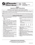
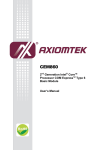
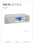
12000 COM Express Carrier Board Sealevel Systems, Inc. Sealevel.com Phone 864.843.4343 Contents Introduction .............................................................................................................................................................. 4 Features ..................................................................................................................................................................... 5 Before You Get Started ............................................................................................................................................. 5 What’s Included ..................................................................................................................................................... 5 Advisory Conventions ........................................................................................................................................... 5 Optional Items ....................................................................................................................................................... 6 Function Block Diagram ........................................................................................................................................... 9 Connector Layout ................................................................................................................................................... 10 Component Layout ................................................................................................................................................. 12 Specifications .......................................................................................................................................................... 14 Mechanical Dimensions ...................................................................................................................................... 14 Environmental Specifications ............................................................................................................................. 14 Power Supply ....................................................................................................................................................... 14 Status LEDs D3 .................................................................................................................................................... 14 CMOS Battery ....................................................................................................................................................... 15 I2C EEPROM ......................................................................................................................................................... 15 Connector Descriptions ......................................................................................................................................... 16 Power Input.......................................................................................................................................................... 17 Module Type 6 Connector Pinout Rows A and B ............................................................................................... 18 Module Type 6 Connector Pinout Rows C and D .............................................................................................. 19 Subsystems of COM Express™ Connector Rows A&B ....................................................................................... 20 High Performance Serial Communication Ports ............................................................................................ 20 HDA Audio........................................................................................................................................................ 26 LAN 10/100/1000 ........................................................................................................................................... 27 USB 2.0 Ports.................................................................................................................................................... 28 Serial ATA™ ...................................................................................................................................................... 28 ©Sealevel Systems, Inc. SL9245 12/2013 12000 Manual 2 PCI Express® Mini Card ................................................................................................................................... 28 Additional Features ................................................................................................................................................ 30 Power Button input ............................................................................................................................................. 30 Power States ........................................................................................................................................................ 30 Reset Button ........................................................................................................................................................ 30 Status LEDs .......................................................................................................................................................... 31 Test Points ........................................................................................................................................................... 31 Software Support .................................................................................................................................................... 32 Where to Get Software ........................................................................................................................................ 32 SeaCOM Windows Installation ............................................................................................................................ 33 Upgrading to the current SeaCOM driver .......................................................................................................... 34 Linux Support ...................................................................................................................................................... 34 Serviceable Parts ..................................................................................................................................................... 35 Serial Port 3 Configuration ................................................................................................................................. 35 Input Current Protection Fuse ............................................................................................................................ 35 Disk Drive Installation......................................................................................................................................... 36 COM Express Module Installation ...................................................................................................................... 38 Appendix A - Handling Instructions ...................................................................................................................... 42 Appendix B – Electrical Interface ........................................................................................................................... 43 Appendix C – Asynchronous Communications .................................................................................................... 44 Appendix D - Mechanical Drawing ........................................................................................................................ 45 Warranty .................................................................................................................................................................. 47 ©Sealevel Systems, Inc. SL9245 12/2013 12000 Manual 3 Introduction COM Express is a widely supported implementation of Computer on Module (COM) design. The COM Express architecture reduces the complexity, cost and time required for custom computer system design by combining the processing, memory, video, Ethernet and USB functionality in a small, highly-integrated module. COM Express modules install on a carrier board that provides the application specific I/O and external connectors best suited for the system requirements. Sealevel COM Express carrier boards leverage the company’s years as a leader in I/O and communication products to provide carrier board and full system solutions in the fastest time possible. Common I/O features include serial, analog and digital I/O. Sealevel’s extensive library of proven I/O circuits can be included as required to meet the specific I/O count, voltage ranges and connector types. The 12000 is compatible with Basic and Compact form factor Type 6 pinout COM Express modules. The 12000 is based on the PICMG COM Express (COM.0 Rev. 2.0) specification and follows the PICMG COM Express Carrier Design Guide (CDG) where possible. (See 6.3 Carrier Board Design on page 12). There are many features that make the 12000 stand out from other boards on the market such as the compact design, integrated EEPROM, next generation integrated UART and a high degree of customizability. ©Sealevel Systems, Inc. SL9245 12/2013 12000 Manual 4 Features The following features are included on the 12000 carrier board. 1 Display Port Compatible Video Output 2 Gigabit Ethernet Ports 2 RS-232 Serial Ports 1 RS-485 Serial Port 5 USB 2.0 Ports 1 Audio Line Input 1 Audio Line Output 256 Byte I2C EEPROM (with unique 128-bit serial number) Power and SATA Activity LED Indicators Reset Button PCI Express Mini Card Expansion (half-length only) Power Switch Input Accepts 2.5” SATA Disk Drive 18-36 VDC Input Before You Get Started The 12000 carrier board is shipped with the following items. If any of these items are missing or damaged, please contact Sealevel for replacement. 12000 carrier board BK1043 SSD Mounting Bracket HW1191 Mylar Board Protector 10A Blade Fuse Installed CMOS Battery Installed Warning - The highest level of importance used to stress a condition where damage could result to the product or the user could suffer serious injury. Important– The middle level of importance used to highlight information that might not seem obvious or a situation that could cause the product to fail. Note – The lowest level of importance used to provide background information, additional tips, or other non-critical facts that will not affect the use of the product. ©Sealevel Systems, Inc. SL9245 12/2013 12000 Manual 5 Depending upon your application, you are likely to find one or more of the following items useful with the 12000. All items can be purchased from our website (www.sealevel.com) or by calling our sales team at (864) 843-4343. AC/DC Power Supply (Item# TR140) The TR140 is a desktop style power supply rated for 100-240VAC 50-60Hz input and 24VDC output at 2.7 amps. The latching Molex connector prevents accidental cable disconnection and unintended power interruption. The input socket accepts an IEC-320-C13 plug. Choose the appropriate input cord to use in other countries. Solid State Drive (Item# SSD-32GMS) The SSD-32GMS is a SATAII Solid State Drive featuring MLC NAND flash. Many more drives are available to find the correct match of capacity, durability and operating temperature range. DB9 Female to DB9 Male Extension Cable, 72” Length (Item# CA127) The CA127 is a standard DB9F to DB9M serial extension cable. Extend a DB9 cable or locate a piece of hardware where it is needed with this six foot (72) cable. The connectors are pinned one-to-one so the cable is compatible with any device or cable with DB9 connectors. The cable is fully shielded against interference and the connectors are molded to provide strain relief. Dual metal thumbscrews secure the cable connections and prevent accidental disconnection. 9 Female to DB25 Male Standard RS-232 Modem Cable, 72” Length (Item# CA177) The CA177 is a standard AT-style RS-232 modem cable with a DB9 female connector on one end and a DB25 male connector on the other end. Simply connect the DB9 female connector to the DB9 serial port on the 12000 carrier board, and then connect the DB25 male connector to your RS-232 serial modem or other compatible RS-232 serial device. The six foot cable is fully shielded with dual thumbscrews at each connector. The molded connectors integrate strain relief to prevent damage to the cable or connectors. All DB9 modem control signals are implemented and the cable is pinned to EIA-232 standards. ©Sealevel Systems, Inc. SL9245 12/2013 12000 Manual 6 10 Position to DB9 Male Adapter Cable (Item# CA152) The CA152 provides a panel mount DB9 male connector for the 10 Position RS-485 connector on the 12000 carrier board. DB9 Female to 9 Screw Terminal Block (Item# TB05) The TB05 terminal block breaks out a DB9 connector to 9 screw terminals to simplify field wiring of serial connections. It is ideal for RS-422 and RS-485 networks, yet it will work with any DB9 serial connection, including RS-232. The TB05 includes holes for board or panel mounting. The TB05 is designed to connect directly to the 12000 DB9 serial ports or any cable with a DB9M connector. DB9 Female to 5 Screw Terminal Block (RS-422/485) (Item# TB34) The TB34 terminal block adapter offers a simple solution for connecting RS-485 field wiring to the CA152 DB9 Male connector. The terminal block is compatible with 2wire and 4-wire RS-485 networks. ©Sealevel Systems, Inc. SL9245 12/2013 12000 Manual 7 Panel Mounted Adapter with Locking USB Port (Item# SL-PM) The SL-PM easily adds a SeaLATCH locking USB port to your enclosure, faceplate or bulkhead. This gives you the freedom to add a locking USB port wherever it is needed. Internal USB Cable for 2mm Molex Connectors, 14” (Item# CA471) The CA471 is an embedded USB cable. One end has a 1x5 2mm Molex connector for connecting to the onboard latching USB header. The other end has a 1x4 2mm Molex connector for connecting to an SL-PM or a Sealevel embedded USB product. The CA471 is 14" in length. CAT5 Patch Cable, 7' in Length (Part# CA246) Standard 7' CAT5 Unshielded Twisted Ethernet Pair Patch Cable (RJ45) with blue jacket. CAT5 Patch Cable, 10' in Length (Part# CA247) Standard 10’ CAT5 Unshielded Twisted Pair Ethernet Patch Cable (RJ45) with blue jacket. ©Sealevel Systems, Inc. SL9245 12/2013 12000 Manual 8 Function Block Diagram ©Sealevel Systems, Inc. SL9245 12/2013 12000 Manual 9 Connector Layout Reference Designator Function SW1 Serial Port 3 Termination Option Switch J12 Serial Port 3 Mode Control Jumper J13 CMOS Battery Backup Connection/Reset Jumper J2, J5, J6, J8, J4 USB 2.0 Ports P3 10/100/1000 LAN RJ45 x2 Connector P5 Serial Ports DB9 x2 Connector J11 DC Power Input Connector P8 DisplayPort Connector P2 Audio Connector D3 Power/SATA Act Status LEDs J9 Power Button Header ©Sealevel Systems, Inc. SL9245 12/2013 12000 Manual 10 Reference Designator Function CN1 PCIe Mini Card BAT1 RTC Backup Battery J1 COM Express Connectors P1 Serial Port 3 Header BP1 P9 ©Sealevel Systems, Inc. SL9245 12/2013 Reset Button Proprietary Expansion Bus 12000 Manual 11 Component Layout Legend Reference Designator Function U4 IDT 92HD73C Audio Codec U7 Intel 82574IT PCIe Network Interface Controller U10 IDT PCIe Clock Buffer U17 Board Controller U24 Oxford PCIe to Quad UART ©Sealevel Systems, Inc. SL9245 12/2013 12000 Manual 12 Legend Reference Designator Function U34 12V Power Supply Controller U35 5V Power Supply U36 3.3V Power Supply SW1 Serial Port 3 Termination Option Switch J12 Serial Port 3 Mode Control Jumper J13 CMOS Battery Backup Connection/Reset Jumper J2, J5, J6, J8, J4 USB 2.0 Ports P3 RJ45 x2 Connector P5 DB9 x2 Connector J11 DC Power Input Connector P8 DisplayPort Connector P2 Audio Connector D3 Power/SATA Act Status LEDs J9 Power Button Header ©Sealevel Systems, Inc. SL9245 12/2013 12000 Manual 13 Specifications Board length 7.69 inches (19.54 cm) Board Width 4.35 inches (11.05 cm) Specification Operating Storage 1 Temperature Range -40 to 85 ºC (-40 to 185 ºF) Humidity Range 10 to 90% R.H. Non-Condensing -40 to 105 ºC (-40 to 221 ºF) 10 to 90% R.H. Non-Condensing Supply line 18 VDC-36VDC Rating (Dependent on COM Express Module and input voltage and load) 375mA-2150mA A two position LED is present at location D3. The GREEN LED is on when 12V power supply is powering the COM Express module. The RED SATA Activity LED flashes when there is SATA activity. 1 Temperature range is for the 12000 board and its components excluding COM Express module. ©Sealevel Systems, Inc. SL9245 12/2013 12000 Manual 14 The 12000 includes a 3V DC type CR2032 battery that supplies the RTC and CMOS memory of the COM Express CPU module. Danger of explosion if battery is incorrectly replaced – Replace only with the same or equivalent type recommended by the manufacturer. Dispose of used batteries according to the manufacturer’s instructions. To fulfill the requirements of the EN 60950, the 12000 incorporates two current-limiting devices (resistor and diode) in the battery power supply path. An I2C EEPROM is present on the 12000 carrier board. The EEPROM is 2 kbit (256Bytes) and operates at 400 kHz. The contents of the EEPROM can be edited and read via a software API. This can be used storage of configuration information, serial numbers and used to verify system credentials for licensed software. ©Sealevel Systems, Inc. SL9245 12/2013 12000 Manual 15 Connector Descriptions The following I/O connectors use industry standard pin outs for maximum compatibility. Reference Designator Function Connector Type P8 Video Output DisplayPort P3 10/100/1000 (Gigabit Ethernet) Network Connections RJ-45 P5 RS-232 Serial Ports DB9 Male J2 USB 2.0 Device USB Type A J5 USB 2.0 Device USB Type A J6 USB 2.0 Device USB Type A J8 USB 2.0 Device P2 Audio Input/Output CN1 PCIe Mini Card P4 SATA Disk Drive USB Type A 3.5mm Stereo Headphone PCIe Mini Card Edge 22 Pin SATA The following I/O connectors use non-standard pin outs. However, Sealevel Systems offers accessory cables that provide industry standard pin outs. Reference Designator Function Accessory Cable Terminating Connector P1 RS-485 Serial Port CA152 DB9 J4 USB 2.0 Device CA471 + SL-PM USB Type A J9 Power Button Input CA254 Momentary Switch The following connectors are not intended for use in this product. Do not use. J3 J10 P6 P9 P9 is intended for Sealevel Systems internal use only. Several pins of P9 carry high DC voltages and provide direct electrical connection to the COM Express module and other ESD sensitive electronics. Extreme care should be taken to ensure no conductive materials come in contact with any pins of P9. Touching a conductive material to any contacts of P9 could result in irreparable damage to the circuit board and/or COM Express module. It is acceptable to place ESD safe tape over the contacts of P9 (on both sides of the circuit board) to provide protection from inadvertent damage. The 12000-KT is shipped with the captive SATA drive pre-installed on the product. The aluminummounting bracket holds the drive on the board and a sheet of Mylar protects the circuit board from ©Sealevel Systems, Inc. SL9245 12/2013 12000 Manual 16 damage due to small vibrations and movements of the disk drive. If the drive is removed or replaced for any reason, the protective Mylar sheet and disk drive bracket must be reinstalled. The 12000 carrier board is designed to operate from 18VDC up to 36VDC. The current draw varies across this range and is heavily dependent on the COM Express module, peripheral devices and installed software. The connector at J11 is Molex PN 39-30-1040. Use Molex 39-01-2040 connector housing with Series 5556 Mini-Fit Jr crimp terminals. CKT # Signal 1 + Positive DC Power 2 + Positive DC Power 3 - Negative DC Power (GND) 4 - Negative DC Power (GND) ©Sealevel Systems, Inc. SL9245 12/2013 Name 12000 Manual 17 (Signals shaded orange are not used) Pin Row A Pin Row B Pin Row A Pin Row B A1 A2 A3 A4 A5 A6 A7 A8 A9 A10 A11 A12 A13 A14 A15 A16 A17 A18 A19 A20 A21 A22 A23 A24 A25 A26 A27 A28 A29 A30 A31 A32 A33 A34 A35 A36 A37 A38 A39 A40 A41 A42 A43 A44 A45 A46 A47 A48 A49 A50 A51 A52 A53 A54 A55 GND(FIXED) GBE0_MDI3GBE0_MDI3+ GBE0_LINK100# GBE0_LINK1000# GBE0_MDI2GBE0_MDI2+ GBE0_LINK# GBE0_MDI1GBE0_MDI1+ GND(FIXED) GBE0_MDI0GBE0_MDI0+ GBE0_CTREF SUS_S3# SATA0_TX+ SATA0_TXSUS_S4# SATA0_RX+ SATA0_RXGND(FIXED) SATA2_TX+ SATA2_TXSUS_S5# SATA2_RX+ SATA2_RXBATLOW# (S)ATA_ACT# AC/HDA_SYNC AC/HDA_RST# GND(FIXED) AC/HDA_BITCLK AC/HDA_SDOUT BIOS_DIS0# THRMTRIP# USB6USB6+ USB_6_7_OC# USB4USB4+ GND(FIXED) USB2USB2+ USB_2_3_OC# USB0USB0+ VCC_RTC EXCD0_PERST# EXCD0_CPPE# LPC_SERIRQ GND(FIXED) PCIE_TX5+ PCIE_TX5GPI0 PCIE_TX4+ B1 B2 B3 B4 B5 B6 B7 B8 B9 B10 B11 B12 B13 B14 B15 B16 B17 B18 B19 B20 B21 B22 B23 B24 B25 B26 B27 B28 B29 B30 B31 B32 B33 B34 B35 B36 B37 B38 B39 B40 B41 B42 B43 B44 B45 B46 B47 B48 B49 B50 B51 B52 B53 B54 B55 GND(FIXED) GBE0_ACT# LPC_FRAME# LPC_AD0 LPC_AD1 LPC_AD2 LPC_AD3 LPC_DRQ0# LPC_DRQ1# LPC_CLK GND(FIXED) PWRBTN# SMB_CK SMB_DAT SMB_ALERT# SATA1_TX+ SATA1_TXSUS_STAT# SATA1_RX+ SATA1_RXGND(FIXED) SATA3_TX+ SATA3_TXPWR_OK SATA3_RX+ SATA3_RXWDT AC/HDA_SDIN2 AC/HDA_SDIN1 AC/HDA_SDIN0 GND(FIXED) SPKR I2C_CK I2C_DAT THRM# USB7USB7+ USB_4_5_OC# USB5USB5+ GND(FIXED) USB3USB3+ USB_0_1_OC# USB1USB1+ EXCD1_PERST# EXCD1_CPPE# SYS_RESET# CB_RESET# GND(FIXED) PCIE_RX5+ PCIE_RX5GPO1 PCIE_RX4+ A56 A57 A58 A59 A60 A61 A62 A63 A64 A65 A66 A67 A68 A69 A70 A71 A72 A73 A74 A75 A76 A77 A78 A79 A80 A81 A82 A83 A84 A85 A86 A87 A88 A89 A90 A91 A92 A93 A94 A95 A96 A97 A98 A99 A100 A101 A102 A103 A104 A105 A106 A107 A108 A109 A110 PCIE_TX4GND PCIE_TX3+ PCIE_TX3GND(FIXED) PCIE_TX2+ PCIE_TX2GPI1 PCIE_TX1+ PCIE_TX1GND GPI2 PCIE_TX0+ PCIE_TX0GND(FIXED) LVDS_A0+ LVDS_A0LVDS_A1+ LVDS_A1LVDS_A2+ LVDS_A2LVDS_VDD_EN LVDS_A3+ LVDS_A3GND(FIXED) LVDS_A_CK+ LVDS_A_CKLVDS_I2C_CK LVDS_I2C_DAT GPI3 RSVD RSVD PCIE_CLK_REF+ PCIE_CLK_REFGND(FIXED) SPI_POWER SPI_MISO GPO0 SPI_CLK SPI_MOSI TPM_PP TYPE10# SER0_TX SER0_RX GND(FIXED) SER1_TX SER1_RX LID# VCC_12V VCC_12V VCC_12V VCC_12V VCC_12V VCC_12V GND(FIXED) B56 B57 B58 B59 B60 B61 B62 B63 B64 B65 B66 B67 B68 B69 B70 B71 B72 B73 B74 B75 B76 B77 B78 B79 B80 B81 B82 B83 B84 B85 B86 B87 B88 B89 B90 B91 B92 B93 B94 B95 B96 B97 B98 B99 B100 B101 B102 B103 B104 B105 B106 B107 B108 B109 B110 PCIE_RX4GPO2 PCIE_RX3+ PCIE_RX3GND(FIXED) PCIE_RX2+ PCIE_RX2GPO3 PCIE_RX1+ PCIE_RX1WAKE0# WAKE1# PCIE_RX0+ PCIE_RX0GND(FIXED) LVDS_B0+ LVDS_B0LVDS_B1+ LVDS_B1LVDS_B2+ LVDS_B2LVDS_B3+ LVDS_B3LVDS_BKLT_EN GND(FIXED) LVDS_B_CK+ LVDS_B_CKLVDS_BKLT_CTRL VCC_5V_SBY VCC_5V_SBY VCC_5V_SBY VCC_5V_SBY BIOS_DIS1# VGA_RED GND(FIXED) VGA_GRN VGA_BLU VGA_HSYNC VGA_VSYNC VGA_I2C_CK VGA_I2C_DAT SPI_CS# RSVD RSVD GND(FIXED) FAN_PWMOUT FAN_TACHIN SLEEP# VCC_12V VCC_12V VCC_12V VCC_12V VCC_12V VCC_12V GND(FIXED) ©Sealevel Systems, Inc. SL9245 12/2013 12000 Manual 18 Pin Row C Pin Row D Pin Row C Pin Row D C1 C2 C3 C4 C5 C6 C7 C8 C9 C10 C11 C12 C13 C14 C15 C16 C17 C18 C19 C20 C21 C22 C23 C24 C25 C26 C27 C28 C29 C30 C31 C32 C33 C34 C35 C36 C37 C38 C39 C40 C41 C42 C43 C44 C45 C46 C47 C48 C49 C50 C51 C52 C53 C54 C55 GND(FIXED) GND USB_SSRX0USB_SSRX0+ GND USB_SSRX1USB_SSRX1+ GND USB_SSRX2USB_SSRX2+ GND(FIXED) USB_SSRX3USB_SSRX3+ GND DDI1_PAIR6+ DDI1_PAIR6RSVD RSVD PCIE_RX6+ PCIE_RX6GND(FIXED) PCIE_RX7+ PCIE_RX7DDI1_HPD DDI1_PAIR4 + DDI1_PAIR4RSVD RSVD DDI1_PAIR5+ DDI1_PAIR5GND(FIXED) DDI2_CTRLCLK_AUX+ DDI2_CTRLDATA_AUXDDI2_DDC_AUX_SEL RSVD DDI3_CTRLCLK_AUX+ DDI3_CTRLDATA_AUXDDI3_DDC_AUX_SEL DDI3_PAIR0+ DDI3_PAIR0GND(FIXED) DDI3_PAIR1+ DDI3_PAIR1DDI3_HPD RSVD DDI3_PAI12000+ DDI3_PAI12000RSVD DDI3_PAIR3+ DDI3_PAIR3GND(FIXED) PEG_RX0+ PEG_RX0TYPE0# PEG_RX1+ D1 D2 D3 D4 D5 D6 D7 D8 D9 D10 D11 D12 D13 D14 D15 D16 D17 D18 D19 D20 D21 D22 D23 D24 D25 D26 D27 D28 D29 D30 D31 D32 D33 D34 D35 D36 D37 D38 D39 D40 D41 D42 D43 D44 D45 D46 D47 D48 D49 D50 D51 D52 D53 D54 D55 GND(FIXED) GND USB_SSTX0USB_SSTX0+ GND USB_SSTX1USB_SSTX1+ GND USB_SSTX2USB_SSTX2+ GND(FIXED) USB_SSTX3USB_SSTX3+ GND DDI1_CTRLCLK_AUX+ DDI1_CTRLDATA_AUXRSVD RSVD PCIE_TX6+ PCIE_TX6GND(FIXED) PCIE_TX7+ PCIE_TX7RSVD RSVD DDI1_PAIR0+ DDI1_PAIR0RSVD DDI1_PAIR1+ DDI1_PAIR1GND(FIXED) DDI1_PAI12000+ DDI1_PAI12000DDI1_DDC_AUX_SEL RSVD DDI1_PAIR3+ DDI1_PAIR3RSVD DDI2_PAIR0+ DDI2_PAIR0GND(FIXED) DDI2_PAIR1+ DDI2_PAIR1DDI2_HPD RSVD DDI2_PAI12000+ DDI2_PAI12000RSVD DDI2_PAIR3+ DDI2_PAIR3GND(FIXED) PEG_TX0+ PEG_TX0PEG_LANE_RV# PEG_TX1+ C56 C57 C58 C59 C60 C61 C62 C63 C64 C65 C66 C67 C68 C69 C70 C71 C72 C73 C74 C75 C76 C77 C78 C79 C80 C81 C82 C83 C84 C85 C86 C87 C88 C89 C90 C91 C92 C93 C94 C95 C96 C97 C98 C99 C100 C101 C102 C103 C104 C105 C106 C107 C108 C109 C110 PEG_RX1TYPE1# PEG_RX2+ PEG_RX2GND(FIXED) PEG_RX3+ PEG_RX3RSVD RSVD PEG_RX4+ PEG_RX4RSVD PEG_RX5+ PEG_RX5GND(FIXED) PEG_RX6+ PEG_RX6GND PEG_RX7+ PEG_RX7GND RSVD PEG_RX8+ PEG_RX8GND(FIXED) PEG_RX9+ PEG_RX9TPM_PP GND PEG_RX10+ PEG_RX10GND PEG_RX11+ PEG_RX11GND(FIXED) PEG_RX12+ PEG_RX12GND PEG_RX13+ PEG_RX13GND RSVD PEG_RX14+ PEG_RX14GND(FIXED) PEG_RX15+ PEG_RX15GND VCC_12V VCC_12V VCC_12V VCC_12V VCC_12V VCC_12V GND(FIXED) D56 D57 D58 D59 D60 D61 D62 D63 D64 D65 D66 D67 D68 D69 D70 D71 D72 D73 D74 D75 D76 D77 D78 D79 D80 D81 D82 D83 D84 D85 D86 D87 D88 D89 D90 D91 D92 D93 D94 D95 D96 D97 D98 D99 D100 D101 D102 D103 D104 D105 D106 D107 D108 D109 D110 PEG_TX1TYPE2# PEG_TX2+ PEG_TX2GND(FIXED) PEG_TX3+ PEG_TX3RSVD RSVD PEG_TX4+ PEG_TX4GND PEG_TX5+ PEG_TX5GND(FIXED) PEG_TX6+ PEG_TX6GND PEG_TX7+ PEG_TX7GND RSVD PEG_TX8+ PEG_TX8GND(FIXED) PEG_TX9+ PEG_TX9RSVD GND PEG_TX10+ PEG_TX10GND PEG_TX11+ PEG_TX11GND(FIXED) PEG_TX12+ PEG_TX12GND PEG_TX13+ PEG_TX13GND RSVD PEG_TX14+ PEG_TX14GND(FIXED) PEG_TX15+ PEG_TX15GND VCC_12V VCC_12V VCC_12V VCC_12V VCC_12V VCC_12V GND(FIXED) ©Sealevel Systems, Inc. SL9245 12/2013 12000 Manual 19 The 12000 provides three high speed serial communication ports supporting data rates up to 921.6kbps. Ports 1 and 2 are RS-232 serial ports. Port 3 is an RS-485 port for communication with equipment up to 4000 ft. away from the computer or in noisy environments. The RS-485 2-wire mode is optimized for ‘MultiDrop’ or ‘Party-line’ operations selecting data from multiple peripherals (as many as 31 devices can be connected on an RS-485 bus). In RS-485 mode, our special auto-enable feature allows the RS485 ports to be viewed by the operating system as a COM: port. This allows the software application to utilize the serial port for RS485 communication without the need to control the direction of data between the master and slave device. Our on-board hardware automatically handles the RS-485 driver enabling. Features of the serial ports include: 16C954 buffered UARTs with 128-byte FIFOs Software configurable clock prescaler and divisor support wide range of baud rates Supports 9-bit protocol framing Each port supports data rates to 921.6K bps All modem control signals implemented on RS-232 ports RS-485 line termination, pull-up and pull-down resistors are selectable via dipswitch on Port 3 Automatic RS-485 enable/disable in hardware on Port 3 Uses Sealevel’s SeaCOM enhanced serial driver The 12000 Serial Ports are assigned I/O addresses and IRQs by the COM Express module BIOS or by a ‘Plugn-Play’ Operating System. The 12000 Serial ports are implemented on a PCIe x1 lane and derive a 62.5 MHz clock from the PCI express link. The 62.5 MHz clock is divided by an 8 bit clock prescalar and a 16 bit clock divisor to provide a wide range of possible baud rates. Note that there are many combinations that can give the same result (e.g. Prescalar=1 and Divisor = 8, Prescalar =2 and Divisor = 4, or Prescalar=8 and Divisor = 1). As long as the calculated data rate is within +/- 2% you should communicate fine. ©Sealevel Systems, Inc. SL9245 12/2013 12000 Manual 20 The following table shows some common data rates and the rates you should choose to achieve them when using the 12000 computer. For This Data Rate Clock Prescalar Choose This Divisor DLM:DLL 1200 bps 3.625 898 2400 bps 3.625 449 4800 bps 1.875 434 9600 bps 1.875 217 19.2K bps 1.375 148 38.4K bps 1.375 74 57.6K bps 22.625 3 115.2K bps 1 34 230.4K bps 1 17 460.8K bps 2.125 4 921.6K bps 2.125 2 Many non-standard baud rates can be achieved by adjusting the Prescalar and Divisor. Contact Sealevel Systems Technical Support for assistance determining the correct parameters for your application. ©Sealevel Systems, Inc. SL9245 12/2013 12000 Manual 21 Serial port 3 is the RS-485 serial port on the 12000 system. For RS-485 half-duplex, no-echo mode, set the jumper on J12 to pins 2-3 and, in the Device Manager Port Properties Advanced tab, enable the “16950 RS-485 Enable” feature. The COM Express carrier board must be removed to access the J12 and SW1 to configure Port 3. If the echo feature is required move the jumper on J12 to Pins 1-2. ©Sealevel Systems, Inc. SL9245 12/2013 12000 Manual 22 Typical settings for Serial Port 3 configuration options are shown below: Setting Location Pin RS485 4 Wire J12 N/A Connect pins 2 and 3 Connect pins 2 and 3 SW1-1 T2 ON ON SW1-2 PU ON ON SW1-3 PD ON ON SW1-4 L OFF ON SW1-5 L OFF ON RS485 2 Wire Switch Name Function 1 2 T PU Adds or removes the 120 ohm termination. Adds or removes pull-up resistor in the RS-485 receiver circuit 3 PD Adds or removes pull-down resistor in the RS-485 receiver circuit 4 L Connects the TX+ to RX+ for RS-485 two-wire operation. 5 L Connects the TX- to RX- for RS-485 two-wire operation. 2 Termination, Pull-Up and Pull-Down may not be necessary depending on the equipment to which the R2 Port 3 is connecting. ©Sealevel Systems, Inc. SL9245 12/2013 12000 Manual 23 Serial Ports 1 and 2 are RS232 interface capable of data rates up to 921.6 kbps. These ports are available on 2 DB9 connectors on P5. Standard IEA-232 pin out is used. Port 1 is the DB9 connector closest to the PCB. Port 2 is the DB9 connector farthest from the PCB. Signal Name Mode 1 DCD Data Carrier Detect Input 2 RD Receive Data Input 3 TD Transmit Data Output 4 DTR Data Terminal Ready Output 5 GND Ground 6 DSR Data Set Ready Input 7 RTS Request To Send Output 8 CTS Clear To Send Input 9 RI Ring Indicator Input Pin # ©Sealevel Systems, Inc. SL9245 12/2013 12000 Manual 24 Serial Port 3 is available on a 10 position .100” pitch 2x5 header. The CA152 cable pins out the IDC10 to a DB9 male header. P10 Pin out CA152 Pin out J10 Pin # Signal Name Mode DB9 Pin# 1 RX+ Receive Data + Input 1 2 RTS+ Request To Send + Output 6 3 RX- Receive Data - Input 2 4 RTS- Request To Send - Output 7 5 TX- Transmit Data - Output 3 6 CTS- Clear To Send - Input 8 7 TX+ Transmit Data + Output 4 8 CTS+ Clear To Send + Input 9 9 GND Ground 10 NC ©Sealevel Systems, Inc. SL9245 12/2013 5 No Connect 12000 Manual NC 25 The HD Audio is implemented with an IDT 92HD73C Codec and available on two 3.5mm Stereo Audio Jacks. The Lower Jack (closest to the PCB) is Line level output. The Upper Jack (farthest from the PCB) is Line level input. Upper/Lower Contact Name Mode Upper Tip Line In Left Input Upper Ring Line In Right Input Upper Sleeve Audio GND Shield Lower Tip Line Out Left Output Lower Ring Line Out Right Output Lower Sleeve Audio GND Shield ©Sealevel Systems, Inc. SL9245 12/2013 12000 Manual 26 The 12000 carrier board contains 2 Gigabit Ethernet Ports at location P3. One is supported on all Type 6 COM Express modules. The second is implemented on the carrier board with PCIe x1 lane 0 of the COM express module. The Gigabit Ethernet Ports are terminated to a 2x1Dual RJ-45 connector with integrated magnetics. Each RJ-45 port contains 2 status LEDs. The lower RJ-45 connector on P3 is the port native to the COM express module, the upper port is the NIC implemented with PCIe on the carrier board. The left status LED is Green and the right status LED is Orange on both ports. On the upper port the Left/Green LED shows link status, while the right/Orange LED shows network activity. The use of the LEDs on the lower port is dependent on the COM Express module implementation. ©Sealevel Systems, Inc. SL9245 12/2013 12000 Manual 27 There are five USB 2.0 Ports available on the 12000 carrier board. Four are available at J2, J5, J6, and J8 as upright USB Type A high retention connectors (2 front, 2 rear). The fifth is available on J4 as a latching header (Molex PN 35362-0550). Pin Signal 1 +5V 2 Data- 3 Data+ 4 USB_GND Pin Signal 1 +5V 2 Data- 3 Data+ 4 USB_GND 5 Shield(CHS_GND) One Serial ATA channel is available on a 22 position SATA DATA+POWER connector. It will accept any SATA compliant 2.5” disk drive. A protective Mylar sheet (included with the carrier board) must be used between the PCB and disk drive to protect the PCB from mechanical wear. This protective sheet is included with the product. A PCIe interface is implemented as a half-length PCI Express Mini Card slot at location CN1. Two M2 screws are required to install a PCIe Mini Card adapter. The slot includes PCIe and USB communication signals to support both electrical interfaces. ©Sealevel Systems, Inc. SL9245 12/2013 12000 Manual 28 DDI1 of the COM Express Module is implemented on P8 with Display Port compatible signals. The connector has 3.3V present to power active DisplayPort to VGA or DisplayPort to DVI adapters. ©Sealevel Systems, Inc. SL9245 12/2013 12000 Manual 29 Additional Features The 12000 carrier board features a two pin header (J9) for a momentary power switch. This input is read by the embedded board controller to mimic the power switch of an ATX power supply. Pin 1 of J9 is pulled up to 3.3 V. Shorting Pin 1 to Pin 2 (GND) signals the input. The default firmware has a 3 second delay before the power button signal is passed through to the COM Express module to signal power button press. This debounce delay should prevent accidental shutdown and can be modified with custom firmware. Contact Sealevel Systems Customer Support for configuration requests. J9 is a 2 position .100” header intended to be used with a normally open momentary switch. The header is TE Connectivity PN 640456-2. The 12000 is designed to operate in 4 Power States as defined by ACPI. S0 – Fully powered and operational S3 – Suspended to memory (known as Sleep in Windows) S4 – Suspended to disk (known as Hibernate in Windows) S5 – Powered down in standby (Windows Shutdown) The system can transition from S0 to any of the three listed standby states (S3, S4 or S5) by either software command or the Power Button signal on J9. The system can then be awoken from either listed sleep/standby state by holding J9 for 3 seconds. The system can also be awoken from S3 or S4 with a USB input device such as a HID compliant keyboard or mouse. To be awoken from a standby state with a USB device, the device must be present when the computer enters the sleep state and must remain connected for the duration of the sleep state. These power states are supported by Windows 8, Windows 7, Windows Vista, and Windows XP. A reset button is found at BP1 under the USB connectors. Holding this button for 1 second will reset the COM Express module. Reset of the COM Express module will in turn cause a board level reset of major chips and subsystems on the 12000 carrier board. The Reset Button delay is programmable with custom firmware on the 12000 Board Controller. ©Sealevel Systems, Inc. SL9245 12/2013 12000 Manual 30 Two status LEDs are found on the front of the circuit board at location D3. The upper/green LED is active when the 12 V power supply is powering the COM Express Module. This signifies that the COM Express module is powered. The lower/red LED shows SATA activity. Test Points are available on the 12000 carrier board for the following power rails. These test points make it easier to connect oscilloscope probes and/or multimeter lines to ground when performing measurements on the COM Express™ module. Ref Des Signal TP3 12V TP4 5V_SB TP5 3V3_SB TP6 GND GND GND ©Sealevel Systems, Inc. SL9245 12/2013 12000 Manual 31 Software Support The 12000 carrier does not include a solid state drive or operating system. Several drive options are available from Sealevel Systems, but the system is designed to work with off-the-shelf SATA drives. The 12000 can host both Windows and Linux operating systems. For Windows, you will need additional drivers to support the hardware. Some drivers apply to the hardware on the COM Express module; some are for devices present on the carrier board. The following table lists the devices that will require drivers. Device Location Driver Source Chipset COM Express Module COM Express Module Manufacturer Integrated Graphics COM Express Module COM Express Module Manufacturer Audio Interface COM Express Module COM Express Module Manufacturer Network Connection 1 COM Express Module COM Express Module Manufacturer Network Connection 2 Carrier Board Intel Website Serial Ports Carrier Board Sealevel Website I2C Bus Carrier Board Sealevel Website All Sealevel products are shipped with media containing the installers for each software package available. If the media is otherwise unavailable or if desired, the current versions of Sealevel software packages can be obtained from the Sealevel website (see following instructions). If you already have the Sealevel software, proceed to the Windows or Linux installation section. The following table provides the COM Express module manufacturers for the different modules available from Sealevel. Model Manufacturer Vendor Website Module Family TCA/N2800 IBR-i3-3217UE IBR-i7-3517UE Congatec ADlink ADlink www.congatec.com www.adlinktech.com www.adlinktech.com Conga-TCA Express-IBR Express-IBR The network adapter on the carrier board is implemented with an Intel 82574IT NIC on a PCIe x1 lane and provides (1) 10/100/1000 Mbps 802.3 compliant Ethernet connection. Install Intel’s “Network Adapter Driver for Windows 7” driver (version 18.4). This can be found at https://downloadcenter.intel.com/. Sealevel software drivers for this computer system can be found at the http://www.sealevel.com/support/article/AA-00584. Choose the link for the desired software package and click on the ‘Download File’ link to download the current driver. Install Sealevel’s SeaCOM driver to use Serial Ports. ©Sealevel Systems, Inc. SL9245 12/2013 12000 Manual 32 To install Sealevel software, you must log in as an administrator or have administrator privileges. 1. When the InstallShield Wizard’ window appears, click the ‘Next’ button to initiate the software installation. 2. When the ‘License Agreement’ window appears, accept the terms and click ‘Next’ to continue. You can click the ‘Print’ button to print out a copy of the agreement for your records. If you do not accept the terms of the agreement, the installation will stop. 3. When the ‘Ready to Install the Program’ window appears, click the ‘Install’ button to install the software onto the hard drive of your computer. The files will be automatically installed into the ‘C:\Program Files’ folder on your computer. Some versions of Windows will halt the installation and provide you with a dialog box which will ask you for permission for the installer to make changes to your computer. Click on the ‘Allow’ button to continue installation of your Sealevel software. 4. The following dialog box may appear, as shown below. Click the ‘OK’ button to continue. All Sealevel Systems software drivers have been fully tested by Sealevel. Clicking ‘OK’ will not harm your system. 5. The following dialog box may appear, as shown below. Click the ‘OK’ button to continue. ©Sealevel Systems, Inc. SL9245 12/2013 12000 Manual 33 This is a notification that if you are upgrading from a previous driver version, you should remove the associated Device Manager hardware entries and reinstall the adapter after the installing the SeaCOM software. 6. The setup file will automatically detect the operating environment and install the proper components. Next follow the information presented on the screens that follow. Once the installation is complete, close the disk installation window. 7. Refer to the Physical Installation section to connect and install your adapter. 1. Download the current driver using the Instructions from the Where to Get Software section above. Please take note of the destination directory it will save to. 2. Uninstall the currently loaded driver SeaCOM driver found in the Control Panel. In Windows 7 and later Oss, it will be found in the ‘Programs and Features’ list. 3. Navigate to the Device Manager and remove the Sealevel adapter by right clicking on the line item choosing ‘Uninstall’. Depending on your product, it can be found under either ‘Multiport Serial adapters’ or ‘Universal Serial Bus controllers’. 4. In the Device Manager under ‘Action’, choose ‘Scan for Hardware changes’. This will prompt the installation of the adapter and associate it with the newly installed SeaCOM driver. The 12000 Serial Ports are supported natively in Linux kernels 2.6.28 and later. ©Sealevel Systems, Inc. SL9245 12/2013 12000 Manual 34 Serviceable Parts Serial Port 3 is configured as RS485 Half Duplex (2-Wire) No Echo. Setting Location Pin RS485 Half Duplex J12 N/A Connect pins 2 and 3 SW1 T 3 ON SW1 PU ON SW1 PD ON SW1 L ON SW1 L ON The fuse holder located at location F1 is located on the positive power input path of the 12000 carrier board. To protect the user and the computer system from major system faults, the system is designed to have the fuse fail if DC current of 30A or greater is present. The 12000 carrier board uses an automotive style Mini-Blade Fuse (Littlefuse PN 0997030.WXN). To replace the fuse: 1. Grip the fuse and wiggle it back and forth while pulling up until the fuse slides out of the holder. 2. Place the blades of the new fuse in the holder and press it straight down into the holder until the blades are completely hidden by the fuse holder contacts. Support the circuit board underneath the fuse holder while removing or installing the fuse. 3 Termination, Pull-Up and Pull-Down may not be necessary depending on the equipment which the 12000 is connecting. ©Sealevel Systems, Inc. SL9245 12/2013 12000 Manual 35 1. To install a disk drive, remove the disk drive mounting bracket from the board. Ensure the protective Mylar sheet remains with the 12000 carrier board. It must be used to reinstall the drive. 2. Place the Mylar sheet on the 12000 carrier board so the hole lines up with the threaded insert. ©Sealevel Systems, Inc. SL9245 12/2013 12000 Manual 36 3. Place the drive flat on the sheet and slide it backwards until it is fully seated on the board mount SATA connector. Ensure the hole in the Mylar sheet is still aligned with the threaded insert in the board. 4. Place the SATA drive mounting bracket over the end of the disk drive and install the screw in the threaded insert in the 12000 carrier board. For optimal reliability, apply a small amount of Loctite 242 Medium Strength threadlocker to the threads of the screw. Torque the screw between 3 and 4 in-lbs. If the screw is lost, it should be replaced with a M2 x 6mm screw with 0.4mm thread pitch. ©Sealevel Systems, Inc. SL9245 12/2013 12000 Manual 37 Verify that your Type 6 COM Express module meets the COM.0 R2.0 specification. The 12000 board has mounting provisions to accept both Compact and Basic COM Express modules. No modification is necessary for use with a Compact module. One standoff will likely need to be removed to install a Basic Size COM Express module. A heat sink or heat spreader must be installed on the COM Express module prior to installation on the 12000 carrier board. Installation of a COM Express module: 1. Place the module on the carrier board so the COM Express connectors and 4 mounting holes line up. 2. Evenly and firmly press the module onto the carrier board until both connectors fully seat. ©Sealevel Systems, Inc. SL9245 12/2013 12000 Manual 38 3. Install 4 screws from the back side of the carrier board into the COM Express Module heat solution. 4. Depending on the heat solution, screws and nuts may be required to fasten the module to the carrier board. ©Sealevel Systems, Inc. SL9245 12/2013 12000 Manual 39 Installation of a Basic size module: 1. Remove the standoff shown by pressing a large soldering iron in the standoff from the back side of the carrier board. The standoff should loosen and press through after about 5 seconds. Use tweezers or pliers to remove the standoff from the soldering iron. The standoff will be very hot!!! ©Sealevel Systems, Inc. SL9245 12/2013 12000 Manual 40 2. Place the module on the carrier board so the COM Express connectors and 5 mounting holes line up. 3. Evenly and firmly press the module onto the carrier board until both connectors fully seat. 4. Install 5 screws from the back side of the carrier board into the COM Express Module heat solution. Depending on the heat solution, screws and nuts may be required to fasten the module to the carrier board. ©Sealevel Systems, Inc. SL9245 12/2013 12000 Manual 41 Appendix A - Handling Instructions A sudden electrostatic discharge can destroy sensitive components. Proper packaging and grounding rules must therefore be observed. Always take the following precautions: Transport boards and cards in electrostatically secure containers or bags. Keep electrostatically sensitive components in their containers, until they arrive at an electrostatically protected workplace. Only touch electrostatically sensitive components when you are properly grounded. Store electrostatically sensitive components in protective packaging or on anti-static mats. The following measures help to avoid electrostatic damages to the device: Cover workstations with approved antistatic material. Always wear a wrist strap connected to a properly grounded workplace. Use antistatic mats, heel straps, and/or air ionizers for more protection. Always handle electrostatically sensitive components by their edge or by their casing. Avoid contact with pins, leads, or circuitry. Turn off power and input signals before inserting and removing connectors or connecting test equipment. Keep work area free of non-conductive materials such as ordinary plastic assembly aids and Styrofoam. Use field service tools such as cutters, screwdrivers, and vacuum cleaners that are conductive. ©Sealevel Systems, Inc. SL9245 12/2013 12000 Manual 42 Appendix B – Electrical Interface Quite possibly the most widely used communication standard is RS-232. This implementation has been defined and revised several times and is often referred to as RS-232 or EIA/TIA-232. The IBM PC computer defined the RS-232 port on a 9-pin D-sub connector, and subsequently, the EIA/TIA approved this implementation as the EIA/TIA-574 standard. This standard is defined as the 9-Position Non-Synchronous Interface between Data Terminal Equipment and Data Circuit-Terminating Equipment Employing Serial Binary Data Interchange. Both implementations are in widespread use and will be referred to as RS-232 in this document. RS-232 is capable of operating at data rates up to 20K bps at distances less than 50 ft. The absolute maximum data rate may vary due to line conditions and cable lengths. RS-232 is a single-ended or unbalanced interface, meaning that a single electrical signal is compared to a common signal (ground) to determine binary logic states. The RS-232 and the EIA/TIA-574 specification define two types of interface circuits: Data Terminal Equipment (DTE) and Data Circuit-Terminating Equipment (DCE). RS-485 is backwardly compatible with RS-422; however, it is optimized for partyline or multi-drop applications. The output of the RS-485 driver is capable of being Active (enabled) or Tri-State (disabled). This capability allows multiple ports to be connected in a multi-drop bus and selectively polled. RS-485 allows cable lengths up to 4000 feet and data rates up to 10 Megabits per second. The signal levels for RS485 are the same as those defined by RS-422. RS-485 has electrical characteristics that allow for 32 drivers and 32 receivers to be connected to one line. This interface is ideal for multi-drop or network environments. RS-485 tri-state driver (not dual-state) will allow the electrical presence of the driver to be removed from the line. Only one driver may be active at a time and the other driver(s) must be tri-stated. RS-485 can be cabled in two ways, two wire and four wire mode. Two wire mode does not allow for full duplex communication, and requires that data be transferred in only one direction at a time. For halfduplex operation, the two transmit pins should be connected to the two receive pins (Tx+ to Rx+ and Tx- to Rx-). Four wire mode allows full duplex data transfers. RS-485 does not define a connector pin-out or a set of modem control signals. RS-485 does not define a physical connector. ©Sealevel Systems, Inc. SL9245 12/2013 12000 Manual 43 Appendix C – Asynchronous Communications Serial data communications implies that individual bits of a character are transmitted consecutively to a receiver that assembles the bits back into a character. Data rate, error checking, handshaking, and character framing (start/stop bits) are pre-defined and must correspond at both the transmitting and receiving ends. Asynchronous communications are the standard means of serial data communication for PC compatible and PS/2 computers. The original PC was equipped with a communication or COM port that was designed around an 8250 Universal Asynchronous Receiver Transmitter (UART). This device allows asynchronous serial data to be transferred through a simple and straightforward programming interface. A starting bit followed by a pre-defined number of data bits (5, 6, 7, or 8) defines character boundaries for asynchronous communications. The end of the character is defined by the transmission of a pre-defined number of stop bits (usually 1, 1.5 or 2). An extra bit used for error detection is often appended before the stop bits. The diagram below demonstrates asynchronous communication bits. This special bit is called the parity bit. Parity is a simple method of determining if a data bit has been lost or corrupted during transmission. There are several methods for implementing a parity check to guard against data corruption. Common methods are called (E)ven Parity or (O)dd Parity. Sometimes parity is not used to detect errors on the data stream. This is refereed to as (N)o parity. Because each bit in asynchronous communications is sent consecutively, it is easy to generalize asynchronous communications by stating that each character is wrapped (framed) by pre-defined bits to mark the beginning and end of the serial transmission of the character. The data rate and communication parameters for asynchronous communications have to be the same at both the transmitting and receiving ends. The communication parameters are baud rate, parity, number of data bits per character, and stop bits (i.e., 9600,N,8,1). ©Sealevel Systems, Inc. SL9245 12/2013 12000 Manual 44 Appendix D - Mechanical Drawing Top Side All dimensions are in thousands of an inch (mils). ©Sealevel Systems, Inc. SL9245 12/2013 12000 Manual 45 Bottom Side ©Sealevel Systems, Inc. SL9245 12/2013 12000 Manual 46 Warranty Sealevel's commitment to providing the best I/O solutions is reflected in the Lifetime Warranty that is standard on all Sealevel manufactured I/O products. Relio™ industrial computers are warranted for a period of two years and the R9 family is warranted for a five year period from date of purchase. We are able to offer this warranty due to our control of manufacturing quality and the historically high reliability of our products in the field. Sealevel products are designed and manufactured at its Liberty, South Carolina facility, allowing direct control over product development, production, burn-in and testing. Sealevel achieved ISO-9001:2008 certification in 2011. Sealevel Systems, Inc. (hereafter "Sealevel") warrants that the Product shall conform to and perform in accordance with published technical specifications and shall be free of defects in materials and workmanship for the warranty period. In the event of failure, Sealevel will repair or replace the product at Sealevel's sole discretion. Failures resulting from misapplication or misuse of the Product, failure to adhere to any specifications or instructions, or failure resulting from neglect, abuse, accidents, or acts of nature are not covered under this warranty. Warranty service may be obtained by delivering the Product to Sealevel and providing proof of purchase. Customer agrees to insure the Product or assume the risk of loss or damage in transit, to prepay shipping charges to Sealevel, and to use the original shipping container or equivalent. Warranty is valid only for original purchaser and is not transferable. This warranty applies to Sealevel manufactured Product. Product purchased through Sealevel but manufactured by a third party will retain the original manufacturer's warranty. Products returned due to damage or misuse and Products retested with no problem found are subject to repair/retest charges. A purchase order or credit card number and authorization must be provided in order to obtain an RMA (Return Merchandise Authorization) number prior to returning Product. If you need to return a product for warranty or non-warranty repair, you must first obtain an RMA number. Please contact Sealevel Systems, Inc. Technical Support for assistance: Available Phone Email Monday – Friday, 8:00AM to 5:00PM EST 864-843-4343 [email protected] Sealevel Systems, Incorporated acknowledges that all trademarks referenced in this manual are the service mark, trademark, or registered trademark of the respective company. ©Sealevel Systems, Inc. SL9245 12/2013 12000 Manual 47