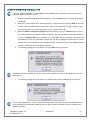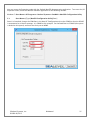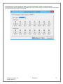
1
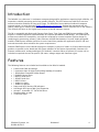
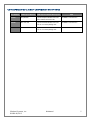
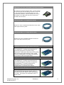
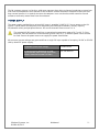
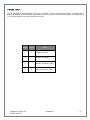
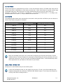
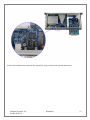
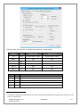
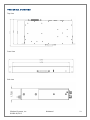
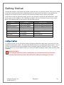
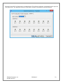
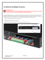
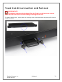
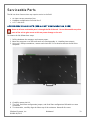
Relio R4 User Manual Item# Relio R4 Sealevel Systems, Inc. Sealevel.com Phone 864.843.4343 Contents Introduction .............................................................................................................................................................. 4 Features ..................................................................................................................................................................... 4 COM Express Module/RAM Configuration options ............................................................................................ 5 Before You Get Started ............................................................................................................................................. 6 What’s Included ..................................................................................................................................................... 6 Advisory Conventions ........................................................................................................................................... 6 Optional Items ....................................................................................................................................................... 7 Specifications .......................................................................................................................................................... 10 Mechanical Dimensions ...................................................................................................................................... 10 Environmental Specifications ............................................................................................................................. 10 Operating Temperature Range........................................................................................................................... 10 Power Supply ....................................................................................................................................................... 11 Power Input.......................................................................................................................................................... 12 System Operation ................................................................................................................................................... 13 Power States ........................................................................................................................................................ 13 High Performance Serial Communication Ports ................................................................................................ 13 CMOS Battery ....................................................................................................................................................... 17 System Description ................................................................................................................................................. 18 Front Panel I/O Connectors ................................................................................................................................ 18 Rear Panel I/O Connectors ................................................................................................................................. 18 Mechanical Drawings .......................................................................................................................................... 19 Getting Started ........................................................................................................................................................ 20 System Startup .................................................................................................................................................... 20 Where to Get Software ........................................................................................................................................ 21 SeaCOM Windows Installation ............................................................................................................................ 22 Upgrading to the current SeaCOM driver .......................................................................................................... 23 ©Sealevel Systems, Inc. SL9260 06/2015 R4 Manual 2 Linux Support ...................................................................................................................................................... 23 SeaMAX ................................................................................................................................................................ 23 Installing SeaRAQ Modules .................................................................................................................................... 31 Fixed Disk Drive Insertion and Removal ............................................................................................................... 32 Serviceable Parts ..................................................................................................................................................... 33 Access Serviceable Parts (Serial Port Configuration, Fuse) .............................................................................. 33 Serial Port 3 Configuration ................................................................................................................................. 34 Input Current Protection Fuse ............................................................................................................................ 34 BIOS Considerations ............................................................................................................................................... 35 Appendix A - Handling Instructions ...................................................................................................................... 36 Appendix B – Electrical Interface ........................................................................................................................... 37 Appendix C – Asynchronous Communications .................................................................................................... 38 Appendix D - General Wiring Guidelines .............................................................................................................. 39 Color Coding Wires ............................................................................................................................................. 39 Wire Routing ........................................................................................................................................................ 39 Grouping Modules............................................................................................................................................... 39 Warranty .................................................................................................................................................................. 40 ©Sealevel Systems, Inc. SL9260 06/2015 R4 Manual 3 Introduction The Relio R4 is a solid-state 1U rackmount computer designed for applications requiring high reliability, I/O expansion, scalable processing and a long product lifecycle. The R4’s fanless and cable-less structure ensures extensive durability for long-term usage. The R4 differs from traditional industrial computer systems in that it is built using the PICMG COM Express architecture. Sealevel has partnered with the leading COM Express module manufacturers to ensure our customers benefit from the best in the industry. This manual will focus on the higher level features of the R4 computer system. The R4 is compatible with Basic and Compact form factor Type 6 pin out COM Express modules. COM Express is a widely supported implementation of Computer on Module (COM) design. The COM Express architecture reduces the complexity, cost and time required for custom computer system design by combining the processing, memory, video, Ethernet and USB functionality in a small, highly-integrated module. COM Express modules install on a carrier board that provides the application specific I/O and external connectors best suited for the system requirements. Sealevel COM Express carrier boards leverage the company’s years as a leader in I/O and communication products to provide carrier board and full system solutions in the fastest time possible. Common I/O features include serial, analog and digital I/O. Sealevel’s extensive library of proven I/O circuits can be included as required to meet the specific I/O count, voltage ranges and connector types. Features The following features are included and installed on the Relio R4 models. Fanless and Cable-less design 2 expansion slots for digital and analog SeaRAQ I/O modules 1 DisplayPort Compatible Video Output 2 Gigabit Ethernet Ports 2 RS-232 Serial Ports 1 RS-485 Serial Port 5 USB 2.0 Ports 1 Audio Line Input 1 Audio Line Output Power and SATA Activity LED Indicators Half-length PCI Express Mini Card Expansion Accepts 1 removable 2.5” SATA Disk Drive Supports Wake-on-LAN 18-36 VDC Input ©Sealevel Systems, Inc. SL9260 06/2015 R4 Manual 4 COM EXPRESS MODULE/RAM CONFIGURATION OPTIONS Part Number COM Express Module R41004 TCA/N2800 Type 6 Compact Module with Intel Atom N2800 Cedarview CPU 4GB DDR3 1333 Non-ECC R43008 IB-i3-3217UE Type 6 Standard Module with Intel Core i3 3217UE Ivy Bridge CPU 8GB DDR3 1333 Non-ECC R47008 IB-i7-3517UE Type 6 Standard Module with Intel Core i7 3517UE Ivy Bridge CPU 8GB DDR3 1333 Non-ECC ©Sealevel Systems, Inc. SL9260 06/2015 COM Express Module Description R4 Manual RAM 5 Before You Get Started WHAT’S INCLUDED The R4 is shipped with the following items. If any of these items are missing or damaged, please contact Sealevel at 864.843.4343 for a replacement. • • R4 Computer System TR144-US AC/DC Power Supply – Desktop 100VAC-240VAC input, 24V 2.7A output w/AC power cable ADVISORY CONVENTIONS Warning - The highest level of importance used to stress a condition where damage could result to the product or the user could suffer serious injury. Important– The middle level of importance used to highlight information that might not seem obvious or a situation that could cause the product to fail. Note – The lowest level of importance used to provide background information, additional tips, or other non-critical facts that will not affect the use of the product. ©Sealevel Systems, Inc. SL9260 06/2015 R4 Manual 6 OPTIONAL ITEMS Depending upon your application, you are likely to find one or more of the following items useful with the R4. All items can be purchased from our website (www.sealevel.com) or by calling our sales team at (864) 843-4343. DB9 Female to DB9 Male Extension Cable, 72” Length (Item# CA127) The CA127 is a standard DB9F to DB9M serial extension cable. Extend a DB9 cable or locate a piece of hardware where it is needed with this six-foot (72-inch) cable. The connectors are pinned one-to-one so the cable is compatible with any device or cable with DB9 connectors. The cable is fully shielded against interference and the connectors are molded to provide strain relief. Dual metal thumbscrews secure the cable connections and prevent accidental disconnection. DB9 Female to DB25 Male Standard RS-232 Modem Cable, 72” Length (Item# CA177) The CA177 is a standard AT-style RS-232 modem cable with a DB9 female connector on one end and a DB25 male connector on the other end. Simply connect the DB9 female connector to the DB9 serial port on the R4, and then connect the DB25 male connector to your RS232 serial modem or other compatible RS-232 serial device. The six foot cable is fully shielded with dual thumbscrews at each connector. The molded connectors integrate strain relief to prevent damage to the cable or connectors. All DB9 modem control signals are implemented and the cable is pinned to EIA-232 standards. Terminal Blocks DB9 Female to 9 Screw Terminal Block (Item# TB05) The TB05 terminal block breaks out a DB9 connector to 9 screw terminals to simplify field wiring of serial connections. It is ideal for RS-422 and RS-485 networks, yet it will work with any DB9 serial connection, including RS-232. The TB05 includes holes for board or panel mounting. The TB05 is designed to connect directly to the R4 DB9 serial ports or any cable with a DB9M connector. ©Sealevel Systems, Inc. SL9260 06/2015 R4 Manual 7 DB9 Female to 5 Screw Terminal Block (RS-485) (Item# TB34) The TB34 terminal block adapter offers a simple solution for connecting RS485 field wiring to the R4’s serial port 3. The terminal block is compatible with 2-wire and 4wire RS485 networks. A pair of thumbscrews secures the adapter to the DB9 male connector and prevents accidental disconnection. CAT5 Patch Cable, 7’ In Length (Part# CA246) Standard 7' CAT5 Unshielded Twisted Ethernet Pair Patch Cable (RJ45) with blue jacket. CAT5 Patch Cable, 10' In Length (Part# CA247) Standard 10’ CAT5 Unshielded Twisted Pair Ethernet Patch Cable (RJ45) with blue jacket. 6 Channel Isolated RTD Analog Inputs (Part# 6511) The SeaRAQ 6511 analog expansion board is specifically designed to interface RTDs (Resistance Temperature Detectors). RTDs offer a wide temperature measurement range, good accuracy, repeatability, and long-term stability well-suited to industrial applications. 6 Channel Isolated Thermocouple Inputs (Part# 6512) The SeaRAQ 6512 analog expansion board is specifically designed to interface inexpensive thermocouples. To simplify temperature calibration in the field, cold junction compensation is provided on the board. 16 Channel Isolated DC Digital Inputs (3-30 VDC) (Part# 8510) The SeaRAQ 8510 expansion board adds 16 channels of isolated digital inputs designed for 3-30 VDC. The inputs are compatible with TTL signal levels. ©Sealevel Systems, Inc. SL9260 06/2015 R4 Manual 8 16 Channel Isolated AC Digital Inputs (0-132 VAC) (Part# 8511) The SeaRAQ 8511 expansion board adds 16 channels of isolated digital inputs rated for 0132 VAC. 16 Isolated Digital Inputs 4 Form C Relay Outputs (Part# 8512) The SeaRAQ 8512 expansion board adds 16 channels of isolated digital inputs rated for 24VDC and 4 Form C Relays. 16 Channel Isolated Relay Outputs (Part# 8520) The SeaRAQ 8520 expansion board adds 16 isolated relay outputs rated for 5-250 VAC and 530 VDC. The Form A relays are organized into four banks of four relays, with each bank sharing a common. The relays support a maximum current load of 2A per relay (4A maximum per bank). The SPST relays are normally open and close when energized. 8 Channel Isolated Relay Outputs (Part# 8521) The SeaRAQ 8521 expansion board adds 8 isolated relay outputs rated for 5-250 VAC and 530 VDC. The Form A relays each have a discrete common and support a maximum 4A current load. The SPST relays are normally open and close when energized. 8 Channel-to-Channel Isolated Analog Inputs (Part# 6510) The SeaRAQ 6510 provides eight general purpose 16-bit A/D channels that can be individually configured for 4-20 mA current loop, 0-5V or 0-10V voltage inputs. 8 Channel-to-Channel Isolated Analog Outputs (Part# 6520) The SeaRAQ 6520 expansion board adds eight 420 mA current loop transmitter outputs and is ideal for interfacing a wide variety of industrial process control and test equipment that use 4-20 mA signaling. ©Sealevel Systems, Inc. SL9260 06/2015 R4 Manual 9 Specifications MECHANICAL DIMENSIONS Depth Width Height 8.00 inches (12.32 cm) 19.00 inches (48.26 cm) 1.75 inches (4.45 cm) ENVIRONMENTAL SPECIFICATIONS Specification Operating Storage 1 Temperature Range -40 to 50 ºC (-40 to 185 ºF) Humidity Range 10 to 90% R.H. Non-Condensing -40 to 85 ºC (-40 to 221 ºF) 10 to 90% R.H. Non-Condensing OPERATING TEMPERATURE RANGE Part Number R41004 COM Express Module TCA/N2800 Operating Temperature Range Comment Requires Industrial Temperature SSD for operating temperatures above 35 °C with no airflow or conduction. 0 - 50 °C -20C to 50 °C optional. Contact Sales R43008 IB-i3-3217UE -40 - 50 °C Requires Industrial Temperature SSD R47008 IB-i7-3517UE -40 - 50 °C Requires Industrial Temperature SSD The R47004 and R47008 can operate with no airflow at 50 °C as long as the steady-state CPU usage does not exceed 50%. If CPU usage is sustained at a workload greater than 50%, the CPU will throttle itself back to keep its internal temperature in a safe range. If the application environment requires the computer to operate at 50 °C with steady state CPU usage greater than 50%, some additional cooling must be used to ensure safe operation of the electronics. 1 Operating temperature is dependent on particular model. See the Operating Temperature Range section for model capabilities. ©Sealevel Systems, Inc. SL9260 06/2015 R4 Manual 10 The R4 computer system is a fan-less, solid-state computer that relies on thermal conduction to move heat from internal components to the outside of the enclosure. Airflow around the computer assists with this heat removal process. It is optimal to mount the computer in an area that has either natural or forced airflow to constantly remove heat from the enclosure. POWER SUPPLY The power supply provided has a universal AC input. It provides 24 VDC @ 2.7 A max output to the R4 system. Typical power consumption varies depending on COM Express Module, memory capacity, OS/software activity and peripheral devices. AC current draw will never exceed 1.4 A. The included AC/DC power supply has an operational temperature range of 0 °C to 40 °C. If the computer must be located in an environment greater than 40 °C, a different power source should be used. Ensure the power source can supply the power listed below. All necessary system voltages are generated from a single DC input capable of accepting 18 VDC to 36 VDC (fed by above DC power supply). Acceptable System Input Voltage 18 VDC-36 VDC DC Current Rating (Dependent on COM Express Module, input voltage, application software load and installed I/O cards) 375 mA-4400 mA ©Sealevel Systems, Inc. SL9260 06/2015 R4 Manual 11 POWER INPUT The R4 is designed to operate from 18 VDC up to 36 VDC. The current draw varies across this range and is heavily dependent on the COM Express module, peripheral devices and installed software. The connector at J12 is Kycon KPJX-4S. Use Kycon SPPX-4P connector. CKT # Signal 1 + Positive DC Power 2 - Negative DC Power 3 - Negative DC Power (GND) 4 + Positive DC Power (GND) ©Sealevel Systems, Inc. SL9260 06/2015 Name R4 Manual 12 System Operation POWER STATES The R4 is designed to operate in 4 Power States as defined by ACPI. S0 – Fully powered and operational S3 – Suspended to memory (known as sleep in Windows) S4 – Suspended to disk (known as Hibernate in Windows) S5 – Powered down in standby (Windows Shutdown) The system can transition from S0 to any of the three listed standby states (S3, S4 or S5) by software command. The system can then be awakened from either listed sleep/standby state by Wake-On-LAN. The system can also be awakened from S3 or S4 with a USB input device such as a HID compliant keyboard or mouse. To be awakened from S3 or S4 with a USB device, the device must be present when the computer enters the sleep state and must remain connected for the duration of the sleep state. These power states are supported by Windows 8.1, Windows 7. HIGH PERFORMANCE SERIAL COMMUNICATION PORTS The R4 provides three high speed serial communication ports supporting data rates up to 921.6 kbps. Ports 1 and 2 are RS-232 serial ports. Port 3 is an RS-485 port for communication with equipment up to 4000 ft. away from the computer or in noisy environments. The RS-485 2-wire mode is optimized for “Multi-Drop” or “Party-line” operations selecting data from multiple peripherals (as many as 32 unit load devices can be connected on an RS-485 bus). In RS-485 mode, our special auto-enable feature allows the RS-485 ports to be viewed by the operating system as a standard COM port. This allows the software application to utilize the serial port for RS-485 communication without the need to control the direction of data between the master and slave device. Our on-board hardware automatically handles the RS-485 driver enable. Features of the serial ports include: • • • • • • • • 16C954 buffered UARTs with 128-byte FIFOs Software configurable clock prescaler and divisor supporting a wide range of baud rates Supports 9-bit protocol framing Each port supports data rates up to 921.6 kbps All modem control signals implemented on RS-232 ports RS-485 line termination, pull-up and pull-down resistors are selectable via dipswitch on Port 3 Automatic RS-485 enable/disable in hardware on Port 3 Uses Sealevel’s SeaCOM enhanced serial driver (Version 3.6.25 or newer) SERIAL PORT SETUP The R4 Serial Ports are assigned I/O addresses and IRQs by the COM Express module BIOS or by a “Plug-nPlay” Operating System. ©Sealevel Systems, Inc. SL9260 06/2015 R4 Manual 13 CLOCK MODES The R4 Serial ports are implemented on a PCIe x1 lane and therefore derive a 62.5MHz clock from the PCI express link which is divided by an 8 bit clock prescaler and a 16 bit clock divisor to provide a wide range of possible baud rates. Note that there are many combinations that can give the same result (e.g. Prescaler=1 and Divisor = 8, Prescaler =2 and Divisor = 4, or Prescaler=8 and Divisor = 1). As long as the calculated data rate is within +/- 2% you should communicate fine. BAUD RATES The following table shows some common data rates with a clock prescaler and divisor you can choose to achieve them when using the R4 computer. For This Data Rate Clock Prescaler Choose This Divisor DLM:DLL 1200 bps 3.625 898 2400 bps 3.625 449 4800 bps 1.875 434 9600 bps 1.875 217 19.2K bps 1.375 148 38.4K bps 1.375 74 57.6K bps 22.625 3 115.2K bps 1 34 230.4K bps 1 17 460.8K bps 2.125 4 921.6K bps 2.125 2 Many non-standard baud rates can be achieved by adjusting the Prescaler and Divisor. Contact Sealevel Systems Technical Support for assistance in determining the correct parameters for your application. Note that if you are using the SeaCOM for Windows driver, it will automatically select these parameters for you based on the baud rate you choose. SERIAL PORT 3 OPERATION Serial port 3 is the RS-485 serial port on the R4 system. For RS-485 half-duplex mode, set the jumper on J4 to pins 2-3 and, in the Device Manager Port Properties Advanced tab, enable the “16950 RS-485 Enable” feature. The lid must be removed to access J4 and SW2 to configure Port 3. ©Sealevel Systems, Inc. SL9260 06/2015 R4 Manual 14 See the Serviceable Parts section of the manual for steps to access the internal electronics. ©Sealevel Systems, Inc. SL9260 06/2015 R4 Manual 15 Typical settings for Serial Port 3 configuration options are shown below: 2 Switch Pin RS485 4 Wire RS485 2 Wire J4 N/A Connect pins 1 and 2 Connect pins 2 and 3 SW2-1 T ON ON SW2-2 PU 2 ON ON 2 2 SW2-3 PD ON ON SW2-4 L OFF ON SW2-5 L OFF ON Switch Name Function 1 2 T PU Adds or removes the 120 ohm termination. Adds or removes pull-up resistor in the RS-485 receiver circuit 3 PD Adds or removes pull-down resistor in the RS-485 receiver circuit 4 L Connects the TX+ to RX+ for RS-485 two-wire operation. 5 L Connects the TX- to RX- for RS-485 two-wire operation. Termination, Pull-Up and Pull-Down may not be necessary depending on the equipment to which the R4 Port 3 is connecting. ©Sealevel Systems, Inc. SL9260 06/2015 R4 Manual 16 CMOS BATTERY The R4 includes a 3V DC type CR2032 battery that supplies the RTC and CMOS memory of the COM Express CPU module. IMPORTANT NOTE: Danger of explosion if battery is incorrectly replaced. Replace only with the same or equivalent type recommended by the manufacturer. Dispose of used batteries according to the manufacturer’s instructions. To fulfill the requirements of EN 60950, the R4 incorporates two current-limiting devices (resistor and diode) in the battery power supply path. ©Sealevel Systems, Inc. SL9260 06/2015 R4 Manual 17 System Description FRONT PANEL I/O CONNECTORS REAR PANEL I/O CONNECTORS ©Sealevel Systems, Inc. SL9260 06/2015 R4 Manual 18 MECHANICAL DRAWINGS Top View Front View Side view ©Sealevel Systems, Inc. SL9260 06/2015 R4 Manual 19 Getting Started The Base R4 computer system does not include a solid state drive or operating system. These can be added at the time of purchase and will be installed by Sealevel’s experienced technicians. If you purchase the computer with a solid state drive, the OS and all necessary software drivers will be preinstalled. If you wish to install the operating system yourself, you will need to install the applicable drivers. Some drivers apply to the hardware on the COM Express module; some are for devices present on the carrier board. The following table lists the devices that will require drivers. Device Location Driver Source Chipset COM Express Module COM Express Module Manufacturer Integrated Graphics COM Express Module COM Express Module Manufacturer Audio Interface COM Express Module COM Express Module Manufacturer Network Connection 1 COM Express Module COM Express Module Manufacturer Network Connection 2 Carrier Board Intel website Serial Ports Carrier Board Sealevel website I2C Bus Carrier Board Sealevel website SYSTEM STARTUP To start the system, be sure that all I/O cards are properly seated then apply power to the system via the supplied external power supply. The system will automatically start up upon application of power. This is a function of the BIOS and the setting should never be changed from the “Power On’ setting. The system does not feature an external power button so it relies on this BIOS setting for proper power up when power is applied. IMPORTANT NOTE: The computer system must be shut down before any I/O expansion cards are inserted or removed. Ensure the front Power LED is OFF before adding or removing any I/O cards. ©Sealevel Systems, Inc. SL9260 06/2015 R4 Manual 20 WHERE TO GET SOFTWARE All Sealevel products are shipped with media containing the installers for each software package available. If the media is otherwise unavailable or if desired, the current versions of Sealevel software packages can be obtained from the Sealevel website (see following instructions). If you already have the Sealevel software, proceed to the Windows or Linux installation section. The following table provides the COM Express module manufacturers for the different models of R4 computers. Model Manufacturer Vendor Website Module Family R410XX R430XX R470XX Congatec ADlink ADlink www.congatec.com www.adlinktech.com www.adlinktech.com Conga-TCA Express-IB Express-IB The network adapter on the carrier board is implemented with an Intel 82574IT NIC on a PCIe x1 lane and provides (1) 10/100/1000Mbps 802.3 compliant Ethernet connection. Install Intel’s “Network Adapter Driver for Windows 7” driver (version 18.4). This can be found at https://downloadcenter.intel.com/ Sealevel software drivers for this computer system can be found at http://www.sealevel.com/support/article/AA-00584. Choose the link for the desired software package and click on the “Download File” link to download the current driver. • • • Install Sealevel’s SeaCOM driver (version 3.6.25 or newer) to use Serial Ports. Install Sealevel’s Talos driver to use I/O Card Sensing, EEPROM, and Backplane Power Control features. Install Sealevel’s SeaMAX software to utilize the I/O Expansion Cards (6510, 8520, etc…) ©Sealevel Systems, Inc. SL9260 06/2015 R4 Manual 21 SEACOM WINDOWS INSTALLATION To install Sealevel software, you must log in as an administrator or otherwise have administrator privileges when the installer is run. 1. When the InstallShield Wizard window appears, click the Next button to initiate the software installation. 2. When the “License Agreement” window appears, accept the terms and click Next to continue. You can click the Print button to print out a copy of the agreement for your records. If you do not accept the terms of the agreement, the installation will stop. 3. When the Ready to Install the Program window appears, click the Install button to install the software onto the hard drive of your computer. The files will be automatically installed into the C:\Program Files or C:\Program Files (x86) folder on your computer. Some versions of Windows will halt the installation and provide you with a dialog box which will ask you for permission for the installer to make changes to your computer. Click on the Allow button to continue installation of your Sealevel software. 4. The following dialog box may appear. Click the OK button to continue. All Sealevel Systems software drivers have been fully tested by Sealevel. Clicking OK will not harm your system. 5. The following dialog box may appear, as shown below. Click the OK button to continue. This is a notification that if you are upgrading from a previous driver version, you should remove the associated Device Manager hardware entries and reinstall the adapter after the installing the SeaCOM software. ©Sealevel Systems, Inc. SL9260 06/2015 R4 Manual 22 6. The setup file will automatically detect the operating environment and install the proper components. Next follow the information presented on the screens that follow. Once the installation is complete, close the disk installation window. 7. Navigate to the Device Manager and remove the Sealevel adapter by right clicking on the line item choosing Uninstall. The adapter is often found under Other devices or under Multiport Serial Adapters as Comm Port Driver for 12000. 8. In the Device Manager under Action, choose Scan for Hardware Changes. This will prompt the installation of the adapter and associate it with the newly installed SeaCOM driver. UPGRADING TO THE CURRENT SEACOM DRIVER 1. Download the current driver using the Instructions from the Where to Get Software section above. Please take note of the destination directory it will save to. 2. Uninstall the currently loaded SeaCOM driver found in the Control Panel. 3. Go through the steps in the SeaCOM Windows Installation section above. LINUX SUPPORT The R4 Serial Ports are supported natively in Linux kernels 2.6.28 and later. SEAMAX Communication with the I/O expansion cards is performed through a single RS-485 two wire serial communication port. Sealevel System’s SeaCOM serial device driver is required for this communication port to operate properly. The I/O subsystem can be accessed via the internal 4th serial port in the system. The Serial Port will enumerate as “12000 RS-485 Two Wire (Port 4)” in device manager. The COM Port is shown as COM6 below. This may not be the case depending on the software configuration of the computer system. Take note of which COM Port the two wire RS-485 is enumerated as in your system. This will be necessary in the following steps. See screenshot below. To access device manager under Windows 7, click on the start menu, right click on “Computer” and select “Properties” from the menu. When the System Control Panel opens click on the “Device Manager” button near the upper left region of the window. To access device manager under Windows 8.X, right click the bottom left corner of the screen and click “Device Manager”. ©Sealevel Systems, Inc. SL9260 06/2015 R4 Manual 23 ©Sealevel Systems, Inc. SL9260 06/2015 R4 Manual 24 You can access the Expansion cards with the Sealevel MaxSSD demonstration application. To access the I/O Expansion cards, launch the MaxSSD software application at the following location. Windows 7: Start Menu>>All Programs>>Sealevel Systems>>SeaMAX>>MaxSSD Configuration Utility 8.X: Start Menu>>[Type:]MaxSSD Configuration Utility[Enter] Once it is launched, change the COM Port in the Host PC Configuration tab to the COM Port that the RS-485 is enumerated as in device manager. It is COM6 in this example. Set the Baud Rate to 230400 (the system is locked to this speed), and leave the Parity set to NONE. ©Sealevel Systems, Inc. SL9260 06/2015 R4 Manual 25 Click on the SeaIO Configuration tab. Change Slave ID to the Slave ID of a slot with an I/O card present. The Slave IDs correlate directly to the slot numbers on the back of the computer system. You can also see which slots have cards plugged in by running the Sample Talos I2C application (See the I2C Devices section of this document). Once a Slave ID is selected, click the “Get SeaIO Module Settings” button and the Module Description section will populate with the device information and you will see a new tab. The type of I/O card that is at the Slave ID you chose will determine the name of this new tab. ©Sealevel Systems, Inc. SL9260 06/2015 R4 Manual 26 If an 8520 card is at the Slave ID you chose, click on the “Digital IO” tab to see the I/O control buttons.Clicking on the pushbuttons will activate the relays. Each relay has a software indicator that shows its current state. Gray is OFF; Green is ON. ©Sealevel Systems, Inc. SL9260 06/2015 R4 Manual 27 You can go back to the SeaIO Configuration tab and select a different slave ID at any time. Controls for the 8521 I/O are shown below. Clicking on pushbuttons will activate the relays. Each relay has a software indicator that shows its current state. Gray is OFF; Green is ON. ©Sealevel Systems, Inc. SL9260 06/2015 R4 Manual 28 Controls for the 8510 I/O indicators are shown below. The software indicators correspond to each input bit; Gray means OFF. The indicators will turn Green when an input is activated by external stimulus. ©Sealevel Systems, Inc. SL9260 06/2015 R4 Manual 29 Controls for the 8511 I/O indicators are shown below. Software indicators correspond to reach input bit; Gray means OFF. The indicators will turn Green when an input is activated by external stimulus. ©Sealevel Systems, Inc. SL9260 06/2015 R4 Manual 30 Installing SeaRAQ Modules IMPORTANT NOTE: The computer system must be shut down before any I/O expansion cards are inserted or removed. Ensure the front Power LED is OFF before adding or removing any I/O cards. Installing SeaRAQ modules is a simple matter of selecting a slot on the rear of the unit then removing the blank plate of the slot that you want to insert the module. Slide the card down the card guide and then seat into the connector in the rear of the slot, then tighten the thumbscrews into the chassis. 1. Loosen screws to the blank plate to remove it. 2. Slide card down guide rails into socket. 3. Tighten screws on left and right of bracket to securely mount the card. ©Sealevel Systems, Inc. SL9260 06/2015 R4 Manual 31 Fixed Disk Drive Insertion and Removal IMPORTANT NOTE: The computer system must be shut down before the disk drive can be inserted or removed. Ensure the front Power LED is OFF before adding or removing the disk drive. To remove the disk drive, simply rotate the retaining screws counterclockwise and gently pull the drive handle to remove. ©Sealevel Systems, Inc. SL9260 06/2015 R4 Manual 32 Serviceable Parts The R4 has three features that may require service in the field: • • • An input current protection fuse Hardware configuration for Serial Port 3 A 2.5” disk drive ACCESS SERVICEABLE PARTS (SERIAL PORT CONFIGURATION, FUSE) Access to all user-serviceable parts is through the lid of the unit. Do not disassemble any other parts of the unit to gain access as this may cause damage to the unit. To remove the lid, follow these steps. 1. Safely shutdown the computer and remove power. 2. Move the computer to an ESD safe work area (See Appendix A – Handling Instructions). 3. Using a #1 Phillips screwdriver, remove and retain the 22 Flat head screws on the lid of the computer. 4. Carefully remove the lid. 5. The Fuse, Serial Port configuration jumper, and Serial Port configuration DIP switch are now accessible. 6. To reassemble, carefully align the lid on top of the enclosure. Reinstall all screws. ©Sealevel Systems, Inc. SL9260 06/2015 R4 Manual 33 For optimal reliability, apply a small amount of Loctite 242 Medium Strength threadlocker to the threads of each screw. Torque screws between 3 in-lb. and 5 in-lb. SERIAL PORT 3 CONFIGURATION Serial Port 3 is configured as RS485 Half Duplex (2-Wire). Configuration features are found on the 12001 carrier board near the protection fuse via SW2 and J4. See the Serial Port 3 Operation section for detailed configuration options. INPUT CURRENT PROTECTION FUSE The fuse holder located at location F2 is located on the positive power input path of the 12001 carrier board. To protect the user and the computer system from major system faults, the system is designed to have the fuse fail if DC current of 10A or greater is present. The R4 uses an automotive style Mini-Blade Fuse (Littelfuse PN 0997010.WXN). To replace the fuse: 1. Follow the steps found in the Access Serviceable Parts section above to access the fuse. 2. Once exposed, grip the fuse and wiggle it back and forth while pulling up until the fuse slides out of the holder. 3. Place the blades of the new fuse in the holder and press it straight down into the holder until the blades are completely hidden by the fuse holder contacts. ©Sealevel Systems, Inc. SL9260 06/2015 R4 Manual 34 BIOS Considerations The BIOS functions, features and settings are fully contained on the COM Express module. Refer to the COM Express module manufacturer’s website for detailed BIOS settings. A few settings are generally present among COM Express Modules that can affect functionality. • COM Express Type 6 modules have DDIs (Digital Display Interfaces) that can be implemented as DisplayPort, HDMI or DVI interfaces. The R4 carrier board implements DisplayPort only. Ensure DDI1 is set to DisplayPort interface in the BIOS. Some Passive DisplayPort to DVI adapters have been found which require DDI1 to be set to HDMI/DVI with the R41004 BIOS. This is the exception, not normal behavior. If DDI1 is inadvertently set to HDMI/DVI video will not work on native DisplayPort monitors or most DisplayPort to HDMI/DVI/VGA adapters. If this happens, the computer must be booted and the BIOS must be entered “blindly” to restore the computer to a usable state. For example, take these steps to recover an R41004 (Conga-TCA family module) from this state. 1. Attach a USB keyboard to the computer. 2. Apply power and immediately and repeatedly press the delete key for 15 seconds. This will ensure the computer has had time to boot and enter the BIOS. 3. Press the F9 key to load optimal defaults then press enter to validate the change. 4. Press the following key pattern: • Right arrow, • Enter • Down arrow 9 times • Enter • Up arrow • Enter • F10 • Enter 5. If performed properly, the DDI1 setting will have been restored to DisplayPort, the BIOS settings were saved to flash memory, and the computer was rebooted. The display should now be working. If this does not work, contact Sealevel Systems Technical support. “PowerOn after PWR Failure” is a setting present in most BIOS. This setting determines if the computer boots when power is applied. R4 computers are shipped with this set to always power on; however, “Remain Off” and “Last State” should never be used. Saving either setting will leave the computer in a powered down state that cannot be recovered from without removing the lid due to the intentional absence of a power button. ©Sealevel Systems, Inc. SL9260 06/2015 R4 Manual 35 Appendix A - Handling Instructions ESD Warnings Electrostatic Discharges (ESD) A sudden electrostatic discharge can destroy sensitive components. Proper packaging and grounding rules must therefore be observed. Always take the following precautions: • Transport boards and cards in electrostatically secure containers or bags. • Keep electrostatically sensitive components in their containers, until they arrive at an electrostatically protected workplace. • Only touch electrostatically sensitive components when you are properly grounded. • Store electrostatically sensitive components in protective packaging or on anti-static mats. Grounding Methods The following measures help to avoid electrostatic damages to the device: • Cover workstations with approved antistatic material. Always wear a wrist strap connected to a properly grounded workplace. • Use antistatic mats, heel straps, and/or air ionizers for more protection. • Always handle electrostatically sensitive components by their edge or by their casing. • Avoid contact with pins, leads, or circuitry. • Turn off power and input signals before inserting and removing connectors or connecting test equipment. • Keep work area free of non-conductive materials such as ordinary plastic assembly aids and Styrofoam. • Use field service tools such as cutters, screwdrivers, and vacuum cleaners that are conductive. ©Sealevel Systems, Inc. SL9260 06/2015 R4 Manual 36 Appendix B – Electrical Interface RS-232 Quite possibly the most widely used communication standard is RS-232. This implementation has been defined and revised several times and is often referred to as RS-232 or EIA/TIA-232. The IBM PC computer defined the RS-232 port on a 9-pin D-sub connector, and subsequently, the EIA/TIA approved this implementation as the EIA/TIA-574 standard. This standard is defined as the 9-Position Non-Synchronous Interface between Data Terminal Equipment and Data Circuit-Terminating Equipment Employing Serial Binary Data Interchange. Both implementations are in widespread use and are referred to as RS-232 in this document. The RS-232 standard defines operations at data rates up to 20K bps at distances less than 50 ft. The absolute maximum data rate may vary due to line conditions and cable lengths. RS-232 is a singleended or unbalanced interface, meaning that a single electrical signal is compared to a common signal (ground) to determine binary logic states. The RS-232 and the EIA/TIA-574 specification define two types of interface circuits: Data Terminal Equipment (DTE) and Data Circuit-Terminating Equipment (DCE). RS-485 RS-485 is backwardly compatible with RS-422; however, it is optimized for partyline or multi-drop applications. The output of the RS-485 driver is capable of being Active (enabled) or Tri-State (disabled). This capability allows multiple ports to be connected in a multi-drop bus and selectively polled. RS-485 allows cable lengths up to 4000 feet and data rates up to 10 Megabits per second. The signal levels for RS485 are the same as those defined by RS-422. RS-485 has electrical characteristics that allow for 32 drivers and 32 receivers to be connected to one line. This interface is ideal for multi-drop or network environments. RS-485 tri-state driver (not dual-state) will allow the electrical presence of the driver to be removed from the line. Only one driver may be active at a time and the other driver(s) must be tri-stated. RS-485 can be cabled in two ways, two wire and four wire mode. Two wire mode does not allow for full duplex communication, requiring that data be transferred in only one direction at a time. For half-duplex operation, the two transmit pins should be connected to the two receive pins (Tx+ to Rx+ and Tx- to Rx-). Four wire mode allows full duplex data transfers. RS-485 does not define a connector pin-out or a set of modem control signals. RS-485 does not define a physical connector. ©Sealevel Systems, Inc. SL9260 06/2015 R4 Manual 37 Appendix C – Asynchronous Communications Serial data communications implies that individual bits of a character are transmitted consecutively to a receiver that assembles the bits back into a character. Data rate, error checking, handshaking, and character framing (start/stop bits) are pre-defined and must correspond at both the transmitting and receiving ends. Asynchronous communications are the standard means of serial data communication for PC compatible and PS/2 computers. The original PC was equipped with a communication or COM port that was designed around an 8250 Universal Asynchronous Receiver Transmitter (UART). This device allows asynchronous serial data to be transferred through a simple and straightforward programming interface. A starting bit followed by a pre-defined number of data bits (5, 6, 7, or 8) defines character boundaries for asynchronous communications. The end of the character is defined by the transmission of a pre-defined number of stop bits (usually 1, 1.5 or 2). An extra bit used for error detection is often appended before the stop bits. The diagram below demonstrates asynchronous communication bits. This special bit is called the parity bit. Parity is a simple method of determining if a data bit has been lost or corrupted during transmission. There are several methods for implementing a parity check to guard against data corruption. Common methods are called (E)ven Parity or (O)dd Parity. Sometimes parity is not used to detect errors on the data stream. This is referred to as (N)o parity. Because each bit in asynchronous communications is sent consecutively, it is easy to generalize asynchronous communications by stating that each character is wrapped (framed) by pre-defined bits to mark the beginning and end of the serial transmission of the character. The data rate and communication parameters for asynchronous communications have to be the same at both the transmitting and receiving ends. The communication parameters are baud rate, parity, number of data bits per character, and stop bits (i.e., 9600,N,8,1). ©Sealevel Systems, Inc. SL9260 06/2015 R4 Manual 38 Appendix D - General Wiring Guidelines In addition to the following wiring suggestions, we strongly urge that you follow all wiring and safety codes that apply to your area or your type of equipment. In the United States, most areas have adopted the National Electrical Code standard and specify that all wiring conform to its requirements. In other countries, different codes will apply. For maximum safety to personnel and property, you must follow these codes. Failure to do so can lead to personal injury, death, property damage, or property destruction. COLOR CODING WIRES The following color codes are commonly used in industrial equipment manufactured in the United States. They are listed here as a reference. Where they are in conflict with codes that apply to your area or your type of equipment, you should follow your applicable codes instead. Besides satisfying code requirements, wire color-coding makes testing and troubleshooting safer, faster, and easier. Green or green with stripe– Ground Black – Primary AC Red – Secondary AC Blue – DC White – Common or neutral Yellow – Secondary power source not controlled by the main disconnect. Alerts maintenance personnel that there may be power present (from an external source) even if the equipment is disconnected from its main power source. WIRE ROUTING To reduce noise coupling from external sources, it is recommended you keep electrically noisy wiring, such as AC power wiring and Discrete Output Module wiring, physically separated from low-level signal wiring such as DC and Analog Input module wiring or communications cables. This can be accomplished by grouping separately, where practical, the following categories of wiring: Analog Input or Output Module wiring. This wiring should be shielded to further reduce noise coupling. Communications Cables. Wiring such as Ethernet, USB, or serial communications cables should be kept away from noise-producing wiring. DC Input Module wiring. Although suppressed internally, these low-level inputs should be further protected against noise coupling by observing these wiring practices. Discrete Output Module wiring. These often switch inductive loads that produce noise spikes when switched off. Where AC or Output wiring bundles must pass near noise-sensitive signal wiring bundles, avoid running them parallel with each other. Route them so that, if they have to cross, they do so at a right angle. This will minimize possible coupling between them. GROUPING MODULES If practical, grouping similar modules together can help keep wiring segregated. For example, the left end of a unit could contain Analog modules, the middle could contain DC modules, and the right end could contain AC modules. ©Sealevel Systems, Inc. SL9260 06/2015 R4 Manual 39 Warranty Sealevel's commitment to providing the best I/O solutions is reflected in the Lifetime Warranty that is standard on all Sealevel manufactured I/O products. Relio™ industrial computers are warranted for a period of two years and the R9 family is warranted for a five year period from date of purchase. We are able to offer this warranty due to our control of manufacturing quality and the historically high reliability of our products in the field. Sealevel products are designed and manufactured at its Liberty, South Carolina facility, allowing direct control over product development, production, burn-in and testing. Sealevel achieved ISO-9001:2008 certification in 2011. Warranty Policy Sealevel Systems, Inc. (hereafter "Sealevel") warrants that the Product shall conform to and perform in accordance with published technical specifications and shall be free of defects in materials and workmanship for the warranty period. In the event of failure, Sealevel will repair or replace the product at Sealevel's sole discretion. Failures resulting from misapplication or misuse of the Product, failure to adhere to any specifications or instructions, or failure resulting from neglect, abuse, accidents, or acts of nature are not covered under this warranty. Warranty service may be obtained by delivering the Product to Sealevel and providing proof of purchase. Customer agrees to insure the Product or assume the risk of loss or damage in transit, to prepay shipping charges to Sealevel, and to use the original shipping container or equivalent. Warranty is valid only for original purchaser and is not transferable. This warranty applies to Sealevel manufactured Product. Product purchased through Sealevel but manufactured by a third party will retain the original manufacturer's warranty. Non-Warranty Repair/Retest Products returned due to damage or misuse and Products retested with no problem found are subject to repair/retest charges. A purchase order or credit card number and authorization must be provided in order to obtain an RMA (Return Merchandise Authorization) number prior to returning Product. How to obtain an RMA (Return Merchandise Authorization) If you need to return a product for warranty or non-warranty repair, you must first obtain an RMA number. Please contact Sealevel Systems, Inc. Technical Support for assistance: Available Phone Email Monday – Friday, 8:00AM to 5:00PM EST 864-843-4343 [email protected] Trademarks Sealevel Systems, Incorporated acknowledges that all trademarks referenced in this manual are the service mark, trademark, or registered trademark of the respective company. ©Sealevel Systems, Inc. SL9260 06/2015 R4 Manual 40