1
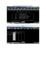
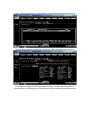
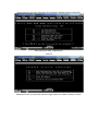
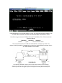
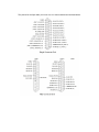
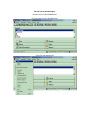
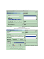
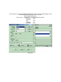
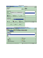
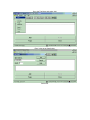
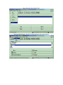
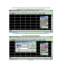
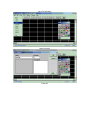
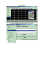
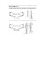
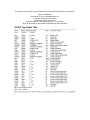
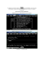
Purpose:
To establish communication between a QuickPanel and a IC693CMM311. We will be using
QuickDesigner to program the panel and LogicMaster90 to setup the PLC Hardware
Configuration.
We will first start with LogicMaster90.
Double click on you C:\LM90\LM90.bat to open the program.
Press F2 to go into your Logicmaster 90 Configuration Package
In this example we are using a program called CMM2QP. Please key in the name of our folder
and press “Y” to create the folder.
We are now in the Logicmaster 90 Configuration Package.
Please press F1 to enter the I/O configuration.
Use your arrow key to navigate to an empty slot and press F6 to insert a communications
module.
Press F3 for Serial and select the IC693CMM311 Communications Coprocessor from the list.
Once the module has been inserted there should be a CMM configuration screen come up.
The items to note on the configuration include: The Config Mode that is highlighted (by pressing
the Tab key it will toggle different communications settings. The Data Rate, Parity and Flow
Control are also to be noted (they are to be matched to what the QuickPanel serial settings are).
Please back out to the main Logicmaster 90 Configuration Package screen by hitting Esc.
Press F9 to go to Utility: Load/Store/etc.
Press F2
Hold down the ALT key and press letter M to toggle modes from Offline to Monitor to Online.
Press ENTER key to store.
In this example we do not need to program any logic. We will be using a System register in the
PLC that is there by default at all times and constantly toggles a bit between 1 and 0.
We will be using as outlined in GFK0467 Series 90™-30/20/Micro PLC CPU Instruction Set
Reference Manual
Reference
Nickname
Definition
%S0005
T_SEC
1.0 second timer contact.
The recommended setup to a CMM with the QuickPanel is using a Wye cable. The
purpose of the Wye cable is to separate the two ports from a single physical connector (that is,
the cable separates out the signals).
As outlined in GFK0582 Series 90 PLC Serial Communications User’s Manual
The RS-485 signals for port 2 and the RS-232 signals for port 1 are assigned to the standard
connector pins. The RS-232 signals for port 2 are assigned to normally unused connector pins.
The pinouts for the Wye cable (IC693CBL305) have been extracted and are listed below.
We will look at QuickDesigner.
Double click on C;\Quick\QMGR.exe.
From the main screen in QuickDesigner:
Go to File and choose New.
Name the Project and select the type of Display Device.
Select the OK button.
Use the dropdown list to select the GE SNP driver.
Click on the Port button.
In this example we are using the HMI-CAB-C93 RS485 cable to connect a target display to a GE
90-30 CMM Module RS485 port 2 on the wye cable.
Recommended settings are:
Elect. Format RS422/485 Full Duplex (HMI-CAB-C93 Cable)
Baud Rate
19200
Data Bits
8
Parity
Odd
Stop Bits
1
Handshake
None
Select OK.
Select the Protocol button.
For GE SNP (point to point), no CPI ID needs to be entered. Time Out and Start Time defaults
should be fine. Please make certain that the Processor Type is set to X31/X32 for the Series 9030.
Select OK.
Select OK again.
Go to the Components Menu and select Tags.
Go to the Tag Menu and select Add.
Enter in the tag as listed below.
Select OK.
Go to Tag menu then choose Close.
From the Quick Manager, Go tot the Components Menu then choose panels.
Left click the tool resembling the Light bulb. This is the Pilot Light. Please note that the
description for each tool is displayed in the bottom left corner.
Then left click once on the drawing area where you are wanting to place the tool.
Select the tag from the tag dropdown list.
Select OK.
Go to File and Save.
Name the panel.
Press OK.
Go to File and Exit.
From the Quick Manager go to the Project Menu and Select Download.
The possible communication cables for communications to a IC693CMM311 are as follows:
The last item of note is the tag nomenclature on the QuickPanel required for communication.
Format: Gnfffaaa:bb
The leading 'G' may be substituted with a '%'
n is the memory type of the variable
fff is the data type of the variable
aaa is the address of the variable (range 1--??? Decimal)
:bb is the bit number of the variable (supported only where specified)