1
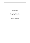
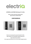
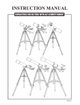
User's manual for RF-MFX600-X series smart self-adaption module For RF-MFX600-F, RF-MFX600-J, RF-MFX600-H. The system uses the smart self-adaption FHSS algorithm, it can automaticly select free frequency when power on; If there is periodic interference or channel jams beyond the set time, it will automatically update the hopping frequency group, this insures the stability to the hilt; Our own unique features are as following: 1、 The bind switch designed in anti-collision, which can prevent operating error; 2、 There are five programming switches to set various functions of Mi and Mx series receiver; 3、 The ESC type of Mi and Mx series receiver can be programmed; 4、 The internal linear servo controlled channels of Mx series receiver can be programmed; 5、 The output channel of Mi and Mx series receiver can be programmed. A、Product specification Type RF-MFX600-F RF-MFX600-J RF-MFX600-H Size/mm 58.15x37.26x22.05 64.46x51.80x23.27 58.15x37.26x22.05 Weight 42.5g 49.3g 42.5g Maximum transmission power 18DBm 18DBm 18DBm Band 2.4G 2.4G 2.4G Voltage Range 5.0~12.0V 5.0~12.0V 5.0~12.0V Signal Type PPM(50mV 或 2~5V) PPM(50mV 或 2~5V) PPM(50mV 或 2~5V) Support the external signal Yes Yes Yes Applicable Transmitter FUTABA,SPEKTRUM JR,SPEKTRUM HITEC,SPEKTRUM NOTE: 1) For FUTABA, JR and HITEC transmitter, those suitable for module can be supported; 2) Besides DX6i and DX7, other types haven’t been tested. B、Instructions 1、Programming function: Please refer to the instructions of Mi, Mx series receiver. 2、Port distribution: CON3 CON1 CON2 CON1 CON2 3、How to connect with FUTABA, JR or HITEC transmitter: RF-MFX600-F/J/H can be installed directly to the position where original module was installed of FUTABA, JR and HITEC transmitter. Usage: 1) Turn on the power of transmitter, then set to PPM mode, and turn off the power; 2) Take down the original module, install RF-MFX600-F/J/H, then load antenna, ensure tightening the antenna; 3) Set SW5 on the RF-MFX600-F/J/H to OFF, and then turn on the power of transmitter. If the red LED on the module flashes, it shows that RF-MFX600-F/J/H has detected the PPM signal of the transmitter. 4、How to connect with SPEKTRUM transmitter: RF-MFX600-F/J/H connects with SPEKTRUM transmitter wirelessly through SPEKTRUM’S SPM9545. Usage: 1) Choose one SPM9545 which has been bounded with SPEKTRUM transmitter; 2) Connect SPM9545 to CON3 on the RF-MFX600-F/J/H according to figure 1, then fix SPM9545 according to figure 2, and turn SW5 on RF-MFX600-F/J/H to ON; 3) Firstly turn on the SPEKTRUM transmitter power, and then connect the battery with CON1 on RF-MFX600-F/J/H; 4) If the red LED on RF-MFX600-F/J/H flashes, it shows RF-MFX600-F/J/H and SPEKTRUM transmitter connected successfully. 5、Power ON and Power OFF order: Power ON: Use in FUTABA, JR or HITEC transmitter: Transmitter Receiver, Use in SPEKTRUM transmitter: Transmitter Module Receiver; Power OFF: Use in FUTABA, JR or HITEC transmitter: Receiver Transmitter, Use in SPEKTRUM transmitter: Receiver Module Transmitter. 6、Binding: RF-MFX600-F/J/H can be bounded with a receiver or more at a time; When RF-MFX600-F/J/H connects with FUTABA, JR or HITEC transmitter.SW1~SW5 are set to OFF after bounded, the green LED often goes out when power is on; When RF-MFX600-F/J/H connects with SPEKTRUM transmitter, SW1~SW4 are set to OFF after bounded, the green LED is bright when power is on. 1) First power on the receiver, after about 5s, the receiver come into binding mode (LED turns from slow flash to skip flash); 2) Power on the transmitter, press the bind switch on the module (first set the program switch if needed), when the green LED turns from dark to bright, then from bright to dark, loosen the bind switch, then module comes into binding mode, and the red LED on the module turns to fast flash; 3) In about 3s, the LED on the receiver turns from skip flash to slow flash, then to constant lighting; 4) If the transmitter can operate the receiver, then it succeeds. NOTE: Must be bind in the first time. Warning: * Prohibit Binding operation when operating the model; * Prohibit using these products in the high temperature and high humidity environment; * Please notice the place of anode and cathode when pit in the batteries; * Non-normal use damage is not responsible for warranty. Mx series RX user's manual For Mx-0104ARX-HBL, Mx-0104ARX-H, Mx-0104ARX-LBL, Mx-0104ARX-L, Mx-0104ARX-LS. Mx series products are a group of programmable receiver that integrates brush ESC (or brushless ESC) and two linear servos, through elaborate design, it has tiny volume and very light weight, applicable to micro airplanes in any shape; This series receiver includes type H and L, type H is a little wider, applicable to various micro 3D airplane, park airplane and indoor airplane, it can be used on micro triangle airplane through programming, type L is slender, however small your lover is, it can be matched perfectly; To make you use it more conveniently, the ESC type, linear servo control channels and output channels on the receiver can be programmed easily. A、Product specification Type Mx-0104ARX-HBL Mx-0104ARX-H Mx-0104ARX-LBL Mx-0104ARX-L Mx-0104ARX-LS Number of channels 5CH 5CH 5CH 5CH 3CH Band 2.4G 2.4G 2.4G 2.4G 2.4G Internal ESC 3.5A Brushed ESC 2A Brushed ESC 3.5A BL ESC 2A Brushed ESC 2A Brushed ESC External ESC Unsupported Support Unsupported Support Support Servo travelling range 8mm 8mm 8mm 8mm 8mm Servo speed 0.12s/4.2V 0.12s/4.2V 0.12s/4.2V 0.12s/4.2V 0.12s/4.2V Torque 35g/4.2V 35g/4.2V 35g/4.2V 35g/4.2V 35g/4.2V Voltage Range 3.0V~4.2V 3.0V~4.2V 3.0V~4.2V 3.0V~4.2V 3.0V~4.2V Size / mm 32.6x24.5x7.8 25.0x24.5x7.8 55.0x18.1x7.8 45.0x18.1x7.8 45.0x13.0x7.8 Weight 3.1g 2.8g 2.9g 2.7g 2.5g Antenna Length 30mm 30mm 30mm 30mm 30mm Programming function B、C、D、E A、B、C、D、E B、C、D、E A、B、C、D、E A、B、C Note: Please refer to “Programming function” for the instruction of programming function. B、Instructions 1、Connect the motor: Mx-0104ARX-HBL, Mx-0104ARX-LBL have internal 3.5A ESC for brushless motor, brushless motor directly connect to the CON1; Mx-0104ARX-H, Mx-0104ARX-L, Mx-0104ARX-LS have internal 2A brush ESC, and support external ESC; When connecting a brush motor, before binding, you need to set the SW1 on the module to ON; for the external ESC, you need to set the SW1 on the module to OFF; When using internal ESC for brush motor, it’s in locked state after powered for security reasons, Only when pushing the throttle stick to its lowest setting (Enable the throttle reverse function, and set the throttle trim switch to the lowest), and stay about 1 second, when LED on the receiver is in dark for 1s, it shows it has been unlocked, then you can control it; Please see the addendum for the wiring diagram for brush motor and brushless motor. 2、Connecting the servo: This series receiver contains two digital linear servos, if you need external servo (unsuitable for Mx-0104ARX-LS), we recommend that you use digital linear servo Mi-LSM1300; If you want know mort, please sign in Http: //www.origin-kk.com. 3、Low voltage detection: The low voltage alarm value of this series of receiver is set to 2.8V, when the battery voltage is lower than 2.8 V, LED on the receiver will flash and the power halved, but servos can be controlled. 4、States description for LED: Constant lighting: the receiver has received signal; Slow flash: the receiver hasn’t received signal; Fast flash: Hardware malfunction or low voltage warning; Skip flash: the receiver has come into binding mode. 5、Programming function: In order to let you use this series receiver more flexible and convenient, we develop five programming functions for it. These five ones are simple, you only need to set up the right switch on the module according to the required functions, then go on with the binding operation, when this done, the programming operation is completed, too. If you want to change the programming content, just reset the switch. Programming function A: choose the ESC type. SW1 ON: Internal brush ESC; SW1 OFF: Internal brushless ESC, or external ESC. Programming function B: Rudder and aileron channel exchange, this make Type H can apply to micro triangle airplane. SW2 ON:Exchange; SW2 OFF:No exchange. Programming function C: exchange servo A and servo B, this is to correct the connection error of the rudder and the elevator, or the aileron and the elevator to the receiver. SW3 ON:Exchange; SW3 OFF:No exchange. Programming function D: CON3 output channel selection. SW4 ON: Output fifth channel; SW4 OFF: Output fourth channel. Programming function E: movement direction selection on CON2 and CON3 (only for Output fourth channel of CON3), this function is important to applying two linear servo model airplane on aileron. SW5 ON: Reverse motion; SW5 OFF: Coincidental motion. NOTE: * Mx-0104ARX-LS doesn’t support programming project D and E; * Please see the addendum for the distribution of CON1, CON2, CON3, CON4 on the receiver; * SW1~SW5 are the switches for module. 6、Binding: 1) First power on the receiver, after about 5s, the receiver come into binding mode (LED turns from slow flash to skip flash); 2) Power on the transmitter, press the bind switch on the module(first set the program switch if needed),when the green LED turns from dark to bright, then from bright to dark, loosen the bind switch, then module comes into binding mode, and the red LED on the module turns to fast flash; 3) In about 3s,the LED on the receiver turns from skip flash to slow flash, then to constant lighting; 4) If the transmitter can operate the receiver, then it succeeds. NOTE: Must be bind in the first time. Warning: * Prohibit changing the type of ESC when the motor is connected; * Prohibit connecting a brush motor when it is ESC for brushless motor; * Prohibit putting it on metal surface when power is on; * Prohibit using these products in the high temperature and high humidity environment; * Please notice the place of anode and cathode when pit in the batteries; * Non-normal use damage is not responsible for warranty. Addendum: Mi series RX user's manual For Mi-0103MRX, Mi-0103MRX-S, Mi-0104ARX, Mi-0104ARX-S, Mi-0006BRX. Mi series products are a group of super tiny receiver that integrates ESC for brush motor. They have small volume, light weight, and can be the best partner of micro-airplane; Mi series receiver includes standard servo type and magnetic actuator servo type; the former is applicable to micro-airplane whose weight within 15~200 grams; the latter is applicable to the weight within 15grams; To make the receiver convenient to install, we keep a no components area in two models, you can use a small piece of double-sided adhesive to fix it in your machine. A、Product specification Type MI-0103MRX MI-0103MRX-S MI-0104ARX MI-0104ARX-S MI-0006BRX Number of channels 3CH 3CH 4CH 4CH 6CH Band 2.4G 2.4G 2.4G 2.4G 2.4G Internal ESC 2A Brushed ESC 2A Brushed ESC 2A Brushed ESC 2A Brushed ESC None External ESC Supported Supported Supported Supported Supported Supported servo type magnetic actuator magnetic actuator Standard standard standard JST type 1.25mm JST 1.25mm JST 1mm JST 1mm JST 1.25mm JST Recommended fixed way none double-sided adhesive none double-sided adhesive none Voltage Range 3.0V~4.2V 3.0V~4.2V 3.0V~5.0V 3.0V~5.0V 3.0V~5.0V Size / mm 20.50x11.0x3.7 20.0x12.0x3.6 18.8x11.0x6.4 21.4x12.0x6.0 Weight 1.0g 0.65g 1.0g 0.8g 1.6g Antenna Length 56mm 30mm 56mm 30mm 30mm Programming function A A, B, C A A, B, C, E none NOTE: Please refer to “Programming function” for the instruction of programming function. B、Instructions 1、Connect the motor: Mi-0103MRX, Mi-0103MRX-S, Mi-0104ARX, Mi-0104ARX-S have internal 2A ESC for brush motor, and support external ESC; When connecting a brush motor, before binding, you need to set the SW1 on the module to ON; for the external ESC, you need to set the SW1 on the module to OFF; When using internal ESC for brush motor, it’s in locked state after powered for security reasons, Only when pushing the throttle stick to its lowest setting (Enable the throttle reverse function, and set the throttle trim switch to the lowest), and stay about 1 second, when LED on the receiver is in dark for 1s, it shows it has been unlocked, then you can control it; Please see the addendum for the wiring diagram for brush and brushless motor (Brush motor on the Mi-0104ARX-S is welded on the opposite pad of the receiver). 2、Connecting the servo: Mi-0103MRX, Mi-0103MRX-S are magnetic actuator servo type receiver, please see the addendum for the wiring diagram; Mi-0104ARX, Mi-0104ARX-S are standard servo type receiver, We recommend that you use digital linear servo Mi-LSM1300; If you want know mort, please sign in Http: //www.origin-kk.com. 3、Low voltage detection: The low voltage alarm value of this series of receiver is set to 2.8 V, when the battery voltage is lower than 2.8 V, LED on the receiver will flash and the power halved, but servos can be controlled. 4、States description for LED: Constant lighting: the receiver has received signal; Slow flash: the receiver hasn’t received signal; Fast flash: Hardware malfunction or low voltage warning; Skip flash: the receiver has come into binding mode. 5、Programming function: In order to let you use this series receiver more flexible and conveniently, we develop four programming functions for it. These four ones are simple, you only need to set up the right switch on the module according to the required functions, then go on with the binding operation, when this done, the programming operation is completed, too. If you want to change the programming content, just reset the switch. Programming project A: choose the ESC type. SW1 ON: Internal brush ESC; SW1 OFF: External ESC. Programming project B: rudder and aileron exchange. SW2 ON: Exchange; SW2 OFF: No exchange. Programming project C: exchange servo A and servo B, this is to correct the connection error of the rudder and the elevator, or the aileron and the elevator to the receiver. SW3 ON: Exchange; SW3 OFF: No exchange. Programming project E: “Mul-CH” agreement selection, this function is for using the multi-axial digital linear servo Mi-LSM2400 on Mi-010ARX-S, and make CON3 and CON4 output opposite-direction aileron or rudder signals. SW5 ON: Open “Mul-CH”agreement; SW5 OFF: Close “Mul-CH”agreement. NOTE: * Please see the addendum for the distribution of CON1, CON2, CON3, CON4 on the receiver; * SW1~SW5 are the switches for module. 6、Binding: 1) First power on the receiver, after about 5s, the receiver come into binding mode (LED turns from slow flash to skip flash); 2) Power on the transmitter, press the bind switch on the module(first set the program switch if needed), when the green LED turns from dark to bright, then from bright to dark, loosen the bind switch, then module comes into binding mode, and the red LED on the module turns to fast flash; 3) In about 3s, the LED on the receiver turns from skip flash to slow flash, then to constant lighting; 4) If the transmitter can operate the receiver, then it succeeds. NOTE: Must be bind in the first time. 7、FQA: a)、Why keep a blank area (White lines on the back part) on Mi-0103MRX-S and Mi-0104ARX-S? Will it add the weight? Answer: Weight is very important for micro-airplane. If we can make the plane reduce a little weight, even 0.1g, we will insist on it. Through long-term exchange with numerous micro-airplane enthusiasts, we find it can bring some complicated negative impacts such as increased weight and disassembling trivial if wrongly fixing the receiver. Safe, convenient fixed way can bring many advantages to the design, production, flight and maintenance of micro-airplane. After repeated experiments, we find that double-sided adhesive tape is the best for fixing, so, when designing these two receivers, we retain a blank area specially (White lines on the back part). Whichever your lover is micro-KT airplane, micro-pellicle airplane, or micro-emulation airplane, just keep a small piece of space on the proper position of airplane, you can fix the receiver securely with a small piece of double-sided adhesive. The blank areas on the receiver seemingly will add a bit of weight, but in fact will reduction more. b)、Why use 1mm JST on Mi-0104ARX,Mi-0104ARX-S? Answer: When assembling and micro-airplane, replacing electronic equipment is unavoidable, while micro-airplane has intensity difference, and the space is little, it’s easy to break it. 1.25mm JST on general micro receiver needs more efforts to insert or remove, while you just need a perturbation son to insert or remove 1mm JST, and when its plug and socket installed properly, it’s very stable. With precise measurement, the strength for inserting and removing 1mm JST are 4.1N and 3.8N, while 1.25mm JST needs 9.4N and 9.6N. Warning: * Prohibit changing the type of ESC when the motor is connected; * Prohibit connecting a brush motor when it is ESC for brushless motor; * Prohibit putting it on metal surface when power is on; * Prohibit using these products in the high temperature and high humidity environment; * Please notice the place of anode and cathode when pit in the batteries; * Non-normal use damage is not responsible for warranty. Addendum: