1
Analog Waveform Monitors
1740A Series • 1750A Series • 1760 Series Data Sheet
Applications
Analog Baseband Video Monitoring for Broadcast and Postproduction
Applications
The 1740A/1750A/1760 Series make up a family of analog video
waveform/vector monitors with progressive features in support of today’s
demanding television environment.
Each model in the series provides improved video performance and ease
of operation and incorporates application-specific features. The family
includes the 1740A Series composite analog waveform/vector monitors, the
1750A Series, which adds SCH and color frame verification capabilities,
and the 1760 Series for mixed-format component/composite applications.
(While the 1740A and 1750A do provide basic component waveform
monitoring capabilities with parade and overlay displays, only the 1760
provides full component monitoring capabilities.)
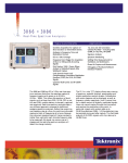
1740A Series NTSC, PAL, and dual-standard models in accessory 1700F02 portable
cases.
Features & Benefits
Composite or Component Waveform Monitoring
Composite Vector Display
Picture Display
Stereo Audio Display
Time Code Phasing and Amplitude
SCH and Color Framing Display
Component Vector, Lightning, Diamond, and Bowtie
Each series includes models for NTSC, PAL, or dual-standard NTSC/PAL
operation. For NTSC models, the last digit of the model number is ’0’
(1740A, 1750A, or 1760); ’1’ for PAL (1741A, 1751A, or 1761); and ’5’ for
dual-standard NTSC/PAL (1745A, 1755A, or 1765).
The family features a common, straightforward operator interface, allowing
the operator to take immediate advantage of the instrument’s extensive
feature set. Each operating mode provides a full set of operating controls,
clearly labeled and within easy reach. Key controls are always available,
with bezel buttons and knobs identified by intuitive on-screen labels.
Data Sheet
Selection Guide
Product
Applications
1740A Series
1750A Series
1760 Series
X
X
X
X
X
X
X
X
X
X
X
X
X
X
X
X
Opt. SC
Composite or
Component
Waveform
Monitoring
Composite Vector
Display
Picture Display
Stereo Audio
Display
Time Code
Phasing and
Amplitude
SCH and Color
Framing Display
Component Vector,
Lightning,
Diamond, and
Bowtie
X
All family members provide the following standard features:
Eight Video Inputs eliminate the requirement for external input selectors,
reducing total system cost in many applications. Since all eight inputs are
connected directly to the instrument, signals may be paraded, overlaid,
or displayed in comparison modes not normally available with a simple
external switcher.
Waveform monitoring is analog for maximum waveform fidelity. There is
no digital processing of the displayed signal. The selected input may be
displayed in one- or two-line or one- or two-field sweeps on a continuous
basis or identified lines of any field may be selected and displayed. Multiple
inputs may be displayed at the same time or multiple filters may be applied
to one input for signal analysis. Time and voltage cursors may be activated
and positioned for reference or measurement.
Composite Vectorscope functions demodulate and display the color
components of the NTSC or PAL signal. A microprocessor-controlled phase
shifter provides accurate vector positioning and eliminates readjustment
when switching between internal and external reference modes. Phase and
amplitude cursors with on-screen readout allow system setup to reproduce
specific chroma values and specific colors when luminance is similarly set
using the waveform-display voltage cursors.
A Picture Monitor mode is provided for easy signal identification. This is
particularly useful when the instrument is used to monitor many sources, as
2
www.tektronix.com
in a production suite or outside production vehicle. In waveform or vector
line select mode, a line bright-up marker in the picture display identifies
the selected line.
Stereo Audio Amplitude and Phase are monitored using a calibrated L/R
Lissajous display. The operator can quickly see that the program audio will
be properly reproduced on both monaural and stereo receivers. Correct
phasing between two audio channels is quickly verified by the direction
of the display; signal level (left + right) is confirmed relative to the CRT
graticule; and stereo separation (left - right) is displayed in quadrature to
the level display.
Audio frequency -3 dB bandwidth is 200 kHz. Phase match between
the left and right channels is better than 1 degree at 20 kHz. Input is
high-impedance bridging, either balanced or unbalanced, to allow signal
monitoring of existing audio circuits.
This display of stereo audio is intuitive and easy to use and has gained wide
acceptance in new-generation Tektronix vectorscopes.
Longitudinal Time Code is monitored in a frame rate display to allow
observation of amplitude, synchronization, and phase with respect to
reference vertical. Synchronization is confirmed by the stationary display
and time code phase is easily determined by horizontal position of the time
code sync word on the CRT.
These monitors provide multiple display modes, allowing simultaneous
observation of the many important parameters that make up a television
signal. For example, vector, waveform, and audio may be displayed
together for an indication of signal quality without operator intervention.
In the 1750A, or 1760 with the SCH option, Subcarrier/Horizontal Phase
and Color Framing are displayed graphically in the patented Tektronix
polar SCH display. Sync jitter over the field is displayed as a moving sync
vector dot or displayed as a timing error at a vertical rate to identify the
relationship over the field time. Correct color framing is quickly verified by
the position of the single sync vector dot relative to the color subcarrier
vector when the monitor is externally referenced.
The SCH phase of the reference signal is separately sensed to allow
reliable SCH and color framing comparison. Using this method of
determining relative SCH phase and color framing eliminates the
requirement for a precise horizontal timing match between the reference
and measured signals and an external color-field identification input is not
required.
Analog Waveform Monitors — 1740A Series • 1750A Series • 1760 Series
User Interface
Characteristic of current-generation Tektronix instruments, an intuitive
operator interface allows full instrument utilization with minimal reference
to the provided user and maintenance manuals. Operating modes, any of
eight video inputs, and key control knobs and buttons are always available
for direct access from the front panel.
To keep operation easy and straightforward, the 1740A, 1750A, and
1760 family "learns" the user’s preferences for waveform, vector, and
picture modes (and SCH in the 1750A and 1760 with the SCH option).
Returning to one of these modes restores the previous configuration.
Changes to a mode configuration are easily made using front-panel buttons,
supplemented by screen-labeled buttons and knobs. Knob operations such
as position, gain, phase, etc., are stored as well.
The 1740A/1750A/1760 family is easily configured for special monitoring
applications, which may be stored in user presets for easy recall. For
example, a program line or off-air VITS may be set up as preset number 3.
Preset number 3 could be named and later recalled to display line 19 of
the selected input in 2H sweep, with voltage cursors marking proper signal
levels. Other presets could be used to immediately access and display
signals from other points in the system. Different operators could quickly
return to preferred monitoring setups after specialized signal checks.
With eight loopthrough video inputs, the 1740A/1750A/1760 family is a
versatile central point system monitor. This capability is particularly useful in
the production studio, where several machines, cameras, and composite
input/output feeds are in use.
As a machine monitor, the instrument may be operated from a central
control panel, with waveform, vector (SCH and color framing with the 1750A
Series and 1760 Series with SCH), audio, time code, and servo signals
easily observed.
High-performance Design
The control system, based on Motorola’s rugged MC68332 32 bit
microprocessor with internal co-processing, facilitates instrument control
and timing functions. Flash EPROMs simplify updating the instrument to the
latest firmware configuration.
The 1740A/1750A/1760 family is based on completely new,
high-performance analog video system electronics. Application Specific
Integrated Circuits (ASICs), developed by Tektronix specifically to maintain
signal fidelity in a television test instrument, handle internal signal routing
and amplification. Video performance is tightly controlled providing
confidence that the signal display accurately represents the signal under
test.
As an example of this new video performance level, the series permits
observation of the video signal at up to x10 vertical and x25 horizontal
magnification. Any part of the signal may be positioned on-screen in
any magnification. Overscan performance at any gain setting is virtually
distortion-free.
DC Offset (position match) between two or more displayed channels is
within 1 IRE or 7 mV. Loopthrough return loss is better than 40 dB to
10 MHz.
Operational Flexibility
Eight loopthrough video inputs may be connected to the rear panel of the
1740A/1750A/1760 Series, eliminating the need for a dedicated routing
switcher bus in many applications. Any of these inputs may be selected
singly or in combination from the front panel or through the RS-232
interface. Input selection may also be included in preset configurations
recalled using a remote control connector.
A separate external input may be selected to synchronize the display,
allowing relative SCH and color framing comparison between two input
signals or with the house reference. Because a separate SCH evaluation is
done on the reference signal, SCH and color framing displays are accurate
over a wide input range.
Signal standards can be automatically selected, NTSC 525/60 or PAL
625/50, in dual-standard 1745A/1755A/1765 models. A CRT graticule
suitable for both standards is provided. A microprocessor-controlled phase
shifter may be activated to rotate the vector display to the correct position on
the display. Once set for each standard, the instrument displays the correct
vector rotation when the video standard is changed.
A new universal input power supply is a part of these monitors. AC mains
in the range of 90 to 250 V, 50 or 60 Hz, are accommodated automatically.
This new power supply will also operate from a nonsinusoidial supply,
allowing battery operation using an external, high-efficiency switching
inverter. A snap-lock power cord appropriate to the country of use is
supplied with each instrument.
www.tektronix.com
3
Data Sheet
Picture display is a standard feature of all models.
1760 Series Lightning Display allows observation of key component values using just
color bars.
Characteristics
Waveform Vertical Deflection
Deflection Factor – 1.0 V (0.2 V x5 gain, 0.1 V x10 gain) input displayed within 1%
of 140 IRE (1.00 V) graticule.
Overscan – <7 mV variation in base line of chroma when positioned anywhere
between sync tip and 100% white.
Variable Gain Range – 0.2x to 1.4x.
DC Offset Between Channels – <1 IRE (7 mV).
Maximum Operating Signal Input Voltage – -1.8 V to +2.2 V, DC + peak AC.
Absolute Maximum Input Voltage – -8.5 V to +8.5 V, DC + peak AC.
Signal Input Impedance – ≥20 kΩ.
75 Ω Loopthrough Return Loss – ≥40 dB to 6 MHz.
Frequency Response –
Flat: Within ± 2% to 10 MHz (x1 gain).
Luminance filter gain of flat response: Within 1% at 50 kHz, <3 dB attenuation at
1 MHz, ≥40 dB attenuation at Fsc.
Chrominance filter, bandwidth 1.5 MHz ±0.3 MHz: Gain within 1% of flat response at
Fsc, attenuation >25 dB at 2 × Fsc.
Differentiated step filter: >40 dB attenuation at Fsc.
Multi-input waveform parade may be offset to display component signals.
Transient Response –
Preshoot, overshoot, ringing, field rate tilt, line rate tilt, differential gain: 1% or better.
Pulse-to-bar ratio: 0.99:1 to 1.01:1.
Pix Out –
Gain unity: ±3%.
Frequency response: ±3% to 6 MHz when terminated in 75 Ω.
Differential gain: ≤1%.
Differential phase: ≤1°.
Return Loss – >30 dB to 6 MHz.
DC Restorer – Slow ≤10%, fast ≥95% attenuation at 50 Hz and 60 Hz.
Offset error: <1 IRE (7 mV).
Fast settling time: ≤6 video lines.
Blanking shift with 10% to 90% APL change: ≤1 IRE (7 mV).
Blanking shift with presence or absence of burst: ≤1 IRE (7 mV).
4
www.tektronix.com
Analog Waveform Monitors — 1740A Series • 1750A Series • 1760 Series
Waveform Horizontal Deflection
SCH Mode (1750A Series)
Sweep – Synchronization triggered by Horiz and Vert sync pulses. Freeruns without
Absolute Accuracy – ±5° at 25 °C.
Relative Accuracy – Typically within 2°.
Acquisition Time – <1 s.
Stable Display – With displayed video to external reference timing from -2 μs to
input.
Timing Accuracy 1 Line, 5 μs/div – ±1%.
2 Line, 10 μs/div – ±1%.
Linearity 1 or 2 Line – ±1%.
Magnified Sweep Accuracy – 1 line x25.
0.2 μS/div – ±1%; 2 line x10.
1.0 μS/div – ±1%.
Magnified Sweep Linearity, 1 or 2 Line Magnified – ±1%. Horizontal position range,
any portion of the synchronized sweep can be positioned on-screen in any sweep
mode.
External Horizontal 0.5 V/div – ±2%.
RGB/YRGB – Staircase input amplitude 12 Vp-p maximum, DC + peak AC not to
exceed -12 V or +12 V, 10 V = 9 div ±1 div display. Field or line rate front-panel
selectable.
Cursor Signals
Waveform Mode Accuracy –
Voltage: ±0.5%.
Timing: ±0.5% for line rate sweeps.
Vector Mode Accuracy –
Amplitude: ±0.5 IRE (0.5%).
Phase: ±0.5°.
Calibrator Signals
Waveform Squarewave –
Amplitude: 1.0 V ±0.5%.
Frequency: 100 kHz ±0.1%.
Waveform Sinewave –
Amplitude: 1.0 V ±0.5%.
Frequency: Nominal subcarrier for standard in use.
+1 μs.
Display Range – ±70° internal reference, 360° external reference.
Component Vector Mode (1760 Series)
Vertical Bandwidth – -3 dB at ≥1.0 MHz.
Horizontal-to-Vertical Bandwidth Matching – No eye opening at 500 kHz or 2 MHz.
Display-to-Graticule Registration – ≤0.25 box.
Component Lightning Mode (1760 Series)
Y – Displayed vertically.
P’b – Displayed horizontally on top half of display.
P’r – Displayed horizontally on bottom half of display.
Component Diamond Mode (1760 Series)
B+G – Displayed vertically vs. B-G horizontally on top half of display.
-(R+G) – Displayed vertically vs. R-G horizontally on bottom half of display.
Component Bowtie Mode (1760 Series)
Common Mode Rejection Ratio – ≥34 dB at 3 MHz.
Y - P’b (CH1 - CH2) – Displayed on left half of display.
Y - P’r (CH1 - CH3) – Displayed on right half of display.
Component Transcoded GBR Outputs (1760 Series)
Input Format – GBR, SMPTE, MII, or Betacam, menu selected.
GBR Output Impedance – Nominally 75 Ω.
DC Level – Back porch clamped to 0 V.
Gain Accuracy – Unity ±3%.
Vector Mode
Input Requirements – 1 Vp-p ±6 dB composite video signal or black burst.
Chrominance Bandwidth – 1 MHz ±200 kHz.
Display – Phase accuracy within 1.25°. Gain accuracy within 2.5%. Quadrature
phasing within 0.5°.
Subcarrier Regenerator –
Pull-in range:
NTSC: ±50 Hz.
PAL: ±10 Hz.
Pull-in time: ≤2 s.
Phase shift with ±50 Hz NTSC or ±10 Hz PAL Fsc change: ≤2°.
Phase shift with ±6 dB burst amplitude change: ≤2°.
Phase shift with video input change: ≤1°.
Phase shift with variable gain +3 dB to -6 dB: ≤0.5°.
Burst jitter: ≤0.5° RMS.
Clamp stability: ≤1/64 in. (0.4 mm).
Phase control range: 360° continuous rotation.
Differential gain: ≤1%.
Differential phase: ≤1°.
www.tektronix.com
5
Data Sheet
1760 Series rear panel. Eight loopthrough inputs may eliminate need for a separate
routing switcher bus.
Environmental
Temperature –
Signals may be displayed in combination modes.
Audio Mode
Full Scale – 0, 4, 8, and 12 dBm, menu selectable.
Full Scale Accuracy – ±0.5 dB at 1 kHz.
Maximum Input Voltage – ±8 Vp-p.
Bandwidth – -3 dB, 200 kHz.
X and Y Input Phase Matching – <1 degree at 20 kHz.
Input Impedance – 20 kΩ nominal.
Time Code Mode
Input – Longitudinal time code, differential.
Full Scale – 0, 4, 8, and 12 dBm, menu selectable.
Maximum Input Voltage – ±8 Vp-p.
Input Impedance – >20 kΩ.
CRT Display
CRT Viewing Area – 80 mm × 100 mm.
Accelerating Potential – Nominally 13.75 kV.
Trace Rotation Range – >1° from horizontal.
Graticule – Internal with variable illumination.
Power Source
Mains Voltage Range – 90 to 250 VAC.
Mains Frequency Range – 50 or 60 Hz.
Power Consumption – 110 VA maximum.
6
www.tektronix.com
Nonoperating: -55 °C to +75 °C.
Operating: 0 °C to +50 °C.
Altitude –
Nonoperating: To 15 km (50,000 ft.).
Operating: To 2,000 m (6,500 ft.).
Vibration – Meets the sine vibration test condition requirements for environmental
class 3 of military specification MIL-T-28800D.
Shock (Nonoperating) – 50 g, 1/2 sine, 11 ms duration, 3 shocks/surface.
Transportation – Qualified under NSTC test procedure 1A, category II (24 in. drop).
Humidity – Will operate at 95% relative humidity for up to 5 days. Do not operate with
visible moisture on the circuit boards.
Certifications
EMC – Certified to the EMC Directive 89/336/EEC.
Safety –
Approved to: UL1244, CSA231.
Complies with: EN61010-1, IEC61010-1.
Physical Characteristics
Dimensions
mm
in.
Height
Width
Length
133.4
215.9
460.4
5.25
8.5
18.125
Weight
kg
lb.
Net
Gross Shipping Weight
3.8
7.2
8
15.7
Analog Waveform Monitors — 1740A Series • 1750A Series • 1760 Series
Ordering Information
1740A
Opt. 74 – White CRT phosphor for these models: 1740A, 1745A, 1750A, 1755A,
1760, 1761, 1765.
Opt. SC – SCH/Color framing option for 1760/1761/1765.
1741A
Optional Accessories
NTSC Waveform/Vector Monitor.
PAL Waveform/Vector Monitor.
Item
Description
1745A
1700F00
Plain cabinet; for half-rack 1700 Series and WFM601 Series,
safety controlled.
Rackmount insert; for WFM700 Series, half-rack
1700 Series, and WFM601 Series.
Portable cabinet; includes handle, feet, and tilt stand.
Filler panel; covers unused rack space in WFM7F05.
Drawer; half-rack, fits WFM7F05 dual-rack cabinet.
Rack adapter; dual side-by-side for WFM700 Series, 1700
Series, and WFM601 Series.
Kit to add Opt. SC to 1760/1761/1765.
Viewing hood.
Snap-on front cover.
NTSC/PAL Waveform/Vector Monitor.
1750A
NTSC Waveform/Vector/SCH Monitor.
1751A
PAL Waveform/Vector/SCH Monitor.
1755A
NTSC/PAL Waveform/Vector/SCH Monitor.
1700F00A
1700F02
1700F06
1700F07
WFM7F05
1760
NTSC/Component Waveform/Vector Monitor.
040-1488-xx
016-0475-xx
200-3897-xx
1761
Service
PAL/Component Waveform/Vector Monitor.
Opt. R5 – Repair Service 5 Years.
1765
NTSC/PAL/Component Waveform/Vector Monitor.
All Include: User manual, spare fuse, and air filter. To meet safety listing
requirements, order a cabinet or rackmount from optional accessories list.
Product(s) are manufactured in ISO registered facilities.
www.tektronix.com
7
Data Sheet
Contact Tektronix:
ASEAN / Australasia (65) 6356 3900
Austria +41 52 675 3777
Balkans, Israel, South Africa and other ISE Countries +41 52 675 3777
Belgium 07 81 60166
Brazil +55 (11) 40669400
Canada 1 (800) 661-5625
Central East Europe, Ukraine, and the Baltics +41 52 675 3777
Central Europe & Greece +41 52 675 3777
Denmark +45 80 88 1401
Finland +41 52 675 3777
France +33 (0) 1 69 86 81 81
Germany +49 (221) 94 77 400
Hong Kong (852) 2585-6688
India (91) 80-42922600
Italy +39 (02) 25086 1
Japan 81 (3) 6714-3010
Luxembourg +44 (0) 1344 392400
Mexico, Central/South America & Caribbean 52 (55) 54247900
Middle East, Asia, and North Africa +41 52 675 3777
The Netherlands 090 02 021797
Norway 800 16098
People’s Republic of China 86 (10) 6235 1230
Poland +41 52 675 3777
Portugal 80 08 12370
Republic of Korea 82 (2) 6917-5000
Russia & CIS +7 (495) 7484900
South Africa +27 11 206 8360
Spain (+34) 901 988 054
Sweden 020 08 80371
Switzerland +41 52 675 3777
Taiwan 886 (2) 2722-9622
United Kingdom & Ireland +44 (0) 1344 392400
USA 1 (800) 426-2200
For other areas contact Tektronix, Inc at: 1 (503) 627-7111
Updated 30 October 2008
For Further Information. Tektronix maintains a comprehensive, constantly expanding
collection of application notes, technical briefs and other resources to help engineers working
on the cutting edge of technology. Please visit www.tektronix.com
Copyright © Tektronix, Inc. All rights reserved. Tektronix products are covered by U.S. and foreign patents,
issued and pending. Information in this publication supersedes that in all previously published material.
Specification and price change privileges reserved. TEKTRONIX and TEK are registered trademarks of
Tektronix, Inc. All other trade names referenced are the service marks, trademarks, or registered trademarks
of their respective companies.
27 Jul 2009
www.tektronix.com
24W-07169-4d