1
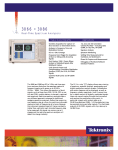
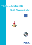
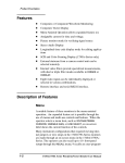
Data Pattern Generator
DG2040 • DG2030 • DG2020A
Features & Benefits
Data Rate to 1.1 Gb/s Tests
High-speed Logic Devices
and Circuits
Data Pattern Depth to
256 K/Channel Speeds
Characterization
Multiple Output Channels
Increases Flexibility
– DG2040: 2
– DG2030: 4 or 8
– DG2020A: 12, 24, or 36
Control of Edge Timing
(DG2040) Permits Jitter
Simulation in Serial Data
Streams
Precise Control of Output
Parameters Include:
– Variable Output Delay
– Variable Output Level
– Variable Rise and Fall Time
Control (DG2030)
– Tri-state Output Control
(DG2020A, DG2030)
DG2000 Series.
The DG2000 Series of pattern generators
provide digital designers with the high
performance tools needed to evaluate
advanced digital semiconductors and logic
circuits. Whatever you call your design
process – characterization, debug, validation
or verification – as a digital designer you
must have a state-of-the-art digital pattern
generation as you push the edge of the
technology envelope and race to market.
Fast Transition Times to
150 ps (DG2040) Aids Fast
Logic Evaluation
Choose the Best Fit
The DG2000 Series is remarkable for its
balanced approach to providing the appropriate class of instrument for a wide variety
of digital design applications. Performance
ranges from 1.1 Gb/s to 200 Mb/s and
from 2 to 36 channels. The table illustrates
the principal specifications for members of
the DG2000 Series.
Complementary Output
(DG2040) Assures Excellent
Signal Fidelity
Flexible Sequence Control
with Jump, Event and
Nested Loops
Import Pattern Data with
DG-link Software Utility
Applications
Ultra Low Jitter for
Clock Substitution
Characterize Device Timing
for TTL, CMOS, ECL Families
Simulate Missing Functions
in System or Subsystem
Evaluation
Create Complex Data
Patterns with Sophisticated
Sequence, Looping, Jump
on Event and Tri-state
Output Control
Characterize and Verify ASIC,
FPGA and DACs
Test Printer Engines or
LCD Display Drivers
Use in Conjunction with
TLA Logic Analyzer to
Provide Digital Stimulus
1
Data Pattern Generator • www.tektronix.com/signal_sources
Data Pattern Generator
DG2040 • DG2030 • DG2020A
DG2000 Series Principal Specifications
Data Rate
Pattern Depth
Rise & Fall Time
(20% to 80%)
No. of Channels
Features
DG2040
DG2030
DG2020A
1.1 Gb/s
400 Mb/s
200 Mb/s
256 K/CH.
256 K/CH.
64 K/CH.
150 ps at 1 Vp-p
1.5 ns at 2.5 Vp-p
2 ns at 5 Vp-p
2
4 or 8
12, 24 or 36
Edge control
Variable tr & tf time
Bus wide testing
Critical Timing
The DG2000 Series is the ideal solution for
applications where you must characterize
device or circuit timing and amplitude margins.
The DG2000 Series is perfect for simulating
setup and hold violations or conditions of
metastability. The DG2000 graphical user
interface allows you to quickly create complex
data patterns with a few keystrokes on the
front panel. Use the advanced sequence
editing capability of the DG2000 Series to
insert infrequent faults or glitches in your
data patterns to verify device or circuit
recovery. The DG2000 Series is an invaluable
tool, allowing you to simulate missing system
functionality while meeting critical market
windows. With the introduction of the
DG2040, new capabilities are available to
control clock and data jitter or modulate
pulse edges on a selective basis (Figure 1).
2
Data Pattern Generator • www.tektronix.com/signal_sources
Figure 1. The DG2040 allows specific edges to be identified and time adjusted or jittered by
±100 ps. An external modulation source can be used to provide continuously variable jitter.
Data Pattern Generator
DG2040 • DG2030 • DG2020A
Characteristics
Output Data
DG2040
DG2030
DG2020A
Data Rate
0.1 b/s to 1100 Mb/s
0.1 b/s to 409.6 Mb/s
0.1 b/s to 200 Mb/s
Sampling Rate
0.1 Hz to 1100 MHz
0.1 Hz to 409.6 MHz
0.1 Hz to 200 MHz
7 digits
7 digits
4 digits
Resolution
Clock Output Period Jitter
<30 psp-p at 1100 MHz. Typical
<50 psp-p at 200 MHz. Typical
<50 psp-p at 200 MHz. Typical
CH0 Period Jitter (Clock Pattern)
<20 psp-p at 1100 MHz. Typical
<200 psp-p at 400 MHz. Typical
<35 psp-p at 200 MHz. Typical
Accuracy
PLL On, ±0.0001%
PLL On, ±0.0001%; PLL Off, ±3%
PLL On, ±0.005%; PLL Off, ±3%
360 to 256 Kbits (4 increment)
90 to 256 Kbits (1 increment)
64 to 64 Kbits (1 increment)
2-Bits (complementary outputs) via
front-panel SMA connectors
Standard: 4-Bits via front-panel
BNC connectors
Optional: 8-Bits via 4 front-panel,
4 rear-panel BNC connectors
Standard: 12-Bits
Optional: 24- or 36-Bits
Pattern Depth
Data Width
Sequencer
Maximum Number of Blocks – 256.
Maximum Number of Sequence Steps –
DG2040: 4000.
DG2030: 4000.
DG2020A: 2048.
Block Repeats Per Line – 1 to 65536 or infinite.
Internal Trigger Generator
(DG2030, DG2040)
Range – 1.0 µs to 10.0 s.
Resolution – 3 digits, 0.1 µs minimum.
Accuracy – ±0.01%.
Data and Clock Output
(DG2040)
Data –
Output:
Standard: CH 0 & CH 1 at front-panel SMA and
Clock at rear panel SMA connectors.
VOH: – 0.875 V to +3.5 V into 50 Ω.
VOL: –1.125 V to +3.25 V into 50 Ω.
Resolution: 5 mV.
Maximum Swing: 2.5 Vp-p into 50 Ω.
Minimum Swing: 250 mVp-p into 50 Ω.
DC Accuracy: ±3% of set value ± 50 mV.
Aberrations:
Overshoot <5% at 1.5 Vp-p at 10 MHz.
Undershoot: <5% ±1.5 Vp-p at 10 MHz.
Impedance: 50 Ω.
Rise/Fall Time (20 to 80%): <150 ps at 1 Vp-p and
10 MHz.
Delay Function:
Delay Channel: CH 0 or CH 1.
Delay Time: –1 ns to +2 ns.
Delay Resolution: 10 ps.
Accuracy: < (±3% of setting) ± | 25 ºC – Ta | *
15 ps ±100 ps (where Ta is the ambient
temperature ºC).
Channel Skew: (<± | 25 ºC – Ta | * 15 ps ±100 ps)
where Ta is the ambient temperature ºC.
Data Pattern Generator • www.tektronix.com/signal_sources
3
Data Pattern Generator
DG2040 • DG2030 • DG2020A
Data and Clock Output
(DG2030)
Data –
Output:
Standard: CH 0 to CH 3 and Clock at front-panel
BNC connectors.
Optional: CH 4 to CH 7 at rear-panel BNC
connectors.
VOH: –1.25 V to +3.5 V into 50 Ω.
VOL: –1.50 V to +3.25 V into 50 Ω.
Resolution: 5 mV.
Maximum Swing: 5 Vp-p.
Minimum Swing: 250 mVp-p.
DC Accuracy: (±3% of set value) ± 50 mV.
Aberrations: ≤5% at 3.5 Vp-p.
Impedance: 50 Ω.
Rise/Fall Time (20 to 80%): Variable at amplitude
range from 2 Vp-p to 5 Vp-p.
Variable Range: 2.1 ns to 4.7 ns at 3.00 Vp-p –
depends on amplitude setting.
Value in Fast: 0.25 Vp-p to 1 Vp-p; 500 ps.
1.7 ns at 3.00 Vp-p.
Accuracy: ±10% of setting ±500 ps.
Delay Function:
Delay Channel: CH 0 to CH 7.
Delay Time: –5 ns to 18 ns.
Delay Resolution: 20 ps.
Accuracy: ±(3% of setting) ± | 25 – Ta | * 60 ps
±500 ps (where Ta is the ambient
temperature ºC).
Channel Skew: <±300 ps (referenced to the clock
output) at 10 MHz.
Deskew Range: ±1 ns.
Resolution: 10 ps.
4
Clock –
Amplitude: ±5% of setting ±50 mV at 1 MHz clock.
Aberration: ≤5% at 3.5 Vp-p.
Impedance: 50 Ω.
Rise/Fall Time (20 to 80%): Variable at amplitude
range is 2 Vp-p to 5 Vp-p.
Variable Range: Depends on amplitude setting.
Value in Fast: 0.25 Vp-p to 1 Vp-p; 500 ps.
1.7 ns at 3.00 Vp-p.
Accuracy: ±10% of setting ±500 ps.
Auxiliary Inputs
Clock –
DG2040: Rear-panel BNC connectors (10 MHz
reference).
DG2030: Rear-panel BNC connector.
DG2020A: Rear-panel SMB connector.
Frequency:
DG2040: 10 MHz ±0.1 MHz.
DG2030: DC to 409.6 MHz.
DG2020A: DC to 200 MHz.
DG2040 –
Input voltage range: 0.2 V to 3.0 Vp-p.
Input voltage level: ±10 Vmax.
Impedance: 50 Ω, AC coupling.
DG2020A and DG2030 –
Impedance: 50 Ω, terminated to +0.5 V.
Delay to Clock Out: 36 ns (typical).
Trigger –
Front-panel BNC connector.
Level: –5.0 V to +5.0 V.
Resolution: 0.1 V.
Threshold accuracy: ±(5% of setting) ±0.1 V.
Minimum Pulse Width: ≥10 ns.
Sensitivity: >0.5 Vp-p.
Impedance: 1 kΩ or 50 Ω.
Data Pattern Generator • www.tektronix.com/signal_sources
Maximum Input: ±10 V into 1 kΩ, ±5 V into 50 Ω.
Polarity: Positive or negative.
Hold Off:
DG2040: 100 ns minimum.
DG2030: 100 ns minimum.
DG2020A: 500 ns minimum.
Event (DG2040 and DG2030 only) –
Rear-panel BNC connector.
Threshold Level: –5.0 V to +5.0 V.
Resolution: 0.1 V.
Set-up Time to Next Block:
DG2040: 230.5 to 254.5 clocks before
the next block.
DG2030: 48 to 53 clocks before the
next block.
Polarity: Positive edge.
Minimum Pulse Width: 100 ns.
Inhibit (DG2030 only) –
Rear-panel BNC connector.
Mode:
Off: Always enabled.
Internal: Controlled by CH 0 signal.
External: Controlled by inhibit input signal.
Both: Controlled by CH 0 or inhibit input signal.
Threshold Level: –5.0 V to +5.0 V into 1 kΩ.
Resolution: 0.1 V.
Delay to Data Output: 34 ns to 38 ns (typical).
Delay to Clock Output: 7 ns to 11 ns (typical).
Auxiliary Outputs
Sync –
DG2040: Rear-panel BNC connector.
DG2030: Rear-panel BNC connector.
DG2020A: Front-panel BNC connector.
Level:
VOH, 2.5 V into 50 Ω
VOL, 0 V into 50 Ω.
Pulse Width:
DG2040: 32 to 36 clocks.
DG2030: 9 or 10 clocks.
DG2020A: 6 clocks.
Impedance: 50 Ω.
Data Pattern Generator
DG2040 • DG2030 • DG2020A
Event –
DG2040: Rear-panel BNC connector.
DG2030: Rear-panel BNC connector.
DG2020A: Front-panel BNC connector.
Level:
DG2040: VHI, 2.5 V into 50 Ω; VLO, 0 V into
50 Ω.
DG2030: VOH, 2.5 V into 50 Ω; VOL, 0 V into
50 Ω.
DG2020A: Positive TTL pulse, 50 Ω.
Output Term:
DG2040: 180 to 200 clocks.
DG2030: 45 to 50 clocks.
DG2020A: 8 clocks.
Delay Time:
DG2040: 194.5 to 214.5 clocks before data
output change.
DG2030: 48 to 53 clocks before data output
change.
DG2020A: 22 clocks before data output change.
Impedance: 50 Ω.
Clock (DG2020A only) –
Rear-panel SMB connector.
Level: 1 V (typical) into 50 Ω.
Delay From Trigger Input:
PLL On:
>6.25 MHz: 15 to 40 ns.
<6.25 MHz: 25 to 60 ns.
PLL Off:
>6.25 MHz: 15 to 45 ns.
<6.25 MHz: 25 to 60 ns.
External: 7 ns + 1 clock to 20 ns + 0.5 clock.
P3410 TTL Data Output
Pod Characteristics
Event Input
Data Output
Delay to Data Output – ≤50 ns + 50 clocks.
Channels – 12.
Set-up Time to Next Block – 47 to 54 clocks.
Connector – 26-Pin header.
Threshold Level – TTL.
Inhibit Input
VOH – >4.4 V into 1 MΩ.
Level – TTL, 1 kΩ.
VOL – >0.1 V into 1 MΩ.
Delay to Data Output – 18 ns.
Rise/Fall Time – <5 ns into 1 MΩ, 10 pF
(20% to 80%).
Internal Inhibit Delay – 5 ns.
Internal Clock Out to Data Delay – 24 ns.
External Clock Input to Data Output Delay –
25 to 45 ns.
Trigger Input to Data Output Delay –
Internal Clock:
>6.25 MHz: 30 to 65 ns.
<6.25 MHz: 45 to 80 ns.
External Clock: 25 ns + 0.5 clock to 45 ns +
1.5 clock.
Physical Characteristics
Dimensions
Height*1
Width
Depth
Weight
Net
mm
51
150
101
kg
0.5
in.
2.0
5.9
4.0
lb.
1.1
*1 Including feet.
Delayed Channels
Delay Channel – CH 8, CH 9, CH 10, CH 11.
Delay Time – 0 to 20 ns.
Delay Resolution – 0.1 ns.
Channel Skew –
CH 0 and other channels, same pod: <3 ns.
CH 0 and CH 0, two pods of same type: <2 ns.
Programmable Interface –
GPIB: ANSI/IEEE 488.2-1987.
RS-232-C: 19.2 Kb/s, D-sub 9-Pin connector.
Data Pattern Generator • www.tektronix.com/signal_sources
5
Data Pattern Generator
DG2040 • DG2030 • DG2020A
P3420 Variable Data
Output Pod Characteristics
Event Input
Certification and Compliance
Threshold Level – –5.0 V to +5.0 V.
Data Output
Resolution – 0.1 V.
Channels – 12.
Delay to Data Output – ≤45 ns + 50 clock.
EC Declaration of Conformity – Meets intent
of Directive 89/336/EEC for electromagnetic
compatibility.
Connector – SMB.
Set-up Time to Next Block – 47 to 54 clocks.
Safety – UL1244, CSA231, EN61010-1,
IEC61010-1.
VOH – –2.0 V to +7.0 V into 1 MΩ.
Inhibit Input
VOL – –3.0 V to +6.0 V into 1 MΩ.
Threshold Level – –5.0 V to +5.0 V, 1 kΩ.
Power
Resolution – 0.1 V.
Resolution – 0.1 V.
Maximum Swing – 9.0 Vp-p.
Delay to Data Output – 16 ns.
Minimum Swing – 0.5 Vp-p.
Internal Inhibit Delay – –2 ns.
Output Current –
Total Output Current: <500 mA.
Sink: <–30 mA/CH.
Source: >+30 mA/CH.
Rise/Fall Time – <2 ns into 1 MΩ, 10 pF,
5 Vp-p swing (20% to 80%).
Internal Clock Out to Data Delay – 20 ns.
External Clock Input to Data Output Delay –
20 to 40 ns.
Trigger Input to Data Output Delay –
Internal Clock:
>6.25 MHz: 30 to 60 ns.
<6.25 MHz: 40 to 70 ns.
External Clock: 20 ns + 0.5 clock to 40 ns +
1.5 clock.
Delayed Channels
Delay Channel – CH 8, CH 9, CH 10, CH 11.
Delay Time – 0 to 20 ns.
Delay Resolution – 0.1 ns.
Channel Skew –
CH 0 and other channels, same pod: <3 ns.
CH 0 and CH 0, two pods of same type: <2 ns.
Physical Characteristics
Dimensions
Height*1
Width
Depth
Weight
Net
mm
51
255
161
kg
1
in.
2
10
6.3
lb.
2.2
*1 Including feet.
General Characteristics
Environmental
Temperature –
Operating: +10 ºC to +40 ºC.
Nonoperating: –20 ºC to +60 ºC.
Humidity –
Operating: 20% to 80% (no condensation).
Nonoperating: 5% to 90% (no condensation).
Altitude –
Operating: Up to 4.5 km (15,000 ft.).
Nonoperating: Up to 15 km (50,000 ft.).
Vibration – Operating: 0.33 mm p-p, 10 to 55 Hz,
15 minutes.
Shock – Nonoperating: 294 m/s2 (30 g), half-sine,
11 ms duration.
6
Data Pattern Generator • www.tektronix.com/signal_sources
AC Line Power –
Voltage Ranges: 90 to 250 VAC.
Nominal Voltage: 100 V, 115 V, 200 V, 230 V, 240 V.
Line Frequency:
90 to 250 VAC: 48 to 63 Hz.
90 to 127 VAC: 48 to 440 Hz.
Power Consumption – 300 W maximum.
Maximum Current – 4 A.
Physical Characteristics
DG2000 SERIES MAIN FRAME
Dimensions
mm
Height*1
164
Width*2
362
Depth*3
491
Weight
kg
Net
9.7
in.
6.4
14.3
8.25
lb.
21.4
*1 Including feet.
*2 Including handle.
*3 Including front cover. 576 mm (22.2 in.) with handle
extended.
Characteristics shown are typical. Please refer to individual
product user manuals for complete specifications.
Data Pattern Generator
DG2040 • DG2030 • DG2020A
Ordering Information
DG2040
Data Generator.
Includes: User Manual (071-0257-50),
Programmer Manual (071-0258-50), 3.5 in.
Performance Check Disk (063-3121-50), GPIB
Sample Program Disk (063-3122-50), DG-link
Application Software (063-2920-50), Power Cord,
ISO Qualified Inspection Passed Certificate.
Please specify power plug when ordering.
Options
Opt. 1R – Rackmount. Floppy drive access moved
to front panel.
DG2030
Recommended
Accessories
P3410
TTL-level Pod with 12 Output Channels.
Includes: Pin Header-to-Pin Header Output Cable
Set (012-1502-00) for 12 Output Channels, ISO
Qualified Inspection Passed Certificate.
P3420
Variable-level Pod with 12 Output Channels.
Includes: SMB-to-Pin Header Output Cable Set
(012-1504-00) for 12 output channels, ISO
Qualified Inspection Passed Certificate.
DG2000 Series
Power Plug Options
Data Generator.
Includes: User Manual (071-0059-50),
Programmer Manual (071-0057-50), 3.5 in.
Performance Check Disk (063-2922-50), GPIB
Sample Program Disk (063-2921-50), DG-link
Application Software (063-2920-50), Power Cord,
ISO Qualified Inspection Passed Certificate.
Please specify power plug when ordering.
Opt. A0 – US Plug, 115 V, 60 Hz.
Opt. A1 – Euro Plug, 220 V, 50 Hz.
Opt. A2 – UK Plug, 240 V, 50 Hz.
Opt. A3 – Australian Plug, 240 V, 50 Hz.
Opt. A4 – N. American Plug, 240 V, 50 Hz.
Opt. A5 – Swiss Plug, 220 V, 50 Hz.
Options
DG2000 Series Service
Opt. 01 – Eight-channel output. Adds four-channel
output from rear panel.
Opt. 1R – Rackmount. Floppy drive access moved
to front panel.
Opt. C3 – Calibration Service 3 Years.
Opt. D1 – Calibration Data Report.
Opt. D3 – Calibration Data Report 3 Years
(with Option C3).
Opt. R3 – Repair Service 3 Years.
DG2020A
Data Generator.
Includes: User Manual (071-0053-50),
Programmer Manual (071-0054-50), 3.5 in.
Performance Check Disk (063-2918-50),
GPIB Sample Program (063-2919-50), DG-Link
Application Software (063-2920-50), Pod
Connection Cable (174-3548-00), Power Cord,
ISO-qualified Inspection Passed Certificate.
Order P3410 or P3420 Pod separately.
Please specify power plug when ordering.
50 Ω BNC-to-BNC Cable (Single shield) – Order
012-1342-00.
50 Ω BNC-to-BNC Cable (Double shield) – Order
012-1256-00.
50 Ω BNC-to-SMB Cable (40 in.) – Order
012-1459-00.
50 Ω BNC Male-to-SMB Female Adapter – Order
015-0671-00.
One-channel Pin Lead Set (Set of 5) – Order
012-1508-00.
Four-channel Pin Lead set (Set of 3) – Order
012-1509-00.
Connector (for Pin-header) – Order
131-5919-00.
GPIB Cable – Order 012-0991-00.
Replacement 1.2 m POD Connection Cable
(standard accessory) – Order 174-3548-00.
50 Ω SMA male to SMA male; 12 in. – Order
174-1364-00.
50 Ω SMA male to SMA male; 20 in. – Order
174-1427-00.
50 Ω SMA male to SMA male; 60 in. – Order
174-1428-00.
50 Ω SMA male to SMA male; 2 m – Order
174-0679-00.
50 Ω SMA male to SMA male; 8.5 in. – Order
174-1120-00.
50 Ω SMA male to SMA male; 1 m – Order
174-1341-00.
Documentation
P3410 and P3420 POD
Service
Opt. D1 – Calibration Data Report.
Opt. R3 – Repair Service 3 Years.
Recommended
Accessories
DG2020A Service Manual – Order 071-0055-50.
DG2030 Service Manual – Order 071-0058-50.
DG2040 Service Manual – Order 071-0259-50.
DG2020A Twelve-Channel Upgrade Kit (Provides
same function as DG2020A Opt. 01) – Order
040-1556-50.
Warranty – One year parts and labor.
PODS (DG2020A)
Options
Cables, Adapters
and Connectors
Opt. 01 – Adds a 12-Bit digital port for a total
of 24 output channels. Includes pod connection
cables (174-3548-00). Order P3410 or P3420
pod separately.
Opt. 02 – Adds two 12-Bit digital ports for a total
of 36 output channels. Includes two pod connection
cables (174-3548-00). Order P3410 or P3420
pod separately.
Opt. 1R – Rackmount. Floppy drive moved to
front panel.
SMB-to-Pin Header Cable (20 in.) – Order
012-1503-00.
SMB-to-Pin Header Cable (50 in.) – Order
012-1506-00.
Pin Header-to-Pin Header Cable – Order
012-1505-00.
SMB-to-SMB Cable (40 in.) – Order
012-1458-00.
Data Pattern Generator • www.tektronix.com/signal_sources
7
Data Pattern Generator
Contact Tektronix:
ASEAN / Australasia / Pakistan (65) 6356 3900
DG2040 • DG2030 • DG2020A
Austria +43 2236 8092 262
Belgium +32 (2) 715 89 70
Brazil & South America 55 (11) 3741-8360
Canada 1 (800) 661-5625
Central Europe & Greece +43 2236 8092 301
Denmark +45 44 850 700
Finland +358 (9) 4783 400
France & North Africa +33 (0) 1 69 86 80 34
Germany +49 (221) 94 77 400
Hong Kong (852) 2585-6688
India (91) 80-2275577
Italy +39 (02) 25086 1
Japan 81 (3) 6714-3010
Mexico, Central America & Caribbean 52 (55) 56666-333
The Netherlands +31 (0) 23 569 5555
Norway +47 22 07 07 00
People’s Republic of China 86 (10) 6235 1230
Poland +48 (0) 22 521 53 40
Republic of Korea 82 (2) 528-5299
Russia, CIS & The Baltics +358 (9) 4783 400
South Africa +27 11 254 8360
Spain +34 (91) 372 6055
Sweden +46 8 477 6503/4
Taiwan 886 (2) 2722-9622
United Kingdom & Eire +44 (0) 1344 392400
USA 1 (800) 426-2200
USA (Export Sales) 1 (503) 627-1916
For other areas contact Tektronix, Inc. at: 1 (503) 627-7111
Updated 23 December 2003
Our most up-to-date product information is available at:
www.tektronix.com
Product Area Assessed: The planning, design/development and manufacture
of electronic Test and Measurement instruments.
Product(s) complies with IEEE Standard 488.1-1987, RS-232-C, and with
Tektronix Standard Codes and Formats.
Copyright © 2004, Tektronix, Inc. All rights reserved. Tektronix products are covered
by U.S. and foreign patents, issued and pending. Information in this publication
supersedes that in all previously published material. Specification and price change
privileges reserved. TEKTRONIX and TEK are registered trademarks of Tektronix,
Inc. All other trade names referenced are the service marks, trademarks or registered trademarks of their respective companies.
02/04
8
Data Pattern Generator • www.tektronix.com/signal_sources
HB/SFI
87W-10799-3