Download Features Description of Features
Transcript
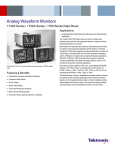
Product Description
Features
H
Composite or Component Waveform Monitoring
H
Composite Vector Display
H
Menu-Assisted Operation allows expanded feature set.
H
Assignable cursors for time and voltage.
H
Picture monitor mode for verifying signal source
H
Stereo Audio Display
H
Longitudinal time code display mode for editing applications
H
SCH and Color Framing Display (1750A-- Series only)
H
External staircase from a camera control unit can be
selected remotely.
H
Internal video filters provide specialized measurements,
with dual or triple filter modes available in PARADE or
OVERLAY.
H
Eight video inputs can be individually displayed or
selected in various combinations.
H
Remote interface and serial RS232 interface.
Description of Features
Menu
A notable feature of these monitors is the menu-assisted
operation. An expanded feature set is possible through the
use of menus and multi-use controls and buttons. When the
operator selects a menu item, such as VOLTAGE/TIMING
CURSORS, VARIABLE GAIN, or LINE SELECT, an on-screen
label shows the current function of the controls.
Many instrument configurations that required moving internal jumpers or wire straps in the 1740/1750-- Series monitors
are made through an on-screen menu in the 1740A/ 1750A-Series. The operator can also recall up to 10 front-panel
setups through the RECALL menu; 9 recalls are user-program-
1-2
1740A/1750A Series Waveform/Vector Monitor User Manual
Appendix A: Performance Specification
Electrical Specifications
Table A- 1: Waveform Vertical Deflection
CATEGORY
DESCRIPTION
Deflection Factor
Req: 1 V full scale (X1): 1 volt input displayed with-
in 1% of 140 IRE (1.00 V PAL)
X5 Gain: 0.2 volt input displayed within
1% of 140 IRE (1.00 V PAL)
X10 Gain: 0.1 volt input displayed within 1%
of 140 IRE (1.00 V PAL)
RI:
Any one of the 8 inputs
Variable Gain Range
Req: 0.2X to 1.4X
Overscan
Req: ≤1% variation in baseline of chroma when
positioned anywhere between sync tip and
100% white
RI:
X1, X5, or X10 with any variable gain
setting
Video Maximum Operating
Input Voltage
RI:
--1.8 V to +2.2 V, (all inputs, A -- B3)
dc+peak ac
Absolute Video Input Voltage
RI:
--8.5 V to +8.5 V (dc+peak ac)
Video Input DC Impedance
RI:
≥20kΩ
Video Input Return Loss
RI:
Typically ≥40 dB to 6 MHz
Video Input DC Offset
Between Channels
Req: ≤1 IRE (7 mV PAL)
RI:
Typically ≤1 mV
Video Input Offset Range
RI:
CHA2, A3, B2, & B3 can be offset from
CHA1 or CHB1 by ±350 mV
Video Input Loop-Through
Isolation
RI:
Typically
A-2
≥70 dB
1740A/1750A Series Waveform/Vector Monitor User Manual
Appendix A: Performance Specification
Table A- 1: Waveform Vertical Deflection (Cont.)
CATEGORY
Video Input Crosstalk Between
Channels
Frequency Response (Flat)
DESCRIPTION
RI:
Req: ±2% to 10 MHz (X1 Gain) ±4% to 10 MHz
(X5 and X10 Gain), on screen signal (0.2 V or
0.1 V)
RI:
Luminance Filter Gain
All inputs ac or dc coupling
Req: 1 ±1%
RI:
Luminance Filter Response
Typically ≥60 dB
Reference is FLAT at 50 kHz
Req: ≤3 dB attenuation at 1 MHz
≥40 dB attenuation at FSC
Luminance Filter Chrominance
Rejection
(1745A & 1755A only)
Req: ≤34 dB
Chrominance Filter Gain
Req: 1 ±1%
RI:
Chrominance Filter Bandwidth
Ref. is flat at FSC (3.58 or 4.43 MHz)
Req: 1.5 MHz ±0.3 MHz
RI:
Centered at FSC. Passband is typically
FSC + and -- 750 kHz
Chrominance Filter
Attenuation at 2X FSC
RI:
≥25 dB
Differentiated Step Filter
Attenuation at 2X FSC
RI:
≥40 dB
1740A/1750A Series Waveform/Vector Monitor User Manual
A-3
Appendix A: Performance Specification
Table A- 1: Waveform Vertical Deflection (Cont.)
CATEGORY
DESCRIPTION
Transient Response
Req: Pulse-to-Bar Ratio 0.99:1 to 1.01:1
RI:
Preshoot ≤1%
RI:
Overshoot ≤1%
RI:
Ringing ≤1%
Req: Field-Rate Tilt ≤1%
Req: Line-Rate Tilt
RI:
Differential Gain
Pix Out Gain
Req: 1±3%
Pix Out Frequency Response
Req: ±3% to 6 MHz
Pix Out Differential Gain
RI:
≤1%
Pix Out Differential Phase
RI:
≤1°
Pix Out Output Impedance
RI:
75Ω
Pix Out Return Loss
≤1%
Req: ≥ 30 dB to 6 MHz
Pix Out Line Select Strobe
DC Restorer 60 Hz (50 Hz)
Attenuation
RI:
DC Restorer Offset Error
A dc offset is added to output in line select to bright up the selected line or lines.
Req: Slow Mode ≤10%
Fast Mode ≥95%
RI:
Back porch or sync tip clamp point is
selected through menu.
Req: ≤1 IRE (7 mV PAL)
Fast Settling Time
Blanking Shift with 10 to 90%
APL Change
A-4
≤1%
RI:
Typically 3 mV
RI:
≤6 video lines
Req: ≤1 IRE (7 mV PAL)
1740A/1750A Series Waveform/Vector Monitor User Manual
Appendix A: Performance Specification
Table A- 1: Waveform Vertical Deflection (Cont.)
CATEGORY
DESCRIPTION
Blanking Shift with Presence
and Absence of Burst
Req: ≤1 IRE (7 mV PAL)
RI:
Typically 3 mV
Table A- 2: External Reference
CATEGORY
DESCRIPTION
Input
RI:
Composite video or black burst
Maximum Operating Input
Voltage
RI:
--1.8 V to +2.2 V, dc + peak ac
Absolute Maximum Input
Voltage
RI:
--8.5 V to +8.5 V, dc + peak ac
DC Input Impedance
RI:
≥20 kΩ
Return Loss
RI:
Typically ≥40 dB to 6 MHz
1740A/1750A Series Waveform/Vector Monitor User Manual
A-5
Appendix A: Performance Specification
Table A- 3: Waveform Horizontal Deflection
CATEGORY
DESCRIPTION
Sweep
Req: Synchronization: Sweep triggered by horizon-
tal and vertical sync pulses
Sweep Timing Accuracy
RI:
Sweep Length: ≈12 divisions
RI:
Sweep freeruns without input
Req: 1 Line:
2 Line:
RI:
5 s/division ±1%
10 s/division ±1%
1 Field: displays one full field, including
field rate sync
2 Field: displays two full fields and
the field rate sync between them
Sweep Linearity
Req: 1 line: ±1%
2 line: ±1%
Magnified Sweep Accuracy
Req: 1 Line: 0.2 s/division ±1%
2 Line: 1.0 s/division ±1%
Magnified Sweep Linearity
Req: 1 line: ±1%
2 line: ±1%
Horizontal Position Range
Req: Any portion of the synchronized sweep can be
positioned on screen in all sweep modes.
External Horizontal Input
Remote Sync
A-6
Req: 2 divisions/volt, ±2%
RI:
Menu is selected and enabled by REMOTE connector ground closure.
RI:
Input Amplitude: TTL level
RI:
Frequency: 25 Hz to 100 Hz positive
edge-triggered sweep
RI:
Enabling Signal: TTL low or ground
closure
1740A/1750A Series Waveform/Vector Monitor User Manual
Appendix A: Performance Specification
Table A- 4: Measurement Cursors
CATEGORY
DESCRIPTION
Waveform Accuracy
Req: Voltage: 0.5%
Timing: 0.5%, for line rate sweeps
RI:
Vector Accuracy
Typically 0.5% for field rate sweeps
Req: Gain: ±1.5%
Phase: ±1°
RI:
Measured with respect to the Color
Bar signal
Table A- 5: RGB/YRGB
CATEGORY
DESCRIPTION
RGB/YRGB
Req: Staircase input gain: 0.8 V/division ±10%
RI:
RGB Sweep Length:
1 Field ≈30% of normal
1 Line ≈ 30% of normal
RI:
YRGB Sweep Length:
1 Field ≈ 25% of normal
1 Line ≈ 25% of normal
RI:
Maximum staircase operating signal: DC
signal plus peakacnotto exceed --12 V
to+12 V. Line or field rate sweep.
RI:
Peak-to-peak acsignal not to exceed
12 V.
RI:
Sweep Repetition Rate: Field or line rate
of displayed video or external
sync signal as selected by the frontpanel sweep selection.
1740A/1750A Series Waveform/Vector Monitor User Manual
A-7
Appendix A: Performance Specification
Table A- 6: Calibrator
CATEGORY
DESCRIPTION
Waveform Square Wave
Req: Amplitude: 1.0 V ±0.5%
Req: Frequency: 100 kHz ±0.1%
RI:
Waveform Sine Wave
Crystal controlled 10 s square wave
Req: Amplitude: 1.0 Vp-p, ±1%
Vector Circle
RI:
Circle that approximates the graticule
compass rose
Table A- 7: Vector Mode
CATEGORY
DESCRIPTION
Input Requirements
Req: 1 V p--p ±6 dB
Nominal Subcarrier Frequency
(FSC)
Chrominance Processing Bandwidth (--3 dB)
PAL +V
RI:
Instrument freeruns with no input
RI:
External Reference: Black burst or composite video
RI:
NTSC 3.579545 MHz
PAL 4.43361875 MHz
Req: 1 MHz ±200 kHz
RI:
V Axis is inverted at 1/2 video line
rate.
Display Phase Accuracy Error
Req: ≤1.25°
Display Gain Accuracy Error
Req: ≤2.5% with 75% amplitude color bars
Quadrature Phasing Error
Req: ≤0.5° 〈Bursts set to targets)
Subcarrier Regenerator Pull-in
Range
Req: NTSC:
A-8
PAL:
±50 Hz
±10 Hz
1740A/1750A Series Waveform/Vector Monitor User Manual
Appendix A: Performance Specification
Table A- 7: Vector Mode (Cont.)
CATEGORY
Subcarrier Regenerator Pull-in
Time
Phase Shift with FSC Change
DESCRIPTION
RI:
≤2 seconds
Req: NTSC:
PAL:
Phase Shift with Burst
Amplitude Change of ±6 dB
Req: ≤ 2°
Phase Shift With Video Input
Channel Change
Req: ≤1°
Phase Shift With Variable Gain
Control +3 dB to --6 dB.
Req: ≤0.5°
Burst Jitter
Clamp Stability
RI:
RI:
≤2° (FSC to FSC ±50 Hz)
≤2° (FSC to FSC ±10 Hz)
With external reference selected.
Typically ≤0.5°
≤0.5° rms
Req: ≤1/64 inch (0.4 mm)
RI:
Center spot movement with rotation of
the phase control
Phase Control Range
RI:
360° continuous rotation
Phase Control Quantization
RI:
≤0.2°
Position Control Range
Req: ≥0.236 inch (6 mm) from center
Differential Phase
Req: ≤1°
Differential Gain
Req: ≤1%
1740A/1750A Series Waveform/Vector Monitor User Manual
A-9
Appendix A: Performance Specification
Table A- 8: Audio Mode
CATEGORY
DESCRIPTION
Input
RI:
DC coupled, differential input
Input Impedance
RI:
20 kΩ
Full Scale Selection
RI:
0, 4, 8, & 12 dBm full scale. Menu selected
Full Scale Accuracy
Req: ±0.5 dB
Maximum Input Voltage
RI:
Measured at 1 kHz
RI:
±8 V peak
RI:
Measured to chassis ground
Bandwidth (--3 dB)
Req: --3 dB ≥200.0 kHz
X & Y Input Phase Matching
Req: ≤1°
RI:
Measured at 20 kHz
Table A- 9: Time Code
CATEGORY
DESCRIPTION
Input
RI:
Longitudinal Time Code. DC coupled,
differential input
Input Impedance
RI:
20 kΩ.
Input Amplitude
RI:
0, 4, 8, & 12 dBm full scale. Menu
selectable for 140 IRE (1.0 V) deflection
Maximum Input Voltage
RI:
--10 V to +10 V peak
Bandwidth (--3 dB)
A-10
Req: ≥200.0 kHz
1740A/1750A Series Waveform/Vector Monitor User Manual
Appendix A: Performance Specification
Table A- 10: SCH Phase Mode (1750-- Series Only)
CATEGORY
DESCRIPTION
Absolute Accuracy
Req: ≤5°
RI:
Applies over a temperature range of
0 -- 50° C
RI:
Calibrated at 25° C. ±3 dB input
amplitude. Typically ≤5° with
±6 dB input amplitude
Relative Accuracy
RI:
2°
Acquisition Time
RI:
≤1 Second
Displayed Phase Error Caused
by CRT Geometry Variations
RI:
±1.25°
Input Timing
RI:
Stable display with Video to External
Reference timing
Color Frame Range
RI:
±70° (Color frame correctly
identified when applied external reference signal is ≤70° of 0° SCH.)
Table A- 11: CRT Display (PAL Values in Parentheses)
CATEGORY
DESCRIPTION
CRT Viewing Area
RI:
80 X 100 mm
Horizontal: 12.5 divisions
Vertical: 170 IRE (1.19 V)
Accelerating Potential
RI:
Nominally 13.75 kV
Trace Rotation Range
Graticule
Req: < + and --1° from horizontal
RI:
Total adjustment range is typically ≥8°.
RI:
Internal with variable illumination
1740A/1750A Series Waveform/Vector Monitor User Manual
A-11
Appendix A: Performance Specification
Table A- 12: Power Source
CATEGORY
DESCRIPTION
Mains Voltage Range
Req: 90--250 V
RI:
Continuous range from 90 to 250 Vac
Mains Frequency
RI:
50 or 60 Hz.
Power Consumption
RI:
110 VA (67 watts) maximum; 102 VA
(60 watts) typical
Table A- 13: Environmental Characteristics
CATEGORY
DESCRIPTION
Operating Temperature
Req: 0° to 50° C (+32° to 122° F)
Storage Temperature
Req: --40° to 75° C (--40° to 158° F)
Operating Altitude
Req: To 15,000 feet (4572 meters)
Storage Altitude
Req: To 50,000 feet (15,240 meters)
Vibration
Req: 5 minutes at 5 -- 15 Hz with 0.060 inch dis-
placement
5 minutes at 15 -- 25 Hz with 0.040 inch displacement
5 minutes at 25 -- 55 Hz with 0.020 inch displacement
Military Specification: Mil--T--28800D,
Paragraph 1.2.2, Class 3
Mechanical Shock
Req: Non Operating: 50 g 1/2 sine, 11 ms duration
3 shocks per surface (18 total)
Transportation
Req: Qualified under NSTA Test Procedure 1A,
Category II (24 inch drop)
Humidity
Req: Will operate at 95% relative humidity for up to
five days. Do not operate with visible moisture
on the circuit boards.
A-12
1740A/1750A Series Waveform/Vector Monitor User Manual
Appendix A: Performance Specification
Table A- 14: Physical Characteristics
CATEGORY
DESCRIPTION
Dimensions
Req: Height:
Width:
Depth:
Weight
Req: Net:
Shipping:
5 1/4 inches (133.4 millimeters)
8 1/2 inches (215.9 millimeters)
18 1/8 inches (460.4 millimeters)
8 pounds (3.8 kilograms)
15.7 pounds (7.2 kilograms)
approximate
Certifications and Compliances
Table A- 15: Certifications and compliances
CATEGORY
STANDARDS OR DESCRIPTION
EC Declaration of
Conformity -- EMC 1
Meets intent of Directive 89/336/EEC for Electromagnetic
Compatibility. Compliance was demonstrated to the following
specifications as listed in the Official Journal of the European
Union:
EN 50081-1 Emissions:
EN 55022
Class B Radiated and Conducted Emissions
EN 50082-1 Immunity:
IEC 801-2
Electrostatic Discharge Immunity
IEC 801-3
RF Electromagnetic Field Immunity
IEC 801-4
Electrical Fast Transient/Burst Immunity
1
High-quality shielded cables must be used to ensure
compliance to the above listed standards. This product
complies when installed into any of the following Tektronix
instrument enclosures:
1700F00 Standard Cabinet
1700F02 Portable Cabinet
1700F05 Rack Adaptor
AS/NZS 3548
FCC Compliance
Information Technology Equipment: 1995
Emissions comply with FCC Code of Federal Regulations 47, Part
15, Subpart B, Class A Limits.
1740A/1750A Series Waveform/Vector Monitor User Manual
A-13
Appendix A: Performance Specification
Table A- 15: Certifications and compliances (cont.)
CATEGORY
STANDARDS OR DESCRIPTION
Installation
(Overvoltage)
Category
Terminals on this product may have different installation
(overvoltage) category designations. The installation categories
are:
Pollution Degree
CAT III
Distribution-level mains (usually permanently
connected). Equipment at this level is typically in a fixed
industrial location.
CAT II
Local-level mains (wall sockets). Equipment at this level
includes appliances, portable tools, and similar
products. Equipment is usually cord-connected.
CAT I
Secondary (signal level) or battery operated circuits of
electronic equipment.
A measure of the contaminates that could occur in the
environment around and within a product. Typically the internal
environment inside a product is considered to be the same as the
external. Products should be used only in the environment for
which they are rated.
Pollution Degree 1
No pollution or only dry, nonconductive pollution occurs.
Products in this category are generally encapsulated,
hermetically sealed, or located in clean rooms.
Pollution Degree 2
Normally only dry, nonconductive pollution occurs.
Occasionally a temporary conductivity that is caused by
condensation must be expected. This location is a typical
office/home environment. Temporary condensation occurs
only when the product is out of service.
Pollution Degree 3
Conductive pollution, or dry, nonconductive pollution that
becomes conductive due to condensation. These are
sheltered locations where neither temperature nor humidity is
controlled. The area is protected from direct sunshine, rain, or
direct wind.
Pollution Degree 4
Pollution that generates persistent conductivity through
conductive dust, rain, or snow. Typical outdoor locations.
A-14
1740A/1750A Series Waveform/Vector Monitor User Manual
Appendix A: Performance Specification
Table A- 15: Certifications and compliances (cont.)
CATEGORY
STANDARDS OR DESCRIPTION
Safety Standards
U.S. Nationally
Recognized Testing
Laboratory Listing
UL1244
Standard for electrical and electronic measuring and test
equipment.
Canadian Certification
CAN/CSA C22.2 No. 231
CSA safety requirements for electrical and electronic
measuring and test equipment.
European Union
Compliance
Low Voltage Directive 73/23/EEC, amended by 93/69/EEC
EN 61010-1 Safety requirements for electrical equipment for
measurement, control, and laboratory use.
Additional Compliance IEC61010-1
Safety requirements for electrical equipment for
measurement, control, and laboratory use.
Safety Certification Compliance
Temperature,
operating
+5 to +40_ C
Altitude (maximum
operating)
2000 meters
Equipment Type
Test and measuring
Safety Class
Class 1 (as defined in IEC 1010-1, Annex H) -- grounded product
Overvoltage Category
Overvoltage Category II (as defined in IEC 1010-1, Annex J)
Pollution Degree
Pollution Degree 2 (as defined in IEC 1010-1). Note: Rated for
indoor use only.
1740A/1750A Series Waveform/Vector Monitor User Manual
A-15


