Download User-Manual

Transcript
IntelliStation M Pro Types 6225 and 6228
Hardware Maintenance Manual and Troubleshooting
Guide
IntelliStation M Pro Types 6225 and 6228
Hardware Maintenance Manual and Troubleshooting
Guide
Notes
v Before using this information and the product it supports, read the general information in
Appendix B, “Safety information,” on page 115, and Appendix C, “Notices,” on page 149.
v The most recent version of this document is available at http://www.ibm.com/pc/support/.
Third Edition (June 2008)
© Copyright International Business Machines Corporation 2004. All rights reserved.
US Government Users Restricted Rights – Use, duplication or disclosure restricted by GSA ADP Schedule Contract
with IBM Corp.
About this document
This document contains basic configuration information, diagnostic information, error
codes, error messages, service information, and a symptom-to-FRU index for the
IBM® IntelliStation® M Pro Type 6225 and 6228 computers.
Important: The field replaceable unit (FRU) procedures in this document are
intended for trained servicers who are familiar with IBM products.
Customer replacement units (CRUs) can be replaced by the customer.
See Chapter 7, “Parts listing, IntelliStation M Pro Types 6225 and
6228,” on page 105, to determine if the component being replaced is a
FRU or a CRU. Before servicing an IBM product, be sure to read
Appendix B, “Safety information,” on page 115.
Important safety information
Be sure to read all caution and danger statements in this book before performing
any of the instructions.
Leia todas as instruções de cuidado e perigo antes de executar qualquer operação.
Prenez connaissance de toutes les consignes de type Attention et
Danger avant de procéder aux opérations décrites par les instructions.
Lesen Sie alle Sicherheitshinweise, bevor Sie eine Anweisung ausführen.
Accertarsi di leggere tutti gli avvisi di attenzione e di pericolo prima di effettuare
qualsiasi operazione.
Lea atentamente todas las declaraciones de precaución y peligro ante de llevar a
cabo cualquier operación.
WARNING: Handling the cord on this product or cords associated with accessories
sold with this product, will expose you to lead, a chemical known to the State of
California to cause cancer, and birth defects or other reproductive harm. Wash
hands after handling.
ADVERTENCIA: El contacto con el cable de este producto o con cables de
accesorios que se venden junto con este producto, pueden exponerle al plomo, un
elemento químico que en el estado de California de los Estados Unidos está
considerado como un causante de cancer y de defectos congénitos, además de
otros riesgos reproductivos. Lávese las manos después de usar el producto.
© Copyright IBM Corp. 2004
iii
Online support
You can download the most current diagnostic, BIOS flash, and device-driver files
from http://www.ibm.com/pc/support/.
iv
IntelliStation M Pro Types 6225 and 6228: Hardware Maintenance Manual and Troubleshooting Guide
Contents
About this document . . . . . . . . . . . . . . . . . . . . . . iii
Important safety information . . . . . . . . . . . . . . . . . . . . iii
Online support . . . . . . . . . . . . . . . . . . . . . . . . . iv
Chapter 1. Introduction . . . . . . . . .
Related documentation . . . . . . . . .
Notices and statements used in this document .
Features and specifications . . . . . . . .
Server controls, connectors, and LEDs . . .
Server power features . . . . . . . . . .
Turning on the computer . . . . . . . .
Turning off the computer . . . . . . . .
.
.
.
.
.
.
.
.
.
.
.
.
.
.
.
.
.
.
.
.
.
.
.
.
.
.
.
.
.
.
.
.
.
.
.
.
.
.
.
.
.
.
.
.
.
.
.
.
.
.
.
.
.
.
.
.
.
.
.
.
.
.
.
.
.
.
.
.
.
.
.
.
.
.
.
.
.
.
.
.
.
.
.
.
.
.
.
.
.
.
.
.
.
.
.
.
.
.
.
.
.
.
.
.
1
1
2
3
4
5
5
6
Chapter 2. Configuring the computer . . . . . . . . . . . . . . . . 7
Configuration programs and capabilities . . . . . . . . . . . . . . . . 7
Starting the Configuration/Setup Utility program . . . . . . . . . . . . . 8
Chapter 3. Diagnostics . . . . . . . . . . . . . . . . .
General checkout . . . . . . . . . . . . . . . . . . .
Diagnostic tools overview . . . . . . . . . . . . . . . .
POST error log . . . . . . . . . . . . . . . . . . . .
POST beep codes . . . . . . . . . . . . . . . . . . .
Small computer system interface (SCSI) messages (some models) .
Diagnostic programs and error messages . . . . . . . . . .
Text messages . . . . . . . . . . . . . . . . . . .
Starting the diagnostic programs and viewing the test log . . .
PC-Doctor for Windows . . . . . . . . . . . . . . . . .
Error symptoms . . . . . . . . . . . . . . . . . . .
Recovering your operating system and preinstalled software . . .
Recovering the operating system . . . . . . . . . . . .
Recovering or installing device drivers . . . . . . . . . .
Creating and using an IBM Enhanced Diagnostics diskette . . . .
Creating an IBM Enhanced Diagnostics diskette. . . . . . .
Using the IBM Enhanced Diagnostics diskette . . . . . . .
Creating an emergency recovery-repair diskette . . . . . . . .
Creating an emergency recovery-repair diskette in Windows . .
Creating an emergency recovery-repair diskette in Red Hat Linux
Using the recovery-repair diskette . . . . . . . . . . . . .
Erasing a lost or forgotten password (clearing CMOS) . . . . .
Updating BIOS code . . . . . . . . . . . . . . . . . .
Recovering from a POST/BIOS update failure . . . . . . . .
Clearing hardware option conflicts and saving option ROM space .
Power checkout . . . . . . . . . . . . . . . . . . .
Troubleshooting the Ethernet controller . . . . . . . . . . .
Network connection problems . . . . . . . . . . . . .
Ethernet controller troubleshooting chart . . . . . . . . .
. . .
. . .
. . .
. . .
. . .
. . .
. . .
. . .
. . .
. . .
. . .
. . .
. . .
. . .
. . .
. . .
. . .
. . .
. . .
. . .
. . .
. . .
. . .
. . .
. . .
. . .
. . .
. . .
. . .
. . 9
. . 9
. . 10
. . 11
. . 11
. . 11
. . 12
. . 12
. . 13
. . 15
. . 15
. . 15
. . 15
. . 16
. . 17
. . 17
. . 18
. . 18
. . 19
. . 19
. . 20
. . 20
. . 22
. . 23
. . 24
. . 25
. . 26
. . 26
. . 27
Chapter 4. Customer replacement units . . . .
Installation guidelines . . . . . . . . . . .
System reliability guidelines . . . . . . . .
Handling static-sensitive devices . . . . . .
Major components of the IntelliStation M Pro Types
Side cover . . . . . . . . . . . . . . .
.
.
.
.
.
.
.
.
.
.
.
.
© Copyright IBM Corp. 2004
. .
. .
. .
. .
6225
. .
. . . .
. . . .
. . . .
. . . .
and 6228
. . . .
.
.
.
.
.
.
.
.
.
.
.
.
.
.
.
.
.
.
29
29
29
29
31
32
v
vi
Removing the side cover . . . . . . . . . . . .
Replacing the side cover . . . . . . . . . . . .
Removing and Installing the Bezel . . . . . . . . . .
Removing and replacing the microprocessor fan assembly .
Removing and replacing the SCSI daughter card . . . .
Installing an adapter . . . . . . . . . . . . . . .
Cabling an optional SCSI adapter . . . . . . . . . .
Removing and replacing the front I/O panel . . . . . .
Removing and replacing the CD-ROM or CD-RW drive . .
Installing a drive . . . . . . . . . . . . . . . .
Installing a drive in bay 2, 3, or 4 . . . . . . . . .
Installing a hard disk drive in bay 5 . . . . . . . .
Power and signal cables for internal drives . . . . .
Installing memory modules . . . . . . . . . . . .
Removing and replacing the internal speaker . . . . . .
Replacing the battery . . . . . . . . . . . . . .
Installing a security cable . . . . . . . . . . . . .
Connecting external options . . . . . . . . . . . .
Input/output connectors . . . . . . . . . . . . . .
Audio connectors . . . . . . . . . . . . . . .
Auxiliary-device (pointing-device) connector . . . . .
Ethernet (RJ-45) connector . . . . . . . . . . .
IEEE 1394 (FireWire) connector (some models) . . . .
Keyboard connector . . . . . . . . . . . . . .
Parallel connector . . . . . . . . . . . . . . .
Serial connectors . . . . . . . . . . . . . . .
Ultra320 SCSI connector . . . . . . . . . . . .
Universal Serial Bus connectors . . . . . . . . .
Video connector . . . . . . . . . . . . . . .
.
.
.
.
.
.
.
.
.
.
.
.
.
.
.
.
.
.
.
.
.
.
.
.
.
.
.
.
.
.
.
.
.
.
.
.
.
.
.
.
.
.
.
.
.
.
.
.
.
.
.
.
.
.
.
.
.
.
.
.
.
.
.
.
.
.
.
.
.
.
.
.
.
.
.
.
.
.
.
.
.
.
.
.
.
.
.
.
.
.
.
.
.
.
.
.
.
.
.
.
.
.
.
.
.
.
.
.
.
.
.
.
.
.
.
.
.
.
.
.
.
.
.
.
.
.
.
.
.
.
.
.
.
.
.
.
.
.
.
.
.
.
.
.
.
.
.
.
.
.
.
.
.
.
.
.
.
.
.
.
.
.
.
.
.
.
.
.
.
.
.
.
.
.
.
.
.
.
.
.
.
.
.
.
.
.
.
.
.
.
.
.
.
.
.
.
.
.
.
.
.
.
.
.
.
.
.
.
.
.
.
.
.
.
.
.
.
.
.
.
.
.
.
.
.
.
.
.
.
.
.
.
32
33
34
35
37
39
43
44
45
47
48
50
53
54
56
57
59
60
61
62
62
62
63
63
63
64
64
65
65
Chapter 5. Field replaceable units .
Microprocessor and heat sink . . .
Rotating the internal drive cage . . .
Power supply . . . . . . . . .
Power switch/LED assembly . . . .
System board . . . . . . . . .
System board option connectors .
System board internal connectors .
System board external connectors .
System board error LEDs . . . .
System board jumpers . . . . .
Removing the system board . . .
.
.
.
.
.
.
.
.
.
.
.
.
67
68
73
74
76
77
77
78
79
79
80
81
.
.
.
.
.
.
.
.
.
.
.
.
.
.
.
.
.
.
.
.
.
.
.
.
.
.
.
.
.
.
.
.
.
.
.
.
.
.
.
.
.
.
.
.
.
.
.
.
.
.
.
.
.
.
.
.
.
.
.
.
.
.
.
.
.
.
.
.
.
.
.
.
.
.
.
.
.
.
.
.
.
.
.
.
.
.
.
.
.
.
.
.
.
.
.
.
.
.
.
.
.
.
.
.
.
.
.
.
.
.
.
.
.
.
.
.
.
.
.
.
.
.
.
.
.
.
.
.
.
.
.
.
.
.
.
.
.
.
.
.
.
.
.
.
.
.
.
.
.
.
.
.
.
.
.
.
.
.
.
.
.
.
.
.
.
.
.
.
.
.
.
.
.
.
.
.
.
.
.
.
Chapter 6. Symptom-to-FRU index . . .
Beep symptoms . . . . . . . . . .
No-beep symptoms . . . . . . . . .
Diagnostic error codes . . . . . . . .
Error symptoms . . . . . . . . . .
POST error codes . . . . . . . . . .
SCSI error codes . . . . . . . . . .
Temperature error messages . . . . . .
Fan error messages . . . . . . . . .
Power error messages . . . . . . . .
System shutdown . . . . . . . . .
Voltage related system shutdown . . .
Temperature related system shutdown .
.
.
.
.
.
.
.
.
.
.
.
.
.
.
.
.
.
.
.
.
.
.
.
.
.
.
.
.
.
.
.
.
.
.
.
.
.
.
.
.
.
.
.
.
.
.
.
.
.
.
.
.
.
.
.
.
.
.
.
.
.
.
.
.
.
.
.
.
.
.
.
.
.
.
.
.
.
.
.
.
.
.
.
.
.
.
.
.
.
.
.
.
.
.
.
.
.
.
.
.
.
.
.
.
.
.
.
.
.
.
.
.
.
.
.
.
.
.
.
.
.
.
.
.
.
.
.
.
.
.
. 83
. 83
. 85
. 85
. 87
. 95
. 98
. 98
. 99
. 99
. . . . . . . . . . . . . . 100
. . . . . . . . . . . . . . 100
. . . . . . . . . . . . . . 100
IntelliStation M Pro Types 6225 and 6228: Hardware Maintenance Manual and Troubleshooting Guide
Hard disk drive checkout . .
Host built-in self-test (BIST) .
Bus fault messages . . . .
Undetermined problems . .
Problem determination tips .
.
.
.
.
.
.
.
.
.
.
.
.
.
.
.
.
.
.
.
.
.
.
.
.
.
.
.
.
.
.
.
.
.
.
.
.
.
.
.
.
.
.
.
.
.
Chapter 7. Parts listing, IntelliStation M Pro Types
System . . . . . . . . . . . . . . . . .
System replaceable units. . . . . . . . . . .
Recovery CD, Type 6225 and 6228 . . . . . . .
Keyboards (CRUs) . . . . . . . . . . . . .
Power cords (CRUs) . . . . . . . . . . . .
.
.
.
.
.
.
.
.
.
.
6225
. .
. .
. .
. .
. .
.
.
.
.
.
.
.
.
.
.
and
. .
. .
. .
. .
. .
.
.
.
.
.
.
.
.
.
.
6228
. .
. .
. .
. .
. .
.
.
.
.
.
.
.
.
.
.
.
.
.
.
.
.
.
.
.
.
101
101
101
102
103
.
.
.
.
.
.
.
.
.
.
.
.
.
.
.
.
.
.
.
.
.
.
.
.
105
106
107
110
110
111
Appendix A. Getting help and technical assistance .
Before you call . . . . . . . . . . . . . . .
Using the documentation . . . . . . . . . . . .
Getting help and information from the World Wide Web
Software service and support . . . . . . . . . .
Hardware service and support . . . . . . . . . .
.
.
.
.
.
.
.
.
.
.
.
.
.
.
.
.
.
.
.
.
.
.
.
.
.
.
.
.
.
.
.
.
.
.
.
.
.
.
.
.
.
.
.
.
.
.
.
.
.
.
.
.
.
.
113
113
113
114
114
114
Appendix B. Safety information . . . . . .
General safety. . . . . . . . . . . . . .
Electrical safety . . . . . . . . . . . . .
Safety inspection guide . . . . . . . . . .
Handling electrostatic discharge-sensitive devices
Grounding requirements . . . . . . . . . .
Safety notices (multilingual translations) . . . .
.
.
.
.
.
.
.
.
.
.
.
.
.
.
.
.
.
.
.
.
.
.
.
.
.
.
.
.
.
.
.
.
.
.
.
.
.
.
.
.
.
.
.
.
.
.
.
.
.
.
.
.
.
.
.
.
.
.
.
.
.
.
.
115
115
116
117
118
118
119
.
.
.
.
.
.
.
.
.
.
.
.
.
.
.
.
.
.
.
.
.
.
.
.
.
.
.
.
.
.
.
.
.
.
.
.
.
.
.
.
.
.
.
.
.
.
.
.
.
.
Appendix C. Notices . . . . . . . . . . . . . . . . . . .
Edition notice . . . . . . . . . . . . . . . . . . . . . .
Trademarks. . . . . . . . . . . . . . . . . . . . . . .
Important notes . . . . . . . . . . . . . . . . . . . . .
Product recycling and disposal . . . . . . . . . . . . . . .
Battery return program . . . . . . . . . . . . . . . . . .
Monitor . . . . . . . . . . . . . . . . . . . . . . . .
Electronic emission notices . . . . . . . . . . . . . . . . .
Federal Communications Commission (FCC) statement . . . . .
Industry Canada Class B emission compliance statement . . . . .
Avis de conformité à la réglementation d’Industrie Canada . . . .
European Union EMC Directive conformance statement . . . . .
Japanese Voluntary Control Council for Interference (VCCI) statement
Power cords . . . . . . . . . . . . . . . . . . . . . .
149
149
150
151
151
152
153
153
153
154
154
154
155
. . . 156
Index . . . . . . . . . . . . . . . . . . . . . . . . . . . . 159
Contents
vii
viii
IntelliStation M Pro Types 6225 and 6228: Hardware Maintenance Manual and Troubleshooting Guide
Chapter 1. Introduction
This document contains basic configuration information, diagnostic information, error
codes, error messages, service information, and a symptom-to-FRU index for the
IBM IntelliStation M Pro Types 6225 and 6228.
You can obtain up-to-date information about the computer and other IBM computer
products at http://www.ibm.com/pc/us/intellistation/.
Note: The illustrations in this document might differ slightly from your hardware.
Model number
and serial number
Related documentation
This Hardware Maintenance Manual and Troubleshooting Guide is provided in
Portable Document Format (PDF). It contains information to help a user solve
problems or to provide helpful information to a service technician. The following
documents also come with the computer:
v User’s Guide
This document is in PDF on the IBM IntelliStation® Documentation CD. It
contains general information about the computer.
v Installation Guide
This printed document contains instructions for setting up the computer and basic
instructions for installing some options.
v Safety Information
This document is in PDF on the IBM IntelliStation Documentation CD. It contains
translated caution and danger statements. Each caution and danger statement
that appears in the documentation has a number that you can use to locate the
corresponding statement in your language in the Safety Information document.
v Adaptec SCSI documentation
This document is in PDF on the Device Drivers CD. It contains information and
instructions for installing and configuring small computer system interface (SCSI)
device drivers and devices.
© Copyright IBM Corp. 2004
1
v Readme files on the Device Drivers CD
Several readme files on this CD contain information about the preinstalled device
drivers. Other readme files on this CD contain information about the various
adapters and devices that might be installed in or attached to your computer.
Depending on the computer model, additional documentation might be included on
the IBM IntelliStation Documentation CD.
The computer might have features that are not described in the documentation that
was received with the computer. The documentation might be updated occasionally
to include information about those features, or technical updates might be available
to provide additional information that is not included in the computer documentation.
These updates are available from the IBM Web site at http://www.ibm.com/pc/
support/.
Notices and statements used in this document
The caution and danger statements used in this document are also in the
multilingual Safety Information document, which is on the IBM IntelliStation
Documentation CD. Each statement is numbered for reference to the corresponding
statement in the Safety Information document.
The following notices and statements are used in this document:
v Notes: These notices provide important tips, guidance, or advice.
v Important: These notices provide information or advice that might help you avoid
inconvenient or problem situations.
v Attention: These notices indicate potential damage to programs, devices, or
data. An attention notice is placed just before the instruction or situation in which
damage could occur.
v Caution: These statements indicate situations that can be potentially hazardous
to you. A caution statement is placed just before the description of a potentially
hazardous procedure step or situation.
v Danger: These statements indicate situations that can be potentially lethal or
extremely hazardous to you. A danger statement is placed just before the
description of a potentially lethal or extremely hazardous procedure step or
situation.
2
IntelliStation M Pro Types 6225 and 6228: Hardware Maintenance Manual and Troubleshooting Guide
Features and specifications
The following information is a summary of the features and specifications of the
computer. Depending on the computer model, some features might not be available,
or some specifications might not apply.
Table 1. Features and specifications
Microprocessor:
v Intel™ Pentium 4 processor
v 1 MB Level-2 cache
v 800 MHz front-side bus (FSB)
Memory:
v Minimum: 512 MB
v Maximum: 4 GB
v Type: PC2-3200
v Connectors: four dual inline memory
module (DIMM) connectors
Internal drives:
v Diskette: 1.44 MB (two mode)
(optional)
v Hard disk drive: SATA or SCSI
v One of the following drives:
– CD-ROM: IDE
– DVD/CD-RW combo: IDE
– CD-RW: IDE
Integrated functions:
v Broadcom 5721 10/100/1000 Ethernet
controller with RJ-45 Ethernet connector
v Single-channel Ultra320 SCSI provided
by a mini-PCI card
v Two serial connectors
v One parallel connector
v Four-port serial ATA controller
v Two IEEE 1394 (FireWire) ports
(four-pin on front, six-pin on rear)
v Eight Universal Serial Bus (USB)
connectors (two on front and six on
rear)
v Keyboard connector
v Mouse connector
v Audio connectors
– Line out (front and rear)
– Mic (front)
– Line in (rear)
v Single-channel IDE controller
Expansion bays:
Video adapter: (depending on your
v One slim-high 3.5-inch drive bays
model)
(one hard disk drive installed in some v NVIDIA Quadro NVS 280 (DMS-59),
models)
PCI Express x16, with 64 MB DDR
v Two half-high 5.25-inch bays (optical
synchronous dynamic random access
drive installed in one bay)
memory (SDRAM) video memory and
v Two slim-high 3.5-inch bays
dual analog connectors (or dual digital
monitor capability with the purchase of
PCI expansion slots:
an additional pigtail cable)
v One PCI Express x1 slot
v NVIDIA Quadro FX 1300 (DVI-I), PCI
v One PCI Express x16 slot
Express x16, with 128 MB DDR
v Two 33 MHz/32-bit PCI slots
SDRAM video memory with dual DVI-I
connectors
Power supply:
v NVIDIA Quadro FX 3400 (DVI-I), PCI
One 400 watts (115-230 V ac)
Express x16, with 256 MB GDDR3
SDRAM video memory with dual DVI-I
Cooling:
connectors
One speed-controlled fan
v ATI FireGL V3100 (DVI-I & VGA), PCI
Express x16, with 128 MB DDR
SDRAM video memory with one DVI-I
connector and one VGA connector
Electrical input:
v Sine-wave input (50 or 60 Hz) required
v Input voltage and frequency ranges
automatically selected
v Input voltage low range:
– Minimum: 90 V ac
– Maximum: 137 V ac
v Input voltage high range:
– Minimum: 180 V ac
– Maximum: 265 V ac
v Input kilovolt-amperes (kVA) approximately:
– Minimum: 0.12 kVA
– Maximum: 0.58 kVA
Heat output:
Approximate heat output in British thermal
units (Btu) per hour
v Minimum configuration: 375 Btu (110 watts)
v Maximum configuration: 1936 Btu (568
watts)
Environment:
v Air temperature:
– Computer on: 10° to 35°C (50° to 95°F)
Altitude: 0 to 2134 m (7000 ft)
– Computer off: -40° to +60°C (-40° to
+140°F)
Maximum altitude: 2133 m (7000 ft)
v Humidity (operating and storage): 8% to
80%
Acoustical noise emissions:
v Sound power, idle: 4.5 bel
v Sound power, operating: 4.9 bel
Size:
v Height: 492 mm (19.4 in.)
v Depth: 450 mm (17.7 in.)
v Width: 175 mm (6.9 in.)
v Weight: 10.5 kg (23 lb) to 13.5 kg (30 lb)
depending upon configuration
Note: Power consumption and heat output vary depending on the number and type
of optional features installed and the power-management optional features in
use.
Chapter 1. Introduction
3
Server controls, connectors, and LEDs
This section identifies the controls, light-emitting diodes (LEDs), and front
connectors on IntelliStation M Pro Types 6225 and 6228. See “Input/output
connectors” on page 61 for an illustration of the connectors on the rear of the
computer..
CD-ROM drive activity LED
CD-eject button
AC power LED
Power supply
error LED
Power-control button
Diskette drive activity
LED (optional)
Power-on LED
Diskette-eject
button (optional)
Ethernet
activity LED
1
3
9
4
IEEE 1394 (Firewire)
connector
USB connector
System error LED
Hard disk drive
activity LED
USB connector
Microphone connector
Line out connector
CD-ROM drive activity LED
When this LED is lit, it indicates that the CD-ROM drive is in use.
CD-eject button
Press this button to insert a CD into or remove a CD from the CD-ROM
drive.
AC power LED
When this green LED is lit, it indicates that the computer is connected to an
ac power source. This LED is on the rear of the computer.
Power supply error LED
When this amber LED is lit, it indicates that a power supply error has
occurred. This LED is on the rear of the computer.
Diskette drive activity LED
When this LED is lit, it indicates that the diskette drive is in use.
Diskette-eject button
Press this button to release a diskette from the diskette drive.
IEEE 1394 (FireWire) connectors
Use these connectors (four-pin on the front and six-pin on the rear) to
connect FireWire devices, such as digital video cameras and external hard
disk drives.
4
IntelliStation M Pro Types 6225 and 6228: Hardware Maintenance Manual and Troubleshooting Guide
USB connectors
Use these connectors to connect USB devices to your computer, using
redundant Plug and Play technology.
Microphone connector (pink)
Use this connector to connect a microphone to your computer when you
want to record voices or other sounds on the hard disk. You can also use
this connector (and a microphone) with speech-recognition software.
Line out connector (green)
Use this connector to send audio signals from the computer to external
devices, such as speakers with built-in amplifiers, headphones, multimedia
keyboards, or the audio line-in jack on a stereo system.
System-error LED
When this LED is lit, it indicates that a system error has occurred. An LED
on the system board might also be lit to help isolate the error. If the system
board LED is not lit, check the error log.
Hard disk drive activity LED
When this LED is lit, it indicates that the hard disk drive is in use.
Ethernet activity LED
When this LED is lit, it indicates that there is activity between the computer
and the network. There are two of these LEDs, one on the front and one on
the rear of the computer.
Power-on LED
When this LED is lit, it indicates that the computer is turned on.
Power-control button
Press this button to turn the computer on or off.
Ethernet link status LED
When this LED is flickering, it indicates that there is an active connection on
the Ethernet connector. This LED is on the rear of the computer.
Server power features
When the computer is connected to an ac power source but is not turned on, the
operating system does not run, and all core logic is shut down; however, the
computer can respond to remote requests to turn on the computer. When the
computer is connected to an ac power source but is not turned on, the power-on
LED on the front of the computer is not lit and the ac power LED on the rear of the
computer is lit.
Notes:
1. Turn on all external devices, such as the monitor, before turning on the
computer.
2. The power-on LED on the front of the computer is lit when the computer is on
and while it is being turned on.
Turning on the computer
Approximately 20 seconds after the computer is connected to ac power, the
power-control button becomes active, and you can turn on the computer and start
the operating system by pressing the power-control button.
Chapter 1. Introduction
5
The computer can also be turned on in any of the following ways:
v If a power failure occurs while the computer is turned on, the computer will
restart automatically when power is restored.
v When you connect your computer to power for the first time, the Wake on LAN®
feature can turn on the computer. If your computer was previously turned on, it
must be properly turned off for the Wake on LAN feature to turn on the computer.
Turning off the computer
When you turn off the computer and leave it connected to ac power, the computer
can respond to remote requests to turn on the computer. To remove all power from
the computer, you must disconnect it from the power source.
Some operating systems require an orderly shutdown before you turn off the
computer. See the operating-system documentation for information about shutting
down the operating system.
Statement 5
CAUTION:
The power control button on the device and the power switch on the power supply do
not turn off the electrical current supplied to the device. The device also might have
more than one power cord. To remove all electrical current from the device, ensure
that all power cords are disconnected from the power source.
1
2
The computer can be turned off in any of the following ways:
v You can turn off your computer from the operating system. If this feature is
supported by your operating system, it will turn off the computer after performing
an orderly shutdown of the operating system.
– To turn off the computer from the Microsoft® Windows® XP operating system,
click Start > Turn Off Computer; then, click Turn Off.
– To turn off the computer from the Red Hat Linux operating system, click Red
Hat Linux Main Menu Button > Logout > Shutdown; then, click Yes.
v You can press the power-control button on the front of the computer to start an
orderly shutdown of the operating system and turn off the computer, if your
operating system supports this feature.
Note: After turning off the computer, wait at least 5 seconds before you press
the power-control button to turn on the computer again.
v You can press and hold the power-control button for more than 4 seconds to
cause an immediate shutdown of the computer. You can use this feature to turn
off the computer if the operating system stops functioning.
6
IntelliStation M Pro Types 6225 and 6228: Hardware Maintenance Manual and Troubleshooting Guide
Chapter 2. Configuring the computer
Detailed information about configuring the computer is in the IBM IntelliStation
User’s Guide on the IBM IntelliStationDocumentation CD.
The latest information about these programs and the most recent device-driver files
are available at http://www.ibm.com/pc/support.
Configuration programs and capabilities
The following configuration programs and capabilities come with the computer:
v Configuration/Setup Utility program
The Configuration/Setup Utility program is part of the basic input/output system
(BIOS) code in your computer. You can use this program to configure serial port
assignments, change interrupt request (IRQ) settings, change the device startup
sequence, set the date and time, set passwords, and set the chassis-intrusion
detector.
v Boot Menu program
Boot Menu program is part of the BIOS code in your computer. Use it to
temporarily assign a device to be first in the startup sequence, overriding the
startup sequence that is set in the Configuration/Setup Utility program.
v Broadcom NetXtreme Gigabit Ethernet Boot Agent
The Broadcom NetXtreme Gigabit Ethernet Boot Agent is part of the BIOS code
in your computer. You can use it to configure the network as a startable device,
and you can customize where the network startup option appears in your startup
sequence. You enable and disable the Broadcom NetXtreme Gigabit Ethernet
Boot Agent from the Configuration/Setup Utility program.
v Ethernet controller configuration
The Ethernet controller is integrated on the system board. You do not need to set
any jumpers or configure the controller. However, you must install a device driver
to enable the operating system to address the controller. For device drivers and
information about configuring your Gigabit Ethernet controller, go to
http://www.ibm.com/pc/support/.
v SCSISelect Utility program (some models)
If your computer comes with a SCSI adapter, you can use the SCSISelect Utility
program to configure devices that are attached to the SCSI adapter. Use this
program to change default values, resolve configuration conflicts, and perform a
low-level format on a SCSI hard disk drive.
© Copyright IBM Corp. 2004
7
Starting the Configuration/Setup Utility program
Complete the following steps to start the Configuration/Setup Utility program:
1. Turn on the computer and watch the monitor screen. If your computer is already
on when you start this procedure, you must shut down the operating system,
turn off the computer, wait a few seconds until all in-use LEDs go off, and
restart the computer.
2. When the message Press F1 for Configuration/Setup, Press F12 for Boot
Menu appears on the screen during startup, press F1. (This prompt appears on
the screen for only a few seconds. You must press F1 quickly.) If you have set
both a user password and an administrator password, you must type the
administrator password to access the full Configuration/Setup Utility menu.
3. Follow the instructions on the screen.
8
IntelliStation M Pro Types 6225 and 6228: Hardware Maintenance Manual and Troubleshooting Guide
Chapter 3. Diagnostics
This section provides basic troubleshooting information to help you solve some
problems that might occur.
General checkout
Follow the checkout procedure for diagnosing hardware problems. Review the
following information before performing the checkout procedure:
v Read Appendix B, “Safety information,” on page 115.
v The system diagnostic programs are stored on a hidden partition on the
computer hard disk. These programs are the primary method of testing the major
components of the computer: the system board, Ethernet controller, video
controller, RAM, keyboard, mouse (pointing device), serial ports, hard disk drives,
and parallel port. You can also use them to test some external devices. If you are
not sure whether a problem is caused by the hardware or by the software, you
can use the diagnostic programs to confirm that the hardware is working
correctly.
v When you run the diagnostic programs, a single problem might cause several
error messages. If you receive several error messages, correct the cause of the
first error message. The other error messages might not occur the next time you
run the diagnostic programs.
v Before running the diagnostic programs, you must determine whether the failing
computer is part of a shared hard disk drive cluster (two or more computers
sharing external storage devices). If you suspect that it is part of a cluster, you
can run all diagnostic programs except the ones that test the storage unit (that is,
a hard disk drive in the storage unit) or the storage adapter that is attached to
the storage unit. The failing computer might be part of a cluster if any of the
following conditions is true:
– The customer identifies the failing computer as part of a cluster.
– One or more external storage units are attached to the failing computer and at
least one of the attached storage units is also attached to another computer
or unidentifiable device.
– One or more computers are located near the failing computer.
v Important:
1. For computers that are part of a shared hard disk drive cluster, run one test
at a time. Do not run any suite of tests, such as “quick” or “normal” tests,
because this could enable the hard disk drive diagnostic tests.
2. If more than one error code is displayed, correct the first error. The other
error codes might not occur the next time you run the diagnostic programs.
3. If the computer is suspended and a POST error code is displayed, see
“POST error codes” on page 95.
4. If the computer is suspended and no error message is displayed, see “Error
symptoms” on page 87 and “Undetermined problems” on page 102.
5. For information about power-supply problems, see “Power checkout” on page
25.
6. For intermittent problems, check the error log; see “Diagnostic programs and
error messages” on page 12.
© Copyright IBM Corp. 2004
9
Complete the following steps to perform the checkout procedure:
001
IS THE COMPUTER PART OF A CLUSTER?
YES. Schedule maintenance for the computer. Shut down all computers
related to the cluster. Run the storage test.
NO. Go to step 002.
002
IF THE COMPUTER IS NOT PART OF A CLUSTER:
1. Check the system board LEDs (see “System board error LEDs” on page
79).
2. Turn off the computer and all external devices.
3. Check all cables and power cords.
4. Set all display controls to the middle position.
5. Turn on all external devices.
6. Turn on the computer.
7. Watch the screen for POST errors, and record any POST error
messages that are displayed on the screen. If an error is displayed, look
up the first error (see “POST error codes” on page 95).
8. Run the diagnostic programs (see “Starting the diagnostic programs and
viewing the test log” on page 13).
003
DID THE DIAGNOSTIC PROGRAMS START ?
NO. Find the failure symptom in “Error symptoms” on page 87.
YES. Run the diagnostic programs (see “Starting the diagnostic programs
and viewing the test log” on page 13).
If you receive an error, see Chapter 6, “Symptom-to-FRU index,” on page
83.
If the diagnostics were completed successfully and you still suspect a
problem, see “Undetermined problems” on page 102.
If the computer does not turn on, see “Error symptoms” on page 87.
Diagnostic tools overview
The following tools are available to help you diagnose and solve hardware-related
problems:
v POST beep codes and error messages
The power-on self-test generates beep codes and messages to indicate
successful test completion or the detection of a problem. See “POST error log”
on page 11 for more information.
v Diagnostic programs
The system diagnostic programs are on a hidden partition on the hard disk.
These programs are the primary methods of testing the major components of the
computer. See “Diagnostic programs and error messages” on page 12 for more
information.
v Error charts
These charts list problem symptoms and steps to correct the problem. See “Error
symptoms” on page 15 for more information.
v System-board error LEDs
An LED on the system board might also be lit to help isolate an error that is
indicated by the system error LED on the front of the computer. See the “System
board error LEDs” on page 79 for more information.
10
IntelliStation M Pro Types 6225 and 6228: Hardware Maintenance Manual and Troubleshooting Guide
POST error log
When you turn on the computer, the power on self-test (POST) performs a series of
tests to check the operation of system components and some of the installed
options.
If POST finishes without detecting any problems, the first window of the operating
system opens or an application program starts.
If POST detects a problem, more than one beep or no beep might sound, and an
error message appears on the screen.
The POST error log contains the three most recent error codes and messages that
the system generated during POST.
Notes:
1. If you have a user password set, you must type the password and press Enter,
when prompted, before the operating system will start.
2. A single problem might cause several error messages. When this occurs, work
to correct the cause of the first error message. After you correct the cause of
the first error message, the other error messages usually will be resolved the
next time you run the test.
POST beep codes
POST generates beep codes to indicate successful completion or the detection of a
problem.
v One short beep indicates the successful completion of POST.
v More than one beep or no beep indicates that POST detected a problem. For
more information, see “Beep symptoms” on page 83.
If POST detects a problem (more than one beep sounds), an error message
appears on the screen. See “Beep symptoms” on page 83 and “POST error codes”
on page 95 for more information.
Small computer system interface (SCSI) messages (some models)
If the computer has an Ultra320 SCSI adapter installed and you receive a SCSI
error message, see “SCSI error codes” on page 98.
Note: If the computer does not have a SCSI hard disk drive, ignore any message
that indicates that the BIOS code is not installed.
Chapter 3. Diagnostics
11
Diagnostic programs and error messages
The system diagnostic programs are on a hidden partition on the hard disk. These
programs are the primary method of testing the major components of the computer.
You can also download the latest version of the diagnostic programs from
http://www.ibm.com/pc/support/ and use the downloaded file to create an IBM
Enhanced Diagnostics diskette. See “Creating an IBM Enhanced Diagnostics
diskette” on page 17.
Note: When using diagnostics with a USB keyboard and mouse attached, first go
into the Configuration/Setup Utility and enable USB emulation:
1. Restart the computer and press F1 to access the Configuration/Setup
Utility.
2. Select Devices and I/O Ports.
3. Select Legacy USB Support.
4. Make sure that the option is enabled.
Diagnostic error messages indicate that a problem exists; they are not intended to
be used to identify a failing part. Troubleshooting and servicing complex problems
that are indicated by error messages should be performed by trained service
personnel.
Sometimes the first error to occur causes additional errors. In this case, the
computer displays more than one error message. Always follow the suggested
action instructions for the first error message that appears.
See “Diagnostic error codes” on page 85 for a listing of diagnostic error codes.
Text messages
The diagnostic text message format is as follows:
result test_specific_string
where:
result is one of the following results:
Passed
This test was completed without any errors.
Failed This test discovered an error.
User Aborted
You stopped the test before it was completed.
Not Applicable
You attempted to test a device that is not present in the computer.
Aborted
The test could not proceed because of the computer configuration.
Warning
A possible problem was reported during the test (for example, a
hardware problem that is not related to the hardware currently
being tested.).
test_specific_string
is an error code or other information about the error.
12
IntelliStation M Pro Types 6225 and 6228: Hardware Maintenance Manual and Troubleshooting Guide
Starting the diagnostic programs and viewing the test log
The IBM Enhanced Diagnostics programs isolate problems from your computer
hardware and software. The programs run independently of the operating system.
This method of testing is generally used when other methods are not accessible or
have not been successful in isolating a problem suspected to be hardware related.
Complete the following
Starting the diagnostic programs
Complete the following steps to start the Enhanced Diagnostics programs.
Note: If you are already running the Enhanced Diagnostics program, see “Viewing
the test log.”
1. Start the Enhanced Diagnostics programs.
v To start the Enhanced Diagnostics programs in a Windows operating system,
complete the following steps:
a. Restart the computer and when the message To start the Product
Recovery program is displayed, quickly press F11.
b. Select System utilities.
c. Select Run diagnostics to start the diagnostics programs.
v To start the Enhanced Diagnostics programs in Red Hat Linux operating
system, complete the following steps:
a. Restart the computer.
b. When the operating system selection menu is displayed, select IBM
Preload Recovery & Diagnostics.
c. Select Run diagnostics to start the diagnostics programs.
(Optionally, insert the IBM Enhanced Diagnostics diskette and restart the
computer. See “Using the IBM Enhanced Diagnostics diskette” on page 18 for
more information.)
2. Run the applicable diagnostics program and when the Diagnostic Programs
screen appears, select Utility.
3. When you are diagnosing hard disk drives, select SCSI Fixed Disk Test for the
most thorough test. Select Fixed Disk Test for any of the following situations:
v You want to run a faster test.
v The server contains RAID arrays.
v The server contains SATA or IDE hard disk drives.
Viewing the test log
Complete the following steps to view the test log.
1. Start and run the Enhanced Diagnostics programs, see “Starting the diagnostic
programs.”
2. Select View Test Log from the list; then, follow the instructions on the screen.
The test log records data about system failures and other pertinent information.
The test log will not contain any information until after the diagnostic program
has run.
3. Save the test log to a file on a diskette or to your hard disk.
Notes:
a. To save the test log to a diskette, you must use a diskette that you have
formatted yourself; this function does not work with preformatted diskettes. If
the diskette has sufficient space for the test log, the diskette can contain
other data.
Chapter 3. Diagnostics
13
b. The system maintains the test-log data only while the Enhanced Diagnostics
program is running. When you end the Enhanced Diagnostics program, the
test log is cleared.
14
IntelliStation M Pro Types 6225 and 6228: Hardware Maintenance Manual and Troubleshooting Guide
PC-Doctor for Windows
Your computer comes with a version of PC-Doctor designed specifically for the
operating system of your computer. Because these diagnostics work with the
operating system, they test hardware and analyze certain software components.
These diagnostic programs are especially useful for isolating operating-system and
device-driver problems.
Complete the following steps to use PC-Doctor for Windows:
1. On the Windows desktop, click Start > All Programs > PC-Doctor >
PC-Doctor.
2. Follow the instructions on the screen. Help is available online.
Error symptoms
You can use the error charts to find solutions to problems that have definite
symptoms (see “Error symptoms” on page 87).
Recovering your operating system and preinstalled software
This section contains instructions for recovering BIOS code, device drivers, the
operating system, and other support software.
Recovering the operating system
The Product Recovery program is on a hidden partition of the hard disk. The
Product Recovery program runs independently of the operating system and
reinstalls your operating system and preinstalled software.
Attention: If you are using FDISK, Disk Management, or another utility to
reformat the hard disk, you might see the partition where the Product Recovery
program is stored. Do not delete this partition; otherwise, the Product Recovery
program will be lost.
If your hard disk drive, including the partition where the Product Recovery program
is located, becomes damaged or you replace the hard disk drive, contact IBM to
order the IBM Product Recovery CD to recover your preinstalled operating system,
application programs, and device drivers. See Appendix A, “Getting help and
technical assistance,” on page 113 for details.
Complete the following steps to recover the Windows operating system.
Note: The recovery process replaces all information stored on drive C. If possible,
back up your data files before starting this process. The recovery process
does not affect any other drives.
1. If possible, shut down your operating system.
2. If your computer is still on, turn it off.
Note: If the computer will not turn off after you hold down the power-control
button for at least 4 seconds, disconnect the power cord, and wait a few
seconds before reconnecting it.
3. Turn on your computer, and wait for the prompt
To start the Product Recovery program, press F11.
If the DOS command prompt or the F11 prompt is not displayed, see “Using the
recovery-repair diskette” on page 20..
Chapter 3. Diagnostics
15
4.
5.
6.
7.
Quickly press F11, and wait for the program menu.
Select Full recovery and follow the instructions on the screen.
When recovery is complete, exit from the program.
Restart the computer.
Complete the following steps to recover the Red Hat Linux operating system.
Note: The recovery process replaces all information stored on drive C. If possible,
back up your data files before starting this process.
1. If possible, shut down your operating system.
2. If your computer is still on, turn it off.
Note: If the computer will not turn off after you hold down the power-control
button for at least 4 seconds, disconnect the power cord, and wait a few
seconds before reconnecting it.
3. Turn on your computer, and wait for the operating system menu to be displayed;
then, quickly select IBM Preload Recovery & Diagnostics.
4. Select the recovery options you want, and follow the instructions on the screen.
Note: To restore the operating system, device drivers, and application
programs, select a full recovery.
5. When recovery is complete, exit from the program. The computer will restart
automatically.
Recovering or installing device drivers
Restoring the factory-preinstalled device drivers is part of the Product Recovery
program and the Device Drivers CD.
Before you can recover or install device drivers, your operating system must be
installed on your computer. Make sure that you have the documentation and
software media for the device before you start recovering or installing device
drivers.
Device drivers for IBM devices and the instructions to install them (readme.txt) are
on the Device Drivers CD and in the c:\ibmtools\drivers\ directory.
Device drivers for IBM devices and the instructions to install them (readme.txt) are
on the Device Drivers CD and in the c:\ibmtools\drivers\ directory.
The latest device drivers are also available at http://www.ibm.com/pc/support/.
16
IntelliStation M Pro Types 6225 and 6228: Hardware Maintenance Manual and Troubleshooting Guide
Creating and using an IBM Enhanced Diagnostics diskette
The IBM Enhanced Diagnostics diskette is used to test hardware components on
your computer. Use the following information and instructions to create and use an
IBM Enhanced Diagnostics diskette.
Note: To create and use a diskette, you must add a diskette drive to your
computer. To enable a USB diskette drive, follow these steps:
1. Enable the Legacy USB Support option under the Startup Option
menu choice in the Configuration/Setup Utility program.
2. Set your removable media device as the first startup device.
3. Select the removable media device you want to boot from and move it to
the top of the Removable Devices list.
Creating an IBM Enhanced Diagnostics diskette
Use one of the following methods to create an IBM Enhanced Diagnostics diskette.
Complete the following steps to create a startable IBM Enhanced Diagnostics
diskette from the Product Recovery program on the hard disk partition:
1. Restart your computer, and watch the monitor.
2. When the message To start the Product Recovery Program, press F11
appears, quickly press F11.
3. Select System Utilities, and press Enter.
4. Select Create IBM Enhanced Diagnostics Diskette, and press Enter.
5. Follow the instructions on the screen.
Complete the following steps to create an IBM Enhanced Diagnostics diskette from
the World Wide Web:
1.
2.
3.
4.
5.
Go to http://www.ibm.com.
Click Support & downloads.
Click Search technical support.
In the Enter search terms field, type diagnostics 6225, and click Submit.
From the “Search results” page, click the Enhanced Diagnostics item for your
computer.
6. On the next page, click the executable file for the Enhanced Diagnostics code to
download it (be sure to download the file to a hard disk directory and not to a
diskette). You can click the text file to display the readme file.
7. At a command prompt, change to the directory where the file was downloaded.
8. Insert a blank, high-density diskette into the diskette drive.
9. Type filename a: where filename is the name of the file you downloaded and a
is the letter for the diskette drive; then, press Enter.
The downloaded file is self-extracting and is copied to the diskette. When the copy
completes, store the diskette in a safe place.
Chapter 3. Diagnostics
17
Using the IBM Enhanced Diagnostics diskette
If you have attached a diskette drive to the computer and created an IBM Enhanced
Diagnostics diskette, complete the following steps to start the diskette. For
instructions on how to create an IBM Enhanced Diagnostics diskette, see “Creating
an IBM Enhanced Diagnostics diskette” on page 17.
1. Turn off any attached devices and your computer.
2. Insert the IBM Enhanced Diagnostics diskette into the diskette drive.
3. Turn on all attached devices; then, turn on your computer.
4. Follow the instructions on the screen.
When the tests have been completed, you can view the test log by selecting Utility
from the top of the screen.
Creating an emergency recovery-repair diskette
At your earliest opportunity, create a recovery-repair diskette and an IBM Enhanced
Diagnostics diskette, and store them in a safe place. In the unlikely event that your
computer becomes unusable, you can use the recovery-repair diskette to access
the Product Recovery program. For more information about using this diskette, see
“Using the recovery-repair diskette” on page 20.
Note: To create and use a diskette, you must add a diskette drive to your
computer. To enable a USB diskette drive, complete the following steps:
1. Enable the Legacy USB Support option under the Startup Option
menu choice in the Configuration/Setup Utility program.
2. Set your removable media device as the first startup device.
3. Select the removable media device you want to boot from and move it to
the top of the Removable Devices list.
18
IntelliStation M Pro Types 6225 and 6228: Hardware Maintenance Manual and Troubleshooting Guide
Creating an emergency recovery-repair diskette in Windows
In Windows, you can create a recovery-repair diskette from the c:\ibmtools directory
or from the Product Recovery program partition.
Complete the following steps to create a recovery-repair diskette from the
c:\ibmtools directory:
1. Start your computer and operating system.
2. Use Windows Explorer to display the directory structure of your hard disk.
3. Open the c:\ibmtools folder.
4. Double-click rrdisk.bat, and follow the instructions on the screen.
Complete the following steps to create a recovery-repair diskette from the Product
Recovery program partition:
1. Shut down the operating system, and turn off the computer.
2. Wait for at least 5 seconds; then, press and hold the F11 key while you restart
the computer. When a menu appears, release the F11 key.
3. Use one of the following procedures:
v If a menu is displayed that gives you the opportunity to select an operating
system, use the arrow keys to select the operating system that is currently
installed, press Enter, and then continue with the next step.
v If an operating-system menu is not displayed, continue with the next step.
4. From the Product Recovery Main menu, use the arrow keys to select System
utilities, and then press Enter.
5. Use the arrow keys to select Create a Recovery Repair diskette, and then
press Enter.
6. Follow the instructions on the screen.
See “Creating an IBM Enhanced Diagnostics diskette” on page 17 for information
about how to create an IBM Enhanced Diagnostics diskette.
Creating an emergency recovery-repair diskette in Red Hat Linux
Complete the following steps to create a recovery-repair diskette for Red Hat Linux:
1. Turn on the computer.
2. When the operating-system menu is displayed, select IBM Preload Recovery
and Diagnostics.
3. Follow the instructions on the screen.
Chapter 3. Diagnostics
19
Using the recovery-repair diskette
In some circumstances, files on your hard disk might become damaged so that the
F11 prompt is not displayed when you start your computer. If you have attached a
diskette drive to the computer and created a recovery-repair diskette, use the
following procedure to access the Product Recovery program on the hard disk. For
instructions to create a recovery-repair diskette, see “Creating an emergency
recovery-repair diskette” on page 18.
Complete the following steps to use the recovery-repair diskette:
1. Insert the recovery-repair diskette into the diskette drive.
2. Turn off your computer.
3. Turn on your computer, and follow the instructions on the screen.
If the repair operation is completed without error, the F11 prompt will be displayed
the next time you restart your computer.
If an error message is displayed during the repair operation and the repair operation
cannot be completed, you might have a problem with the Product Recovery
program or the partition that contains the Product Recovery program. Use a Product
Recovery CD to access the Product Recovery program. To obtain a Product
Recovery CD, contact IBM. See Appendix A, “Getting help and technical
assistance,” on page 113 for details.
Erasing a lost or forgotten password (clearing CMOS)
This section describes how to clear the CMOS to eliminate problems and erase a
forgotten password. If you experience severe problems with the computer and the
computer does not start, the code might be damaged. You might need to clear the
CMOS memory to recover. This procedure also erases the power-on password in
case it is lost or forgotten.
Complete the following steps to set the CMOS recovery jumper and erase a
forgotten password:
1. Read Appendix B, “Safety information,” on page 115, and the “Installation
guidelines” on page 29
2. Turn off the computer and all attached devices. See “Turning off the computer”
on page 6 for instructions.
3. Disconnect the power cord.
4. Remove the side cover (see “Removing the side cover” on page 32).
20
IntelliStation M Pro Types 6225 and 6228: Hardware Maintenance Manual and Troubleshooting Guide
5. Locate the CMOS recovery jumper (JBAT1) on the system board, removing
any adapters that impede access to the jumper. The following illustration
shows the location of the jumper on the system board.
Boot Block Jumper (J1)
Default
(pins 1 and 2)
Boot Block
(Recover)
(No Jumper)
3 2 1
3 2 1
IEEE 1394 ( Firewire )
enable / disable jumper
Default
Disable
3 2 1
3 2 1
Clear CMOS Jumper (JBAT1)
Default
Recover
3 2 1
3 2 1
6. Move the CMOS recovery jumper from pins 1 and 2 to pins 2 and 3.
7. Wait 60 seconds; then, return the CMOS recovery jumper to pins 1 and 2.
8. Replace any adapters that were removed; then, replace the side cover (see
“Replacing the side cover” on page 33).
You can now start the computer one time and start the Configuration/Setup
Utility program without having to use the power-on password. At this time, you
can either delete the old password or set a new user password. If you do not
change or delete the password, the next time you start the computer the
original user password will be reinstated.
9. Connect the computer to a power source, keyboard, monitor, and mouse.
10. Turn on the computer. The Configuration/Setup Utility program starts.
11. Follow the instructions to erase the existing password or create a new
password.
12. Select Save Settings and press Enter.
Chapter 3. Diagnostics
21
Updating BIOS code
Periodically, IBM might post new levels of BIOS code on the Web. Always check the
IBM Support Web site at http://www.ibm.com/pc/support/ for the latest level of BIOS
code, device drivers, documentation, and hints and tips. You can use one of the
following methods to update (flash) the BIOS code on the computer:
v Download the BIOS code update file directly to the hard disk.
v Download the BIOS code update file to a diskette (use an external USB portable
diskette drive if you have not installed an integrated diskette drive); then, update
the BIOS code on your computer.
You can order an optional IBM USB Portable Diskette Drive. For a list of
supported options for your computer, see http://www.ibm.com/pc/compat/.
v Download the BIOS code update file to a CD using a writable optional device
(CD-RW drive); then, start the computer with the CD in the CD-ROM drive to
update the BIOS code on the computer.
One file is available for each method. The description next to each file indicates the
type of medium to which you can download the file. A readme file is available with
instructions for installing the BIOS code update.
Complete the following steps to download the BIOS (flash) update files:
1. Go to http://www.ibm.com/pc/support/.
2. In the Downloads category, click Downloads & drivers.
3. In the Brand field, select IntelliStation.
4. In the Family field, select IntelliStation M Pro.
5.
6.
7.
8.
In the Type field, select 6225 or 6228 and click Continue.
In the Filter by category field, select BIOS (system).
Scroll down and select the applicable file for the operating system.
Select the file for the type of medium you want to use; then, download the file
and install it.
9. Restart the computer.
See the readme file for additional information about how to install the image files.
Note: Always reset the Configuration/Setup Utility program to the default values
after updating the BIOS code.
22
IntelliStation M Pro Types 6225 and 6228: Hardware Maintenance Manual and Troubleshooting Guide
Recovering from a POST/BIOS update failure
Note: You can download a file to create the POST/BIOS recovery diskette or CD
from http://www.ibm.com/pc/support/. For more information, see Appendix A,
“Getting help and technical assistance,” on page 113.
If power to your computer is interrupted while POST/BIOS code is being updated
(flash update), your computer might not restart (reboot) correctly. If this happens,
complete the following steps to recover:
1. Review Appendix B, “Safety information,” on page 115 and “Handling
static-sensitive devices” on page 29
2. Turn off the computer and all attached devices. See “Turning off the computer”
on page 6 for instructions.
3. Disconnect the power cord.
4. Remove the cover.
5. Locate the boot block recovery jumper (J1) on the system board. Remove any
adapters that impede access to the jumper. The following illustration shows the
location of the boot block jumper on the system board.
Boot Block Jumper (J1)
6.
7.
8.
9.
Default
(pins 1 and 2)
Boot Block
(Recover)
(No Jumper)
3 2 1
3 2 1
IEEE 1394 ( Firewire )
enable / disable jumper
Default
Disable
3 2 1
3 2 1
Clear CMOS Jumper (JBAT1)
Default
Recover
3 2 1
3 2 1
Remove the boot block recovery jumper from pins 1 and 2.
Replace any adapters that were removed; then, replace the cover.
Connect the computer to a power source, keyboard, monitor, and mouse.
Insert the POST/BIOS recovery (flash) diskette or CD into the diskette drive or
CD-ROM drive.
Chapter 3. Diagnostics
23
10. Turn on the computer and the monitor.
11. After the update is completed, remove the diskette or CD from the diskette
drive or CD-ROM drive.
12. Turn off the computer and monitor.
13. Disconnect all power cords; then, remove the computer cover.
14. Return the boot block recovery jumper to pins 1 and 2.
15. Replace the computer cover; then, reconnect all external cables and power
cords, and turn on the peripheral devices.
16. Turn on the computer to restart the operating system.
Clearing hardware option conflicts and saving option ROM space
This section provides information about clearing hardware option conflicts and
saving option ROM space on your computer. Do not disable this jumper if you plan
to install FireWire devices on your computer.
Complete the following steps to set the IEEE 1394 (FireWire) enable/disable jumper
and clear hardware option conflicts or to save option ROM space:
1. Review Appendix B, “Safety information,” on page 115 and “Handling
static-sensitive devices” on page 29
2. Turn off the computer and all attached devices.
3. Disconnect the power cord.
4. Remove the side cover.
24
IntelliStation M Pro Types 6225 and 6228: Hardware Maintenance Manual and Troubleshooting Guide
5. Locate the IEEE 1394 (FIreWire) enable/disable jumper on the system board.
Remove any adapters that impede access to the jumper. The following
illustration shows the location of the jumper on the system board.
Boot Block Jumper (J1)
Default
(pins 1 and 2)
Boot Block
(Recover)
(No Jumper)
3 2 1
3 2 1
IEEE 1394 ( Firewire )
enable / disable jumper
Default
Disable
3 2 1
3 2 1
Clear CMOS Jumper (JBAT1)
Default
Recover
3 2 1
3 2 1
6. Move the IEEE 1394 (FireWire) enable/disable jumper from pins 1 and 2 to pins
2 and 3 to set it to disabled. The default is enabled.
7. Replace any adapters that were removed; then, replace the side cover.
8. Connect the computer to a power source, keyboard, monitor, and mouse.
9. Turn on the computer.
Power checkout
Power problems can be difficult to solve. For example, a short circuit can exist
anywhere on any of the power distribution buses. Usually, a short circuit will cause
the power subsystem to shut down because of an overcurrent condition.
Note: To help isolate whether a power problem is in the power distribution bus or in
the power supply, check the power supply error LED on the rear of the
computer. If this amber LED is lit, replace the power supply.
A general procedure for troubleshooting power problems is as follows:
1. Turn off the computer, and disconnect all ac power cords.
2. Check for loose cables in the power subsystem. Also check for short circuits, for
example, if there is a loose screw causing a short circuit on a circuit board.
Chapter 3. Diagnostics
25
3. Remove adapters and disconnect the cables and power connectors to all
internal and external devices until the computer is at the minimum configuration
required to start the computer (see “Undetermined problems” on page 102).
4. Reconnect all ac power cords, and turn on the computer. If the computer starts
successfully, replace adapters and devices one at a time until the problem is
isolated. If the computer does not start from the minimal configuration, replace
FRUs of minimal configuration one at a time until the problem is isolated.
To use this method, you must know the minimum configuration required for the
computer to start (see page “Undetermined problems” on page 102).
Troubleshooting the Ethernet controller
This section provides troubleshooting information for problems that might occur with
the 1 Gbps Ethernet controller.
See the Ethernet controller documentation on the Device Drivers CD for information
about problems that might occur with the 1 Gbps Ethernet controller.
The way the Ethernet controller is tested depends on which operating system you
are using (see the Ethernet controller device-driver file).
You can use the Ethernet wrap test to determine whether a hardware problem is
causing the Ethernet connection to fail. To perform the Ethernet wrap test, use the
wrap plug (IBM part number 60G3981) with the diagnostic tests.
If this testing method indicates that the hardware is functioning normally but the
problem remains, see “Network connection problems” or inform the network
administrator.
Network connection problems
If the Ethernet controller cannot connect to the network, check the following
conditions:
v Make sure that the cable is installed correctly.
The network cable must be securely attached at all connections. If the cable is
attached but the problem remains, try a different cable.
v
v
v
v
v
26
If you set the Ethernet controller to operate at either 100 Mbps or 1000 Mbps,
you must use Category 5 or higher cabling.
Determine whether the hub supports auto-negotiation. If it does not, try
configuring the integrated Ethernet controller manually to match the speed and
duplex mode of the hub.
Check the Ethernet controller LEDs on the rear of the computer.
The Ethernet link status LED, on the rear of the computer, is lit when the
Ethernet controller receives a LINK pulse from the hub. If the LED is off, there
might be a defective connector or cable or a problem with the hub.
Make sure that you are using the correct device drivers, which are supplied with
the computer.
Check for operating-system-specific causes for the problem.
Make sure that the device drivers on the client and computer are using the same
protocol.
IntelliStation M Pro Types 6225 and 6228: Hardware Maintenance Manual and Troubleshooting Guide
Ethernet controller troubleshooting chart
Use the following troubleshooting chart to find solutions to 10/100/1000 Mbps
Ethernet controller problems that have definite symptoms.
Ethernet controller
problem
FRU/actions
The computer stopped
running when loading
device drivers.
The PCI BIOS interrupt settings are incorrect.
v Determine whether the interrupt (IRQ) setting assigned to the Ethernet controller is also
assigned to another device in the Configuration/Setup Utility program.
Although interrupt sharing is allowed for PCI devices, some devices do not function well
when they share an interrupt with a dissimilar PCI device. Try changing the IRQ
assigned to the Ethernet controller or the other device. For example, for NetWare
Versions 3 and 4, it is recommended that disk controllers not share interrupts with LAN
controllers.
v Make sure that you are using the most recent device driver available from the World
Wide Web.
v Reseat or replace the adapter.
Ethernet link status LED v
does not work.
v
v
v
Make sure that the hub is turned on.
Check all connections at the Ethernet controller and the hub.
Use another port on the hub.
If the hub does not support auto-negotiation, manually configure the Ethernet controller
to match the hub.
v If you manually configured the duplex mode, make sure that you also manually configure
the speed.
v Reseat or replace the adapter.
Data is incorrect or
sporadic.
v Make sure that you are using Category 5 or higher cabling when operating the computer
at 100 Mbps or at 1000 Mbps.
v Make sure that the cables do not run close to noise-inducing sources such as
fluorescent lights.
The Ethernet controller
stopped working when
another adapter was
added to the computer.
v
v
v
v
Make sure that the cable is connected to the Ethernet controller.
Make sure that the PCI system BIOS code is current.
Reseat the adapter.
Determine whether the interrupt (IRQ) setting assigned to the Ethernet adapter is also
assigned to another device in the computer. Use the Configuration/Setup Utility program
to determine if this is the case.
Although interrupt sharing is allowed for PCI devices, some devices do not function well
when they share an interrupt with a dissimilar PCI device. Try changing the IRQ
assigned to the Ethernet adapter or the other device.
v Reseat or replace the adapter.
The Ethernet controller v Try a different connector on the hub.
stopped working without v Reinstall the device drivers. See the operating-system documentation.
apparent cause.
v Reseat or replace the adapter.
Chapter 3. Diagnostics
27
28
IntelliStation M Pro Types 6225 and 6228: Hardware Maintenance Manual and Troubleshooting Guide
Chapter 4. Customer replacement units
This chapter provides basic instructions for installing hardware options in the
computer. These instructions are intended for users who are experienced with
setting up IBM computer hardware.
Installation guidelines
Before you begin installing options, read the following information:
v Read Appendix B, “Safety information,” on page 115, and the guidelines in
“Handling static-sensitive devices.” This information will help you work safely with
the computer and options.
v Make sure that you have an adequate number of properly grounded electrical
outlets for the computer, monitor, and other devices.
v Back up all important data before you make changes to disk drives.
v Have a small flat-blade screwdriver available.
v When you need to access the inside of the computer to install options, you might
find it easier to lay the computer on its side.
v The blue color on components and labels identifies touch points, where you can
grip a component, move a latch, and so on.
System reliability guidelines
To help ensure proper system cooling and system reliability, make sure that:
v Each of the drive bays has a drive or a filler panel and electromagnetic
compatibility (EMC) shield installed in it.
v There is adequate space around the computer to allow the computer cooling
system to work properly. Leave approximately 50 mm (2 in.) of open space
around the front and rear of the computer. Do not place objects in front of the
fans. For proper cooling and airflow, replace the computer cover before turning
on the computer. Operating the computer for extended periods of time (more
than 30 minutes) with the computer cover removed might damage computer
components.
v You have followed the cabling instructions that come with optional adapters.
v You have replaced a failed fan as soon as possible.
Handling static-sensitive devices
Attention: Static electricity can damage the computer and other electronic
devices. To avoid damage, keep static-sensitive devices in their static-protective
packages until you are ready to install them.
To reduce the possibility of damage from electrostatic discharge, observe the
following precautions:
v Limit your movement. Movement can cause static electricity to build up around
you.
v Handle the device carefully, holding it by its edges or its frame.
v Do not touch solder joints, pins, or exposed circuitry.
v Do not leave the device where others can handle and damage it.
© Copyright IBM Corp. 2004
29
v While the device is still in its static-protective package, touch it to an unpainted
metal part of the computer for at least 2 seconds. This drains static electricity
from the package and from your body.
v Remove the device from its package and install it directly into the computer
without setting down the device. If it is necessary to set down the device, put it
back into its static-protective package. Do not place the device on the computer
cover or on a metal surface.
v Take additional care when handling devices during cold weather. Heating reduces
indoor humidity and increases static electricity.
30
IntelliStation M Pro Types 6225 and 6228: Hardware Maintenance Manual and Troubleshooting Guide
Major components of the IntelliStation M Pro Types 6225 and 6228
The following illustration shows the major components in the M Pro Types 6225 and
6228.
Power supply
Cover
Front bezel
Drive cage
Memory modules
CD-ROM
drive
Microprocessor
Heat sink
System board
Chapter 4. Customer replacement units
31
Side cover
This section provides information about removing and installing the side cover.
Removing the side cover
Complete the following steps to remove the side cover of the computer:
Note: It might be easier to lay the computer on its side to perform this procedure.
1. Read Appendix B, “Safety information,” on page 115, and the “Installation
guidelines” on page 29.
2. Turn off the computer and all attached devices (see “Turning off the computer”
on page 6); then, disconnect all power cords and external cables.
3. Press the cover-release button on the side of the computer, and push the side
cover toward the rear of the computer. Lift the side cover off the computer and
set it aside.
To replace the side cover, see “Replacing the side cover” on page 33.
Attention: For proper cooling and airflow, replace the cover before turning on the
computer. Operating the computer with the cover removed might damage computer
components.
32
IntelliStation M Pro Types 6225 and 6228: Hardware Maintenance Manual and Troubleshooting Guide
Replacing the side cover
If you removed the bezel, reinstall it before you replace the side cover. See
“Removing and Installing the Bezel” on page 34.
Complete the following steps to replace the side cover:
1. Make sure that all cables, adapters, and other components are installed and
seated correctly and that you have removed all work tools or parts from inside
the computer.
2. Install the side cover by placing it into position on the computer. Be certain that
the lip on the bottom of the cover rests on the ledge on the bottom of the
chassis. Slide the side cover forward to lock the side cover.
3. Reconnect the external cables and power cords to the computer; then, connect
the power cords to electrical outlets.
4. Turn on the attached devices; then, turn on the computer.
Chapter 4. Customer replacement units
33
Removing and Installing the Bezel
When working with some options, such as a CD-ROM drive or diskette drive, you
must first remove the bezel to access the option.
Complete the following steps to remove the bezel:
1. Read Appendix B, “Safety information,” on page 115, and the “Installation
guidelines” on page 29.
2. Turn off the computer and all attached devices (see “Turning off the computer”
on page 6); then, disconnect all power cords and external cables.
3. Remove the side cover (see “Removing the side cover” on page 32).
4. Press the bezel release button to disengage the bezel.
Bezel release
button
5. Carefully remove the bezel from the computer; then, set the bezel aside.
To reinstall the bezel, reverse the previous steps.
34
IntelliStation M Pro Types 6225 and 6228: Hardware Maintenance Manual and Troubleshooting Guide
Removing and replacing the microprocessor fan assembly
Before you begin:
v Read the “Installation guidelines” on page 29.
v Read Appendix B, “Safety information,” on page 115.
v Review the information in “System reliability guidelines” on page 29.
To remove the microprocessor fan assembly, complete the following steps:
1. Turn off the computer, if it is on.
2. Disconnect the power cord from the power source and from the computer; then,
disconnect all external cables.
3. Remove the side cover (see “Removing the side cover” on page 32).
4. Stand the computer upright if it is lying on its side.
5. Remove the front bezel (see “Removing and Installing the Bezel” on page 34).
6. Lay the computer on its left side.
Important: When disconnecting cables, note the cable routing and connector
labels for use during installation.
7. Disconnect the fan assembly power cable from the system board (see “System
board internal connectors” on page 78 for the location of the microprocessor fan
connector).
Chapter 4. Customer replacement units
35
8. Press the extender release tab toward the top of the chassis and remove the
extender by pulling up on the extender handle.
Release lever
Handle
Clips
Release tab
Extender
Extender handle
Important: Two metal clips in the front panel of the chassis provide additional
support for the fan assembly during shipping. If necessary, press on
the raised edge of each clip to flatten it into the front panel before
attempting to remove the fan assembly. These clips do not have to
be restored when the fan assembly is replaced.
9. Press down and hold the fan assembly release lever. While holding the lever,
grasp the handle and carefully pull the fan assembly up to disengage the tabs
from the front of the chassis; then, lift the assembly out of the chassis.
To replace the microprocessor fan assembly, reverse the previous steps.
36
IntelliStation M Pro Types 6225 and 6228: Hardware Maintenance Manual and Troubleshooting Guide
Removing and replacing the SCSI daughter card
Before you begin:
v Read the “Installation guidelines” on page 29.
v Read Appendix B, “Safety information,” on page 115.
v Review the information in “System reliability guidelines” on page 29.
To remove the SCSI daughter card, complete the following steps:
1. Turn off the computer, if it is on.
2. Disconnect the power cord from the power source and from the computer; then,
disconnect all external cables.
3. Lay the computer on its left side.
4. Remove the side cover (see “Removing the side cover” on page 32).
5. Remove any long adapters that might impede access to the SCSI daughter
card.
6. Disconnect the SCSI cable from the card.
SCSI daughter card
SCSI cable connector
Chapter 4. Customer replacement units
37
7. Gently pull up on the SCSI card until it disengages from the plastic standoffs. If
the standoffs come away from the system board with the SCSI card, gently pull
them out of the SCSI card and push them back into their apertures on the
system board.
Plastic
standoff
Note: You can also gently pinch the top of each standoff using needle-nose
pliers and then pull the SCSI card away.
8. Carefully pull the card toward the front of the computer to remove it from the
system board.
9. Lift the card out of the computer.
To replace the SCSI daughter card, reverse the previous steps.
38
IntelliStation M Pro Types 6225 and 6228: Hardware Maintenance Manual and Troubleshooting Guide
Installing an adapter
The following notes describe the types of adapters that your computer supports and
other information that you might consider when installing an adapter. See “System
board option connectors” on page 77 for an illustration of the adapter slot locations.
v Read the documentation that comes with your operating system.
v Locate the documentation that comes with the adapter and follow those
instructions in addition to the instructions in this chapter. If you need to change
the switch or jumper settings on your adapter, follow the instructions that come
with the adapter.
v Your computer comes with adapter connectors, or slots. The PCI Express x16
video adapter is installed in slot 2. You can install up to three additional optional
adapters in your computer in slot 1 (PCI Express x1) and PCI slots 3 and 4.
v You can install only 33 MHz/32-bit adapters in PCI slots 3 and 4.
v You can install full-length adapters in PCI slots 3 and 4. None of the expansion
slots are hot-plug slots.
v For slot 3 and 4, your computer supports 5.0 V signaling and universal PCI
adapters; it does not support 3.3 V signaling adapters.
v The computer scans the adapters in the following sequence to assign system
resources: PCI Express x1 slot (slot 1), PCI Express x16 slot (slot 2), PCI
expansion slot 1 (slot 3), PCI expansion slot 2 (slot 4), and mini-PCI 1 slot. Then,
the computer starts the PCI devices in the following order, if you have not
changed the default startup sequence: PCI Express x1, PCI Express x16,
system-board IDE or small computer system interface (SCSI) devices, and PCI
slot 3, PCI slot 4, and then the mini-PCI 1.
v Your computer comes with integrated IEEE 1394 (FireWire) support.
v For a list of supported options for your computer, go to http://www.ibm.com/pc/;
then, select your country and navigate to the list of options for your computer.
Complete the following steps to install an adapter:
1. Read Appendix B, “Safety information,” on page 115, and “Handling
static-sensitive devices” on page 29
2. Turn off the computer and all attached devices (see “Turning off the computer”
on page 6; then, disconnect all external cables and power cords.
3. Remove the side cover (see “Removing the side cover” on page 32).
4. Determine which PCI slot you will use for the adapter. Check the instructions
that come with the adapter for any requirements, restrictions, or cabling
instructions. It might be easier to route cables before you install the adapter.
5. If an adapter is already installed in the slot, remove it using one of the
following procedures and place it on a static-protective surface:
v For full-length adapters, rotate the rear adapter-retention bracket to the open
(unlocked) position; then, release the adapter from the front
adapter-retention bracket. Grasp the adapter and pull it out of the slot.
Attention: To remove an adapter from the PCI Express x16 slot (slot 2),
you must press on the adapter-retention tab while pulling the adapter out of
the slot.
Chapter 4. Customer replacement units
39
Adapter-retention tab
v For smaller adapters, rotate the rear adapter-retention bracket to the open
(unlocked) position. Grasp the adapter and pull it out of the slot.
If the slot is empty, remove the expansion-slot cover. From the rear of the
computer, press on the slot cover. Grasp it and pull it out of the expansion slot.
Store it in a safe place for future use.
Attention: Expansion-slot covers must be installed in all empty slots. This
maintains the electronic emissions standards of the computer and ensures
proper ventilation of computer components.
6. Follow the instructions that come with the adapter to set jumpers or switches, if
any.
40
IntelliStation M Pro Types 6225 and 6228: Hardware Maintenance Manual and Troubleshooting Guide
Attention: Avoid touching the components and gold-edge connectors on the
adapter.
7. If you are installing a full-length adapter, remove the blue adapter guide (if any)
from the end of the adapter.
Adapter guide
Attention: Make sure that the adapter is correctly seated in the expansion
slot before you turn on the computer. Incomplete installation of an adapter
might damage the system board or the adapter.
8. Carefully grasp the adapter by the top edge or upper corner and move the
adapter directly from the static-protective package to the adapter slot. Align the
adapter with the expansion slot guides; then, press the adapter firmly into the
expansion slot.
Attention: Make sure that the adapter is correctly seated in the expansion
slot before you turn on the computer. Incomplete installation of an adapter
might damage the system board or the adapter.
Rear adapter-retention
bracket
Chapter 4. Customer replacement units
41
9. Rotate the rear adapter-retention bracket to the closed (locked) position.
10. Connect required cables to the adapter. Route cables so that they do not block
the flow of air from the fans. If you are installing an optional SCSI adapter, see
“Cabling an optional SCSI adapter” on page 43 for additional information.
11. If you have another adapter to install, repeat steps 4 through 10.
12. If you have installed a full-length adapter, press down on the top tab of the
front adapter-retention bracket to lock it in place (the tab is inside the fan
compartment that is next to the front adapter-retention bracket).
Note: If any adapter in your computer is large or has heavy cables attached to
it, you can secure the adapter with a screw. Insert one backup
expansion-slot screw through the top of each adapter bracket into the
screw hole and secure the adapter before proceeding to the next step.
13. If you have other options to install, do so now; otherwise, replace the side
cover (see“Replacing the side cover” on page 33), reconnect the external
cables and power cords, and turn on the computer.
42
IntelliStation M Pro Types 6225 and 6228: Hardware Maintenance Manual and Troubleshooting Guide
Cabling an optional SCSI adapter
You can install an optional SCSI adapter in your computer to control the internal
hard disk drives. With a SCSI adapter installed, you can configure the internal hard
disk drives into disk arrays. You can also cable a SCSI adapter to external hard
disk drives. See your SCSI adapter option documentation for complete instructions
for installing a SCSI adapter in your computer and for additional information about
SCSI adapters.
Notes:
1. An optional SCSI adapter is required for you to connect external SCSI devices.
2. The SCSI cables that are used by the integrated SCSI controller cannot be
used with an optional SCSI adapter.
Complete the following steps to cable an optional SCSI adapter:
1. Install the SCSI adapter (see “Installing an adapter” on page 39).
2. Connect the SCSI-signal cable to the adapter and to one or more of the
signal-cable connectors on the rear of the SCSI devices.
SCSI adapter
SCSI signal cable
connector
SCSI signal cable
3. Connect the SCSI-activity-indicator cable to the adapter and to the SCSI-LED
connector on the system board. See “System board option connectors” on page
77 for the location of the SCSI-LED connector.
4. Complete the installation of the optional SCSI adapter.
Chapter 4. Customer replacement units
43
Removing and replacing the front I/O panel
Complete the following steps to remove the front input/output (I/O) panel:
1. Read Appendix B, “Safety information,” on page 115, “Handling static-sensitive
devices” on page 29 and the “Installation guidelines” on page 29.
2. Turn off the computer and attached devices.
3. Disconnect the power cord from the power source and from the computer;
then, disconnect all external cables.
4. Remove the side cover (see “Removing the side cover” on page 32.
5. Remove the front bezel (see “Removing and Installing the Bezel” on page 34).
6. Remove the microprocessor fan assembly (see “Removing and replacing the
microprocessor fan assembly” on page 35).
Important: When disconnecting cables, note the cable routing and connector
labels for use during installation.
7. Disconnect the internal IEEE 1394 (Firewire) cable and front-panel cable from
the system board (see “System board external connectors” on page 79 and
“System board internal connectors” on page 78 for connector locations).
8. Disconnect the power switch/LED assembly cable from the back of the I/O
card.
9. Remove the I/O panel screw on the front of the computer.
10. Slide the I/O panel toward the right side of the computer (up, if the computer is
on its side) to disengage it from the computer front panel; then, carefully pull
the I/O panel, card, and cables out of the opening in the front panel.
11. Disconnect the front-panel cable from the back of the I/O card.
To replace the front I/O panel, reverse the previous steps.
44
IntelliStation M Pro Types 6225 and 6228: Hardware Maintenance Manual and Troubleshooting Guide
Removing and replacing the CD-ROM or CD-RW drive
To remove the CD-ROM or CD-RW drive, complete the following steps:
1. Read Appendix B, “Safety information,” on page 115, “Handling static-sensitive
devices” on page 29 and the “Installation guidelines” on page 29.
2. Turn off the computer, if it is on.
3. Disconnect the power cord from the power source and from the computer; then,
disconnect all external cables.
4. Remove the side cover (see “Removing the side cover” on page 32).
5. Stand the computer upright if it is lying on its side.
6. Remove the front bezel (see “Removing and Installing the Bezel” on page 34).
Note: To provide extra space for the removal, it might be helpful to Rotate the
internal drive cage out of the computer (see “Rotating the internal drive
cage” on page 73).
Important: When disconnecting cables, note the cable routing and connector
labels for use during installation.
7. Disconnect the cables from the rear of the CD-ROM or CD-RW drive.
8. Press and hold the blue raised button on the side of the drive cage to release
the drive, and gently pull the CD-ROM or CD-RW drive out of the front of the
computer.
Release button
Chapter 4. Customer replacement units
45
9. Remove the retainer clip from the side of the drive; note its orientation for use
during installation.
Retainer clip
To replace the CD-ROM or CD-RW drive, see “Installing a drive in bay 2, 3, or 4”
on page 48.
46
IntelliStation M Pro Types 6225 and 6228: Hardware Maintenance Manual and Troubleshooting Guide
Installing a drive
Depending on your computer model, one or more of the following drives might be
installed in your computer:
v Diskette (optional)
v Hard disk
v CD-ROM, CD-RW, or DVD/CD-RW combo
Your computer comes with an IDE CD-ROM or DVD/CD-RW drive in bay 1 and a
3.5-in. hard disk drive in bay 5.
Bay 5
Bay 1
Bay 2
Bay 3
Bay 4
The following notes describe the types of drives that your computer supports and
other information that you must consider when installing drives:
v Diskette drives, tape drives, CD-ROM, DVD/CD-RW, and DVD-ROM drives are
examples of removable-media drives. You can install removable-media drives in
bays 1, 2, 3, and 4 only.
v You can install a 3.5-in. slim-high or 5.25-in. half-high removable-media drive,
such as a tape backup drive, in bay 2.
v You can install only a 3.5-in., slim-high drive in bay 3 or 4.
The IntelliStation M Pro Types 6225 and 6228 support only one diskette drive.
There are four serial ATA hard disk drive connectors on the system board.
You can mix and match SCSI and serial ATA drives in bays 3, 4, and 5.
The electromagnetic interference (EMI) integrity and cooling of the computer are
protected by having all bays and PCI slots covered or occupied. When you install
a drive or PCI adapter, save the EMC shield and filler panel from the bay or the
PCI adapter slot cover in the event you later remove the option.
v For a complete list of supported options for your computer, go to
http://www.ibm.com/pc/; then, select your country and navigate to the list of
options for your computer.
v
v
v
v
Chapter 4. Customer replacement units
47
Installing a drive in bay 2, 3, or 4
Complete the following steps to install a drive in bay 2, 3, or 4:
1. Read Appendix B, “Safety information,” on page 115, the guidelines in
“Handling static-sensitive devices” on page 29 and the documentation that
comes with your drive.
2. Turn off the computer and all attached devices (see “Turning off the computer”
on page 6); then, disconnect all external cables and power cords.
3. Remove the side cover (see “Removing the side cover” on page 32).
4. Remove the bezel (see “Removing and Installing the Bezel” on page 34).
5. Use a screwdriver to pry the filler panel and EMC shield away from the
computer.
EMC shield
Filler panel
Drive retainer
clip
48
IntelliStation M Pro Types 6225 and 6228: Hardware Maintenance Manual and Troubleshooting Guide
Note: If you are installing a drive that contains a laser, observe the following
safety precaution.
Statement 3:
CAUTION:
When laser products (such as CD-ROMs, DVD drives, fiber optic devices,
or transmitters) are installed, note the following:
v Do not remove the covers. Removing the covers of the laser product
could result in exposure to hazardous laser radiation. There are no
serviceable parts inside the device.
v Use of controls or adjustments or performance of procedures other
than those specified herein might result in hazardous radiation
exposure.
DANGER
Some laser products contain an embedded Class 3A or Class 3B laser
diode. Note the following.
Laser radiation when open. Do not stare into the beam, do not view
directly with optical instruments, and avoid direct exposure to the
beam.
6. Touch the static-protective package containing the drive to any unpainted metal
surface on the computer; then, remove the drive from the package and place it
on a static-protective surface.
7. Set any jumpers or switches on the drive according to the documentation that
comes with the drive.
Note: You might find it easier to install the new drive into the appropriate
opening on the front, and then attach the cables.
8. Use one of the following procedures, depending on which bay you are
installing the drive in:
v To install a drive in bay 2, complete the following steps:
a. Remove the large drive clip that is attached to the side of bay 2 of the
drive cage for bays 1, 2, 3, and 4 (see the figure in step 5). Slide the
drive clip to the left to disengage it from the drive cage; then, snap the
drive clip into the screw holes on the side of the drive.
b. If you are installing a 5.25-in. drive in bay 2, slide the drive into the drive
bay until it snaps in place.
Chapter 4. Customer replacement units
49
v To install a drive in bay 3 or 4, complete the following steps:
Note: Only a 3.5-in. device can be installed in bay 3 or 4.
– If you are installing an external media device, complete the following
steps:
a. Remove the small drive clip that is attached to the bottom of the drive
cage for bays 1, 2, 3, and 4 (see the figure in step 5). Slide the drive
clip to disengage it from the drive cage; then, snap the drive clip into
the screw holes on the side of the drive.
b. Slide the drive into the drive bay until it snaps in place.
– If you are installing a hard disk drive, complete the following steps:
a. Push the drive into the bay from the rear of the drive cage.
b. Use the two screws to attach the drive to the drive cage.
9. Determine whether the drive is an IDE, SATA, or SCSI device; then, connect
one end of the applicable signal cable into the back of the drive and make
sure that the other end of this cable is connected into the applicable IDE,
SATA, or SCSI connector.
10. Route the signal cable so that it does not block the airflow to the rear of the
drives or over the microprocessor.
11. If you have another drive to install or remove, do so now.
12. Connect the power cable to the back of the drive. The connectors are keyed
and can be inserted only one way.
13. If you have other options to install or remove, do so now; otherwise, replace
the bezel (see “Removing and Installing the Bezel” on page 34).
Installing a hard disk drive in bay 5
Bay 5 is inside the computer below the power supply within a drive cage.
Note: When installing options, you might find it easier to work with the computer
lying on its side.
Before you install a hard disk drive in bay 5, read the following information:
v Read the documentation that comes with the drive for cabling instructions.
v Route the cable before you install the drive. Do not block the airflow from the
fans.
Complete the following steps to install a drive in bay 5:
1. Read Appendix B, “Safety information,” on page 115, the guidelines in
“Handling static-sensitive devices” on page 29.
2. Turn off the computer and all attached devices (see “Turning off the computer”
on page 6); then, disconnect all external cables and power cords.
3. Remove the side cover (see “Removing the side cover” on page 32).
4. Push the drive-cage retention latch toward the front of the computer and hold
the latch in place. While holding the latch in place, grasp the drive-cage handle
and rotate the cage until it locks into place with the drive-cage retention latch.
The installed drive will face you.
Note: As you rotate the drive cage, make sure the hard disk drive cables or
other internal cables do not impede the rotation of the drive cage.
50
IntelliStation M Pro Types 6225 and 6228: Hardware Maintenance Manual and Troubleshooting Guide
Drive-cage
retention latch
Drive-cage
handle
5. Slide the existing drive out of the drive bay. Remove the drive from the drive
tray by pulling on the handle; then, slide the drive out of the drive tray.
Drive-tray
handle
6. Touch the static-protective package containing the new drive to any unpainted
metal surface on the computer; then, remove the drive from the package and
place it on a static-protective surface.
7. Set any jumpers or switches on the new drive according to the documentation
that comes with the drive.
Chapter 4. Customer replacement units
51
8. Attach the new drive to the drive tray. Place the drive on the drive tray and
align the holes on the drive with the mounting pins on the drive tray. Gently
pull both sides of the drive tray outward and insert the mounting pins into the
holes on the drive.
9. Align the drive assembly with the guide rails in the bay (make sure that the
connector end of the drive is facing you).
10. Determine whether the new drive is a SATA or SCSI device; then, connect one
end of the applicable signal cable into the back of the drive and the other end
of this cable into the applicable SATA or mini-PCI SCSI connector. See “Power
and signal cables for internal drives” on page 53 for additional information
about cabling drives and “System board option connectors” on page 77 for the
location of SATA and mini-PCI SCSI connectors on the system board. If there
are open connectors on the cables that connect existing SATA or SCSI drives,
these cables can be used to connect the new drive.
11. Route the signal cable so that it does not block the airflow to the rear of the
drives or over the microprocessor.
12. Route the signal cable so that it does not block the airflow to the rear of the
drives or over the microprocessor.
13. Connect the power cable to the back of the drive. The connectors are keyed
and can be inserted only one way.
14. Push the drive-cage retention latch toward the front of the computer; then,
rotate the drive cage back into the computer.
Note: As you rotate the drive cage, make sure the hard disk drive cables or
other internal cables do not impede the rotation of the drive cage.
15. If you have other options to install or remove, do so now.
52
IntelliStation M Pro Types 6225 and 6228: Hardware Maintenance Manual and Troubleshooting Guide
Power and signal cables for internal drives
Your computer uses cables to connect IDE, SATA, and SCSI devices to the power
supply and to the system board. (See “System board internal connectors” on page
78 for the location of system-board connectors.) Review the following information
before connecting power and signal cables to internal drives:
v The drives that are preinstalled in your computer come with power and signal
cables attached. If you replace any drives, remember which cable is attached to
which drive.
v When you install a drive, make sure that one of the drive connectors of the signal
cable is connected to the drive and that the connector at the other end of the
signal cable is connected to the system board.
v If you have only one IDE device on a cable, it must be set as a primary device.
v If two IDE devices are used on a single cable, one must be designated as the
primary device and the other as the secondary device; otherwise, the computer
might not recognize some of the IDE devices. The primary and secondary
designation is determined by switch or jumper settings on each IDE device.
The following cables are provided:
v Power cables: Four-wire power cables connect the drives to the power supply.
At the end of these cables are plastic connectors that can be attached to
different drives; these connectors vary in size. You can use either a four-wire
power cable or serial ATA power cable with serial ATA drives, but do not use both
at the same time (use one or the other).
v Signal cables: Signal cables are typically flat cables, also called ribbon cables,
that connect parallel IDE, SATA, SCSI, and diskette drives to the system board.
Two or three types of signal cable come with your computer:
– IDE: The wider IDE signal cable has three connectors. One of these
connectors is attached to the drive, one is a spare, and the third is attached to
the primary IDE connector on the system board.
The CD-ROM drive is attached to an ATA 100 signal cable. ATA 100 signal
cables are color-coded. The blue connector is attached to the system board.
The black connector is attached to the primary IDE device. The gray middle
connector is attached to the secondary IDE device.
– Diskette drive (optional): The narrower signal cable has two connectors.
One is attached to the diskette drive, and the other is attached to the diskette
drive connector on the system board.
– Serial ATA: The narrower, black signal cable has two connectors. One is
attached to the SATA drive, and the other is attached to the connector on the
system board. Each SATA drive comes with a cable. If you install an additional
SATA drive, you will need an additional cable. SATA signal cables should be
connected to the system board connectors (SATA 1 through SATA 4) in
numerical order, starting with SATA 1.
– SCSI: The Ultra320 twisted ribbon cable connects the internal Ultra320 SCSI
hard disk drive to the mini-PCI SCSI connector. This cable has three
additional connectors for attaching more internal SCSI devices.
Chapter 4. Customer replacement units
53
Installing memory modules
The following notes describe the types of dual inline memory modules (DIMMs) that
your computer supports and other information that you must consider when
installing DIMMs:
v When you restart the computer after adding or removing a DIMM, the computer
displays a message that the memory configuration has changed.
v Your computer uses industry-standard PC2-3200 double-data-rate 2 (DDR2)
DIMMs.
v The system board contains four DIMM connectors and supports two-way memory
interleaving.
v The DIMM options available for your computer are 256 MB, 512 MB, and 1 GB,
which come in matched pairs. Your computer supports a minimum of 512 MB and
a maximum of 4 GB of system memory.
v Your computer comes with either two 256 MB or two 512 MB memory DIMMs
that are installed in DIMM 1 and DIMM 3 memory connectors. The second pair of
DIMMs must be installed in DIMM 2 and DIMM 4 memory connectors.
v DIMMs must be installed in matched pairs. The DIMMs in each pair must be the
same size, speed, type, and technology as each other but do not have to match
the other pairs. You can mix compatible DIMMs from various manufacturers.
v Install only 1.8 V, 240-pin, DDR2, PC2-3200, unbuffered synchronous dynamic
random-access memory (SDRAM) with error correcting code (ECC) DIMMs.
These DIMMs must be compatible with the latest PC2-3200 SDRAM unbuffered
DIMM specification. For a list of supported options for your computer, go to
http://www.ibm.com/pc/; then, select your country and navigate to the list of
options for your computer.
v The amount of usable memory will be reduced depending on the system
configuration. A certain amount of memory must be reserved for system
resources. The BIOS will display the total amount of installed memory and the
amount of configured memory.
Complete the following steps to install a DIMM:
1. Read Appendix B, “Safety information,” on page 115 and the guidelines in
“Handling static-sensitive devices” on page 29.
2. Turn off the computer and all attached devices (see “Turning off the computer”
on page 6); then, disconnect all external cables and power cords.
3. Remove the side cover (see “Removing the side cover” on page 32).
4. For easier access to the memory modules, rotate the drive cage out of the
computer. Grasp the drive cage and rotate it until it locks into place.
5. Locate the DIMM connectors on the system board. Determine the connectors
into which you will install the DIMMs. Remember that DIMM 1 and DIMM 3
must be paired together (and must be the first installed pair) and DIMM 2 and
DIMM 4 must be paired together. The following table shows the installation
sequence.
Memory installation sequence
DIMMs
Slots
2 DIMMs
1, 3
4 DIMMs
1, 3, 2, 4
6. Gently open the retaining clips and, if necessary, remove any existing DIMM.
54
IntelliStation M Pro Types 6225 and 6228: Hardware Maintenance Manual and Troubleshooting Guide
7. Touch the static-protective package containing the DIMM to any unpainted
metal surface on the computer. Then, remove the new DIMM from the
package.
8. Gently open the retaining clip on each end of the DIMM slot. Turn the DIMM
so that the pins align correctly with the connector.
9. Insert the DIMM into the connector. Firmly press the DIMM straight down into
the connector by applying pressure on both ends of the DIMM simultaneously.
The retaining clips snap into the locked position when the DIMM is firmly
seated in the connector. If there is a gap between the DIMM and the retaining
clips, the DIMM has not been correctly installed. Open the retaining clips,
remove the DIMM; then, reinsert it.
DIMM
connector 4
DIMM
connector 3
DIMM
connector 2
DIMM
connector 1
10. If you have other options to install or remove, do so now; otherwise rotate the
cage back into the computer.
11. Replace the side cover (see “Replacing the side cover” on page 33).
12. Reconnect the external cables and power cords. Turn on the attached devices,
and turn on the computer.
Chapter 4. Customer replacement units
55
Removing and replacing the internal speaker
The internal speaker is located on the front panel of the computer, behind the front
adapter-retention bracket.
Complete the following steps to remove the internal speaker:
1. Read Appendix B, “Safety information,” on page 115, “Handling static-sensitive
devices” on page 29 and the “Installation guidelines” on page 29.
2. Turn off the computer and attached devices.
3. Disconnect the power cord from the power source and from the computer; then,
disconnect all external cables.
4. Remove the side cover (see “Removing the side cover” on page 32.
5. Remove the front bezel (see “Removing and Installing the Bezel” on page 34).
Note: It might be helpful to lay the computer on its left side for the remainder of
this procedure.
6. Remove any full-length adapters that are installed.
Important: When disconnecting cables, note the cable routing and connector
labels for use during installation.
7. Disconnect the speaker wire from the system board (see “System board internal
connectors” on page 78 for the location of the internal speaker connector).
8. Press on the two retaining tabs that hold the front adapter-retention bracket to
the front panel of the computer; then, lift the retention bracket out of the
computer.
9. Slide the speaker out of its retaining tabs and lift it out of the computer.
To replace the internal speaker, reverse the previous steps.
56
IntelliStation M Pro Types 6225 and 6228: Hardware Maintenance Manual and Troubleshooting Guide
Replacing the battery
When replacing the battery, you must replace it with a lithium battery of the same
type from the same manufacturer. To avoid possible danger, read and follow the
information in Appendix B, “Safety information,” on page 115.
To order replacement batteries, call 1-800-426-7378 within the United States, and
1-800-465-7999 or 1-800-465-6666 within Canada. Outside the U.S. and Canada,
call your IBM reseller or IBM marketing representative.
Note: After you replace the battery, you must reconfigure the system and reset the
system date and time.
Statement 2:
CAUTION:
When replacing the lithium battery, use only IBM Part Number 33F8354 or an
equivalent type battery recommended by the manufacturer. If your system has
a module containing a lithium battery, replace it only with the same module
type made by the same manufacturer. The battery contains lithium and can
explode if not properly used, handled, or disposed of.
Do not:
v Throw or immerse into water
v Heat to more than 100°C (212°F)
v Repair or disassemble
Dispose of the battery as required by local ordinances or regulations.
Complete the following steps to replace the battery:
1. Review Appendix B, “Safety information,” on page 115 and “Handling
static-sensitive devices” on page 29
2. Follow any special handling and installation instructions that come with the
replacement battery.
3. Turn off the computer and all attached devices. Disconnect all external cables
and power cords; then remove the computer cover. (See “Removing the side
cover” on page 32.)
4. Remove the battery:
a. Use a fingernail to press the top of the battery clip away from the battery.
The battery pops up when released.
b. Use your thumb and index finger to lift the battery from the socket.
Chapter 4. Customer replacement units
57
5. Insert the new battery:
a. Tilt the battery so that you can insert it into the socket on the side opposite
the battery clip.
b. Press the battery down into the socket until it clicks into place. Make sure
the battery clip holds the battery securely.
6. Replace the cover, and connect the cables.
7. Turn on the computer.
8. Start the Configuration/Setup Utility program and set configuration parameters.
v Set the system date and time.
v Set passwords if necessary.
v Save the configuration.
58
IntelliStation M Pro Types 6225 and 6228: Hardware Maintenance Manual and Troubleshooting Guide
Installing a security cable
To help prevent hardware theft, you can thread a security cable through the cable
loop on the rear of your computer. After you add the security cable, make sure that
it does not interfere with other cables that are connected to the computer.
Before you begin, obtain the following items:
v A security cable
v A lock, such as a combination lock or padlock
Complete the following steps to install a rope clip:
1. Turn off the computer and all attached devices; then, disconnect all power cords
and external cables.
2. Thread the cable through the cable loop and around an object that is not part of
or permanently secured to the building structure or foundation and from which
the cable cannot be removed. Fasten the cable ends together with a lock. After
you add the security cable, make sure that it does not interfere with other
cables that are connected to the computer.
Cable loop
3. If you have other options to install or remove, do so now.
4. Reconnect the external cables and power cords. Turn on the attached devices,
and turn on the computer.
Chapter 4. Customer replacement units
59
Connecting external options
You can connect a number of optional external devices to the connectors on the
rear and front of the computer.
Complete the following steps to connect an external device:
1. Read Appendix B, “Safety information,” on page 115, the guidelines in “Handling
static-sensitive devices” on page 29, and the documentation that comes with
your options.
2. Turn off the computer and all attached devices (see “Turning off the computer”
on page 6).
3. Follow the instructions that come with the option to prepare it for installation and
to connect it to the computer.
If you are attaching a SCSI device, see “Ultra320 SCSI connector” on page 64 for
SCSI ID and cabling information.
60
IntelliStation M Pro Types 6225 and 6228: Hardware Maintenance Manual and Troubleshooting Guide
Input/output connectors
Connect optional external devices to the connectors on the front and rear of the
computer.
Your computer has the following input/output (I/O) connectors:
v One audio line in
v Two audio line out
v One audio microphone
v One Ethernet
v Two IEEE 1394 (FireWire) (some models)
v One keyboard
v One mouse
v One parallel
v Two serial
v Eight Universal Serial Bus (USB) 2.0
v One video
The following illustration shows the locations of the connectors on the computer.
Power cord
IEEE 1394 (FireWire)
Line in
Line out
Serial
Parallel
Mouse
Keyboard
USBs
Ethernet
Video
The following sections describe these connectors.
Chapter 4. Customer replacement units
61
Audio connectors
Use the audio connectors to connect external audio equipment to the computer.
The following illustration shows the audio connectors.
Line out
(green)
Line in
(blue)
Mic
(pink)
Line in
There is one line-in connector on the rear of the computer. The computer receives
audio signals through this connector from an external audio device.
Line out
There are two line-out connectors, one on the front and one on the rear of the
computer. The computer sends audio signals through this connector to powered
speakers with built-in amplifiers, headphones, a multimedia keyboard, or the audio
line-in connector on a stereo system. The internal speaker in the computer is
disabled when a device is attached to this connector.
Mic
There is one microphone connector on the front of the computer. Connect a
microphone to this connector to record sounds onto the hard disk or to use
speech-recognition software.
Auxiliary-device (pointing-device) connector
There is one auxiliary-device connector on the rear of the computer. Use this
connector to connect a mouse or other pointing device. The following illustration
shows an auxiliary-device connector.
6
5
4
3
2
1
Ethernet (RJ-45) connector
There is one Ethernet connector on the rear of the computer. Use this connector to
connect the computer to a 10-Mbps, 100-Mbps, or 1000-Mbps network. The
following illustration shows an Ethernet connector.
Link LED
(green)
Activity LED
(green)
8
1
Connect a Category 3, 4, or 5 unshielded twisted-pair (UTP) cable to this connector.
The 100BASE-TX and 1000BASE-T Fast Ethernet standards require Category 5 or
higher cabling.
The Ethernet connector has one LED that indicates Ethernet-link status. When this
LED is lit, it indicates that there is an active connection on the Ethernet port. Activity
between the computer and the network is indicated by the Ethernet transmit/receive
activity LEDs on the front and rear of the computer (see “Server controls,
connectors, and LEDs” on page 4).
62
IntelliStation M Pro Types 6225 and 6228: Hardware Maintenance Manual and Troubleshooting Guide
IEEE 1394 (FireWire) connector (some models)
There is one 4-pin Institute of Electrical and Electronics Engineers (IEEE) 1394
(FireWire) connector on the front of the computer and one 6-pin IEEE 1394
(FireWire) connector on the rear of the computer. Use these connectors to connect
IEEE 1394 (FireWire) devices. The following illustrations show the IEEE 1394
(FireWire) connectors.
4-pin IEEE 1394 (FireWire) connector (front)
4
3
2
1
6-pin IEEE 1394 (FireWire) connector (rear)
2
4
6
1
3
5
Keyboard connector
There is one keyboard connector on the rear of the computer. Use this connector to
connect a PS/2 (non-USB) keyboard. The following illustration shows a keyboard
connector.
6
5
4
3
2
1
If you attach a keyboard to this connector, Universal Serial Bus (USB) ports and
devices are disabled during the power-on self-test (POST).
Parallel connector
There is one parallel connector on the rear of the computer. Use this connector to
connect a parallel device. The following illustration shows a parallel connector.
13
25
1
14
The parallel connector supports three standard IEEE 1284 modes of operation:
standard parallel port (SPP), enhanced parallel port (EPP), and extended capability
port (ECP). If you configure the parallel port to operate in bidirectional mode, it
supports the ECP and EPP modes. When the parallel connector is configured as
bidirectional, use an IEEE 1284-compliant cable that does not exceed 3 meters (9.8
ft). Use the Devices and I/O Ports options in the IBM Configuration/Setup Utility
program to configure the parallel connector as bidirectional.
Chapter 4. Customer replacement units
63
Serial connectors
There are two serial connectors on the rear of the computer. Use these connectors
to connect serial devices. The following illustration shows a serial connector.
5
1
6
9
Ultra320 SCSI connector
Your computer might have a mini-PCI SCSI controller. This single-channel controller
supports an independent, Ultra320 SCSI channel that supports up to 15 SCSI
devices. The SCSI connector for the channel is on the mini-PCI SCSI controller.
The controller has the following features:
v Double-transition clocking to achieve up to 320 MBps (megabytes per second)
data-transfer rates
v Domain name validation to negotiate compatible data-transfer speeds with each
device
v Cyclic-redundancy checking (CRC) to improve data reliability
v An active terminator for SCSI bus termination
The following illustration shows a SCSI connector.
34
1
68
35
SCSI cabling requirements
You can install three internal SCSI devices using the SCSI signal cable that comes
with some computer models. If you plan to attach external SCSI devices, you can
order an optional SCSI adapter and external cable. To select and order the correct
cables for use with external devices, contact your IBM marketing representative or
authorized reseller. To receive an indication of SCSI hard-disk drive activity, you
must also connect the SCSI adapter to the SCSI LED connector on the system
board. See “System board internal connectors” on page 78 for the locations of the
SCSI connectors.
Setting SCSI IDs
Each SCSI device that is connected to a SCSI controller must have a unique SCSI
ID. This ID enables the SCSI controller to identify the device and ensure that
different devices on the same SCSI channel do not attempt to transfer data
simultaneously. SCSI devices that are connected to different SCSI channels can
have duplicate SCSI IDs. See the information that comes with the device for
instructions for setting its SCSI ID.
64
IntelliStation M Pro Types 6225 and 6228: Hardware Maintenance Manual and Troubleshooting Guide
Universal Serial Bus connectors
There are eight USB 2.0 connectors, two on the front and six on the rear of the
computer. Use the USB connectors to connect optional devices, such as telephony,
storage and multimedia devices. USB 2.0 technology transfers data at up to 480 Mb
per second (Mbps) with a maximum of 127 external devices and a maximum signal
distance of 5 meters (16 ft) per segment (if the device that is attached to the
computer is a USB 2.0 device). If multiple USB devices are attached to the
computer, the USB hub must be USB 2.0; otherwise, all USB 2.0 devices will
transfer data at 12 Mbps. Using Plug and Play technology, USB devices are
configured automatically. The following illustration shows a USB connector.
1
4
Use a 4-pin USB cable to connect an external device to a USB connector.
Video connector
The PCI Express x16 adapter (slot 2) provides the video connector. This connector
is on the rear of the computer. Use the video connector to connect a monitor or
other display device. The following illustrations show examples of different video
connectors.
Analog video connector
5
1
15
11
Digital (DVI-I) video connector
1
C1
C2
C3
C4
C5
Dual monitor system-59 (DMS-59) video connector
Chapter 4. Customer replacement units
65
Some models come with a digital video interface (DVI) connector for connecting a
digital monitor. If you have problems viewing information with a second monitor, see
the IBM IntelliStation User’s Guide on the IBM IntelliStation Documentation CD.
Models with the NVIDIA Quadro FX 1300 or NVIDIA Quadro FX 3400 video adapter
come with a DVI-I to VGA style analog converter for each DVI-I connector.
Important: To get the best performance from the NVIDIA Quadro FX 3400 video
adapter, you must connect the video adapter to the computer power
supply. Otherwise, the video adapter will be operating with very limited
power, resulting in a decrease in performance for some applications.
Use the PCI Express x16 external power drop to connect the video
adapter to the computer power supply. The following illustration shows
the location of the video adapter power connector.
Video adapter
power connector
Models with the NVIDIA Quadro NVS 280 video adapter come with a dual monitor
system-59 (DMS-59) to dual-analog monitor pigtail cable. If you want to set up two
digital monitors, you must purchase a separate dual-digital monitor cable.
66
IntelliStation M Pro Types 6225 and 6228: Hardware Maintenance Manual and Troubleshooting Guide
Chapter 5. Field replaceable units
Microprocessor and heat sink . . .
Rotating the internal drive cage . . .
Power supply . . . . . . . . .
Power switch/LED assembly . . . .
System board . . . . . . . . .
System board option connectors .
System board internal connectors .
System board external connectors .
System board error LEDs . . . .
System board jumpers . . . . .
Removing the system board . . .
.
.
.
.
.
.
.
.
.
.
.
.
.
.
.
.
.
.
.
.
.
.
.
.
.
.
.
.
.
.
.
.
.
.
.
.
.
.
.
.
.
.
.
.
.
.
.
.
.
.
.
.
.
.
.
.
.
.
.
.
.
.
.
.
.
.
.
.
.
.
.
.
.
.
.
.
.
.
.
.
.
.
.
.
.
.
.
.
.
.
.
.
.
.
.
.
.
.
.
.
.
.
.
.
.
.
.
.
.
.
.
.
.
.
.
.
.
.
.
.
.
.
.
.
.
.
.
.
.
.
.
.
.
.
.
.
.
.
.
.
.
.
.
.
.
.
.
.
.
.
.
.
.
.
.
.
.
.
.
.
.
.
.
.
.
.
.
.
.
.
.
.
.
.
.
.
68
73
74
76
77
77
78
79
79
80
81
The following information describes procedures for removing and installing certain
components inside the system. Only a qualified service technician is authorized to
replace the components described in this section.
Important: The field replaceable unit (FRU) procedures are intended for trained
servicers who are familiar with IBM xSeries products. See the parts
listing in “System replaceable units” on page 107 to determine if the
component being replaced is a customer replaceable unit (CRU) or a
FRU.
Note: Before servicing this system, read “Installation guidelines” on page 29 and
Appendix B, “Safety information,” on page 115.
© Copyright IBM Corp. 2004
67
Microprocessor and heat sink
Each new microprocessor includes a new heat sink and vacuum tool for handling
the microprocessor. The new heat sink must be installed when replacing the
microprocessor. If you use the old heat sink with the new microprocessor, the
computer might over heat.
Before you begin:
v Read the “Installation guidelines” on page 29.
v Read Appendix B, “Safety information,” on page 115.
v Review the information in “System reliability guidelines” on page 29.
To remove the microprocessor and heat sink, complete the following steps.
CAUTION:
Turn off the computer at least one hour before removing the microprocessor.
This allows the heat sink, and the thermal material between the
microprocessor and the heat sink to cool down.
1. Turn off the computer, if it is on.
2. Disconnect the power cord from the power source and from the computer;
then, disconnect all external cables.
3. Lay the computer on its side.
4. Remove the side cover (see “Removing the side cover” on page 32).
5. Remove the microprocessor fan assembly (see “Removing and replacing the
microprocessor fan assembly” on page 35).
Important: When disconnecting cables, note the cable routing and connector
labels for use during installation.
6. Disconnect any cables that impede access to the microprocessor.
68
IntelliStation M Pro Types 6225 and 6228: Hardware Maintenance Manual and Troubleshooting Guide
Attention: The heat-sink retention lever is spring-loaded when the heat sink
is in place. Releasing the lever too quickly or allowing it to spring upward can
damage the heat sink and surrounding components.
7. Remove the heat sink from the microprocessor:
a. Release the heat-sink retention lever by pressing down on the end, moving
it to the left and slowly releasing it to the open (up) position.
Orientation
key
Retention lever
Important: Be careful when handling the microprocessor and heat sink. If
the microprocessor and heat sink will be reused, do not
contaminate the thermal material between them.
b. Tip the top of the heat sink up (away from the system board) while sliding it
away from the lower flange of the retention module; then, remove it from
the computer. After removal, place the heat sink on its side on a clean, flat
surface.
Note: The heat sink is keyed to a 45-degree angle in one corner of the
retention module to maintain proper orientation during installation.
Chapter 5. Field replaceable units
69
Attention: The microprocessor socket lever is spring-loaded when the
microprocessor is in place. Releasing the lever too quickly or allowing it to
spring upward can damage the microprocessor and surrounding components.
8. Release the microprocessor socket lever by pressing down on the end, moving
it to the right, and slowly releasing it to the open (up) position.
Socket cover
Lever
9. Open the microprocessor socket cover by lifting up the tab on the top edge.
70
IntelliStation M Pro Types 6225 and 6228: Hardware Maintenance Manual and Troubleshooting Guide
Attention: Use the vacuum tool provided with the replacement part to
remove the microprocessor. Dropping the microprocessor during removal can
damage the contacts. Also, contaminants on the microprocessor contacts, such
as oil from your skin, can cause connection failures between the contacts and
the socket.
10. Remove the microprocessor using the vacuum tool and the following
procedure:
a. Squeeze and hold the bladder of the tool; then, place the suction cup on
the microprocessor and release the bladder.
Vacuum tool
Microprocessor
Socket
b. Using the tool, carefully lift the microprocessor straight up and out of the
socket, and place it on a static-protective surface.
c. Squeeze the bladder of the tool to release the microprocessor from the
suction cup.
Chapter 5. Field replaceable units
71
To replace the microprocessor and heat sink, reverse the previous steps.
Note: To maintain proper orientation between the microprocessor and the
microprocessor socket during installation, observe the following:
v The microprocessor has two notches that are keyed to two tabs on the
sides of the socket.
v A triangle-shaped indicator on one corner of the microprocessor points to
a 45-degree angle on one corner of the socket.
Microprocessor
Orientation
notches
Orientation
indicator
72
IntelliStation M Pro Types 6225 and 6228: Hardware Maintenance Manual and Troubleshooting Guide
Rotating the internal drive cage
When you are performing some procedures, it might be easier or necessary to
rotate the internal drive cage (bay 5) out of the computer. The drive-cage retention
latch locks the cage into position inside the computer and outside the computer.
Before you begin:
v Read the “Installation guidelines” on page 29.
v Read Appendix B, “Safety information,” on page 115.
v Review the information in “System reliability guidelines” on page 29.
To rotate the internal drive cage, complete the following steps:
1. Turn off the computer, if it is on.
2. Disconnect the power cord from the power source and from the computer; then,
disconnect all external cables.
3. Remove the side cover (see “Removing the side cover” on page 32).
4. Stand the computer upright if it is lying on its side.
5. Push the drive-cage retention latch toward the front of the computer and hold
the latch in place.
Important: As you rotate the drive cage, make sure the hard disk drive cables
or other internal cables do not impede the rotation of the drive
cage.
6. Grasp the drive-cage handle and rotate the cage until it locks into the
drive-cage retention latch.
Drive-cage
retention latch
Drive-cage
handle
Chapter 5. Field replaceable units
73
Power supply
Before you begin:
v Read the “Installation guidelines” on page 29.
v Read Appendix B, “Safety information,” on page 115.
v Review the information in “System reliability guidelines” on page 29.
To remove the power supply, complete the following steps:
1. Turn off the computer, if it is on.
2. Disconnect the power cord from the power source and from the computer;
then, disconnect all external cables.
3. Lay the computer on its left side.
4. Remove the cover (see “Removing the side cover” on page 32).
5. Rotate the internal drive cage out of the computer (see “Rotating the internal
drive cage” on page 73).
Important: When disconnecting cables, note the cable routing and connector
labels for use during installation.
6. Disconnect the cables from the power supply to the system board and all
internal components.
Note: To provide extra space for the power supply removal, it might be helpful
to perform the following steps:
v Slide the drives in bay 1 and bay 2 (if installed) forward slightly (see
“Removing and replacing the CD-ROM or CD-RW drive” on page 45
for more information). It is not necessary to remove these drives.
v Disconnect the IEEE 1394 (Firewire) cable from the system board
(see “System board external connectors” on page 79 for the location
of the internal 1394 connector).
7. Push the internal drive-cage retention latch toward the front of the computer;
then, grasp the drive-cage handle and carefully rotate the cage until it rests on
the back panel of the computer.
74
IntelliStation M Pro Types 6225 and 6228: Hardware Maintenance Manual and Troubleshooting Guide
8. Remove the power-supply retaining screws from the rear of the computer.
9. Press in on the power-supply retaining tab and slide the power supply toward
the front of the computer until it clears the mounting bracket.
10. Carefully lift the power supply out of the computer.
To replace the power supply, reverse the previous steps.
Chapter 5. Field replaceable units
75
Power switch/LED assembly
Before you begin:
v Read the “Installation guidelines” on page 29.
v Read Appendix B, “Safety information,” on page 115.
v Review the information in “System reliability guidelines” on page 29.
To remove the power switch/LED assembly, complete the following steps:
1. Turn off the computer, if it is on.
2. Disconnect the power cord from the power source and from the computer; then,
disconnect all external cables.
3. Remove the side cover (see “Removing the side cover” on page 32).
4. Remove the front bezel (see “Removing and Installing the Bezel” on page 34).
5. Lay the computer on its left side.
6. Remove the microprocessor fan assembly (see “Removing and replacing the
microprocessor fan assembly” on page 35).
Important: When disconnecting cables, note the cable routing and connector
labels for use during installation.
7. Disconnect the LED cables from the system board and front I/O panel.
8. From the front of the computer, press the assembly retaining tab to the right and
through the opening in the front panel; then, carefully lift the assembly out of the
computer from the inside.
Retaining tab
To replace the power switch/LED assembly, reverse the previous steps.
76
IntelliStation M Pro Types 6225 and 6228: Hardware Maintenance Manual and Troubleshooting Guide
System board
This section contains service information for the system board.
System board option connectors
The following illustration shows the system board connectors for user-installable
options.
Diskette drive
(optional)
DIMM 4
DIMM 3
DIMM 2
DIMM 1
Slot 1, PCI Express x1
Slot 2, PCI Express x16
Slot 3, PCI
Slot 4, PCI
Chapter 5. Field replaceable units
77
System board internal connectors
The following illustration shows the internal connectors on the system board.
Microprocessor power
Front panel switch / LEDs
CD audio
System error
LED (front)
Internal speaker
Ethernet activity
LED (front)
SATA drive 4
SATA drive 3
SATA drive 2
Microprocessor
SATA drive 1
IDE drive
Main power
Battery
Clear CMOS jumper
Intrusion switch
Fan
SCSI adapter
(mini-PCI)
Microprocessor fan
IEEE 1394 (Firewire)
enable / disable jumper
Boot block jumper
SCSI LED
78
IntelliStation M Pro Types 6225 and 6228: Hardware Maintenance Manual and Troubleshooting Guide
System board external connectors
The following illustration shows the external input/output port connectors on the
system board.
Internal 1394 (FireWire)
External 1394 (FireWire)
Audio in / out
Serial 2
Parallel
Serial 1
Keyboard / mouse
USBs (4)
USBs (2) /
Ethernet
System board error LEDs
The following illustration shows the LEDs on the system board.
System error LED
DIMM 4 error LED
DIMM 3 error LED
DIMM 2 error LED
DIMM 1 error LED
Microprocessor
fan error LED
Rear fan error
LED
Chapter 5. Field replaceable units
79
System board jumpers
This section describes the jumpers on the system board.
Boot Block Jumper (J1)
Default
(pins 1 and 2)
Boot Block
(Recover)
(No Jumper)
3 2 1
3 2 1
IEEE 1394 ( Firewire )
enable / disable jumper
Default
Disable
3 2 1
Jumper
Boot block (J1)
3 2 1
Clear CMOS Jumper (JBAT1)
Default
Recover
3 2 1
3 2 1
Settings
v Normal (default) (jumper on pins 1 and 2)
v Boot block recovery (no jumper)
Clear CMOS (JBAT1)
v Keep CMOS data (default) (jumper on pins 1 and 2)
v Clear CMOS data (jumper on pins 2 and 3 with power cords removed from
computer)
IEEE 1394, Firewire (J1394)
v IEEE 1394 enabled (default) (jumper on pins 1 and 2)
v IEEE 1394 disabled (jumper on pins 2 and 3)
80
IntelliStation M Pro Types 6225 and 6228: Hardware Maintenance Manual and Troubleshooting Guide
Removing the system board
Before you begin:
v Read “Installation guidelines” on page 29.
v Read Appendix B, “Safety information,” on page 115.
v Review the information in “System reliability guidelines” on page 29.
Note: When replacing the system board, you must either update the computer with
the latest firmware or restore the pre-existing firmware that the customer
provides on a diskette or CD image.
To remove the system board, complete the following steps:
1. Turn off the computer, if it is on.
2. Disconnect the power cord from the power source and from the computer;
then, disconnect all external cables.
3. Lay the computer on its left side.
4. Remove the side cover (see “Removing the side cover” on page 32).
5. Remove the microprocessor fan assembly (see “Removing and replacing the
microprocessor fan assembly” on page 35).
Important: When disconnecting cables, note the cable routing and connector
labels for use during installation.
6. Disconnect the cables.
7.
8.
9.
10.
11.
12.
Note: Installed adapters might have to be removed before some cables can
be disconnected.
Remove any installed adapters (see “Installing an adapter” on page 39).
Remove the SCSI daughter card, if one is installed (see “Removing and
replacing the SCSI daughter card” on page 37).
Remove the microprocessor and heat sink (see “Microprocessor and heat sink”
on page 68).
Remove memory modules (see “Installing memory modules” on page 54).
Remove the battery (see “Replacing the battery” on page 57).
Remove the seven screws that secure the system board.
Chapter 5. Field replaceable units
81
System board
screws (7 places)
13. Slide the system board toward the front of the computer to disengage it from
the slots on the computer chassis; then, lift the system board out of the
computer.
To replace the system board, reverse the previous steps.
82
IntelliStation M Pro Types 6225 and 6228: Hardware Maintenance Manual and Troubleshooting Guide
Chapter 6. Symptom-to-FRU index
This index supports the IntelliStation M Pro computer.
The symptom-to-FRU index lists symptoms, errors, and the possible causes. The
most likely cause is listed first. Use this symptom-to-FRU index to help you decide
which FRUs to have available when servicing the computer.
The first column in each table in this index lists error codes or messages, and the
final column lists one or more suggested actions or FRUs to replace. Take the
action (or replace the FRU) suggested first in the list of the entries in the final
column, and then restart the computer to see if the problem has been corrected.
Notes:
1. Check the configuration before you replace a FRU. Configuration problems can
cause false errors and symptoms.
2. For IBM devices not supported by this index, see the manual for that device.
3. Always start with “General checkout” on page 9
4. Try reseating a suspected component or reconnecting a cable before replacing
the component.
The POST BIOS code displays POST error codes and messages on the screen.
Beep symptoms
Beep symptoms are short tones or a series of short tones separated by pauses
(intervals without sound). See the examples in the following table.
Beeps
Description
1-2-3
v One beep
v A pause (or break)
v Two beeps
v A pause (or break)
v Three beeps
4
Four continuous beeps
One beep after successfully completing POST indicates that the computer is
functioning correctly.
Beep/symptom
FRU/action
1-1-3
(CMOS write/read test failed.)
1. Battery
1-1-4
(BIOS EEPROM checksum failed.)
1. Recover BIOS code.
2. System board
2. System board.
1-2-1
System board
(Programmable Interval Timer failed.)
1-2-2
(DMA initialization failed.)
© Copyright IBM Corp. 2004
System board
83
Beep/symptom
FRU/action
1-2-3
(DMA page register write/read
failed.)
System board
1-3-1
(First 64K RAM test failed.)
1. DIMM
2-1-1
(Secondary DMA register failed.)
System board
2-1-2
(Primary DMA register failed.)
System board
2-1-3
(Primary interrupt mask register
failed.)
System board
2-1-4
(Secondary interrupt mask register
failed)
System board
2-2-2
(Keyboard controller failed.)
1. Keyboard
2-2-3
(CMOS power failure and checksum
checks failed)
1. Battery
2-4-1
(Video failed; screen believed
operable.)
Video card
3-1-1
(Timer tick interrupt failed.)
System board
3-1-2
(Interval timer channel 2 failed.)
System board
3-1-3
(RAM test failed above address
OFFFFH.)
1. DIMM
3-1-4
(Time-Of-Day clock failed.)
1. Battery
3-2-1
(Serial port failed.)
System board
3-2-2
(Parallel port failed.)
System board
3-3-1
(Memory size mismatch occurred.)
1. DIMM
2. System board
2. System board
2. System board
2. System board
2. System board
2. System board
3. Battery
3-3-2
(Critical SMBUS error occurred, I2C
error.)
1. Disconnect the computer power cord from outlet, wait 30 seconds,
and retry.
2. System board.
3. Microprocessor.
4. DIMMs.
3-3-3
(No operational memory in system.)
1. Install or reseat the memory modules, and then do a 3-boot reset.
2. DIMMs.
3. System board.
84
IntelliStation M Pro Types 6225 and 6228: Hardware Maintenance Manual and Troubleshooting Guide
No-beep symptoms
No-beep symptom
FRU/action
No beep occurs during POST.
System board
No beep, no video, and the
system attention LED (if
present) is off.
System board
No beep, no video, and the
system attention LED (if
supported) is on.
See “Undetermined problems” on page 102
BIST failed.
Microprocessor
Diagnostic error codes
Note: In the following error codes, if XXX is 000, 195, or 197, do not replace a
FRU. The description for these error codes are:
000
The test passed.
195
The Esc key was pressed to stop the test.
197
Warning; a hardware failure might not have occurred.
For all error codes, replace the FRU or take the action indicated.
Error code/symptom
FRU/action
001-XXX-000
(Failed core tests)
System board
001-XXX-001
(Failed core tests)
System board
001-250-000
(Failed system board ECC)
System board
001-250-001
(Failed system board ECC)
System board
005-XXX-000
(Failed video test)
1. Video adapter (if installed)
011-XXX-000
(Failed COM1 serial port test)
1. Check loopback plug connected to externalized serial port.
011-XXX-001
(Failed COM2 serial port test)
1. Check loopback plug connected to externalized serial port.
014-XXX-000
(Failed parallel port test)
System board
015-XXX-001
(USB interface not found, board damaged)
System board
015-XXX-198
(USB device connected during USB test.)
1. Remove USB devices from USB1, USB2, USB3, USB4, USB5,
and USB6; then, run the USB interface test again.
2. System board
2. System board.
2. System board.
2. System board.
Chapter 6. Symptom-to-FRU index
85
Error code/symptom
FRU/action
020-XXX-000
(Failed PCI interface test.)
System board
030-XXX-00N
(Failed SCSI interface test.)
If N=0, system board; if N>0, SCSI adapter in slot N.
035-XXX-099
(No adapters were found.)
If adapter is installed re-check connection.
035-XXX-S99
(Failed RAID test on PCI slot S. S =
number of failing PCI slot.)
1. RAID adapter
2. Cable
3. System board
035-XXX-SNN
(s = number of failing PCI slot, nn = SCSI
ID of failing fixed disk.)
Hard disk drive with SCSI ID nn on RAID adapter in PCI slot s
035-253-S99
(RAID adapter initialization failure.)
1. ServeRAID™ adapter in slot s is not configured properly. Obtain
the basic and extended configuration status and see the ServeRAID
Hardware Maintenance Manual for more information.
2. Cable.
3. Adapter.
089-XXX-001
(Failed microprocessor test.)
1. Verify microprocessor 1 is installed an seated correctly.
2. Verify BIOS code is at latest level.
3. Microprocessor 1.
4. System board.
089-XXX-002
(Failed optional microprocessor test.)
1. Verify microprocessor 2 is installed an seated correctly.
2. Verify BIOS code is at latest level.
3. Microprocessor 2.
4. System board.
201-XXX-0NN
(Failed memory test.)
1. DIMM Location slots 1-2 where nn = DIMM location
Note: nn 1=DIMM 1; 2=DIMM 2
2. System board
201-XXX-999
(Multiple DIMM failure, see error text.)
1. See error text for failing DIMMs.
202-XXX-001
(Failed system cache test.)
1. Verify microprocessor 1 is installed and seated correctly.
2. System board.
2. Verify BIOS code is at latest level.
3. Microprocessor 1.
4. System board.
202-XXX-002
(Failed system cache test.)
1. Verify microprocessor 2 is installed and seated correctly.
2. Verify BIOS code is at latest level.
3. Microprocessor 2.
4. System board.
206-XXX-000
(Failed diskette drive test.)
1. Try test with another diskette.
2. Cable.
3. Diskette drive.
4. System board.
86
IntelliStation M Pro Types 6225 and 6228: Hardware Maintenance Manual and Troubleshooting Guide
Error code/symptom
FRU/action
215-XXX-000
(Failed IDE CD-ROM drive test.)
1. Try test with another CD-ROM.
2. CD-ROM drive cables.
3. CD-ROM drive.
4. System board.
217-198-XXX
(Could not establish drive parameters.)
1. Check cable and termination.
2. SCSI backplane.
3. Hard disk.
217-XXX-000
(Failed BIOS hard disk test)
Note: If RAID is configured, the hard disk
number refers to the RAID logical array.
1. Fixed disk 1 (hard disk drive 1)
217-XXX-001
(Failed BIOS hard disk test)
Note: If RAID is configured, the hard disk
number refers to the RAID logical array.
1. Fixed disk 2 (hard disk drive 2)
301-XXX-000
(Failed keyboard test.)
1. Keyboard
302-XXX-000
(Failed mouse test.)
1. Mouse
405-XXX-000
(Failed Ethernet test on controller on the
system board.)
1. Verify that Ethernet is not disabled in BIOS.
405-XXX-00N
(Failed Ethernet test on adapter in PCI slot
n.)
1. For n=0, system board
2. System board
2. System board
2. System board
2. System board
2. System board.
2. For n>0, adapter in PCI slot n
3. System board
415-XXX-000
(Failed Modem test.)
1. Cable
Note: Ensure modem is present and attached to computer.
2. Modem
3. System board
Error symptoms
You can use the error-symptom tables to find solutions to problems that have
definite symptoms.
If you cannot find the problem in the error symptom charts, go to “Starting the
diagnostic programs and viewing the test log” on page 13 to test the computer.
If you have just added new software or a new option and the computer is not
working, complete the following steps before using the error symptom charts:
1. Remove the software or device that you just added.
2. Run the diagnostic tests to determine whether the computer is running correctly.
3. Reinstall the new software or new device.
In the following table, if the entry in the FRU/action column is a suggested action,
perform that action; if it is the name of a component, reseat the component and
replace it if necessary. The most likely cause of the symptom is listed first.
Chapter 6. Symptom-to-FRU index
87
CD-ROM drive problems
Symptom
FRU/action
The CD-ROM drive is not
recognized.
1. Make sure that:
v
The IDE channel to which the CD-ROM drive is attached (primary or
secondary) is enabled in the Configuration/Setup Utility program.
v All cables and jumpers are installed correctly.
v The correct device driver is installed for the CD-ROM drive.
2. Run CD-ROM drive diagnostics.
3. CD-ROM drive.
The CD is not working correctly. 1. Clean the CD.
2. Run CD-ROM drive diagnostics.
3. CD-ROM drive.
The CD-ROM drive tray is not
1. Insert the end of a straightened paper clip into the manual tray-release
working. (The computer must be
opening.
turned on.)
2. Run CD-ROM drive diagnostics.
3. CD-ROM drive.
Diskette drive problems
Symptom
FRU/action
The diskette drive activity LED
stays lit, or the computer
bypasses the diskette drive.
1. If there is a diskette in the drive, make sure that:
v The diskette drive is enabled in the Configuration/Setup utility program.
v The diskette is good and not damaged. (Try another diskette if you have
one.)
v The diskette is inserted correctly in the drive.
v The diskette contains the necessary files to start the computer.
v The software program is working properly.
v The cable is installed correctly (in the proper orientation).
2. To prevent diskette drive read/write errors, make sure that the distance
between monitors and diskette drives is at least 76 mm (3 in.).
3. Run diskette drive diagnostics.
4. Cable.
5. Diskette drive.
6. System board.
General problems
Symptom
FRU/action
A cover lock is broken, an LED
is not working, or a similar
problem has occurred
Broken CRU/FRU
88
IntelliStation M Pro Types 6225 and 6228: Hardware Maintenance Manual and Troubleshooting Guide
Hard disk drive problems
Symptom
FRU/action
Not all drives are recognized by 1. Remove the first drive not recognized and try the hard disk drive
the hard disk drive diagnostic
diagnostic test again.
test (the Fixed Disk test).
2. If the remaining drives are recognized, replace the drive that you removed with
a new one.
The computer stops responding 1. Remove the hard disk drive being tested when the computer stopped
during hard disk drive diagnostic
responding and try the diagnostic test again.
test.
2. If the hard disk drive diagnostic test runs successfully, replace the drive you
removed with a new one.
A hard disk drive passes the
diagnostic Fixed Disk Test but
the problem remains.
Run the diagnostic SCSI Fixed Disk Test (see “Starting the diagnostic programs
and viewing the test log” on page 13.
Note: This test is not available on servers that have RAID arrays or servers that
have IDE or SATA hard disk drives.
IEEE 1394 (firewire) port problems
Symptom
FRU/action
An IEEE 1394 device does not
work.
Make sure that:
v The correct IEEE 1394 device driver is installed.
v The operating system supports IEEE 1394 devices.
Intermittent problems
Symptom
FRU/action
A problem occurs only
occasionally and is difficult to
detect.
1. Make sure that:
v All cables and cords are connected securely to the rear of the computer and
attached options.
v When the computer is turned on, air is flowing from the rear of the computer
at the fan grille. If there is no airflow, the fan is not working. This causes the
computer to overheat and shut down.
v The SCSI bus and devices are configured correctly and the last external
device in each SCSI chain is terminated correctly.
2. Check the system-error log.
Keyboard, mouse, or pointing-device problems
Symptom
FRU/action
All or some keys on the
keyboard do not work.
1. Make sure that:
v The keyboard cable is securely connected to the computer, and the
keyboard and mouse cables are not reversed.
v The computer and the monitor are turned on.
2. Keyboard.
3. System board.
The mouse or pointing device
does not work.
1. Make sure that:
v The mouse or pointing-device cable is securely connected to the computer,
and the keyboard and mouse cables are not reversed.
v The mouse device drivers are installed correctly.
v Both the computer and the monitor are turned on.
2. Mouse or pointing device.
3. System board.
Chapter 6. Symptom-to-FRU index
89
Memory problems
Symptom
FRU/action
The amount of system memory
displayed is less than the
amount of physical memory
installed.
1. Make sure that:
v The memory modules are seated correctly.
v You have installed the correct type of memory.
v If you changed the memory, you updated the memory configuration in the
Configuration/Setup Utility program.
v All banks of memory are enabled. The computer might have automatically
disabled a memory bank when it detected a problem, or a memory bank
might have been manually disabled.
2. Check POST error log for error message 289:
v If the DIMM was disabled by a system-management interrupt (SMI), replace
the DIMM.
v If the DIMM was disabled by the user or by POST, run the
Configuration/Setup Utility program and enable the DIMM.
3. DIMM.
4. System board.
Microprocessor problems
Symptom
FRU/action
The computer emits a
continuous tone during POST.
(The startup (boot)
microprocessor is not working
correctly.)
1. Verify that the microprocessor is seated properly.
2. Microprocessor.
Monitor problems
Symptom
FRU/action
Testing the monitor.
See the information that comes with the monitor for adjusting and testing
instructions. (Some IBM monitors have their own self-tests.)
90
IntelliStation M Pro Types 6225 and 6228: Hardware Maintenance Manual and Troubleshooting Guide
Monitor problems
Symptom
FRU/action
The screen is blank.
1. Make sure that:
v The computer power cord is connected to the computer and a working
electrical outlet.
v The monitor cables are connected correctly.
v The monitor is turned on and the brightness and contrast controls are
adjusted correctly.
v If the computers are C2T chained together, verify that:
– The C2T chain cables are securely connected to the computers.
– The C2T breakout cable is connected correctly.
– The selected computer is turned on.
Important: In some memory configurations, the 3-3-3 beep code might sound
during POST followed by a blank monitor screen. If this occurs and the Boot
Fail Count feature in the Start Options of the Configuration/Setup Utility
program is enabled (its default setting), you must restart the computer three
times to force the BIOS to reset the configuration settings to the default
configuration (memory connector or bank of connectors enabled).
2. Make sure that damaged BIOS code is not affecting the video; see “Recovering
from a POST/BIOS update failure” on page 23.
3. If the problem remains, replace:
a. Monitor
b. Video adapter, if installed
c. System board
Only the cursor appears.
See “Undetermined problems” on page 102
The monitor works when you
turn on the computer, but the
screen goes blank when you
start some application
programs.
1. Make sure that:
v The application program is not setting a display mode higher than the
capability of the monitor.
v The primary monitor cable is connected to the C2T breakout cable.
v You have installed the necessary device drivers for the application programs.
2. If the problem remains, replace the monitor.
3. Video adapter.
4. System board.
The monitor has screen jitter, or 1. If the monitor self-tests show that the monitor is working correctly,
the screen image is wavy,
consider the location of the monitor. Magnetic fields around other devices
unreadable, rolling, or distorted.
(such as transformers, appliances, fluorescent lights, and other monitors) can
cause screen jitter or wavy, unreadable, rolling, or distorted screen images. If
this happens, turn off the monitor.
Attention: Moving a color monitor while it is turned on might cause screen
discoloration. Move the device and the monitor at least 305 mm (12 in.) apart,
and turn on the monitor.
Notes:
a. To prevent diskette drive read/write errors, make sure that the distance
between the monitor and diskette drives is at least 76 mm (3 in.).
b. Non-IBM monitor cables might cause unpredictable problems.
c. An enhanced monitor cable with additional shielding is available for the
9521 and 9527 monitors. For information about the enhanced monitor
cable, contact your IBM marketing representative or authorized reseller.
2. Monitor.
3. Video adapter, if installed.
4. System board.
Chapter 6. Symptom-to-FRU index
91
Monitor problems
Symptom
FRU/action
Wrong characters appear on the 1. If the wrong language is displayed, update the BIOS code with the correct
screen.
language.
2. Monitor.
3. Video adapter, if installed.
4. System board.
No video.
1. Make sure that the correct computer is selected, if applicable.
2. Make sure that all cables are locked down.
92
IntelliStation M Pro Types 6225 and 6228: Hardware Maintenance Manual and Troubleshooting Guide
Option problems
Symptom
FRU/action
An IBM option that was just
installed does not work.
1. Make sure that:
v The option is designed for the computer (see the ServerProven® list on the
World Wide Web at http://www.ibm.com/pc/compat/).
v You followed the installation instructions that come with the option.
v The option is installed correctly.
v You have not loosened any other installed options or cables.
v You updated the configuration information in the Configuration/Setup Utility
program. Whenever memory or an option is changed, you must update the
configuration.
2. Option you just installed.
An IBM option that used to work 1. Make sure that all of the option hardware and cable connections are
does not work now.
secure.
2. If the option comes with its own test instructions, use those instructions to test
the option.
3. If the failing option is a SCSI option, make sure that:
v The cables for all external SCSI options are connected correctly.
v The last device in each SCSI chain, or the end of the SCSI cable, is
terminated correctly.
v Any external SCSI devices are turned on. You must turn on external SCSI
devices before turning on the computer.
4. Failing option.
Power problems
Symptom
FRU/action
The power switch does not work 1. Reseat the connector.
and the reset button, if
2. Power switch card.
supported, does work.
3. System board.
The computer does not turn on.
1. Make sure that:
v The power cord is properly connected to the computer and a working
electrical outlet.
v The type of memory that is installed is supported by the computer.
2. If you just installed an option, remove it, and restart the computer. If the
computer now turns on, you might have installed more options than the power
supply supports.
3. Override the front-panel power button:
a. Disconnect the computer power cords.
b. Reconnect the power cords.
If computer turns on: Operator information panel
If computer does not turn on: System board
4. See “Undetermined problems” on page 102
The computer does not turn off.
1. Determine whether you are using an ACPI or non-ACPI operating system.
If you are using a non-ACPI operating system:
a. Press Ctrl+Alt+Delete.
b. Turn off the computer by holding the power-control button for 4 seconds.
c. If computer fails during POST and the power-control button does not work,
disconnect the ac power cord.
2. If the problem remains or if you are using an ACPI-aware operating system,
replace the system board.
Chapter 6. Symptom-to-FRU index
93
Serial port problems
Symptom
FRU/action
The number of serial ports
identified by the operating
system is less than the number
of serial ports that are installed.
1. Make sure that:
v Each port is assigned a unique address in the Configuration/Setup Utility
program and none of the serial ports is disabled.
v The serial-port adapter, if you installed one, is seated properly.
2. Failing serial port adapter.
A serial device does not work.
1. Make sure that:
v The device is compatible with the computer.
v The serial port is enabled and is assigned a unique address.
v The device is connected to the correct port (see “Input/output connectors” on
page 61).
2. Failing serial device.
3. Serial adapter, if installed.
4. System board.
Software problem
Symptom
FRU/action
You suspect a software
problem.
1. To determine whether problems are caused by the software, make sure
that:
v The computer has the minimum memory needed to use the software. For
memory requirements, see the information that comes with the software.
Note: If you have just installed an adapter or memory, the computer might
have a memory address conflict.
v The software is designed to operate on the computer.
v Other software works on the computer.
v The software that you are using works on another computer.
If you received any error messages when using the software, see the
information that comes with the software for a description of the messages and
suggested solutions to the problem.
2. If the problem remains, contact your place of purchase of the software.
Universal Serial Bus (USB) port problems
Symptom
FRU/action
A USB device does not work.
Make sure that:
v You are not trying to use a USB device during POST if a standard (non-USB)
keyboard is connected to the keyboard connector. If a standard (non-USB)
keyboard is connected to the keyboard connector, the USB is disabled and no
USB device will work during POST.
v The correct USB device driver is installed.
v The operating system supports USB devices.
94
IntelliStation M Pro Types 6225 and 6228: Hardware Maintenance Manual and Troubleshooting Guide
POST error codes
In the following error codes, X can be any number or letter.
Error code/symptom
FRU/action
062
(Three consecutive boot failures using the
default configuration.)
1. Run the Configuration/Setup Utility program.
2. Battery.
3. System board.
4. Microprocessor.
101, 102, 106
(System and processor error)
System board
151
(Real time clock error)
1. Run diagnostics.
2. Battery.
3. System board.
161
(Real time clock battery error)
1. Run the Configuration/Setup Utility program.
2. Battery.
3. System board.
162
(Device configuration error)
Note: Be sure to load the default settings
and any additional desired settings; then,
save the configuration.
1. Run the Configuration/Setup Utility program.
163
(Real-time clock error)
1. Run the Configuration/Setup Utility program.
2. Battery.
3. Failing device.
4. System board.
2. Battery.
3. System board.
164
(Memory configuration changed.)
1. Run the Configuration/Setup Utility program.
2. DIMM.
3. System board.
184
(Power-on password damaged)
1. Run the Configuration/Setup Utility program.
187
(VPD serial number not set.)
1. Set serial number in the Configuration/Setup Utility program.
2. System board.
2. System board.
189
Run the Configuration/Setup Utility program.
(An attempt made to enter the system with
invalid passwords)
201
(Memory test error.)
1. DIMM
289
(DIMM disabled by the user or system.)
1. Run the Configuration/Setup Utility program.
2. System board
2. DIMM.
3. System board.
301
(Keyboard or keyboard controller error)
1.
303
(Keyboard controller error)
System board
Keyboard
2. System board
Chapter 6. Symptom-to-FRU index
95
Error code/symptom
FRU/action
602
(Invalid diskette boot record)
1. Diskette
2. Diskette drive
3. Drive cable
4. System board
604
(Diskette drive error)
1. Run the Configuration/Setup Utility program and diagnostics.
2. Diskette drive.
3. Drive cable.
4. System board.
662
(Diskette drive configuration error)
1. Run the Configuration/Setup Utility program and diagnostics.
2. Diskette drive.
3. Drive cable.
4. System board.
962
(Parallel port error)
1. Run the Configuration/Setup Utility program.
1162
(System board serial port 1 or 2 error)
1. Run the Configuration/Setup Utility program.
1762
(Hard drive configuration error, IDE only.)
1. Hard disk drive.
2. System board.
2. System board.
2. Hard disk cables.
3. Run the Configuration/Setup Utility program.
4. System board.
1800
(No more hardware interrupt available for
PCI adapter.)
1. Run the Configuration/Setup Utility program.
1801
(No more ROM space available for PCI
adapter.)
1. Run the Configuration/Setup Utility program.
2. Remove adapter.
2. Remove adapter.
3. Disable the adapter BIOS and run the Configuration/Setup Utility
program.
1802
(Unavailable I/O address for PCI adapter.)
1. Start the Configuration/Setup Utility program and make sure that
I/O addresses for all adapters are set correctly.
2. Adapter.
3. System board.
1803
(Unavailable memory address for PCI
adapter.)
1. Start the Configuration/Setup Utility program and make sure that
memory addresses for all adapters are set correctly.
2. Adapter.
3. System board.
1804
(Unavailable memory address for PCI
adapter.)
1. Remove an adapter to make memory address space available.
2. Disable adapter BIOS on adapter.
3. Adapter.
4. System board.
1805
(PCI ROM error occurred.)
1. Remove all adapters and reinstall one at a time, restarting the
server each time, until the failing adapter is determined; then,
replace that adapter.
2. System board.
96
IntelliStation M Pro Types 6225 and 6228: Hardware Maintenance Manual and Troubleshooting Guide
Error code/symptom
FRU/action
1806
(PCI-to-PCI bridge error occurred.)
1. Remove all adapters and reinstall one at a time, restarting the
server each time, until the failing adapter is determined; then,
replace that adapter.
2. System board.
1807
(xxxxyyyy PCI device unresponsive or
disabled by user, where xxxx=PCI vendor
ID and yyyy=PCI device ID.)
1. Run the Configuration/Setup Utility program and make sure the
device is enabled.
2. Adapter.
3. System board.
1808
(Unsupported PCI device is installed.)
1. Remove all adapters and reinstall one at a time, restarting the
server each time, until the failing adapter is determined; then,
replace that adapter.
2. System board.
1962
(Drive does not contain a valid boot
sector)
1. Verify that a startable operating system is installed.
2. Run diagnostics.
3. Hard disk drive.
4. SCSI adapter, if installed.
5. Cable.
6. System board.
5962
(IDE CD-ROM drive configuration error)
1. Run the Configuration/Setup Utility program.
2. CD-ROM drive.
3. CD-ROM power cable.
4. IDE cable.
5. System board.
6. Battery.
8603
(Pointing-device error)
1. Pointing device
00012000
(Machine check architecture error.)
1. Microprocessor
00180700
(PCI device not responding.)
1. System board
I9990650
(AC power has been restored)
1. Check cable.
2. System board
2. System board
2. PCI adapter
2. Check for interruption of power.
3. Power cable.
Chapter 6. Symptom-to-FRU index
97
SCSI error codes
Error code
FRU/action
All SCSI Errors One or more of the
following problems might be causing the
error:
1. Make sure that external SCSI devices are turned on before
you turn on the computer.
v A failing SCSI device
(adapter, drive, controller)
v An improper SCSI configuration or SCSI
termination jumper setting
v Duplicate SCSI IDs in the same SCSI
chain
v A missing or improperly installed SCSI
terminator
2. Make sure that the cables for all external SCSI devices are
connected correctly.
3. If you have attached an external SCSI device to the computer,
make sure the external SCSI termination is set to automatic.
4. Make sure that the last device in each SCSI chain is terminated
correctly.
5. Make sure that the SCSI devices are configured correctly.
v A defective SCSI terminator
v An improperly installed cable
v A defective cable
Temperature error messages
Message
Action
DASD Over Temperature
(level-critical; direct access storage device
bay x was over temperature)
v Make sure that the computer is being properly cooled; see
“System reliability guidelines” on page 29.
DASD Over recommended Temperature
(sensor x)
(level-warning; DASD bay x had over
temperature condition)
v Make sure that the computer is being properly cooled; see
“System reliability guidelines” on page 29.
DASD under recommended temperature
(sensor x) (level-warning; direct access
storage device bay x had under
temperature condition)
v Ambient temperature must be within normal operating
specifications; see “Features and specifications” on page 3.
DASD Over Temperature
(level-critical; sensor for DASD1 reported
temperature over recommended range)
v Make sure that the computer is being properly cooled; see
“System reliability guidelines” on page 29.
Power supply x Temperature Fault
(level-critical; power supply x had over
temperature condition)
1. Make sure that the computer is being properly cooled; see
“System reliability guidelines” on page 29.
System board is over recommended
temperature
(level-warning; system board is over
recommended temperature)
1. Make sure that the computer is being properly cooled; see
“System reliability guidelines” on page 29.
System board is under recommended
temperature
(level-warning; system board is under
recommended temperature)
v Ambient temperature must be within normal operating
specifications; see “Features and specifications” on page 3.
System over temperature for CPU x
(level-warning; CPU x reporting over
temperature condition)
v Ensure system is being properly cooled; see “System reliability
guidelines” on page 29.
98
2. Replace power supply x
2. Replace the system board.
IntelliStation M Pro Types 6225 and 6228: Hardware Maintenance Manual and Troubleshooting Guide
Message
Action
System under recommended CPU x
temperature (level-warning; system
reporting under temperature condition for
CPU x)
Ambient temperature must be within normal operating
specifications; see “Features and specifications” on page 3.
Fan error messages
Message
Action
Fan x failure (level-critical; fan x had a
failure)
1. Check connections to fan x.
Fan x fault (level-critical; fan x beyond
recommended RPM range)
1. Check connections to fan x.
Fan x outside recommended speed
action
Replace fan x.
2. Replace fan x.
2. Replace fan x.
Power error messages
Message
Action
Power Supply x current share fault
(level-critical excessive current demand on
power supply x)
Replace power supply x.
Power supply x DC good fault
Replace power supply x.
(level-critical; power good signal not detected
for power supply x)
Power supply x temperature fault
Replace power supply x.
Power supply x removed
No action required - information only.
Power supply x fan fault (level-critical; fan
fault in power supply x)
Replace power supply x.
Power supply x 12 V fault (level-critical;
overcurrent condition detected)
See “Power checkout” on page 25.
Power supply x 3.3 V fault (level-critical;
3.3 V power supply x had an error)
See “Power checkout” on page 25.
Power supply x 5 V fault (level-critical; 5 V
power supply x had an error)
See “Power checkout” on page 25.
System running non-redundant power
(level-noncritical; system does not have
redundant power)
1. Add another power supply.
2. Remove options from the computer.
3. The computer can continue to operate without redundancy
protection if steps1 and 2 are not followed.
System under recommended voltage for x 1. Check connections to the power subsystem.
(level-warning; indicated voltage supply
2. Power supply.
under nominal value; value for x can be +12,
-12, or +5)
Chapter 6. Symptom-to-FRU index
99
System shutdown
Refer to the following tables when experiencing a system shutdown that is related
to voltage or temperature problems.
Voltage related system shutdown
Message
Action
System shutoff due to x current over
max value (level-critical; system drawing
too much current on voltage x bus)
See “Power checkout” on page 25.
System shutoff due to x V over voltage
(level-critical; system shutoff due to x
supply over voltage)
1. Check the power-supply connectors
2. Power supply.
System shutoff due to x V under voltage 1. Check the power-supply connectors
(level-critical; system shutoff due to x
2. Power supply.
supply under voltage)
System shutoff due to VRM x over
voltage
System board.
System shutoff due to excessive (< 240
VA) loading
1. See “Power checkout” on page 25.
2. Cycle ac power on and off.
Temperature related system shutdown
Message
Action
System shutoff due to board over
temperature
(level-critical; board is over temperature)
1. Make sure that the computer is being properly cooled; see
“System reliability guidelines” on page 29.
System shutoff due to CPU x over
temperature (level-critical; CPU x is over
temperature)
1. Make sure that the computer is being properly cooled; see
“System reliability guidelines” on page 29.
System shutoff due to CPU x under
temperature (level-critical; CPU x is under
temperature)
Ambient temperature must be within normal operating
specifications; see “Features and specifications” on page 3.
System shutoff due to DASD temperature
(sensor x) (level-critical; DASD area
reported temperature outside recommended
operating range)
Make sure that the computer is being properly cooled; see
“System reliability guidelines” on page 29.
System shutoff due to high ambient
temperature
(level-critical; high ambient temperature)
Ambient temperature must be within normal operating
specifications; see “Features and specifications” on page 3.
System shutoff due to system board
under temperature
(level-critical; system board is under
temperature)
Ambient temperature must be within normal operating
specifications; see “Features and specifications” on page 3.
100
2. Replace board.
2. Replace microprocessor.
IntelliStation M Pro Types 6225 and 6228: Hardware Maintenance Manual and Troubleshooting Guide
Hard disk drive checkout
Message
Action
Hard drive x removal detected
(level-critical; hard drive x has been
removed)
Information only; take action as appropriate.
Host built-in self-test (BIST)
Message
Action
Host fail
(level-informational; built-in self-test for the
host failed)
1. Reseat the microprocessor.
2. Replace the microprocessor.
Bus fault messages
Bus fault messages
Message Action
Failure reading I2C device.
Check devices on bus 0.
1. If an I2C cable is connected between the Remote Supervisor
Adapter and the Remote Supervisor Adapter connector, reseat
the cable.
2. DIMMs.
3. System board.
Failure reading I2C device.
Check devices on bus 1.
1. Reseat the I2C cable between the operator information panel
and system board (connector CN6).
2. Operator information panel.
3. System board.
Failure reading I2C device.
Check devices on bus 2.
1. Reseat the cable between the system board and the power
supply (connector CN4).
2. Power supply.
3. System board.
Failure reading I2C device.
Check devices on bus 3.
1. Reseat the cable between the hard disk drive backplane and
connector on the system board.
2. Hard disk drive backplane.
3. System board.
Failure reading I2C device.
Check device on bus 4.
System board
Chapter 6. Symptom-to-FRU index
101
Undetermined problems
Use the information in this section if the diagnostic tests did not diagnose the
failure, the devices list is incorrect, or the computer is inoperative.
Notes:
1. Damaged data in CMOS memory can cause undetermined problems.
2. Damaged data in BIOS code can cause undetermined problems.
Check the LEDs on the power supply. If the LEDs indicate that the power supply is
working correctly, complete the following steps:
1. Turn off the computer.
2. Make sure that the computer is cabled correctly.
3. Remove or disconnect the following devices (one at a time) until you find the
failure (turn on the computer and reconfigure each time):
v Any external devices
v Surge-suppressor device (on the computer)
v Modem, printer, mouse, or non-IBM devices
v Each adapter
v Drives
v Memory modules (minimum requirement = 512 MB [two 256 MB DIMMs])
The following minimum configuration is required for the computer to operate:
a. Power supply
b. System board
c. Microprocessor
d. Memory module (with a minimum of two 256 MB DIMMs)
e. Video adapter
4. Turn on the computer. If the problem remains, suspect the following FRUs in the
following order:
v Power supply
v System board
Notes:
1. If the problem is corrected when you remove an adapter from the system and
replacing that adapter does not correct the problem, suspect the system board.
2. If you suspect a networking problem and the computer passes all the system
tests, suspect a network cabling problem external to the computer.
102
IntelliStation M Pro Types 6225 and 6228: Hardware Maintenance Manual and Troubleshooting Guide
Problem determination tips
Because of the variety of hardware and software combinations that you can
encounter, use the following information to assist you in problem determination. If
possible, have this information available when requesting assistance from Service
Support and Engineering functions.
v Machine type and model
v Microprocessor or hard disk drive upgrades
v Failure symptom
– Do diagnostics fail?
– What, when, where? Single or multiple computers?
– Is the failure repeatable?
– Has this configuration ever worked?
– If it has been working, what changes were made before it failed?
– Is this the original reported failure?
v Diagnostics version (type and version level)
v Hardware configuration
– Print (print screen) configuration currently in use
– BIOS code level
v Operating system software (type and version level)
Note: To eliminate confusion, computers are considered to be identical only if they:
v Are exactly the same machine type and models
v Have the same BIOS code level
v Have the same adapters and attachments in the same locations
v Have the same address jumpers/terminators and cabling
v
v
v
v
Have
Have
Have
Have
the
the
the
the
same
same
same
same
software versions and levels
diagnostics code (version)
configuration options set
setup for the operating-system control files
Comparing the configuration and software setup between working and
nonworking computers will often lead to problem resolution.
Chapter 6. Symptom-to-FRU index
103
104
IntelliStation M Pro Types 6225 and 6228: Hardware Maintenance Manual and Troubleshooting Guide
Chapter 7. Parts listing, IntelliStation M Pro Types 6225 and
6228
This parts listing supports the IntelliStation M Pro Types 6225 and 6228.
© Copyright IBM Corp. 2004
105
System
The major components of the IntelliStation M Pro Types 6225 and 6228 are shown
in the following illustration.
12
1
10
11
2
4
3
9
7
6
5
8
106
IntelliStation M Pro Types 6225 and 6228: Hardware Maintenance Manual and Troubleshooting Guide
System replaceable units
Note:
v Field replaceable units (FRUs) must be serviced only by qualified field service
technicians.
v Customer replaceable units (CRUs) can be replaced by the customer. Tier 1
CRUs and Tier 2 CRUs are described in the IBM “Statement of Limited Warranty”
(at “Part 3 – Warranty Information”), which is in the Installation Guide.
Index
System IntelliStation M Pro, Type 6225 (Models 10x, 11x,
1PU, 20x, 22x, 23x, 25x, 26x, 2PU, 32x, 35x, 36x, 40x, 42x,
44x, 50x, 52x, 54x, 64x, 66x, 67x, 74x, 79x, 98x A0x, A1x,
B2x B3x, B5x, B6x)
CRU No.
(Tier 1)
CRU No.
(Tier 2)
FRU No.
1
Power supply, 400 watt (all models)
74P4499
2
Hard disk drive, 40.0 GB SATA (models 10x, A0x)
71P7312
2
Hard disk drive, 73.4 GB SCSI (models 11x, 23x, 25x, 35x, 67x,
79x, A1x, B3x, B5x)
24P3706
2
Hard disk drive, 80.0 GB SATA (models 20x, 22x, 26x, 32x,
36x, 40x, 42x, 44x, 50x, 52x, 54x, 64x, 66x, 74x, B0x, B2x,
B6x)
71P7293
3
Memory, 256 MB, PC 3200 ECC (models 10x, 11x, 20x, 22x,
23x, 26x, 32x, 36x, 40x, A0x, A1x, B0x, B2x, B3x)
73P3626
3
Memory, 512 MB, PC 3200 ECC (models 25x, 35x, 42x, 44x,
50x, 52x, 54x, 64x, B5x)
73P3627
3
Memory, 512 MB, PC 4200 ECC (optional)
30R5151
3
Memory, 1 GB, PC 3200 ECC (models 66x, 67x, 74x, 79x)
73P3237
3
Memory, 1 GB, PC 3200 ECC (optional)
73P3628
4
Cover, side (all models)
26K1115
5
Heat sink (all models)
89P6729
6
Microprocessor, 800/3.4-1M (models10x, 10x, 11X, 1PU, 98x,
A0x, A1x, 1PU)
26K7183
6
Microprocessor, 800/3.6-1M (models 20x, 22x, 23x, 25x, 26x,
2PU, B0x, B2x, B3x, B5x, B6x)
26K7185
6
Microprocessor, 800/3.8-1M (models 32x, 35x, 36x)
25R5908
6
Microprocessor, 800/3.6-2M (models 74x, 79x)
39M4071
6
Microprocessor, 800/3.0-2M (models 40x, 42x, 44x)
39M4072
6
Microprocessor, 800/3.2-2M (models 50x, 52x, 54x)
39M4077
6
Microprocessor, 800/3.4-2M (models 64x, 66x, 67x)
39M4078
7
System board (all models)
26K5078
Microprocessor fan assembly (model 98x)
26K1118
9
Power switch/LED assembly (all models)
26K1120
10
Bezel assembly (all models)
26K1132
11
CD-ROM drive, 48x (primary) (all models)
39M3511
11
CD-ROM drive, 48x (alternate) (models 10x, 11x, A1x, A0x)
71P7369
11
CD-ROM drive, 48x (alternate) (models 10x, 11x, A1x, A0x)
71P7377
11
CD-ROM drive, 48x (alternate) (models 10x, 11x, A1x, A0x)
71P7385
11
CD-ROM drive, 48x (primary) (models 10x 11x A0x A1x)
71P7375
Chapter 7. Parts listing, IntelliStation M Pro Types 6225 and 6228
107
System IntelliStation M Pro, Type 6225 (Models 10x, 11x,
1PU, 20x, 22x, 23x, 25x, 26x, 2PU, 32x, 35x, 36x, 40x, 42x,
44x, 50x, 52x, 54x, 64x, 66x, 67x, 74x, 79x, 98x A0x, A1x,
B2x B3x, B5x, B6x)
CRU No.
(Tier 1)
11
CD-RW drive, 48x (alternate) (models 20x, 22x, 23x, 25x, 26x,
32x, 35x, 36x, 40x, 42x, 44x, 50x, 52x, 54x, 64x, 66x, 67x, 74x,
79x, B0x, B2x, B3x, B5x, B6x)
71P7349
11
CD-RW drive, 48x (primary) (models 20x, B0x, 22x, 23x, 25x,
26x, 32x, 35x, 36x, 40x, 42x, 44x, 50x, 52x, 54x, 64x, 66x, 67x,
74x, 79x, B0x, B2x, B3x, B5x, B6x)
71P7347
11
CD-RW drive, 48x (models 64x,74x,79x)
26K5449
CD-ROM drive, 48x (models 64x, 74x, 79x)
39M3509
11
CD-ROM combo drive (all models except 64x, 74x, 79x)
26K5429
11
CD-ROM drive, half high (alternate) (models 64x, 74x, 79x)
42C0953
11
CD-ROM drive, half high (primary) (all models except 64x, 74x,
79x)
39M0135
11
DVD drive (all models)
39M3515
12
Chassis, M Pro (all models except 98x)
39M0549
12
Chassis, M Pro (model 98x)
26K1114
Index
Adapter, video, ATI FireGL V3100 (models 11x, A1x, 20x, 42x,
52x, B0x)
73P9617
Adapter, video, NVIDIA Q FX 1300 (models 22x, 23x, 32x, B2x,
B3x)
90P1058
Adapter, video, NVIDIA Q FX 3400 (models 25x, 35x B5x)
90P1175
Adapter, video, NVIDIA Q FX 1400 (models 44x, 54x, 64x, 74x)
73P9636
Adapter, video, NVIDIA Q NVS 280 (models 10x, 1PU, 26x,
2PU, 36x, 40x, 50x, 98x, A0x, B6x)
90P1057
Adapter, video, ATI FireGL V7100 (models 66x, 67x)
13M8400
Adapter, video, 3DLabs Realizm 800 (model 79x)
73P9640
Battery, 3.0 V (all models)
33F8354
Baffle, air duct (all models except 98x)
43W4911
CRU No.
(Tier 2)
Cable, 1394 (all models)
89P6738
Cable, 2-Drop (all models)
89P6734
Cable, C2 switch (all models)
108
09K9827
Cable, CD-ROM audio (all models)
75H9219
Cable, Dual VGA (models 10x, 1PU, 2PU, 26x, 36x, 40x, 50x,
98x, A0x, B6x)
73P9598
Cable, front panel (all models)
26K1129
Cable, hard disk drive (all models except 11x, 23x, 25x, 35x,
67x, 79x, A1x, B3x, B5x)
88P5927
Cable, SCSI Ultra 320 (models 11x, 23x, 25x, 35x, 67x, 79x,
A1x, B3x, B5x)
49P1953
Card, front I/O panel (all models)
26K1125
EMC shield, diskette drive (all models)
26K1155
EMC shield, 5.25 inch (all models)
19K5548
Hard disk drive bracket (all models)
FRU No.
26K1154
IntelliStation M Pro Types 6225 and 6228: Hardware Maintenance Manual and Troubleshooting Guide
Index
System IntelliStation M Pro, Type 6225 (Models 10x, 11x,
1PU, 20x, 22x, 23x, 25x, 26x, 2PU, 32x, 35x, 36x, 40x, 42x,
44x, 50x, 52x, 54x, 64x, 66x, 67x, 74x, 79x, 98x A0x, A1x,
B2x B3x, B5x, B6x)
CRU No.
(Tier 1)
Hardware kit (all models); contains:
v Cable clamp, PS mount (3)
v Card retainer, PCI (1)
v EMC shield, 4 slot PCI (1)
v Foot, bottom (4)
v I/O blank (4)
v Retainer bar, wire form (1)
v Screw, I/O connector cable (6)
v Screws, M3.5 thread rolling (14)
CRU No.
(Tier 2)
FRU No.
89P6737
Heat sink retention module (all models)
26K1130
Power cord (all models)
6952301
Retainer (all models)
13N2449
SCSI daughter card (models 11x, 23x, 25x, 35x, 67x, 79x, A1x,
B3x, B5x)
26K5079
Service label (all models)
26K1157
Shield, system board (all models)
26K1121
Speaker assembly (all models)
00N5151
Video conversion adapter, DVI-I to standard VGA (models 11x,
20x, 22x, 23x, 25x, 32x, 35x, 42x, 44x, 52x, 54x, 64x, 66x, 67x,
74x, 79x, A1x, B0x, B2x, B3x, B5x)
09N3435
Chapter 7. Parts listing, IntelliStation M Pro Types 6225 and 6228
109
Recovery CD, Type 6225 and 6228
Recovery CD IntelliStation M Pro, Type 6225 (Models 10x, A0x, 11x, A1x, 20x,
B0x, 22x, B2x, 23x, B3x, 25x, B5x, 26x, B6x, 1PU, 2PU) and Type 6228 (Model
98x)
FRU No.
International English, Windows XPP (A, E, G, U models)
24R8282
International French, Windows XPP (F, G models)
24R8283
International German, Windows XPP (G models)
24R8284
Italian, Windows XPP (G models)
24R8285
International Spanish, Windows XPP (G models)
24R8286
Danish, Windows XPP (G models)
24R8287
Dutch, Windows XPP (G models)
24R8288
Norwegian, Windows XPP (G models)
24R8289
Swedish, Windows XPP (G models)
24R8290
Finnish, Windows XPP (G models)
24R8291
Japanese, Windows XPP (J models)
24R8292
Korean, Windows XPP (K models)
24R8293
Chinese, IIPC, Windows XPP (C models)
24R8294
Chinese, Hong Kong, Windows XPP (B models)
24R8295
Chinese, Taiwan, Windows XPP (V models)
24R8296
Keyboards (CRUs)
Keyboard
CRU No.
Arabic (253)
89P9201
Belgian/French (120)
89P9202
Belgian/UK (120)
89P9203
Brazilian/Portuguese (275)
89P9204
Bulgarian (442)
89P9205
Chinese/US (467)
89P9206
Czech ABB
89P9207
Danish (159)
89P9208
Dutch (143)
89P9209
English, UK (166)
89P9237
English, US - EMEA (103P)
89P9238
English, US (103P)
89P9200
French (189)
89P9210
French Canadian (058)
89P9212
French Canadian (445)
89P9211
German (129)
89P9213
Greek (319)
89P9214
Hebrew (212)
89P9215
Hungarian (208)
89P9216
110
IntelliStation M Pro Types 6225 and 6228: Hardware Maintenance Manual and Troubleshooting Guide
Keyboard
CRU No.
Icelandic (197)
89P9217
Italian (141)
89P9218
Italian (142)
89P9219
Japanese (194)
89P9220
Korean (413)
89P9221
Norwegian (155)
89P9223
Polish (214)
89P9224
Portuguese (163)
89P9225
Romanian (96)
89P9226
Russian/Cyrillic (441)
89P9228
Serbian/Cyrillic (118)
89P9229
Slavic (153)
89P9230
Spanish (172)
89P9231
Spanish, Latin American (171)
89P9222
Swedish/Finnish (153)
89P9232
Swiss, F/G (150)
89P9233
Thailand (191)
89P9234
Turkish (179)
89P9236
Turkish (440)
89P9235
Yugoslavian/Latin (234)
89P9239
Power cords (CRUs)
For your safety, IBM provides a power cord with a grounded attachment plug to use
with this IBM product. To avoid electrical shock, always use the power cord and
plug with a properly grounded outlet.
IBM power cords used in the United States and Canada are listed by Underwriter’s
Laboratories (UL) and certified by the Canadian Standards Association (CSA).
For units intended to be operated at 115 volts: Use a UL-listed and CSA-certified
cord set consisting of a minimum 18 AWG, Type SVT or SJT, three-conductor cord,
a maximum of 15 feet in length and a parallel blade, grounding-type attachment
plug rated 15 amperes, 125 volts.
For units intended to be operated at 230 volts (U.S. use): Use a UL-listed and
CSA-certified cord set consisting of a minimum 18 AWG, Type SVT or SJT,
three-conductor cord, a maximum of 15 feet in length and a tandem blade,
grounding-type attachment plug rated 15 amperes, 250 volts.
For units intended to be operated at 230 volts (outside the U.S.): Use a cord set
with a grounding-type attachment plug. The cord set should have the appropriate
safety approvals for the country in which the equipment will be installed.
IBM power cords for a specific country or region are usually available only in that
country or region.
Chapter 7. Parts listing, IntelliStation M Pro Types 6225 and 6228
111
IBM power cord part number
Used in these countries and regions
02K0546
China
13F9940
Australia, Fiji, Kiribati, Nauru, New Zealand, Papua New Guinea
13F9979
Afghanistan, Albania, Algeria, Andorra, Angola, Armenia, Austria, Azerbaijan,
Belarus, Belgium, Benin, Bosnia and Herzegovina, Bulgaria, Burkina Faso,
Burundi, Cambodia, Cameroon, Cape Verde, Central African Republic, Chad,
Comoros, Congo (Democratic Republic of), Congo (Republic of), Cote D’Ivoire
(Ivory Coast), Croatia (Republic of), Czech Republic, Dahomey, Djibouti, Egypt,
Equatorial Guinea, Eritrea, Estonia, Ethiopia, Finland, France, French Guyana,
French Polynesia, Germany, Greece, Guadeloupe, Guinea, Guinea Bissau,
Hungary, Iceland, Indonesia, Iran, Kazakhstan, Kyrgyzstan, Laos (People’s
Democratic Republic of), Latvia, Lebanon, Lithuania, Luxembourg, Macedonia
(former Yugoslav Republic of), Madagascar, Mali, Martinique, Mauritania, Mauritius,
Mayotte, Moldova (Republic of), Monaco, Mongolia, Morocco, Mozambique,
Netherlands, New Caledonia, Niger, Norway, Poland, Portugal, Reunion, Romania,
Russian Federation, Rwanda, Sao Tome and Principe, Saudi Arabia, Senegal,
Serbia, Slovakia, Slovenia (Republic of), Somalia, Spain, Suriname, Sweden,
Syrian Arab Republic, Tajikistan, Tahiti, Togo, Tunisia, Turkey, Turkmenistan,
Ukraine, Upper Volta, Uzbekistan, Vanuatu, Vietnam, Wallis and Futuna,
Yugoslavia (Federal Republic of), Zaire
13F9997
Denmark
14F0015
Bangladesh, Lesotho, Maceo, Maldives, Namibia, Nepal, Pakistan, Samoa, South
Africa, Sri Lanka, Swaziland, Uganda
14F0033
Abu Dhabi, Bahrain, Botswana, Brunei Darussalam, Channel Islands, China (Hong
Kong S.A.R.), Cyprus, Dominica, Gambia, Ghana, Grenada, Iraq, Ireland, Jordan,
Kenya, Kuwait, Liberia, Malawi, Malaysia, Malta, Myanmar (Burma), Nigeria, Oman,
Polynesia, Qatar, Saint Kitts and Nevis, Saint Lucia, Saint Vincent and the
Grenadines, Seychelles, Sierra Leone, Singapore, Sudan, Tanzania (United
Republic of), Trinidad and Tobago, United Arab Emirates (Dubai), United Kingdom,
Yemen, Zambia, Zimbabwe
14F0051
Liechtenstein, Switzerland
14F0069
Chile, Italy, Libyan Arab Jamahiriya
14F0087
Israel
1838574
Antigua and Barbuda, Aruba, Bahamas, Barbados, Belize, Bermuda, Bolivia, Brazil,
Caicos Islands, Canada, Cayman Islands, Costa Rica, Colombia, Cuba, Dominican
Republic, Ecuador, El Salvador, Guam, Guatemala, Haiti, Honduras, Jamaica,
Japan, Mexico, Micronesia (Federal States of), Netherlands Antilles, Nicaragua,
Panama, Peru, Philippines, Taiwan, United States of America, Venezuela
24P6858
Korea (Democratic People’s Republic of), Korea (Republic of)
34G0232
Japan
36L8880
Argentina, Paraguay, Uruguay
49P2078
India
49P2110
Brazil
6952301
Antigua and Barbuda, Aruba, Bahamas, Barbados, Belize, Bermuda, Bolivia,
Caicos Islands, Canada, Cayman Islands, Colombia, Costa Rica, Cuba, Dominican
Republic, Ecuador, El Salvador, Guam, Guatemala, Haiti, Honduras, Jamaica,
Mexico, Micronesia (Federal States of), Netherlands Antilles, Nicaragua, Panama,
Peru, Philippines, Saudi Arabia, Thailand, Taiwan, United States of America,
Venezuela
112
IntelliStation M Pro Types 6225 and 6228: Hardware Maintenance Manual and Troubleshooting Guide
Appendix A. Getting help and technical assistance
If you need help, service, or technical assistance or just want more information
about IBM products, you will find a wide variety of sources available from IBM to
assist you. This appendix contains information about where to go for additional
information about IBM and IBM products, what to do if you experience a problem
with your xSeries or IntelliStation system, and whom to call for service, if it is
necessary.
Before you call
Before you call, make sure that you have taken these steps to try to solve the
problem yourself:
v Check all cables to make sure that they are connected.
v Check the power switches to make sure that the system is turned on.
v Use the troubleshooting information in your system documentation, and use the
diagnostic tools that come with your system.
v Go to the IBM Support Web site at http://www.ibm.com/pc/support/ to check for
technical information, hints, tips, and new device drivers or to submit a request
for information.
You can solve many problems without outside assistance by following the
troubleshooting procedures that IBM provides in the online help or in the
publications that are provided with your system and software. The information that
comes with your system also describes the diagnostic tests that you can perform.
Most xSeries and IntelliStation systems, operating systems, and programs come
with information that contains troubleshooting procedures and explanations of error
messages and error codes. If you suspect a software problem, see the information
for the operating system or program.
Using the documentation
Information about your IBM xSeries or IntelliStation system and preinstalled
software, if any, is available in the documentation that comes with your system.
That documentation includes printed books, online books, README files, and help
files. See the troubleshooting information in your system documentation for
instructions for using the diagnostic programs. The troubleshooting information or
the diagnostic programs might tell you that you need additional or updated device
drivers or other software. IBM maintains pages on the World Wide Web where you
can get the latest technical information and download device drivers and updates.
To access these pages, go to http://www.ibm.com/pc/support/ and follow the
instructions. Also, you can order publications through the IBM Publications Ordering
System at http://www.elink.ibmlink.ibm.com/public/applications/publications/cgibin/
pbi.cgi
© Copyright IBM Corp. 2004
113
Getting help and information from the World Wide Web
On the World Wide Web, the IBM Web site has up-to-date information about IBM
xSeries and IntelliStation products, services, and support. The address for IBM
xSeries information is http://www.ibm.com/eserver/xseries/. The address for IBM
IntelliStation information is http://www.ibm.com/pc/us/intellistation/.
You can find service information for your IBM products, including supported options,
at http://www.ibm.com/pc/support/.
Software service and support
Through IBM Support Line, you can get telephone assistance, for a fee, with usage,
configuration, and software problems with xSeries servers, IntelliStation
workstations, and appliances. For information about which products are supported
by Support Line in your country or region, go to http://www.ibm.com/services/sl/
products/.
For more information about Support Line and other IBM services, go to
http://www.ibm.com/services/, or go to http://www.ibm.com/planetwide/ for support
telephone numbers. In the U.S. and Canada, call 1-800-IBM-SERV
(1-800-426-7378).
Hardware service and support
You can receive hardware service through IBM Integrated Technology Services or
through your IBM reseller, if your reseller is authorized by IBM to provide warranty
service. Go to http://www.ibm.com/planetwide/ for support telephone numbers, or in
the U.S. and Canada, call 1-800-IBM-SERV (1-800-426-7378).
In the U.S. and Canada, hardware service and support is available 24 hours a day,
7 days a week. In the U.K., these services are available Monday through Friday,
from 9 a.m. to 6 p.m.
114
IntelliStation M Pro Types 6225 and 6228: Hardware Maintenance Manual and Troubleshooting Guide
Appendix B. Safety information
Note: The service procedures are designed to help you isolate problems. They are
written with the assumption that you have model-specific training on all
computers, or that are familiar with the computers, functions, terminology,
and service information provided in this manual.
The following section contains the safety information that you need to be familiar
with before servicing an IBM computer.
General safety
Follow these rules to ensure general safety:
v Observe good housekeeping in the area of the machines during and after
maintenance.
v When lifting any heavy object:
1. Ensure you can stand safely without slipping.
2. Distribute the weight of the object equally between your feet.
3. Use a slow lifting force. Never move suddenly or twist when you attempt to
lift.
4. Lift by standing or by pushing up with your leg muscles; this action removes
the strain from the muscles in your back. Do not attempt to lift any objects
that weigh more than 16 kg (35 lb) or objects that you think are too heavy for
you.
v Do not perform any action that causes hazards to the customer, or that makes
the equipment unsafe.
v Before you start the machine, ensure that other service representatives and the
customer’s personnel are not in a hazardous position.
v Place removed covers and other parts in a safe place, away from all personnel,
while you are servicing the machine.
v Keep your tool case away from walk areas so that other people will not trip over
it.
v Do not wear loose clothing that can be trapped in the moving parts of a machine.
Ensure that your sleeves are fastened or rolled up above your elbows. If your
hair is long, fasten it.
v Insert the ends of your necktie or scarf inside clothing or fasten it with a
nonconductive clip, approximately 8 centimeters (3 inches) from the end.
v Do not wear jewelry, chains, metal-frame eyeglasses, or metal fasteners for your
clothing.
Remember: Metal objects are good electrical conductors.
v Wear safety glasses when you are: hammering, drilling soldering, cutting wire,
attaching springs, using solvents, or working in any other conditions that might be
hazardous to your eyes.
v After service, reinstall all safety shields, guards, labels, and ground wires.
Replace any safety device that is worn or defective.
v Reinstall all covers correctly before returning the machine to the customer.
© Copyright IBM Corp. 2004
115
Electrical safety
CAUTION:
Electrical current from power, telephone, and communication cables can be
hazardous. To avoid personal injury or equipment damage, disconnect the
attached power cords, telecommunication systems, networks, and modems
before you open the computer covers, unless instructed otherwise in the
installation and configuration procedures.
Observe the following rules when working on electrical equipment.
Important: Use only approved tools and test equipment. Some hand tools have
handles covered with a soft material that does not insulate you when
working with live electrical currents.
v
v
v
v
v
v
116
Many customers have, near their equipment, rubber floor mats that
contain small conductive fibers to decrease electrostatic discharges. Do
not use this type of mat to protect yourself from electrical shock.
Find the room emergency power-off (EPO) switch, disconnecting switch, or
electrical outlet. If an electrical accident occurs, you can then operate the switch
or unplug the power cord quickly.
Do not work alone under hazardous conditions or near equipment that has
hazardous voltages.
Disconnect all power before:
– Performing a mechanical inspection
– Working near power supplies
– Removing or installing main units
Before you start to work on the machine, unplug the power cord. If you cannot
unplug it, ask the customer to power-off the wall box that supplies power to the
machine and to lock the wall box in the off position.
If you need to work on a machine that has exposed electrical circuits, observe
the following precautions:
– Ensure that another person, familiar with the power-off controls, is near you.
Remember: Another person must be there to switch off the power, if
necessary.
– Use only one hand when working with powered-on electrical equipment; keep
the other hand in your pocket or behind your back.
Remember: There must be a complete circuit to cause electrical shock. By
observing the above rule, you may prevent a current from passing through
your body.
– When using testers, set the controls correctly and use the approved probe
leads and accessories for that tester.
– Stand on suitable rubber mats (obtained locally, if necessary) to insulate you
from grounds such as metal floor strips and machine frames.
Observe the special safety precautions when you work with very high voltages;
these instructions are in the safety sections of maintenance information. Use
extreme care when measuring high voltages.
Regularly inspect and maintain your electrical hand tools for safe operational
condition.
IntelliStation M Pro Types 6225 and 6228: Hardware Maintenance Manual and Troubleshooting Guide
v Do not use worn or broken tools and testers.
v Never assume that power has been disconnected from a circuit. First, check that
it has been powered-off.
v Always look carefully for possible hazards in your work area. Examples of these
hazards are moist floors, nongrounded power extension cables, power surges,
and missing safety grounds.
v Do not touch live electrical circuits with the reflective surface of a plastic dental
mirror. The surface is conductive; such touching can cause personal injury and
machine damage.
v Do not service the following parts with the power on when they are removed from
their normal operating places in a machine:
– Power supply units
– Pumps
– Blowers and fans
– Motor generators
and similar units. (This practice ensures correct grounding of the units.)
v If an electrical accident occurs:
– Use caution; do not become a victim yourself.
– Switch off power.
– Send another person to get medical aid.
Safety inspection guide
The intent of this inspection guide is to assist you in identifying potentially unsafe
conditions on these products. Each machine, as it was designed and built, had
required safety items installed to protect users and service personnel from injury.
This guide addresses only those items. However, good judgment should be used to
identify potential safety hazards due to attachment of non-IBM features or options
not covered by this inspection guide.
If any unsafe conditions are present, you must determine how serious the apparent
hazard could be and whether you can continue without first correcting the problem.
Consider these conditions and the safety hazards they present:
v Electrical hazards, especially primary power (primary voltage on the frame can
cause serious or fatal electrical shock).
v Explosive hazards, such as a damaged CRT face or bulging capacitor
v Mechanical hazards, such as loose or missing hardware
The guide consists of a series of steps presented in a checklist. Begin the checks
with the power off, and the power cord disconnected.
Checklist:
1. Check exterior covers for damage (loose, broken, or sharp edges).
2. Turn off the computer. Disconnect the power cord.
3. Check the power cord for:
a. A third-wire ground connector in good condition. Use a meter to measure
third-wire ground continuity for 0.1 ohm or less between the external ground
pin and frame ground.
b. The power cord should be the appropriate type as specified in the parts
listings.
c. Insulation must not be frayed or worn.
4. Remove the cover.
Appendix B. Safety information
117
5. Check for any obvious non-IBM alterations. Use good judgment as to the safety
of any non-IBM alterations.
6. Check inside the unit for any obvious unsafe conditions, such as metal filings,
contamination, water or other liquids, or signs of fire or smoke damage.
7. Check for worn, frayed, or pinched cables.
8. Check that the power-supply cover fasteners (screws or rivets) have not been
removed or tampered with.
Handling electrostatic discharge-sensitive devices
Any computer part containing transistors or integrated circuits (ICs) should be
considered sensitive to electrostatic discharge (ESD). ESD damage can occur when
there is a difference in charge between objects. Protect against ESD damage by
equalizing the charge so that the computer, the part, the work mat, and the person
handling the part are all at the same charge.
Notes:
1. Use product-specific ESD procedures when they exceed the requirements noted
here.
2. Make sure that the ESD-protective devices you use have been certified (ISO
9000) as fully effective.
When handling ESD-sensitive parts:
v Keep the parts in protective packages until they are inserted into the product.
v Avoid contact with other people.
v Wear a grounded wrist strap against your skin to eliminate static on your body.
v Prevent the part from touching your clothing. Most clothing is insulative and
retains a charge even when you are wearing a wrist strap.
v Use the black side of a grounded work mat to provide a static-free work surface.
The mat is especially useful when handling ESD-sensitive devices.
v Select a grounding system, such as those in the following list, to provide
protection that meets the specific service requirement.
Note: The use of a grounding system is desirable but not required to protect
against ESD damage.
– Attach the ESD ground clip to any frame ground, ground braid, or green-wire
ground.
– Use an ESD common ground or reference point when working on a
double-insulated or battery-operated system. You can use coax or
connector-outside shells on these systems.
– Use the round ground-prong of the ac plug on ac-operated computers.
Grounding requirements
Electrical grounding of the computer is required for operator safety and correct
system function. Proper grounding of the electrical outlet can be verified by a
certified electrician.
118
IntelliStation M Pro Types 6225 and 6228: Hardware Maintenance Manual and Troubleshooting Guide
Safety notices (multilingual translations)
The caution and danger safety notices in this section are provided in the following
languages:
v English
v Brazilian/Portuguese
v Chinese
v French
v German
v Italian
v Japanese
v Korean
v Spanish
Important: All caution and danger statements in this IBM documentation begin with
a number. This number is used to cross reference an English caution or
danger statement with translated versions of the caution or danger
statement in this section.
For example, if a caution statement begins with a number 1,
translations for that caution statement appear in this section under
statement 1.
Be sure to read all caution and danger statements before performing
any of the instructions.
Statement 1
DANGER
Electrical current from power, telephone and communication cables is hazardous.
To avoid a shock hazard:
v Do not connect or disconnect any cables or perform installation, maintenance, or
reconfiguration of this product during an electrical storm.
v Connect all power cords to a properly wired and grounded electrical outlet.
v Connect to properly wired outlets any equipment that will be attached to this
product.
v When possible, use one hand only to connect or disconnect signal cables.
v Never turn on any equipment when there is evidence of fire, water, or structural
damage.
v Disconnect the attached power cords, telecommunications systems, networks, and
modems before you open the device covers, unless instructed otherwise in the
installation and configuration procedures.
v Connect and disconnect cables as described in the following table when installing,
moving, or opening covers on this product or attached devices.
To Connect
To Disconnect
1.
2.
3.
4.
5.
1.
2.
3.
4.
Turn everything OFF.
First, attach all cables to devices.
Attach signal cables to connectors.
Attach power cords to outlet.
Turn device ON.
Turn everything OFF.
First, remove power cords from outlet.
Remove signal cables from connectors.
Remove all cables from devices.
Appendix B. Safety information
119
Statement 2
CAUTION:
When replacing the lithium battery, use only IBM Part Number 33F8354 or an
equivalent type battery recommended by the manufacturer. If your system has a
module containing a lithium battery, replace it only with the same module type made
by the same manufacturer. The battery contains lithium and can explode if not
properly used, handled, or disposed of.
Do not:
v Throw or immerse into water
v Heat to more than 100°C (212°F)
v Repair or disassemble
Dispose of the battery as required by local ordinances or regulations.
Statement 3
CAUTION:
When laser products (such as CD-ROMs, DVD-ROM drives, fiber optic devices, or
transmitters) are installed, note the following:
v Do not remove the covers. Removing the covers of the laser product could result in
exposure to hazardous laser radiation. There are no serviceable parts inside the
device.
v Use of controls or adjustments or performance of procedures other than those
specified herein might result in hazardous radiation exposure.
DANGER
Some laser products contain an embedded Class 3A or Class 3B laser diode. Note
the following:
Laser radiation when open. Do not stare into the beam, do not view directly with
optical instruments, and avoid direct exposure to the beam.
120
IntelliStation M Pro Types 6225 and 6228: Hardware Maintenance Manual and Troubleshooting Guide
Statement 4
≥18 kg (39.7 lb)
≥32 kg (70.5 lb)
≥55 kg (121.2 lb)
CAUTION:
Use safe practices when lifting.
Statement 5
CAUTION:
The power control button on the device and the power switch on the power supply do
not turn off the electrical current supplied to the device. The device also might have
more than one power cord. To remove all electrical current from the device, ensure
that all power cords are disconnected from the power source.
2
1
Statement 10
CAUTION:
Do not place any object weighing more than 82 kg (180 lbs.) on top of rack-mounted
devices.
Appendix B. Safety information
121
Importante:
Todas as instruções de cuidado e perigo da IBM documentation começam com um
número. Este número é utilizado para fazer referência cruzada de uma instrução de
cuidado ou perigo no idioma inglês com as versões traduzidas das instruções de
cuidado ou perigo encontradas nesta seção.
Por exemplo, se uma instrução de cuidado é iniciada com o número 1, as
traduções para aquela instrução de cuidado aparecem nesta seção sob a instrução
1.
Certifique-se de ler todas as instruções de cuidado e perigo antes de executar
qualquer operação.
Instrução 1
PERIGO
A corrente elétrica proveniente de cabos de alimentação, de telefone e de comunicações é
perigosa.
Para evitar risco de choque:
v Não conecte ou desconecte cabos e não realize instalação, manutenção ou
reconfiguração deste produto durante uma tempestade com raios.
v Conecte todos os cabos de alimentação a tomadas elétricas corretamente instaladas e
aterradas.
v Conecte todos os equipamentos ao qual esse produto será conectado a tomadas
corretamente instaladas.
v Sempre que possível, utilize apenas uma das mãos para conectar ou desconectar cabos
de sinal.
v Nunca ligue qualquer equipamento quando existir evidência de danos por fogo, água ou
na estrutura.
v Desconecte cabos de alimentação, sistemas de telecomunicação, redes e modems antes
de abrir as tampas dos dispositivos, a menos que especificado de maneira diferente nos
procedimentos de instalação e configuração.
v Conecte e desconecte cabos conforme descrito na seguinte tabela, ao instalar ou
movimentar este produto ou os dispositivos conectados, ou ao abrir suas tampas.
122
Para Conectar:
Para Desconectar:
1. DESLIGUE Tudo.
2. Primeiramente, conecte todos os cabos
aos dispositivos.
3. Conecte os cabos de sinal aos
conectores.
4. Conecte os cabos de alimentação às
tomadas.
5. LIGUE os dispositivos.
1. DESLIGUE Tudo.
2. Primeiramente, remova os cabos de
alimentação das tomadas.
3. Remova os cabos de sinal dos
conectores.
4. Remova todos os cabos dos dispositivos.
IntelliStation M Pro Types 6225 and 6228: Hardware Maintenance Manual and Troubleshooting Guide
Instrução 2
CUIDADO:
Ao substituir a bateria de lítio, utilize apenas uma bateria IBM, Número de Peça 33F8354
ou uma bateria de tipo equivalente, recomendada pelo fabricante. Se o seu sistema possui
um móídulo com uma bateria de lítio, substitua-o apenas pelo mesmo tipo de mídulo, do
mesmo fabricante. A bateria contém lítio e pode explodir se não for utilizada, manuseada e
descartada de maneira correta.
Não:
v Jogue ou coloque na água
v Aqueça a mais de 100°C (212°F)
v Conserte nem desmonte
Para descartar a bateria, entre em contato com a área de atendimento a clientes IBM, pelo
telefone (011) 889-8986, para obter informações sobre como enviar a bateria pelo correio
para a IBM.
Instrução 3
PRECAUCIÓN:
Quando produtos a laser (unidades de CD-ROM, unidades de DVD, dispositivos de fibra
ítica, transmissores, etc.) estiverem instalados, observe o seguinte:
v Não remova as tampas. A remoção das tampas de um produto a laser pode resultar em
exposição prejudicial à radiação de laser. Nenhuma peça localizada no interior do
dispositivo pode ser consertada.
v A utilização de controles ou ajustes ou a execução de procedimentos diferentes dos
especificados aqui pode resultar em exposição prejudicial à radiação.
PERIGO
Alguns produtos a laser contêm um diodo laser da Classe 3A ou Classe 3B embutido.
Observe o seguinte:
Radiação de laser quando aberto. Não olhe diretamente para o raio a olho nu ou com
instrumentos íticos, e evite exposição direta ao raio.
Appendix B. Safety information
123
Instrução 4
≥18 kg (39.7 lb)
≥32 kg (70.5 lb)
≥55 kg (121.2 lb)
CUIDADO:
Ao levantar a máquina, faça-o com segurança.
Instrução 5
CUIDADO:
Os botões Liga/Desliga localizados no dispositivo e na fonte de alimentação não desligam a
corrente elétrica fornecida ao dispositivo. O dispositivo também pode ter mais de um cabo
de alimentação. Para remover toda a corrente elétrica do dispositivo, assegure que todos
os cabos de alimentação estejam desconectados da fonte de energia elétrica.
2
1
Instrução 10
CUIDADO:
Não coloque nenhum objeto com peso superior a 82 kg (180 lbs.) sobre dispositivos
montados em rack.
124
IntelliStation M Pro Types 6225 and 6228: Hardware Maintenance Manual and Troubleshooting Guide
Appendix B. Safety information
125
126
IntelliStation M Pro Types 6225 and 6228: Hardware Maintenance Manual and Troubleshooting Guide
Appendix B. Safety information
127
128
IntelliStation M Pro Types 6225 and 6228: Hardware Maintenance Manual and Troubleshooting Guide
Appendix B. Safety information
129
130
IntelliStation M Pro Types 6225 and 6228: Hardware Maintenance Manual and Troubleshooting Guide
Appendix B. Safety information
131
Important:
Toutes les consignes Attention et Danger indiquées dans la bibliothèque IBM
documentation sont précédées d’un numéro. Ce dernier permet de mettre en
correspondance la consigne en anglais avec ses versions traduites dans la
présente section.
Par exemple, si une consigne de type Attention est précédée du chiffre 1, ses
traductions sont également précédées du chiffre 1 dans la présente section.
Prenez connaissance de toutes les consignes de type Attention et Danger avant de
procéder aux opérations décrites par les instructions.
Notice n° 1
DANGER
Le courant électrique passant dans les câbles de communication, ou les cordons
téléphoniques et d’alimentation peut être dangereux.
Pour éviter tout risque de choc électrique:
v Ne manipulez aucun câble et n’effectuez aucune opération d’installation, d’entretien ou de
reconfiguration de ce produit au cours d’un orage.
v Branchez tous les cordons d’alimentation sur un socle de prise de courant correctement
câblé et mis à la terre.
v Branchez sur des socles de prise de courant correctement câblés tout équipement
connecté à ce produit.
v Lorsque cela est possible, n’utilisez qu’une seule main pour connecter ou déconnecter les
câbles d’interface.
v Ne mettez jamais un équipement sous tension en cas d’incendie ou d’inondation, ou en
présence de dommages matériels.
v Avant de retirer les carters de l’unité, mettez celle-ci hors tension et déconnectez ses
cordons d’alimentation, ainsi que les câbles qui la relient aux réseaux, aux systèmes de
télécommunication et aux modems (sauf instruction contraire mentionnée dans les
procédures d’installation et de configuration).
v Lorsque vous installez ou que vous déplacez le présent produit ou des périphériques qui
lui sont raccordés, reportez-vous aux instructions ci-dessous pour connecter et
déconnecter les différents cordons.
132
Connexion
Déconnexion
1. Mettez les unités hors tension.
2. Commencez par brancher tous les
cordons sur les unités.
3. Branchez les câbles d’interface sur des
connecteurs.
4. Branchez les cordons d’alimentation sur
des prises.
5. Mettez les unités sous tension.
1. Mettez les unités hors tension.
2. Débranchez les cordons d’alimentation
des prises.
3. Débranchez les câbles d’interface des
connecteurs.
4. Débranchez tous les câbles des unités.
IntelliStation M Pro Types 6225 and 6228: Hardware Maintenance Manual and Troubleshooting Guide
Notice n° 2
ATTENTION:
Remplacez la pile au lithium usagée par une pile de référence identique
exclusivement - voir la référence IBM - ou par une pile équivalente recommandée par
le fabricant. Si votre système est doté d’un module contenant une pile au lithium,
vous devez le remplacer uniquement par un module identique, produit par le même
fabricant. La pile contient du lithium et présente donc un risque d’explosion en cas
de mauvaise manipulation ou utilisation.
v Ne la jetez pas à l’eau.
v Ne l’exposez pas à une température supérieure à 100 °C.
v Ne cherchez pas à la réparer ou à la démonter.
Pour la mise au rebut, reportez-vous à la réglementation en vigueur.
Notice n° 3
ATTENTION:
Si des produits laser sont installés (tels que des unités de CD-ROM ou de DVD, des
périphériques contenant des fibres optiques ou des émetteurs-récepteurs), prenez
connaissance des informations suivantes:
v N’ouvrez pas ces produits pour éviter une exposition directe au rayon laser. Vous
ne pouvez effectuer aucune opération de maintenance à l’intérieur.
v Pour éviter tout risque d’exposition au rayon laser, respectez les consignes de
réglage et d’utilisation des commandes, ainsi que les procédures décrites dans le
présent document.
DANGER
Certains produits laser contiennent une diode laser de classe 3A ou 3B. Prenez
connaissance des informations suivantes:
Rayonnement laser lorsque le carter est ouvert. évitez de regarder fixement le
faisceau ou de l’observer à l’aide d’instruments optiques. évitez une exposition
directe au rayon.
Appendix B. Safety information
133
Notice n° 4
≥18 kg (39.7 lb)
≥32 kg (70.5 lb)
≥55 kg (121.2 lb)
ATTENTION:
Faites-vous aider pour soulever ce produit.
Notice n° 5
ATTENTION:
Le bouton de mise sous tension/hors tension de l’unité et l’interrupteur d’alimentation
du bloc d’alimentation ne coupent pas l’arrivée de courant électrique à l’intérieur de
la machine. Il se peut que votre unité dispose de plusieurs cordons d’alimentation.
Pour isoler totalement l’unité du réseau électrique, débranchez tous les cordons
d’alimentation des socles de prise de courant.
2
1
Notice n° 10
ATTENTION:
Ne posez pas d’objet dont le poids dépasse 82 kg sur les unités montées en armoire.
134
IntelliStation M Pro Types 6225 and 6228: Hardware Maintenance Manual and Troubleshooting Guide
Wichtig:
Alle Sicherheitshinweise in dieser IBM documentation beginnen mit einer Nummer.
Diese Nummer verweist auf einen englischen Sicherheitshinweis mit den
übersetzten Versionen dieses Hinweises in diesem Abschnitt.
Wenn z. B. ein Sicherheitshinweis mit der Nummer 1 beginnt, so erscheint die
übersetzung für diesen Sicherheitshinweis in diesem Abschnitt unter dem Hinweis
1.
Lesen Sie alle Sicherheitshinweise, bevor Sie eine Anweisung ausführen.
Hinweis 1
VORSICHT
Elektrische Spannungen von Netz-, Telefon- und Datenübertragungsleitungen sind
gefährlich.
Aus Sicherheitsgründen:
v Bei Gewitter an diesem Gerät keine Kabel anschließen oder lösen. Ferner keine
Installations-, Wartungs- oder Rekonfigurationsarbeiten durchführen.
v Gerät nur an eine Schutzkontaktsteckdose mit ordnungsgemäß geerdetem Schutzkontakt
anschließen.
v Alle angeschlossenen Geräte ebenfalls an Schutzkontaktsteckdosen mit ordnungsgemäß
geerdetem Schutzkontakt anschließen.
v Signalkabel möglichst einhändig anschließen oder lösen.
v Keine Geräte einschalten, wenn die Gefahr einer Beschädigung durch Feuer, Wasser
oder andere Einflüsse besteht.
v Die Verbindung zu den angeschlossenen Netzkabeln, Telekommunikationssystemen,
Netzwerken und Modems ist vor dem öffnen des Gehäuses zu unterbrechen. Es sei
denn, dies ist in den zugehörigen Installations- und Konfigurationsprozeduren anders
angegeben.
v Nur nach den nachfolgend aufgeführten Anweisungen arbeiten, die für Installation,
Transport oder öffnen von Gehäusen von Personal Computern oder angeschlossenen
Einheiten gelten.
Kabel anschlieβen:
Kabel lösen:
1. Alle Geräte ausschalten und
Netzstecker ziehen.
2. Zuerst alle Kabel an Einheiten
anschließen.
3. Signalkabel an Anschlußbuchsen
anschließen.
4. Netzstecker an Steckdose anschließen.
5. Gerät einschalten.
1.
2.
3.
4.
Alle Geräte ausschalten.
Zuerst Netzstecker von Steckdose lösen.
Signalkabel von Anschlußbuchsen lösen.
Alle Kabel von Einheiten lösen.
Appendix B. Safety information
135
Hinweis 2
ACHTUNG:
Eine verbrauchte Batterie nur durch eine Batterie mit der IBM Teilenummer 33F8354 oder
durch eine vom Hersteller empfohlene Batterie ersetzen. Wenn Ihr System ein Modul mit
einer Lithium-Batterie enthält, ersetzen Sie es immer mit dem selben Modultyp vom selben
Hersteller. Die Batterie enthält Lithium und kann bei unsachgemäßer Verwendung,
Handhabung oder Entsorgung explodieren.
Die Batterie nicht:
v mit Wasser in Berührung bringen.
v über 100 C erhitzen.
v reparieren oder zerlegen.
Die örtlichen Bestimmungen für die Entsorgung von Sondermüll beachten.
Hinweis 3
ACHTUNG:
Wenn ein Laserprodukt (z. B. CD-ROM-Laufwerke, DVD-Laufwerke, Einheiten mit
Glasfaserkabeln oder Transmitter) installiert ist, beachten Sie folgendes.
v Das Entfernen der Abdeckungen des CD-ROM-Laufwerks kann zu gefährlicher
Laserstrahlung führen. Es befinden sich keine Teile innerhalb des CD-ROM-Laufwerks,
die vom Benutzer gewartet werden müssen. Die Verkleidung des CD-ROM-Laufwerks
nicht öffnen.
v Steuer- und Einstellelemente sowie Verfahren nur entsprechend den Anweisungen im
vorliegenden Handbuch einsetzen. Andernfalls kann gefährliche Laserstrahlung auftreten.
VORSICHT
Manche CD-ROM-Laufwerke enthalten eine eingebaute Laserdiode der Klasse 3A oder 3B.
Die nachfolgend aufgeführten Punkte beachten.
Laserstrahlung bei geöffneter Tür. Niemals direkt in den Laserstrahl sehen, nicht direkt mit
optischen Instrumenten betrachten und den Strahlungsbereich meiden.
136
IntelliStation M Pro Types 6225 and 6228: Hardware Maintenance Manual and Troubleshooting Guide
Hinweis 4
≥18 kg
≥32 kg
≥55 kg
ACHTUNG:
Beim Anheben der Maschine die vorgeschriebenen Sicherheitsbestimmungen beachten.
Hinweis 5
ACHTUNG:
Mit dem Betriebsspannungsschalter an der Vorderseite des Servers und dem
Betriebsspannungsschalter am Netzteil wird die Stromversorgung für den Server nicht
unterbrochen. Der Server könnte auch mehr als ein Netzkabel aufweisen. Um die gesamte
Stromversorgung des Servers auszuschalten, muß sichergestellt werden, daß alle Netzkabel
aus den Netzsteckdosen herausgezogen wurden.
2
1
Hinweis 10
ACHTUNG:
Keine Gegenstände, die mehr als 82 kg wiegen, auf Rack-Einheiten ablegen.
Appendix B. Safety information
137
Importante:
Tutti gli avvisi di attenzione e di pericolo riportati nella pubblicazione IBM
documentation iniziano con un numero. Questo numero viene utilizzato per
confrontare avvisi di attenzione o di pericolo in inglese con le versioni tradotte
riportate in questa sezione.
Ad esempio, se un avviso di attenzione inizia con il numero 1, la relativa versione
tradotta è presente in questa sezione con la stessa numerazione.
Prima di eseguire una qualsiasi istruzione, accertarsi di leggere tutti gli avvisi di
attenzione e di pericolo.
Avviso 1
PERICOLO
La corrente elettrica circolante nei cavi di alimentazione, del telefono e di segnale è
pericolosa.
Per evitare il pericolo di scosse elettriche:
v Non collegare o scollegare i cavi, non effettuare l’installazione, la manutenzione o la
riconfigurazione di questo prodotto durante i temporali.
v Collegare tutti i cavi di alimentazione ad una presa elettrica correttamente cablata e
munita di terra di sicurezza.
v Collegare qualsiasi apparecchiatura collegata a questo prodotto ad una presa elettrica
correttamente cablata e munita di terra di sicurezza.
v Quando possibile, collegare o scollegare i cavi di segnale con una sola mano.
v Non accendere qualsiasi apparecchiatura in presenza di fuoco, acqua o se sono presenti
danni all’apparecchiatura stessa.
v Scollegare i cavi di alimentazione, i sistemi di telecomunicazioni, le reti e i modem prima
di aprire i coperchi delle unità, se non diversamente indicato nelle procedure di
installazione e configurazione.
v Collegare e scollegare i cavi come descritto nella seguente tabella quando si effettuano
l’installazione, la rimozione o l’apertura dei coperchi di questo prodotto o delle unità
collegate.
Per collegare:
Per scollegare:
1.
2.
3.
4.
1. SPEGNERE tutti i dispositivi.
2. Rimuovere prima i cavi di alimentazione
dalle prese elettriche.
3. Rimuovere i cavi di segnale dai connettori.
4. Rimuovere tutti i cavi dalle unità.
SPEGNERE tutti i dispositivi.
Collegare prima tutti i cavi alle unità.
Collegare i cavi di segnale ai connettori.
Collegare i cavi di alimentazione alle
prese elettriche.
5. ACCENDERE le unità.
138
IntelliStation M Pro Types 6225 and 6228: Hardware Maintenance Manual and Troubleshooting Guide
Avviso 2
ATTENZIONE:
Quando si sostituisce la batteria al litio, utilizzare solo una batteria IBM con numero parte
33F8354 o batterie dello stesso tipo o di tipo equivalente consigliate dal produttore. Se il
sistema di cui si dispone è provvisto di un modulo contenente una batteria al litio, sostituire
tale batteria solo con un tipo di modulo uguale a quello fornito dal produttore. La batteria
contiene litio e può esplodere se utilizzata, maneggiata o smaltita impropriamente.
Evitare di:
v Gettarla o immergerla in acqua
v Riscaldarla ad una temperatura superiore ai 100°C
v Cercare di ripararla o smontarla
Smaltire secondo la normativa in vigore (D.Lgs 22 del 5/2/9) e successive disposizioni
nazionali e locali.
Avviso 3
ATTENZIONE:
Quando si installano prodotti laser come, ad esempio, le unità DVD, CD-ROM, a fibre
ottiche o trasmettitori, prestare attenzione a quanto segue:
v Non rimuovere i coperchi. L’apertura dei coperchi di prodotti laser può determinare
l’esposizione a radiazioni laser pericolose. All’interno delle unità non vi sono parti su cui
effettuare l’assistenza tecnica.
v L’utilizzo di controlli, regolazioni o l’esecuzione di procedure non descritti nel presente
manuale possono provocare l’esposizione a radiazioni pericolose.
PERICOLO
Alcuni prodotti laser contengono all’interno un diodo laser di Classe 3A o Classe 3B.
Prestare attenzione a quanto segue:
Aprendo l’unità vengono emesse radiazioni laser. Non fissare il fascio, non guardarlo
direttamente con strumenti ottici ed evitare l’esposizione diretta al fascio.
Appendix B. Safety information
139
Avviso 4
≥18 kg
≥32 kg
≥55 kg
ATTENZIONE:
Durante il sollevamento della macchina seguire delle norme di sicurezza.
Avviso 5
ATTENZIONE:
Il pulsante del controllo dell’alimentazione situato sull’unità e l’interruttore di alimentazione
posto sull’alimentatore non disattiva la corrente elettrica fornita all’unità. L’unità potrebbe
disporre di più di un cavo di alimentazione. Per disattivare la corrente elettrica dall’unità,
accertarsi che tutti i cavi di alimentazione siano scollegati dalla sorgente di alimentazione.
2
1
Avviso 10
ATTENZIONE:
Non poggiare oggetti che pesano più di 82 kg sulla parte superiore delle unità montate in
rack.
140
IntelliStation M Pro Types 6225 and 6228: Hardware Maintenance Manual and Troubleshooting Guide
Appendix B. Safety information
141
142
IntelliStation M Pro Types 6225 and 6228: Hardware Maintenance Manual and Troubleshooting Guide
Appendix B. Safety information
143
144
IntelliStation M Pro Types 6225 and 6228: Hardware Maintenance Manual and Troubleshooting Guide
Appendix B. Safety information
145
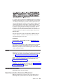
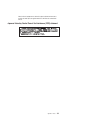
Importante:
Todas las declaraciones de precauciín de esta IBM documentation empiezan con
un número. Dicho número se emplea para establecer una referencia cruzada de
una declaraciín de precauciín o peligro en inglés con las versiones traducidas que
de dichas declaraciones pueden encontrarse en esta secciín.
Por ejemplo, si una declaraciín de peligro empieza con el número 1, las
traducciones de esta declaraciín de precauciín aparecen en esta secciín bajo
Declaraciín 1.
Lea atentamente todas las declaraciones de precauciín y peligro antes de llevar a
cabo cualquier operaciín.
Declaración 1
PELIGRO
La corriente eléctrica de los cables telefínicos, de alimentaciín y de comunicaciones es
perjudicial.
Para evitar una descarga eléctrica:
v No conecte ni desconecte ningún cable ni realice las operaciones de instalaciín,
mantenimiento o reconfiguraciín de este producto durante una tormenta.
v Conecte cada cable de alimentaciín a una toma de alimentaciín eléctrica con conexiín a
tierra y cableado correctos.
v Conecte a tomas de alimentaciín con un cableado correcto cualquier equipo que vaya a
estar conectado a este producto.
v Si es posible, utilice una sola mano cuando conecte o desconecte los cables de sent.al.
v No encienda nunca un equipo cuando haya riesgos de incendio, de inundaciín o de
daños estructurales.
v Desconecte los cables de alimentaciín, sistemas de telecomunicaciones, redes y mídems
conectados antes de abrir las cubiertas del dispositivo a menos que se indique lo
contrario en los procedimientos de instalaciín y configuraciín.
v Conecte y desconecte los cables tal como se describe en la tabla siguiente cuando
desee realizar una operaciín de instalaciín, de traslado o de apertura de las cubiertas
para este producto o para los dispositivos conectados.
146
Para la conexin
Para la desconexiín
1. APÁGUELO todo.
2. En primer lugar, conecte los cables a
los dispositivos.
3. Conecte los cables de señal a los
conectores.
4. Conecte cada cable de alimentaciín a la
toma de alimentaciín.
5. ENCIENDA el dispositivo.
1. APÁGUELO todo.
2. En primer lugar, retire cada cable de
alimentaciín de la toma de alimentaciín.
3. Retire los cables de señal de los
conectores.
4. Retire los cables de los dispositivos.
IntelliStation M Pro Types 6225 and 6228: Hardware Maintenance Manual and Troubleshooting Guide
Declaración 2
PRECAUCIÓN:
Cuando desee sustituir la batería de litio, utilice únicamente el número de pieza 33F8354 de
IBM o cualquier tipo de batería equivalente que recomiende el fabricante. Si el sistema
tiene un mídulo que contiene una batería de litio, sustitúyalo únicamente por el mismo tipo
de mídulo, que ha de estar creado por el mismo fabricante. La batería contiene litio y puede
explotar si el usuario no la utiliza ni la maneja de forma adecuada o si no se desprende de
la misma como corresponde.
No realice las acciones siguientes:
v Arrojarla al agua o sumergirla
v Calentarla a una temperatura que supere los 100°C (212°F)
v Repararla o desmontarla
Despréndase de la batería siguiendo los requisitos que exija el reglamento o la legislaciín
local.
Declaración 3
PRECAUCIÓN:
Cuando instale productos láser (como, por ejemplo, CD-ROM, unidades DVD, dispositivos
de fibra íptica o transmisores), tenga en cuenta las advertencias siguientes:
v No retire las cubiertas. Si retira las cubiertas del producto láser, puede quedar expuesto a
radiaciín láser perjudicial. Dentro del dispositivo no existe ninguna pieza que requiera
mantenimiento.
v El uso de controles o ajustes o la realizaciín de procedimientos que no sean los que se
han especificado aquí pueden dar como resultado una exposiciín perjudicial a las
radiaciones.
PELIGRO
Algunos productos láser contienen un diodo de láser incorporado de Clase 3A o de Clase
3B. Tenga en cuenta la advertencia siguiente.
Cuando se abre, hay radiaciín láser. No mire fijamente el rayo ni lleve a cabo ningún
examen directamente con instrumentos ípticos; evite la exposiciín directa al rayo.
Appendix B. Safety information
147
Declaración 4
≥18 kg
≥32 kg
≥55 kg
PRECAUCIÓN:
Tome medidas de seguridad al levantar el producto.
Declaración 5
PRECAUCIÓN:
El botín de control de alimentaciín del dispositivo y el interruptor de alimentaciín de la fuente
de alimentaciín no apagan la corriente eléctrica suministrada al dispositivo. Es posible
también que el dispositivo tenga más de un cable de alimentaciín. Para eliminar la corriente
eléctrica del dispositivo, asegúrese de desconectar todos los cables de alimentaciín de la
fuente de alimentaciín.
2
1
Declaración 10
PRECAUCIÓN:
No coloque ningún objeto que pese más de 82 kg (180 libras) encima de los dispositivos
montados en bastidor.
148
IntelliStation M Pro Types 6225 and 6228: Hardware Maintenance Manual and Troubleshooting Guide
Appendix C. Notices
This publication was developed for products and services offered in the U.S.A.
IBM may not offer the products, services, or features discussed in this document in
other countries. Consult your local IBM representative for information on the
products and services currently available in your area. Any reference to an IBM
product, program, or service is not intended to state or imply that only that IBM
product, program, or service may be used. Any functionally equivalent product,
program, or service that does not infringe any IBM intellectual property right may be
used instead. However, it is the user’s responsibility to evaluate and verify the
operation of any non-IBM product, program, or service.
IBM may have patents or pending patent applications covering subject matter
described in this document. The furnishing of this document does not give you any
license to these patents. You can send license inquiries, in writing, to:
IBM Director of Licensing
IBM Corporation
North Castle Drive
Armonk, NY 10504-1785
U.S.A.
INTERNATIONAL BUSINESS MACHINES CORPORATION PROVIDES THIS
PUBLICATION “AS IS” WITHOUT WARRANTY OF ANY KIND, EITHER EXPRESS
OR IMPLIED, INCLUDING, BUT NOT LIMITED TO, THE IMPLIED WARRANTIES
OF NON-INFRINGEMENT, MERCHANTABILITY OR FITNESS FOR A
PARTICULAR PURPOSE. Some jurisdictions do not allow disclaimer of express or
implied warranties in certain transactions, therefore, this statement may not apply to
you.
This information could include technical inaccuracies or typographical errors.
Changes are periodically made to the information herein; these changes will be
incorporated in new editions of the publication. IBM may make improvements and/or
changes in the product(s) and/or the program(s) described in this publication at any
time without notice.
Any references in this publication to non-IBM Web sites are provided for
convenience only and do not in any manner serve as an endorsement of those
Web sites. The materials at those Web sites are not part of the materials for this
IBM product, and use of those Web sites is at your own risk.
IBM may use or distribute any of the information you supply in any way it believes
appropriate without incurring any obligation to you.
Edition notice
© Copyright International Business Machines Corporation 2004. All rights
reserved.
U.S. Government Users Restricted Rights — Use, duplication, or disclosure
restricted by GSA ADP Schedule Contract with IBM Corp.
© Copyright IBM Corp. 2004
149
Trademarks
The following terms are trademarks of International Business Machines Corporation
in the United States, other countries, or both:
Active Memory
Active PCI
Active PCI-X
Alert on LAN
BladeCenter
C2T Interconnect
Chipkill
EtherJet
e-business logo
Eserver
FlashCopy
IBM
IBM (logo)
IntelliStation
NetBAY
Netfinity
NetView
OS/2 WARP
Predictive Failure
Analysis
PS/2
ServeRAID
ServerGuide
ServerProven
TechConnect
ThinkPad
Tivoli
Tivoli Enterprise
Update Connector
Wake on LAN
XA-32
XA-64
X-Architecture
XceL4
XpandOnDemand
xSeries
Intel, MMX, and Pentium are trademarks of Intel Corporation in the United States,
other countries, or both.
Microsoft, Windows, and Windows NT are trademarks of Microsoft Corporation in
the United States, other countries, or both.
UNIX is a registered trademark of The Open Group in the United States and other
countries.
Java and all Java-based trademarks and logos are trademarks of Sun
Microsystems, Inc. in the United States, other countries, or both.
Adaptec and HostRAID are trademarks of Adaptec, Inc., in the United States, other
countries, or both.
Linux is a trademark of Linus Torvalds in the United States, other countries, or both.
Red Hat, the Red Hat “Shadow Man” logo, and all Red Hat-based trademarks and
logos are trademarks or registered trademarks of Red Hat, Inc., in the United States
and other countries.
Other company, product, or service names may be trademarks or service marks of
others.
150
IntelliStation M Pro Types 6225 and 6228: Hardware Maintenance Manual and Troubleshooting Guide
Important notes
Processor speeds indicate the internal clock speed of the microprocessor; other
factors also affect application performance.
CD-ROM drive speeds list the variable read rate. Actual speeds vary and are often
less than the maximum possible.
When referring to processor storage, real and virtual storage, or channel volume,
KB stands for approximately 1000 bytes, MB stands for approximately 1 000 000
bytes, and GB stands for approximately 1 000 000 000 bytes.
When referring to hard disk drive capacity or communications volume, MB stands
for 1 000 000 bytes, and GB stands for 1 000 000 000 bytes. Total user-accessible
capacity may vary depending on operating environments.
Maximum internal hard disk drive capacities assume the replacement of any
standard hard disk drives and population of all hard disk drive bays with the largest
currently supported drives available from IBM.
Maximum memory may require replacement of the standard memory with an
optional memory module.
IBM makes no representation or warranties regarding non-IBM products and
services that are ServerProven®, including but not limited to the implied warranties
of merchantability and fitness for a particular purpose. These products are offered
and warranted solely by third parties.
IBM makes no representations or warranties with respect to non-IBM products.
Support (if any) for the non-IBM products is provided by the third party, not IBM.
Some software may differ from its retail version (if available), and may not include
user manuals or all program functionality.
Product recycling and disposal
This unit contains materials such as circuit boards, cables, electromagnetic
compatibility gaskets, and connectors which may contain lead and copper/beryllium
alloys that require special handling and disposal at end of life. Before this unit is
disposed of, these materials must be removed and recycled or discarded according
to applicable regulations. IBM offers product-return programs in several countries.
Information on product recycling offerings can be found on IBM’s Internet site at
http://www.ibm.com/ibm/environment/products/prp.shtml.
IBM encourages owners of information technology (IT) equipment to responsibly
recycle their equipment when it is no longer needed. IBM offers a variety of
programs and services to assist equipment owners in recycling their IT products.
Information on product recycling offerings can be found on IBM’s Internet site at
http://www.ibm.com/ibm/environment/products/prp.shtml.
Appendix C. Notices
151
Battery return program
This product may contain a sealed lead acid, nickel cadmium, nickel metal hydride,
lithium, or lithium ion battery. Consult your user manual or service manual for
specific battery information. The battery must be recycled or disposed of properly.
Recycling facilities may not be available in your area. For information on disposal of
batteries outside the United States, go to http://www.ibm.com/ibm/environment/
products/index.shtml or contact your local waste disposal facility.
In the United States, IBM has established a return process for reuse, recycling, or
proper disposal of used IBM sealed lead acid, nickel cadmium, nickel metal hydride,
and battery packs from IBM equipment. For information on proper disposal of these
batteries, contact IBM at 1-800-426-4333. Have the IBM part number listed on the
battery available prior to your call.
For Taiwan: Please recycle batteries.
For the European Union:
Notice: This mark applies only to countries within the European Union (EU).
Batteries or packaging for batteries are labeled in accordance with European
Directive 2006/66/EC concerning batteries and accumulators and waste batteries
and accumulators. The Directive determines the framework for the return and
recycling of used batteries and accumulators as applicable throughout the European
Union. This label is applied to various batteries to indicate that the battery is not to
be thrown away, but rather reclaimed upon end of life per this Directive.
Les batteries ou emballages pour batteries sont étiquetés conformément aux
directives européennes 2006/66/EC, norme relative aux batteries et accumulateurs
en usage et aux batteries et accumulateurs usés. Les directives déterminent la
marche à suivre en vigueur dans l’Union Européenne pour le retour et le recyclage
des batteries et accumulateurs usés. Cette étiquette est appliquée sur diverses
batteries pour indiquer que la batterie ne doit pas être mise au rebut mais plutôt
récupérée en fin de cycle de vie selon cette norme.
152
IntelliStation M Pro Types 6225 and 6228: Hardware Maintenance Manual and Troubleshooting Guide
In accordance with the European Directive 2006/66/EC, batteries and accumulators
are labeled to indicate that they are to be collected separately and recycled at end
of life. The label on the battery may also include a chemical symbol for the metal
concerned in the battery (Pb for lead, Hg for mercury, and Cd for cadmium). Users
of batteries and accumulators must not dispose of batteries and accumulators as
unsorted municipal waste, but use the collection framework available to customers
for the return, recycling, and treatment of batteries and accumulators. Customer
participation is important to minimize any potential effects of batteries and
accumulators on the environment and human health due to the potential presence
of hazardous substances. For proper collection and treatment, contact your local
IBM representative.
This notice is provided in accordance with Royal Decree 106/2008 of Spain: The
retail price of batteries, accumulators, and power cells includes the cost of the
environmental management of their waste.
For California:
Perchlorate material – special handling may apply. See http://www.dtsc.ca.gov/
hazardouswaste/perchlorate/.
The foregoing notice is provided in accordance with California Code of Regulations
Title 22, Division 4.5 Chapter 33. Best Management Practices for Perchlorate
Materials. This product/part may include a lithium manganese dioxide battery which
contains a perchlorate substance.
Monitor
New Jersey: For information about recycling covered electronic devices in the state
of New Jersey, go to the New Jersey Department of Environmental Protection Web
site at http://www.state.nj.us/dep/dshw/recycle/Electronic_Waste/index.html.
Oregon: For information about recycling covered electronic devices in the state of
Oregon, go to the Oregon Department of Environmental Quality Web site at
http://www.deq.state.or.us/lq/electronics.htm.
Washington: For information about recycling covered electronic devices in the state
of Washington, go to the Department of Ecology Web site at http://www.ecy.wa.gov/
programs/swfa/eproductrecycle/ or telephone the Washington Department of
Ecology at 1-800-RECYCLE (1-800-732-9253).
Electronic emission notices
IBM IntelliStation M Pro Types 6225 and 6228
Federal Communications Commission (FCC) statement
Note: This equipment has been tested and found to comply with the limits for a
Class B digital device, pursuant to Part 15 of the FCC Rules. These limits are
Appendix C. Notices
153
designed to provide reasonable protection against harmful interference in a
residential installation. This equipment generates, uses, and can radiate radio
frequency energy and, if not installed and used in accordance with the instructions,
may cause harmful interference to radio communications. However, there is no
guarantee that interference will not occur in a particular installation. If this
equipment does cause harmful interference to radio or television reception, which
can be determined by turning the equipment off and on, the user is encouraged to
try to correct the interference by one or more of the following measures:
v Reorient or relocate the receiving antenna.
v Increase the separation between the equipment and receiver.
v Connect the equipment into an outlet on a circuit different from that to which the
receiver is connected.
v Consult an IBM authorized dealer or service representative for help.
Properly shielded and grounded cables and connectors must be used in order to
meet FCC emission limits. Proper cables and connectors are available from IBM
authorized dealers. IBM is not responsible for any radio or television interference
caused by using other than recommended cables and connectors or by
unauthorized changes or modifications to this equipment. Unauthorized changes or
modifications could void the user’s authority to operate the equipment.
This device complies with Part 15 of the FCC Rules. Operation is subject to the
following two conditions: (1) this device may not cause harmful interference, and (2)
this device must accept any interference received, including interference that may
cause undesired operation.
Responsible party:
International Business Machines Corporation
New Orchard Road
Armonk, NY 10504
Telephone: 1-919-543-2193
Tested To Comply
With FCC Standards
FOR HOME OR OFFICE USE
Industry Canada Class B emission compliance statement
This Class B digital apparatus complies with Canadian ICES-003.
Avis de conformité à la réglementation d’Industrie Canada
Cet appareil numérique de la classe B est conforme à la norme NMB-003 du
Canada.
European Union EMC Directive conformance statement
This product is in conformity with the protection requirements of EU Council
Directive 89/336/EEC on the approximation of the laws of the Member States
relating to electromagnetic compatibility. IBM cannot accept responsibility for any
failure to satisfy the protection requirements resulting from a nonrecommended
modification of the product, including the fitting of non-IBM option cards. This
product has been tested and found to comply with the limits for Class B Information
Technology Equipment according to CISPR 22/European Standard EN 55022. The
154
IntelliStation M Pro Types 6225 and 6228: Hardware Maintenance Manual and Troubleshooting Guide
limits for Class B equipment were derived for typical residential environments to
provide reasonable protection against interference with licensed communication
devices.
Japanese Voluntary Control Council for Interference (VCCI) statement
Appendix C. Notices
155
Power cords
For your safety, IBM provides a power cord with a grounded attachment plug to use
with this IBM product. To avoid electrical shock, always use the power cord and
plug with a properly grounded outlet.
IBM power cords used in the United States and Canada are listed by Underwriter’s
Laboratories (UL) and certified by the Canadian Standards Association (CSA).
For units intended to be operated at 115 volts: Use a UL-listed and CSA-certified
cord set consisting of a minimum 18 AWG, Type SVT or SJT, three-conductor cord,
a maximum of 15 feet in length and a parallel blade, grounding-type attachment
plug rated 15 amperes, 125 volts.
For units intended to be operated at 230 volts (U.S. use): Use a UL-listed and
CSA-certified cord set consisting of a minimum 18 AWG, Type SVT or SJT,
three-conductor cord, a maximum of 15 feet in length and a tandem blade,
grounding-type attachment plug rated 15 amperes, 250 volts.
For units intended to be operated at 230 volts (outside the U.S.): Use a cord set
with a grounding-type attachment plug. The cord set should have the appropriate
safety approvals for the country in which the equipment will be installed.
IBM power cords for a specific country or region are usually available only in that
country or region.
156
IBM power cord part
number
Used in these countries and regions
02K0546
China
13F9940
Australia, Fiji, Kiribati, Nauru, New Zealand, Papua New Guinea
13F9979
Afghanistan, Albania, Algeria, Andorra, Angola, Armenia, Austria,
Azerbaijan, Belarus, Belgium, Benin, Bosnia and Herzegovina,
Bulgaria, Burkina Faso, Burundi, Cambodia, Cameroon, Cape
Verde, Central African Republic, Chad, Comoros, Congo
(Democratic Republic of), Congo (Republic of), Cote D’Ivoire
(Ivory Coast), Croatia (Republic of), Czech Republic, Dahomey,
Djibouti, Egypt, Equatorial Guinea, Eritrea, Estonia, Ethiopia,
Finland, France, French Guyana, French Polynesia, Germany,
Greece, Guadeloupe, Guinea, Guinea Bissau, Hungary, Iceland,
Indonesia, Iran, Kazakhstan, Kyrgyzstan, Laos (People’s
Democratic Republic of), Latvia, Lebanon, Lithuania, Luxembourg,
Macedonia (former Yugoslav Republic of), Madagascar, Mali,
Martinique, Mauritania, Mauritius, Mayotte, Moldova (Republic of),
Monaco, Mongolia, Morocco, Mozambique, Netherlands, New
Caledonia, Niger, Norway, Poland, Portugal, Reunion, Romania,
Russian Federation, Rwanda, Sao Tome and Principe, Saudi
Arabia, Senegal, Serbia, Slovakia, Slovenia (Republic of),
Somalia, Spain, Suriname, Sweden, Syrian Arab Republic,
Tajikistan, Tahiti, Togo, Tunisia, Turkey, Turkmenistan, Ukraine,
Upper Volta, Uzbekistan, Vanuatu, Vietnam, Wallis and Futuna,
Yugoslavia (Federal Republic of), Zaire
13F9997
Denmark
14F0015
Bangladesh, Lesotho, Maceo, Maldives, Namibia, Nepal,
Pakistan, Samoa, South Africa, Sri Lanka, Swaziland, Uganda
IntelliStation M Pro Types 6225 and 6228: Hardware Maintenance Manual and Troubleshooting Guide
IBM power cord part
number
Used in these countries and regions
14F0033
Abu Dhabi, Bahrain, Botswana, Brunei Darussalam, Channel
Islands, China (Hong Kong S.A.R.), Cyprus, Dominica, Gambia,
Ghana, Grenada, Iraq, Ireland, Jordan, Kenya, Kuwait, Liberia,
Malawi, Malaysia, Malta, Myanmar (Burma), Nigeria, Oman,
Polynesia, Qatar, Saint Kitts and Nevis, Saint Lucia, Saint Vincent
and the Grenadines, Seychelles, Sierra Leone, Singapore, Sudan,
Tanzania (United Republic of), Trinidad and Tobago, United Arab
Emirates (Dubai), United Kingdom, Yemen, Zambia, Zimbabwe
14F0051
Liechtenstein, Switzerland
14F0069
Chile, Italy, Libyan Arab Jamahiriya
14F0087
Israel
1838574
Antigua and Barbuda, Aruba, Bahamas, Barbados, Belize,
Bermuda, Bolivia, Brazil, Caicos Islands, Canada, Cayman
Islands, Costa Rica, Colombia, Cuba, Dominican Republic,
Ecuador, El Salvador, Guam, Guatemala, Haiti, Honduras,
Jamaica, Japan, Mexico, Micronesia (Federal States of),
Netherlands Antilles, Nicaragua, Panama, Peru, Philippines,
Taiwan, United States of America, Venezuela
24P6858
Korea (Democratic People’s Republic of), Korea (Republic of)
34G0232
Japan
36L8880
Argentina, Paraguay, Uruguay
49P2078
India
49P2110
Brazil
6952300
Antigua and Barbuda, Aruba, Bahamas, Barbados, Belize,
Bermuda, Bolivia, Caicos Islands, Canada, Cayman Islands,
Colombia, Costa Rica, Cuba, Dominican Republic, Ecuador, El
Salvador, Guam, Guatemala, Haiti, Honduras, Jamaica, Mexico,
Micronesia (Federal States of), Netherlands Antilles, Nicaragua,
Panama, Peru, Philippines, Saudi Arabia, Thailand, Taiwan,
United States of America, Venezuela
Appendix C. Notices
157
158
IntelliStation M Pro Types 6225 and 6228: Hardware Maintenance Manual and Troubleshooting Guide
Index
Numerics
1394 (FireWire)
connector location
rear panel 79
A
acoustical noise emissions 3
adapter
considerations 39
full length 39
IEEE 1394 (FireWire) 39
installing 39
PCI 39
PCI bus 39
SCSI 43
specifications 3
attention statements, defined 2
audio
connectors 62
B
battery
location 78
replacement 57
battery return program 152
bays
2, 3, and 4 48
5 50
drive 47
filler panel 48
beep codes 10
beep symptoms 83
bezel, removing 34
bi-directional parallel port configuration 63
BIOS code, updating 22
Broadcom NetXtreme Gigabit Ethernet Boot Agent
general 7
built-in self-test 101
bus fault messages 101
C
cable connectors
external 79
internal 78
cables
internal drives 53
power 53
power and signal 53
signal 53
USB 65
cabling
Ethernet 62
SCSI adapter 43
SCSI requirements 64
© Copyright IBM Corp. 2004
cabling (continued)
system board connectors
external 79
internal 78
caution statements, defined 2
CD-ROM drive
eject button 4
installing 47
problems 88
removing 45
specifications 3
CD-RW drive
installing 47
removing 45
channels, SCSI 64
chart, troubleshooting 15
checkout
general 9
procedure 10
clearing CMOS 20
CMOS
clear jumper 20
clearing 20
component locations, system board
adapters, PCI 77
battery 78
external connectors 79
internal connectors 78
memory 77
microprocessor 77
option connectors 77
components
major 31
configuration
Configuration/Setup Utility 7
configuration programs
Broadcom NetXtreme Gigabit Ethernet Boot
Agent 7
SCSISelect Utility program 7
Configuration/Setup Utility program 7, 8
connecting
external options 60
connector
audio 62
DVI monitor pin-assignments 66
serial 64
serial port pin-assignments 64
universal serial bus (USB) 65
video 65
connector locations
1394 (FireWire), rear panel 79
audio, rear panel 79
diskette drive 78
Ethernet 79
external ports 79
fans 78
hard disk drive
SATA 78
159
connector locations (continued)
hard disk drive (continued)
SCSI 78
IDE drive 78
internal cable 78
keyboard 79
mouse 79
parallel 79
SCSI daughter card connector 78
serial 79
system board options 77
USB, rear panel 79
connectors
IEEE 1394 (FireWire) 63
input/output 61
serial ATA 47
Ultra320 SCSI 64
controller
SCSI 43
cooling 3
cover
removing 32
cover, replacing 33
creating an emergency recovery diskette
Red Hat Linux 19
Windows 19
CRU tier levels 107
CRUs, defined iii, 107
customer replacement units 29
D
danger statements, defined 2
device drivers
recovering 16
Device Drivers CD 16
diagnostic
error codes 85
error messages 12
programs 12, 13
programs and error messages
test log 13
text messages 12
tools 10
viewing test log 13
diagnostics
creating a diskette 17
downloading 17
using a diskette 18
DIMM connector
installing memory 54
locations 54
DIMM retaining clips 55
DIMMs
slot locations 77
diskette
drive activity LED 4
eject button 4
IBM Enhanced Diagnostics
using 18
recovery-repair 20
160
12
diskette (continued)
Red Hat Linux 19
Windows 19
diskette drive
installing 47, 48, 50
problems 88
display problems 90
disposal of monitor 153
drive
bay filler panel 48
cage 50
installation 48, 50
drives
installing 47
E
electrical input 3
environment 3
error codes
SCSI 98
error codes, diagnostic 85
error codes, POST 95
error LEDs, system board 79
error messages
diagnostic 12
fan 99
power 99
small computer systems interface (SCSI)
temperature 98
error symptoms 87
error, diagnostic code format 12
Ethernet
cabling 62
connector pin-number assignments 62
pin-number assignment 62
port 62
Ethernet controller
troubleshooting 26
expansion bays
location 47
type 47
external connectors, system board 79
external options
connecting 60
F
fan
error messages 99
fan assembly, microprocessor
removing 35
replacing 36
fan connectors, system board 78
features and specifications, server 3
filler panel 48
FireWire
See 1394 (FireWire)
front I/O panel
removing 44
replacing 44
IntelliStation M Pro Types 6225 and 6228: Hardware Maintenance Manual and Troubleshooting Guide
11
FRUs, defined
K
iii, 107
keyboard
problems
H
handling static-sensitive devices 29
hard disk drive
checkout 101
installing 47
hardware problems 10
hardware, major components 106
heat output 3
heat sink, microprocessor
removing 68
replacing 72
L
LEDs 4
activity 4, 5
system board
79
M
major components 31
memory
installing 54
modules 54
problems 90
slot locations 77
memory module
order of installation 54
supported 54
memory module, specifications 3
memory modules
specifications 3
messages
diagnostic error 12
diagnostic text 12
small computer systems interface (SCSI) error
microprocessor
problems 90
removing 68
replacing 72
specifications 3
microprocessor specifications 3
monitor problems 90
monitor, disposal of 153
mother board
See system board
mouse
connector pin-assignments 62
port 62
mouse problems 89
I
IDs, setting SCSI 64
IEEE 1394 (FireWire) adapter 39
IEEE 1394 (FireWire) connectors 63
IEEE 1394 FireWire
See 1394 (FireWire)
important statements, defined 2
indicators and controls 4
installation order, memory modules 54
installing
See also removing/replacing
adapters 39
battery 57
cover 33
device drivers 16
drive in bays 2, 3, or 4 48
internal drives 47
memory modules 54
options 29
security rope clip 59
installing drives
bay 5 50
intermittent problems 89
internal
drive bays 47
drives, installing 47
internal connectors, system board 78
internal drive bay, rotating 73
internal drive cage, rotating 73
internal speaker
removing 56
replacing 56
11
N
network connection problems
no-beep
symptoms 85
notes, important 151
notices
book 2
notices, types of 2
J
jumper
boot block recovery 23
IEEE 1394 (FIreWire) enable/disable
password 21
jumpers 80
89
26
25
O
online
publications 1
support iv
operating system, recovering 15
option connectors, system board 77
Index
161
option problems 93
order of installation, memory modules
54
P
parallel port
connector 63
connector pin-assignments 63
parts listing 105
password
erasing lost or forgotten 20
jumper 21
PC-Doctor
for Windows 15
PCI
adapters 39
expansion slots 3
PCI expansion slots 3
PCI, slot locations 77
pin-assignments
video 66
pin-number assignments, Ethernet 62
pointing device problems 89
port
Ethernet 62
port, Ethernet 62
ports
See also connectors
input/output 61
universal serial bus (USB) 65
POST error codes 95
power
checkout 25
control button 5
cords 111
error messages 99
problems 93
power control panel, removing/replacing
power supply
removing 74
replacing 75
power supply specifications 3
power switch/LED assembly
removing 76
replacing 76
power-on LED 4, 5
power-on self-test (POST)
beep codes 11
error log 11
error messages 10
problem determination 103
problems
CD-ROM drive 88
diskette drive 88
hardware 10
intermittent 89
keyboard 89
memory 90
microprocessor 90
monitor 90
mouse 89
162
problems (continued)
option 93
pointing device 89
power 93
serial port 94
software 94
undetermined 102
USB port 89, 94
R
76
recovering
device drivers 16
operating system 15
POST/BIOS update failure 23
preinstalled software 15
Recovery CD 110
recovery repair diskette
creating 18
recovery-repair diskette 20
Remote Supervisor Adapter II
configuration 7
removable media drives, installing 47
removing
bezel 34
side cover 32
removing/replacing
CD-ROM drive 45
CD-RW drive 45
cover 33
front I/O panel 44
heat sink 68
internal speaker 56
microprocessor 68
microprocessor fan assembly 35
power supply 74
power switch/LED assembly 76
SCSI daughter card 37
system board 81
replacement units 29
replacing
battery 57
retaining clips, DIMM 55
rope clip
installing for security 59
rotating internal drive cage 73
S
SCSI connector
description 64
SCSI controller cabling 43
SCSI daughter card
connector location 78
removing 37
replacing 38
security
rope clip 59
serial
connector pin-assignments
port problems 94
64
IntelliStation M Pro Types 6225 and 6228: Hardware Maintenance Manual and Troubleshooting Guide
side cover, removing 32
size 3
small computer system interface (SCSI)
error codes 98
small computer systems interface (SCSI)
cabling requirements 64
error messages 11
setting IDs 64
software
problems 94
specifications and features 3
starting
diagnostic programs 12, 13
starting the computer 5
statements, types of 2
static electricity 29
static-sensitive devices, handling 29
symptoms
beep 83
no-beep 85
symptoms 87
system
shutdown 100
temperature related 100
system board
connectors
SCSI 64
external connectors 79
internal connectors 78
jumpers 80
LEDs 79
option connectors 77
removing 81
replacing 82
system reliability 29
system specifications 3
Universal serial bus (USB) problems 89, 94
updating BIOS code 22
USB connector locations
rear 79
using
Enhanced Diagnostics diskette 18
Product Recovery program 15
recovery-repair diskette
Windows 20
using the Configuration/Setup Utility program 7
V
video 3
connector 65
DVI connector 66
DVI connector pin-assignments
video controller 3
specifications 3
66
W
weight
3
T
tape drive, installing 47
temperature 3
temperature error messages 98
test log
viewing diagnostic 13
test log, viewing diagnostic 13
thermal grease, heat sink
handling 69
tier levels, CRU 107
trademarks 150
troubleshooting chart 15
turning off
the computer 6
U
Ultra320 SCSI connector 64
undetermined problems 102
universal serial bus (USB)
cables 65
connectors 65
ports 65
Index
163
164
IntelliStation M Pro Types 6225 and 6228: Hardware Maintenance Manual and Troubleshooting Guide
Part Number: 25K8120
Printed in USA
(1P) P/N: 25K8120