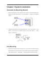
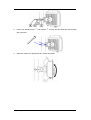
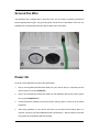
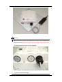
1
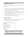
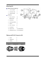
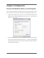
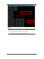
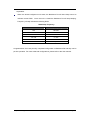
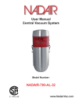
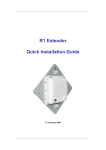
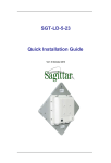
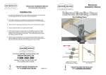
Backbone R2
Quick Installation Guide
V 2.1.15 July 2010
Chapter 1 Introduction
Page 1
Copyright
Copyright © 2010 all rights reserved. No part of this publication may be reproduced, adapted,
stored in a retrieval system, translated into any language, or transmitted in any form or by any
means without the written permission of the supplier.
About the Installation Guide
This Installation Guide is intended to guide professional installer to install the Backbone R2. It
includes procedures to assist you in avoiding unforeseen problems.
Conventions
Warning:
This indicates a warning or caution that you have to abide.
Note:
This indicates an important note that you must pay attention to.
Chapter 1 Introduction
Page 2
Chapter 1 Introduction
Introduction
The Backbone R2 is a high-performance outdoor-deployable wireless bridge that provides
wireless connectivity among multiple network locations. It supports Base Station, CPE, PTP and
PTMP connectivity. Moreover, the Backbone R2 has a built-in 23dBi planar antenna that can
deliver up to a 40Km connection. An external antenna may also be used to improve signal
quality, extend distance and flexible for local coverage applications. With high throughput and
long-distance transmission, the Backbone R2 is an ideal backhaul solution for Carriers, Service
Providers and Enterprises!
Chapter 1 Introduction
Page 3
Chapter 2 Preparation before Installation
This chapter describes safety precautions and product information you have to know and check
before installing Backbone R2.
Professional Installation Required
1. Please seek assistance from a professional installer who is well trained in the RF installation
and knowledgeable in the local regulations.
2. The Backbone R2 is distributed through distributor and system installer with professional
technicians and will not be sold directly through retail store.
Safety Precautions
To keep you safe and install the hardware properly, please read and follow these safety
precautions.
1.
If you are installing an antenna for the first time, for your safety as well as others’, please
seek assistance from a professional installer who has received safety training on the
hazards involved.
2.
Keep safety as well as performance in mind when selecting your installation site, especially
where there are electric power and phone lines.
3.
4.
When installing your antenna, note the following:
♦
Do not use a metal ladder;
♦
Do not work on a wet or windy day;
♦
Wear shoes with rubber soles and heels, rubber gloves, long sleeved shirt or jacket.
When the system is operational, avoid standing directly in front of the antenna. Strong RF
fields are present when the transmitter is on.
Chapter 2 Preparation before Installation
Page 4
Installation Precautions
To keep the Backbone R2 well while you are installing it, please read and follow these installation
precautions.
1. Users MUST use a proper and well-installed surge arrestor and grounding kit with Backbone
R2; otherwise, a random lightening could easily cause fatal damage to Backbone R2.
EMD
(Lightning) DAMAGE IS NOT COVERED UNDER WARRNTY.
2. Make sure PoE is correctly connected to the RJ-45 port on the Backbone R2 labeled
PoE+Data.
DO NOT CONNECT TO THE PORT LABELED “Warning!! No POE”,
otherwise the extender will be severely damaged!
3. Users MUST power off the Backbone R2 first before connecting the external antenna to it;
otherwise, damage might be caused to the Backbone R2 itself.
Product Package
The product package you have received should contain the following items. If any of them are
not included or damaged, please contact your local vendor for support.
Backbone R2 with integrated 23dBi antenna
×1
Mounting Kit
×1
PoE Injector & Power cord
×1
Grounding Wire w/ screw
×1
Water Proof RJ-45 Connector Kit
×1
Quick Installation Guide
×1
Product CD
×1
Note:
Product CD contains Management Tool, Quick Installation Guide and User
Manual!
Chapter 2 Preparation before Installation
Page 5
Mounting Kit
Wall/Pole Mounting Bracket
1.
T-Form Bracket
×1
2.
Articulation Pole
×1
3.
Pole Mount Bar
×1
Fasteners
4.
M8×80 Screw … ×2
M8X90 Screw
X1
×3
5.
M8 Washer
6.
M8 Spring Washer ×3
7.
M8 Nut
×1
8.
M5×16 Screw
×4
9.
M5 Washer
×4
10. Wood Screw
×4 (for Wall Mount)
11. Wall/Gyprock Plug ×4 (for Wall Mount)
Waterproof RJ-45 Connector Kit
1.
Gland
×1
2.
Sealing Nut
×1
3.
Sealing
×1
Chapter 2 Preparation before Installation
Page 6
Chapter 3 System Installation
Assemble the Mounting Bracket
1.
Place the main bracket into the seating and use a spanner to fasten the bracket to the
8 and M5 washers ○
9 provided in the hardware
Backbone R2 with M5×16 screws ○
packets;
2.
2 to the T-form bracket ○
1 via a
Assemble the main bracket by placing articulation pole ○
4 screw through the insertion axe and fix with the M8 washer ○
5 , spring
M8×90 ○
6 and M8 nut○
7 ;
washer ○
Pole Mounting
1.
3 over the top of the pole by securing
Install the main bracket and the pole mount bar ○
4
the drill holes of the pole mount bar to the main bracket ones and insert two M8×80 ○
6 and washers ○
5 through the drill holes and main bracket;
screws, spring washers ○
Chapter 3 System Installation
Page 7
2.
4 and washers ○
5 through the drill holes and main bracket
Fasten two M8×80 screws ○
with a spanner;
3.
Adjust the antenna for appropriate tilt / vertical orientation.
Chapter 3 System Installation
Page 8
Connect Up
Before installing the Ethernet cable with a waterproof RJ-45 connector, it is recommended that
the Cat-5 RJ-45 coaxial cable be used for the bridge to power injector connections.
1.
To connect to the hole labeled PoE+Data, open the black cover in advance by using a
coin or a slotted screwdriver and then screw in the body of the gland and tighten.
2.
Slide the sealing nut to the RJ-45 cable from its middle breach and then insert the sealing
into the cable.
Slide the Sealing Nut from its Breach
3.
Insert the RJ-45 connector and make sure that the locking tab snaps home.
Backbone R2 RJ-45 Port
4.
Screw the sealing on the gland and tighten.
Chapter 3 System Installation
Page 9
Ground the Wire
The Backbone R2 is shipped with a grounding wire. The unit must be properly grounded to
protect against power surges. The grounding point can be found on the bottom of the unit. It is
supplied with an appropriate grounding lug for attachment to the ODU.
Power On
To power up the Backbone R2, follow the steps bellow:
1.
Plug a user-supplied Cat-5 Ethernet cable from your wired LAN (or a computer) into the
power injector RJ-45 jack (DATA IN);
2.
Plug a user-supplied Cat-5 Ethernet cable from the Backbone R2 into the power injector
RJ-45 jack (P+DATA OUT);
3.
Connect the power module to the power injector and plug the AC cord into an AC power
receptacle.
4.
After being powered on, the device will send out the beep sound lasting about 1.5
seconds, informing you that the Backbone R2 is powered up! Wait for about 60 seconds
the system will be initialized and start working.
Chapter 3 System Installation
Page 10
Warning:
Make sure PoE is correctly connected to the RJ-45 port on the Backbone R2
labeled PoE+Data. DO NOT connect to the port labeled “Warning!! No POE”,
otherwise the extender will be severely damaged!
z
When install the secondary antenna, please make sure power off the device
to prevent unexpected damage.
Chapter 3 System Installation
Page 11
Chapter 4 Configuration
Connect the Backbone R2 to a Local Computer
If you are configuring the Backbone R2 locally (without connecting its power injector to a wired
LAN), connect a PC to the power injector’s Ethernet port using a Category 5 Ethernet cable.
1.
Assign a static IP address to your PC which is in the same network segment with the
Backbone R2. As the default IP address of this unit is 192.168.1.1, you may choose from
192.168.1.2 to 192.168.1.254.
2.
Test the link status between your PC and the Backbone R2. Start a command prompt and
execute a continuous ping command “ping 192.168.1.1 –t”. If ping to the wireless bridge is
successful (as shown below), open Internet browser and enter the bridge’s IP address in
the address filed and press Enter.
Chapter 4 Configuration
Page 12
Backbone R2’s still initializing
System ready
Note:
Considering convenient configuration, it is recommended to configure local
and remote Backbone R2 respectively on two computers.
z
TTL time may vary depending on the operating system..
Chapter 4 Configuration
Page 13
How to Establish Wireless Bridge Mode
The Backbone R2 supports four operating modes, which are Base Station, CPE, Peer-to-Peer
(CSMA) and Peer-to-Peer (TDMA). Normally, Wireless Bridge is the typical mode on this unit.
Here we will illustrate how to establish wireless bridge connectivity with Backbone R2.
Enter the user name (admin) and password (password) to login and make configurations.
Note:
Due to browser’s security trusted sites, 192.168.1.1 might not able to be opened.
You may choose to continue to the website.
Open “Basic Setup” in “System”, set the IP address of two Backbone R2s in the same
network segment. e.g. local Backbone R2 as 192.168.1.1 and remote Backbone R2 as
192.168.1.2 and set the IP Subnet Mask on both as 255.255.255.0
Chapter 4 Configuration
Page 14
Warning:
Each IP address is unique within a LAN, otherwise IP collision may occur!
Open “Radio” in “Wireless” and you will find the default operating mode is Peer-to-Peer
(CSMA). Select RF1 (WLAN1) or RF2 (WLAN2) as Bridge to make the following
configuration. Here we take RF1 as an example. Select Peer-to-Peer (CSMA) operating
mode and keep the Channel/Frequency and Bandwidth on both Backbone R2s identical.
Click “Apply” to save settings.
Chapter 4 Configuration
Page 15
Login the Web-based interface of remote Backbone R2, open “About” in “System” and
record the wireless MAC address of it, either WLAN 1 or WLAN 2 MAC Address.
Login the Web-based interface of local Backbone R2 and open “Peer-to-Peer Setup” in
“Wireless”. Select “RF1” , input the WLAN1 or WLAN2 MAC address of the remote one to
“Remote MAC Address 1” field and click “Apply”;
Warning:
The MAC address on the housing of Backbone R2 is the ETH MAC address;
therefore it can not be used in Peer-to-Peer links.
The IP address of your PC should be in the same network segment to the one
of bridges.
Chapter 4 Configuration
Page 16
Use ping to check whether the link between the two Backbone R2 is OK.
Backbone R2 A
Backbone R2 B
To get a better wireless connectivity, antenna alignment is strongly recommended after
both Backbone R2s are installed long distance apart.
Login the Web-based interface of the local Backbone R2 and open “Peer-to-Peer Setup”
in “Wireless”. Select RF1 and hit “Align Antenna” button, an antenna alignment tool will
popup. Specify the Target RSSI and click “Start” to begin the antenna alignment.
Fix the local antenna and adjust the remote antenna elevation and horizontal direction.
During the adjustment, observe “Current RSSI” in local Backbone R2. Fix the remote
antenna when it reaches your expectation. Usually, RSSI between -60 and -70dBm
indicates rather good signal strength.
Adjust the local antenna after fixing the remote one. During the adjustment, observe
“Current RSSI” in the remote Backbone R2. Fix the local antenna when it reaches your
Chapter 4 Configuration
Page 17
expectation.
When the antenna alignment tool starts, the Backbone R2 will issue beep sound to
indicate current RSSI. Once the tool is closed the Backbone R2 will stop beeping.
Frequency of beep indicate the following RSSI:
RSSI-Beep Frequency
RSSI
Beep Frequency
>-50
100 /sec
-50~-60
50 /sec
-60~-70
5 /sec
-70~-80
2 / sec
-80~-90
1 /sec
< -90
No beep sound
Congratulations! You have primarily completed configuration on Backbone R2 and they can be
put into operation. For more advanced configurations, please refer to the User manual.
Chapter 4 Configuration
Page 18
Chapter 5 Troubleshooting
This chapter provides troubleshooting procedures for basic problems with the Backbone R2.
Q 1. What if my Backbone R2 fails to connect to the remote one?
•
Ethernet Link: Check the availability of power to the bridge by observing the LED
status on the power injector.
-
Green: The Backbone R2 is connecting to the backhaul network.
-
Off: The Backbone R2 disconnects from the wired network, check whether the power
cord and Ethernet cables to the network and bridge are correctly connected.
•
Basic Configurations: Mismatched basic settings among bridges are the most
common cause of connectivity fail. If the bridge does not associate with a remote
bridge, check whether in each device are identical.
•
Security Settings: Remote bridges attempting to authenticate to your Backbone R2
must support the same security options configured in your bridge, such as WEP and
WPA (2)-PSK. If your bridge fails to associate with others, check whether the security
settings are the same as your bridge settings.
•
Antenna Alignment: If the methods above are all checked to be correct, you can
observe and verify antenna alignment with RSSI value.
Q 2. What if I would like to reset the unit to default settings?
You may restore factory default settings in “Backup/Restore Settings” from “Management”
Q 3. What if I would like to backup and restore my configuration settings?
You may do the backup by generating a configuration file or retrieve the settings you have
backed up previously in “Backup/Restore Settings” from “Management”
Chapter 5 Troubleshooting
Page 19