1
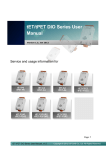
WF-2000 Series Wi-Fi I/O Module User’s Manual www.icpdas.com WF-2000 Series Wi-Fi I/O User’s Manual (Ver. 1.0, Sep./2012) ------------- 1 Warranty All products manufactured by ICP DAS are under warranty regarding defective materials for a period of one year from the date of delivery to the original purchaser. Warning ICP DAS assumes no liability for damages resulting from the use of this product. ICP DAS reserves the right to change this manual at any time without notice. The information furnished by ICP DAS is believed to be accurate and reliable. However, no responsibility is assumed by ICP DAS for its use, or for any infringements of patents or other rights of third parties resulting from its use. Copyright Copyright 2012 by ICP DAS. All rights are reserved. Trademark The names used for identification only may be registered trademarks of their respective companies. Document Revision Version 1.0 Author T.H. Date 2012-09-20 Description of changes First Release Revision WF-2000 Series Wi-Fi I/O User’s Manual (Ver. 1.0, Sep./2012) ------------- 2 Table of Contents 1. Introduction .......................................................................................5 1.1 1.2 Wireless connection mode ................................................................. 5 Features............................................................................................. 5 1.2.1 1.3 Features Description ........................................................................ 6 Specifications ..................................................................................... 8 2. Hardware .........................................................................................11 2.1 Front Panel .......................................................................................11 2.2 2.3 2.4 Top Panel ......................................................................................... 13 Dimensions ...................................................................................... 14 Hardware Connection ...................................................................... 15 Power and Serial port connection .................................................. 15 2.4.1 2.4.2 I/O connection ................................................................................ 15 Watchdog Timer Settings ................................................................. 18 FW / OP Dip-switch.......................................................................... 18 2.6.1 2.6.2 Firmware Update Mode.................................................................. 18 Firmware Operation Mode.............................................................. 21 2.5 2.6 3. Software...........................................................................................22 3.1 3.2 Connection and Configuration Tool – WF-2000 I/O Utility ................ 22 WF-2000 I/O Utility........................................................................... 23 Main Screen ................................................................................... 23 Basic Parameter configuration ....................................................... 27 Net ID............................................................................................... 27 Network configuration ...................................................................... 28 Wi-Fi configuration ........................................................................... 28 Parameter Transmission Interface ................................................... 29 Parameter Transmission status bar.................................................. 30 Display Firmware Information .......................................................... 30 Parameter reading function.............................................................. 30 Parameter writing function ............................................................... 30 Exit parameter setting ...................................................................... 31 3.2.1 3.2.2 3.2.3 3.2.4 Pair Connection Settings Screen ................................................... 31 DO Value Settings Screen.............................................................. 33 4. Application Notes............................................................................34 4.1 4.2 Hardware Installation ....................................................................... 35 WF-2000 series connection setting.................................................. 35 4.2.1 4.2.2 WF-2000 Series Connection Configuration .................................... 35 PC Connection Configuration......................................................... 37 WF-2000 Series Wi-Fi I/O User’s Manual (Ver. 1.0, Sep./2012) ------------- 3 4.2.3 4.2.4 PC Connection Test........................................................................ 39 Pair Connection Test ...................................................................... 42 5. Modbus Applications ......................................................................45 5.1 What is Modbus TCP/IP?................................................................. 45 5.2 Protocol Description......................................................................... 45 MBAP ............................................................................................. 46 Function Code................................................................................ 46 Data................................................................................................ 47 5.2.1 5.2.2 5.2.3 5.2.4 5.2.5 5.3.1 Response ....................................................................................... 47 Data Encoding................................................................................ 48 Address Mapping ............................................................................. 50 WF-2055 I/O and Counter Address Mapping ................................. 50 5.3.2 WF-2060 I/O and Counter Address Mapping ................................. 51 5.3 6. Troubleshooting..............................................................................52 WF-2000 Series Wi-Fi I/O User’s Manual (Ver. 1.0, Sep./2012) ------------- 4 1. Introduction The WF-2000 series I/O modules have WLAN connection complies with the IEEE802.11b/g standards. With the popularity of 802.11 network infrastructure, the WF-2000 series I/O modules make an easy way to incorporate wireless connectivity into monitoring and control systems. They also support Modbus/TCP and UDP protocol and the network encryption configuration, which makes perfect integration to SCADA software and offer easy and safe access for users from anytime and anywhere. Figure 1-1: Application architecture for the WF-2000 series 1.1 Wireless connection mode WF-2000 series support AP and Ad-hoc wireless connection modes of WLAN. 1.2 • • • • • • • • Features RoHS Design Compatible with IEEE 802.11b/g standards Support infrastructure and ad hoc modes for wireless networks Support WEP, WPA and WPA2 wireless encryption Support Modbus/TCP and UDP protocols Support pair connection communication mode Support AO/DO power on value & safe value Mechanism Built-in Watchdog WF-2000 Series Wi-Fi I/O User’s Manual (Ver. 1.0, Sep./2012) ------------- 5 1.2.1 Features Description The WF-2000 module offers the most comprehensive configuration to meet specific application requirements. The following list shows the features designed to simplify installation, configuration and application. Compatible with IEEE 802.11b/g standards WF-2000 module complied with IEEE 802.11b/g standard from 2.4~2.5GHz, and it can be used to provide up to 11Mbps for IEEE 802.11b and 54Mbps for 2.4GHz IEEE 802.11g to connect your wireless LAN. Support infrastructure and ad hoc modes for wireless networks Ad hoc mode lets you create a wireless network quickly by allowing wireless nodes within range (for example, the wireless devices in a room) to communicate directly with each other without the need for a wireless access point. Infrastructure mode is the more common network configuration where all wireless hosts (clients) connect to the wireless network via a WAP (Wireless Access Point). Support WEP, WPA and WPA2 wireless encryption WEP and WPA are common types of security that are used to protect wireless networks. When WEP or WPA is turned on, WF-2000 module uses a special security key combination to allow only devices that know this key to connect to its wireless network. This applies to laptops, smart device, or any other wireless device. Support Modbus/TCP and UDP protocols The Modbus/TCP and UDP slave function on the WF-2000 module can be used to provide data to remote HMI/SCADA software built with Modbus/TCP driver. ICP DAS also provides NAPOPC_ST DA Server for Modbus/TCP to integrate WF-2000 I/O series real-time data value with OPC client enabled software. WF-2000 Series Wi-Fi I/O User’s Manual (Ver. 1.0, Sep./2012) ------------- 6 Built-in Multi-function I/O Various I/O components are mixed with multiple channels in a single module, which provides the most cost effective I/O usage and enhances performance of the I/O operations. Built-in Watchdog Module Watchdog is a built-in hardware circuit that monitors the operating status of the module and will reset the module if a failure occurs in the hardware or the software. Safe value mechanism Safe value mechanism is a software function that monitors the operating status of the host, and is used to prevent network communication problems or host failures. When a host watchdog timeout occurs, the module will reset all outputs to safe states in order to prevent any erroneous operations of the controlled target. I/O Pair Connection This function is used to create a DI to DO (AI to AO) pair through the Ethernet. Once the configuration is completed, the WF-2000 module can poll the status of remote input devices using the Modbus TCP protocol and then continuously write to local outputs in the background. Figure 1-1: I/O Pair Connection of the WF-2000 WF-2000 Series Wi-Fi I/O User’s Manual (Ver. 1.0, Sep./2012) ------------- 7 1.3 Specifications Table 1-1: System Specifications Models WF-2055 WF-2060 Wi-Fi Interface Antenna 5 dBi (Omni-Directional) Standard Supported IEEE 802.11b/g Wireless Mode Infrastructure & Ad-hoc Encryption WEP, WPA and WPA2 UART Interface Connector 5-pin screw terminal connector(TxD, RxD, GND) COM1 RS-232 Baud Rate (bps) 115200 Power Input Voltage Range 10V ~ 30V Power Consumption 1.9W 1.6W Mechanism Installation DIN-Rail Dimensions 110mm x 90mm x 33mm (H x W x D) Environment Operating Temperature -25℃ ~ +75℃ Storage Temperature -30℃ ~ +80℃ Humidity 10% ~ 90% WF-2000 Series Wi-Fi I/O User’s Manual (Ver. 1.0, Sep./2012) ------------- 8 Table 1-2: WF-2055 I/O Specification Digital Input Channels 8 Input Type Dry Contact: Source, Wet Contact: Sink / Source Dry Contact Level (Voltage Level) OFF: Open ON: Close to GND Wet Contact Level (Voltage Level) OFF: +4V max. ON: +10 V ~ +50 V Counters Channels 8 Max. Counts 32-bit (4294967295) Max. Input Frequency 10K Hz Photo-Isolation 3750 VDC Digital Output Channels 8, Sink(NPN) Output Voltage +3.5 ~ +50 V Output Current 700mA per channel Intra-module Isolation, Field to Logic 3750 VDC Overvoltage Protection 60 VDC WF-2000 Series Wi-Fi I/O User’s Manual (Ver. 1.0, Sep./2012) ------------- 9 Table 1-3: WF-2060 I/O Specification Digital Input Channels 6 Input Type Dry Contact: Source, Wet Contact: Sink / Source Dry Contact Level (Voltage Level) OFF: Open ON: Close to GND Wet Contact Level (Voltage Level) OFF: +4V max. ON: +10 V ~ +50 V Counters Channels 6 Max. Counts 32-bit (4294967295) Max. Input Frequency 10K Hz Photo-Isolation 3750 VDC Digital Output Channels 6 Output Type Form A (SPST-NO) 5A 250VAC (47~63Hz) Contact Rating (Resistive Load) 5A 30VDC Operate Time 10ms max. Release Time 5ms max. Insulation Resistance 1,000MΩs at 500VDC Between Open Contact 1000VAC (1 min.) Between Coil and Contacts 3000VAC (1 min.) Mechanical 20,000,000 times min. Electrical 100,000 times min. Dielectric Strength Endurance WF-2000 Series Wi-Fi I/O User’s Manual (Ver. 1.0, Sep./2012) ------------- 10 2. Hardware 2.1 Front Panel The WF-2000 front panel contains the antenna, I/O connectors and LEDs. RP SMA Connector Signal strength LED Indicator System Status Indicator I/O LED Indicator I/O Connector Figure 2-1: Front Panel of the WF-2000 WF-2000 Series Wi-Fi I/O User’s Manual (Ver. 1.0, Sep./2012) ------------- 11 Table 2-1: System Status Indicator System Status Indicator LED PWR Module Status Wi-Fi communication error LED Status Blink per 100 ms Wi-Fi associate error Every 1 second flashes twice per 100 ms Wi-Fi unable to connect error Power failure Blink per 1000 ms Every 1 second flashes three times per 100 ms Off Data transmission Blink Bus Idle Off Wi-Fi network configurations error Wi-Fi Table 2-2: Signal Strength LED Indicator Signal Strength LED Indicator LED Status Signal strength High Medium Low Bad or No Signal Table 2-3: I/O Connector - WF-2055 I/O Connector - WF-2055 Terminal No. 1 3 5 7 9 11 13 15 17 19 Pin Assignment Terminal No. Pin Assignment DI.COM DI7 DI6 DI5 DI4 DI3 DI2 DI1 DI0 DI.GND 2 4 6 8 10 12 14 16 18 20 EXT.PWR DO7 DO6 DO5 DO4 DO3 DO2 DO1 DO0 EXT.GND Pin Assignment Terminal No. Pin Assignment RL5 COM RL5 NO DI.COM DI5 DI4 DI3 DI2 DI1 DI0 DI.GND 2 4 6 8 10 12 14 16 18 20 RL4 COM RL4 NO RL3 COM RL3 NO RL2 COM RL2 NO RL1 COM RL1 NO RL0 COM RL0 NO Table 2-4: I/O Connector - WF-2060 I/O Connector - WF-2060 Terminal No. 1 3 5 7 9 11 13 15 17 19 WF-2000 Series Wi-Fi I/O User’s Manual (Ver. 1.0, Sep./2012) ------------- 12 2.2 Top Panel The WF-2000 top panel contains the Power/Signal connector and operating mode Selector switch. Power/RS-232 Connector Operating Mode Selector Switch Figure 2-2: Top Panel of the WF-2000 Operating Mode Selector Switch FW mode: Firmware update mode Move the switch to the OP position after the upgrade is complete. OP mode: Firmware operation mode In the WF-2000, the switch is always in the OP position. Only when updating the WF2000 firmware, the switch can be moved from the OP position to the FW position. Table 2-5: Power/Signal Connector Power/Signal connector Pin Assignment F.G +Vs GND RxD TxD Description Frame Ground +10 ~ +30 VDC Power / RS-232 GND RS-232 RxD RS-232 TxD WF-2000 Series Wi-Fi I/O User’s Manual (Ver. 1.0, Sep./2012) ------------- 13 2.3 Dimensions The diagrams below provide the dimensions of the WF-2000 to use in defining your enclosure specifications. All dimensions are in millimeters. Figure 2-3: Front / Left Side dimension of the WF-2000 Figure 2-4: Top / Bottom dimension of the WF-2000 WF-2000 Series Wi-Fi I/O User’s Manual (Ver. 1.0, Sep./2012) ------------- 14 2.4 Hardware Connection 2.4.1 Power and Serial port connection The following figures describe the Power and the COM port to a serial device via serial network. Figure 2-5: Power and Serial port wire connection 2.4.2 I/O connection 2.4.2.1 WF-2055 I/O Wire Connection Figure 2-6: WF-2055 DI Dry contact wire connection WF-2000 Series Wi-Fi I/O User’s Manual (Ver. 1.0, Sep./2012) ------------- 15 Figure 2-7: WF-2055 DI Wet contact wire connection Figure 2-8: WF-2055 DO wire connection WF-2000 Series Wi-Fi I/O User’s Manual (Ver. 1.0, Sep./2012) ------------- 16 2.4.2.2 WF-2060 I/O Wire Connection Figure 2-9: DI Dry contact wire connection Figure 2-10: DI Wet contact wire connection WF-2000 Series Wi-Fi I/O User’s Manual (Ver. 1.0, Sep./2012) ------------- 17 Figure 2-11: DO wire connection 2.5 Watchdog Timer Settings A watchdog timer (WDT) is a device that performs a specific operation after a certain period of time if something goes wrong and the system does not recover on its own. A watchdog timer can perform a warm boot(restarting the system) after a certain number of milliseconds. The WF-2000 series module supplies a jumper for users to active the watchdog timer or not. If users want to use this WDT, can open the WF2000 cover and use the JP1 to activate the WDT built in the module, as the Figure 2-6. Note that the default setting is active. Enable (default) Disable Figure 2-6: Watchdog timer JP1 Jumper Position 2.6 FW / OP Dip-switch On the top of the WF-2000 series module, there is a dip-switch used for firmware operation or firmware update of the module. The following steps show how to use this dip-switch. 2.6.1 Firmware Update Mode Please set the dip-switch to the “FW” position as Figure 2-7, and then the WF-2000 series will work in the “Firmware Update Mode” after reset the power of the module. In this mode, users can update the firmware of the WF-2000 module from computer’s RS-232 port via CA-0910 cable shown as Figure 2-8. WF-2000 Series Wi-Fi I/O User’s Manual (Ver. 1.0, Sep./2012) ------------- 18 Figure 2-7: FW Position of Dip-Switch Figure 2-8: CA-0910 Cable Figure 2-9: Downloads cable connection WF-2000 Series Wi-Fi I/O User’s Manual (Ver. 1.0, Sep./2012) ------------- 19 Users just need to execute “Firmware_Update_Tool.exe” and follow the below steps to complete the firmware updating process. [1] Choose “COM” interface and “COM Port”. [2] Click “Browser” button to choose firmware file. (e.g. WF2055.fw) [3] Click “Firmware Update” button to start firmware updating process. The result will be shown in “Firmware Update” field. 1 2 3 6 4 5 Figure 2-10: WF-2055 firmware update process The WF-2055 firmware can be downloaded from ftp://ftp.icpdas.com/pub/cd/usbcd/napdos/wifi/io/wf-2055/firmware The Firmware_Update_Tool program can be downloaded from ftp://ftp.icpdas.com/pub/cd/usbcd/napdos/wifi/io/wf2055/software/tool/ WF-2000 Series Wi-Fi I/O User’s Manual (Ver. 1.0, Sep./2012) ------------- 20 2.6.2 Firmware Operation Mode In the operation mode, users need to set the dip-switch to the “OP” position as Figure 2-11 and reset the power, and the WF-2000 can run in the operation mode. In this mode, user can use the WF-2000 series with a computer or with another WF-2000 series module for wireless connection. Figure 2-11: OP Position of Dip-Switch WF-2000 Series Wi-Fi I/O User’s Manual (Ver. 1.0, Sep./2012) ------------- 21 3. Software This chapter explains how to uses the WF-2000 Utility to carry on the WF-2000 series wireless communication configuration 、 Established TCP connection、 I/O control and I/O monitoring. 3.1 Connection and Configuration Tool – WF-2000 I/O Utility WF-2000 wireless connection and configuration tools can be used to set the WF-2000 wireless network interface, and for TCP connection 、 I/O control and I/O monitoring. WF-2000 I/O Utility is a Microsoft Windows application that compatibles with Microsoft Windows 95, 98, NT, 2000, Vista and 7. The WF-2000 I/O Utility can be downloaded from ftp://ftp.icpdas.com/pub/cd/usbcd/napdos/wifi/io/wf2055/software/utility/ WF-2000 Series Wi-Fi I/O User’s Manual (Ver. 1.0, Sep./2012) ------------- 22 3.2 WF-2000 I/O Utility The following is the main screens provided by WF-2000 I/O Utility, this utility tool can be thought as a useful tool for I/O control and monitoring on the WF-2000 series. It supplies several functions, such as Wi-Fi configuration setting, module pair connection setting, and DO power on / safe value setting. 3.2.1 Main Screen Figure 3-1: WF-2000 I/O Utility main screen Menu Function: [1] File Load Configuration If users have saved the configuration by using WF-2000 I/O Utility before, users can click Load Configuration function to load the older records into these lists of WF-2000 I/O Utility. WF-2000 Series Wi-Fi I/O User’s Manual (Ver. 1.0, Sep./2012) ------------- 23 Save Configuration The function is used for saving the configuration list to a txt file. [2] Configuration Module Configuration This function can enter the basic wireless configuration interface, as shown in Figure 3-2. Pair Connection This function can enter the pair connection setting interface, as shown in Figure 3-3. DO Value This function can enter the DO Value setting interface, as shown in Figure 3-4. [3] About: The function can show the version information of WF-2000 I/O Utility as shown below. Figure 3-2: WF-2000 I/O utility version information Main functional areas: [1] Connection Enter the WF-2000 series’ IP, and press the "Connect" button. WF-2000 I/O Utility will connect to the WF-2000 series. Figure 3-3: Connection setting area WF-2000 Series Wi-Fi I/O User’s Manual (Ver. 1.0, Sep./2012) ------------- 24 Connection Port Number Set WF-2000 I/O Utility connection port number and this setting must be the same with the WF-2000 series’ port number setting for normal connection. Figure 3-4: Connection port number setting area System Message This area will display information for the system connection. Figure 3-5: System message display area Clear Message Press this button to clear the contents of system message display area. Figure 3-6: Clear button for message display area Close Socket Press this button to close the currently open Socket. Figure 3-7: Close TCP connection button WF-2000 Series Wi-Fi I/O User’s Manual (Ver. 1.0, Sep./2012) ------------- 25 Signal Strength This area will display the signal strength information by RSSI value and LED indicator. Table 3-1: Signal Strength Information Display Table Signal Strength LED Indicator LED Status RSSI value 1 ~ 40 41 ~ 60 61 ~ 80 0 Signal strength High Medium Low Bad or No Signal Figure 3-8: Signal strength display area [2] DO/DI Status The following figure shows the DO/DI status of the WF-2000 DI/O module series. Users can click the checkbox to activate the DO output value or not. Figure 3-9: DO setting and DO/DI Indicator area [3] Counter Status The following figure shows the counter status of the WF-2000 DI module series. Users can click the "Reset" button to reset the counter value. Figure 3-10: DI counter dispaly area WF-2000 Series Wi-Fi I/O User’s Manual (Ver. 1.0, Sep./2012) ------------- 26 3.2.2 Basic Parameter configuration WF-2000 I/O Utility provides the basic configuration interfaces as shown below, such as network configuration, Wi-Fi connection settings, parameters uploading and downloading interface, the status bar display, and so forth. Figure 3-11: Basic Parameter Setting Interface Net ID The Unit Identifier in Modbus TCP/IP application data unit. (1~247, default:1) Figure 3-12: Net ID Setting Interface WF-2000 Series Wi-Fi I/O User’s Manual (Ver. 1.0, Sep./2012) ------------- 27 Network configuration Figure 3-13 is about the network configuration interface of WF-2000 series. It needs to depend on the user connection request to set the scene consistent with the basic content of the network connection as follows. Table 3-2: Network configuration instructions Item Description Port Number TCP/IP Port Number Setting Local IP Local IP Setting Gateway Gateway Setting Net Mask Net Mask Setting MAC Address MAC Address Display Figure 3-13: :Network configuration Wi-Fi configuration Wi-Fi configuration interface of WF-2000 series is shown as below, such as Wi-Fi connection mode, SSID, WLK, WLCH, Encryption, and so forth. The detailed description is as the following table. Figure 3-14: Wi-Fi Configuration Interface WF-2000 Series Wi-Fi I/O User’s Manual (Ver. 1.0, Sep./2012) ------------- 28 AP Mode: AP:Use the wireless access point way for connection and transmission. (Must have Wi-Fi AP) Service Set Identifier: Connected devices must be with the same SSID, SSID length must not exceed 20 characters. 0~13:Wi-Fi transmission channel setting, connected devices must with the same channel. NONE / WEP64 / WEP128 / WPA / WPA2: Encryption of Wi-Fi, connected devices must with the same encryption. Key of Encryption,connected devices must with the same Key. WEP-64 :Key length must be 10 characters. WEP-128:Key length must be 26 characters. WPA :Key length must between 8~64 characters. WPA2 :Key length must between 8~64 characters. Characters of key should be in range of: [0 ~ 9] or [A ~ F] or [a ~ f]. Wi-Fi Mode SSID WLCH Encryption WLK Ad-Hoc Mode: Wi-Fi Mode SSID WLCH Encryption WLK Ad-Hoc:Use Ad-Hoc connectivity with another WF-2000 series or Wi-Fi devices to create AD-hoc wireless network. Service Set Identifier: Connected devices must be with the same SSID, SSID length must not exceed 20 characters. 1~13:Wi-Fi transmission channel setting, connected devices must with the same channel. NONE / WEP64 / WEP128: Wi-Fi Encryption of Wi-Fi, connected devices must with the same encryption. Not Support WPA、WPA2 encryption in Ad-Hoc mode。 Key of Encryption,connected devices must with the same Key. WEP-64 :Key length must be 10 characters. WEP-128:Key length must be 26 characters. Characters of key should be in range of: [0 ~ 9] or [A ~ F] or [a ~ f]. Parameter Transmission Interface WF-2000 series’ parameter connection configuration interface provides wireless and RS-232 interface for connection. Figure 3-15: Parameter Transmission Interface WF-2000 Series Wi-Fi I/O User’s Manual (Ver. 1.0, Sep./2012) ------------- 29 Parameter Transmission status bar WF-2000 I/O utility provides the parameter transmission status display interface. By the status bar, the user can immediately understand the transfer state. Figure 3-16: Parameter Transmission status bar Display Firmware Information The following figures display the firmware’s version and date created inside the WF-2000 series. Figure 3-17 Firmware version and Date created Parameter reading function WF-2000 I/O utility provides parameters download function for IWF-2000 series by RS-232 and Wi-Fi interface. It allows user to download the parameters form WF-2000 series. Figure 3-18: Parameter reading button Parameter writing function WF-2000 I/O utility provides parameters upload function for WF2000 by the RS-232 and Wi-Fi interfaces to allow users to upload the parameters to WF-2000 series. Figure 3-19: Parameter writing button WF-2000 Series Wi-Fi I/O User’s Manual (Ver. 1.0, Sep./2012) ------------- 30 Exit parameter setting Press this button to exit WF-2000 I/O Utility of the parameter setting interface and return to the main screen. Figure 3-20: Exit parameter setting button 3.2.3 Pair Connection Settings Screen This pair connection function is a particular feature of WF-2000 that can enable a pair of DI-to-DO via Modbus/TCP. With pair connection function enabled, WF-2000 modules can poll the status of remote input devices using the Modbus/TCP protocol and then continuously write to its output channels in the background. Figure 3-21: Pair connection settings screen WF-2000 Series Wi-Fi I/O User’s Manual (Ver. 1.0, Sep./2012) ------------- 31 I/O Pair Connection: Enable/Disable I/O pair connection. Remote IP Address: IP address of remote input device. Remote Port Number: Modbus/TCP Port of remote input device. Remote Net ID: Modbus Net ID of remote device. Scan Time: The frequency with the remote input device will be polled. Local DO Base Address: DO base address of local DO register will be mapped to remote DI device. Remote DI Base Address: DI base address of Remote DI device that will be mapped to local DO register. I/O Count: I/O count mapped from the base address. Communication Timeout: The period of which the WF-2000 series is waiting for a response from the remote DI device. WF-2000 Series Wi-Fi I/O User’s Manual (Ver. 1.0, Sep./2012) ------------- 32 3.2.4 DO Value Settings Screen Besides setting by the set DO commands, the DO can be set under two other conditions. Power On Value: The Power On Value is loaded into the DO under 3 conditions: power on, reset by Module Watchdog, reset by reset command. Safe Value: When the communication timeout occurs, the "safe value" is loaded into the DO. Note: Default values are all off. Figure 3-22: Power on value settings screen Select the “Function Type” combo box, to determine the setting items, Click the “Action” button to enable the settings, and then click the “ON/OFF” radio box to set the power-on value or safe value. Finally, click the "Write Para." button to take the parameters effect. WF-2000 Series Wi-Fi I/O User’s Manual (Ver. 1.0, Sep./2012) ------------- 33 4. Application Notes In practice, users can use the two WF-2000 series or a set of WF2000 series module with the computer (with supporting for wireless network) connection structure in the application. It can complete the purpose of I/O control to wireless network by this way. Figure 4-1: WF-2055 + PC application architecture Figure 4-2: Pair connection application architecture WF-2000 Series Wi-Fi I/O User’s Manual (Ver. 1.0, Sep./2012) ------------- 34 4.1 Hardware Installation Before use, associated hardware configuration, the steps described as follows: Step 1: Checking the WF-2000 series firmware operation mode It needs to set the DIP switch to the "OP" position (operating mode), as resetting the power, WF-2000 series will be in the operation mode. Step 2: Serial port connection WF-2000 series supports RS-232 serial communication. The circuit configuration is as shown in Figure 2-5. If you do not need parameter setting, this step can be omitted. Step 3: Power connection Connect the power supply to WF-2000 series' power terminator, as shown in Figure 2-5. 4.2 WF-2000 series connection setting 4.2.1 WF-2000 Series Connection Configuration Figure 4-3: Connection Configuration WF-2000 Series Wi-Fi I/O User’s Manual (Ver. 1.0, Sep./2012) ------------- 35 01、Net ID : The Unit Identifier in Modbus TCP/IP application data unit. This case is set as "1" in Figure 4-3. 02、Port Number : This field is used to set TCP/IP port of connection according to the actual conditions. This case is set TCP/IP port as "502" in Figure 4-3. 03、Local IP : Set the local WF-2000 series' IP. Here set to "192.168.255.1". 04、Gateway : Gateway settings. Here set to "192.168.255.254". 05、Net Mask : Net Mask settings. Here set to "255. 255. 255.0". 06、Wi-Fi Mode : Wireless network connection mode settings. Here set to "Ad-Hoc" mode. (If the mode is "AP" mode, wireless AP devices is needed.) 07、SSID : Service set identifier. Here set to "WF-2055". 08、WLK : The Key of encryption. Here does not have the setting. 09、WLCH : Wi-Fi connection channel settings. Here set to "2". 10、Encryption : Encryption mode setting. Here set "NONE" (without encryption). Upload the parameters After completing the settings above, select the "RS-232" interface and connections "COM Num". Press "Write para" button to upload the parameters, If the connection settings and the wiring are correct, the transmission process status bar will show the transmission state below. As uploading is successful, the upload window will appear as shown below. Figure 4-4: Parameter transmission status and upload successfully screens WF-2000 Series Wi-Fi I/O User’s Manual (Ver. 1.0, Sep./2012) ------------- 36 4.2.2 PC Connection Configuration 01、TCP/IP Setting : a. Open Network connections and entry the properties setting of wireless network connections. Figure 4-5: Properties setting of wireless network connections b. Select the Internet Protocol (TCP/IP) and press the "Properties" button. Figure 4-6: Properties setting of Internet Protocol (TCP/IP) WF-2000 Series Wi-Fi I/O User’s Manual (Ver. 1.0, Sep./2012) ------------- 37 c. Click the "Use the following IP address" and entry the IP address as "192.168.255.10", Subnet mask as "255.255.255. 0". Finally, press "OK" button. Figure 4-7: IP address setting interface 02、Wireless network connection : a. View available wireless networks and you can see the "WF2055" wireless network in the list. b. Select the "WF-2055" and press the "Connect" button. Figure 4-8: Wireless network connection WF-2000 Series Wi-Fi I/O User’s Manual (Ver. 1.0, Sep./2012) ------------- 38 c. Press the "Connect Anyway" button for the next step. Figure 4-9: Connection confirm interface d. After waiting for a while, there will appear connection success screen. Figure 4-10: Connection successful interface 4.2.3 PC Connection Test 01、Connection test Ⅰ: Connection with WF-2000 I/O utility a. Open WF-2000 I/O utility and key in the IP address as "192.168.255.1", Port Number as "502". Finally, press the "Connect" button. b. If the network settings are correct, this will immediately establish a connection. c. You can do the DO output control or DI / DO monitoring in this operation interface. WF-2000 Series Wi-Fi I/O User’s Manual (Ver. 1.0, Sep./2012) ------------- 39 Figure 4-11: Connection successful interface 02、Connection test Ⅱ: Connection with Modbus TCP utility a. Open Modbus TCP utility and key in the IP address as "192.168.255.1", Port as "502". Finally, press the "Connect" button. b. If the network settings are correct, this will immediately establish a connection. c. Use the function code "0x0F", and set the reference number as "0x00" to do the DO output control. Figure 4-12: DO output control interface WF-2000 Series Wi-Fi I/O User’s Manual (Ver. 1.0, Sep./2012) ------------- 40 d. Use the function code "0x01", and set the reference number as "0x00" to get the DO output monitor data. Figure 4-13: DO output monitor interface e. Use the function code "0x02", and set the reference number as "0x00" to get the DI input monitor data. Figure 4-14: DI input monitor interface WF-2000 Series Wi-Fi I/O User’s Manual (Ver. 1.0, Sep./2012) ------------- 41 f. Use the function code "0x04", and set the reference number as "0x32" to get the Counter monitor data. Figure 4-15: Counter monitor interface 4.2.4 Pair Connection Test (Another WF-2055 set to pair connection mode) Module Configuration setting 01、Set the Local IP as "192.168.255.2". 02、Set the Net ID as "1". 03、Set the same Port Number as "502". 04、Set the same Gateway as "192.168.255.254". 05、Set the same Net Mask as "255.255.255.0". 06、Set the same Wi-Fi Mode as "Ad-Hoc" mode. 07、Set the same SSID as "WF-2055". 08、Set the same WLK, here does not have the setting. 09、Set the same WLCH as "2". 10、Set the same Encryption, here set "NONE" (without encryption) 11、Finally, click the "Write Para." button to take the parameters effect. WF-2000 Series Wi-Fi I/O User’s Manual (Ver. 1.0, Sep./2012) ------------- 42 Figure 4-16: Module configuration interface Pair connection setting 01、Set the Remote IP as "192.168.255.1". 02、Set the Remote Port Number as "502". 03、Set the Remote Net ID as "1". 04、Set the Scan Time as "500" ms. 05、Set the Local DO Base address as "0". 06、Set the Remote DI Base address as "0". 07、Set the I/O count as "8". 08、Set the communication Timeout as "3000" ms. 09、Set the I/O Pair Connection to "Enable". 11、Finally, click the "Write Para." button to take the parameters effect. Figure 4-17: Pair connection setting interface WF-2000 Series Wi-Fi I/O User’s Manual (Ver. 1.0, Sep./2012) ------------- 43 Pair connection test 01、After completion of the above settings, re-power on the two sets of WF-2055. 02、The connection will established automatically after about 10 seconds. 03、If the DI of WF-2055_1 have been triggered, then the DO of WF2055_2 will automatically output. WF-2055_2 WF-2055_1 Figure 4-18: Pair connection architecture and setting interface WF-2000 Series Wi-Fi I/O User’s Manual (Ver. 1.0, Sep./2012) ------------- 44 5. Modbus Applications The WF-2000 is a Modbus device that allows you to access terminals data via Wi-Fi and communicates using a master-slave technique in which only one device (the master) can initiate transactions (called queries). The other devices (slaves) respond by supplying the requested data to the master, or by taking the action requested in the query. Most SCADA Supervisor Control And Data Acquisition and HMI software can easily integrate serial devices via the Modbus protocol, such as Citect, ICONICS, iFIX, InduSoft, Intouch, Entivity Studio, Entivity Live, Entivity VLC, Trace Mode, Wizcon, Wonderware, etc. 5.1 What is Modbus TCP/IP? Modbus is a communication protocol developed by Modicon in 1979. Different versions of Modbus used today include Modbus RTU (based on serial communication like RS485 and RS232), Modbus ASCII and Modbus TCP, which is the Modbus RTU protocol embedded into TCP packets. Modbus TCP is an internet protocol. The protocol embeds a Modbus frame into a TCP frame so that a connection oriented approach is obtained thereby making it reliable. The master query’s the slave and the slave responds with the reply. The protocol is open and hence highly scalable. 5.2 Protocol Description The Modbus protocol defines a simple protocol data unit independent of the underlying communication layers. The mapping of Modbus protocol on network can introduce some additional fields on the application data unit. WF-2000 Series Wi-Fi I/O User’s Manual (Ver. 1.0, Sep./2012) ------------- 45 Modbus/TCP Application Data Unit Transaction ID Protocol ID (2 bytes) (2 bytes) Length Unit ID FCode Data (2 bytes) (1 bytes) (1 bytes) (0 to 252 bytes) MBAP Header Protocol Data Unit Figure 5-1: Modbus/TCP Application Data Unit 5.2.1 MBAP The Modbus/TCP extension includes 7 additional bytes to the original Modbus protocol, which allows for transport over the TCP/IP layers. A dedicated header is used on TCP/IP to identify the Modbus Application Data Unit. It is called the MBAP Header (MODBUS Application Protocol Header). The MBAP Header consists of 7 bytes of information: Table 5-1: MODBUS Application Protocol Header Fields Length Description Transaction Identifier 2 bytes Identification of Request/Response transaction – Copied from request to response Protocol Identifier 2 bytes 0 = Modbus protocol Length 2 bytes Number of following bytes - Includes the Unit Identifier Unit Identifier 1 byte Identification of remote slave 5.2.2 Function Code The function code field of a Modbus data unit is coded in one byte. Valid codes are in the range of 1 ... 255 decimal (the range 128 - 255 is reserved and used or exception responses). When a Modbus request is sent from a Modbus Client to a Server device the function code field tells the Server what kind of action to perform. WF-2000 Series Wi-Fi I/O User’s Manual (Ver. 1.0, Sep./2012) ------------- 46 The Modbus/TCP feature of WF-2000 series module supports 7 function codes, which allows the reading and writing of data contents of registers. Table 5-2: Supports Function Codes of WF-2000 series Function Code Descriptions 01 (0x01) Read Coil Status 02 (0x02) Read Input Status 03 (0x03) Read Holding Registers 04 (0x04) Read Input Registers 05 (0x05) Force Single Coil 15 (0x0F) Force Multiple Coils 16 (0x10) Preset Multiple Registers Any other function code request will be returned with an error response indicating the function code is not supported, as well as a request for too much data or data at a register address that not present. 5.2.3 Data The data field of Modbus request sent from a client to server devices contains additional information that the server uses to take the action defined by the function code. This can include items like discrete and register addresses, the quantity of items to be handled, and the count of actual data bytes in the field. The data field may be nonexistent (of zero length) in certain kinds of requests; in this case the server does not require any additional information. The function code alone specifies the action. 5.2.4 Response If no error occurs related to the Modbus function requested in a properly received Modbus PDU (Protocol Data Unit) the data field of a WF-2000 Series Wi-Fi I/O User’s Manual (Ver. 1.0, Sep./2012) ------------- 47 Modbus response from a server to a client contains the data requested. If an error related to the Modbus function requested occurs, the field contains an exception code that the server application can use to determine the next action to be taken. For example a client can read the ON/OFF states of a group of digital input or output or it can read/write the data contents of a group of registers. When the server responds to the client, it uses the function code field to indicate either a normal response or that some kind of error occurred (called an exception response). For a normal response, the server simply echoes to the request the original function code. For an exception response, the server returns a code that is equivalent to the original function code from the request PDU with its most significant bit set to logic 1. 5.2.5 Data Encoding Modbus uses a “big-endian” representation for address and data items. This means that when a numerical quantity larger than single byte is transmitted, the most significant byte (MSB, also called the high-order byte) is send first. The following sub-topics describe the different byte of encoding and show how the data is encoded as it is within the Modbus/TCP packet. 5.2.5.1 Binary A binary item is represented as a single bit within a data word. All binary is packed into 16-bits data words, which are accessed using function code 01 and 02. Therefore, a single register contains 16 bits of binary data, each having a specific meaning. Table 5-3: A single register contains 16 bits of binary data Value 1st 2nd 0xAA55 0xAA 0x55 (1010101001010101) (10101010) (01010101) WF-2000 Series Wi-Fi I/O User’s Manual (Ver. 1.0, Sep./2012) ------------- 48 5.2.5.2 16-bits Word A 16-bits word item is transmitted with the most significant byte first. Function code 03 and 04 read 16-bits items at a time; therefore, each of these data items will fit within one register that is read. Table 5-4: A 16-bits word item Value 1st 2nd 0x1234 0x12 0x34 WF-2000 Series Wi-Fi I/O User’s Manual (Ver. 1.0, Sep./2012) ------------- 49 5.3 Address Mapping 5.3.1 WF-2055 I/O and Counter Address Mapping Table 5-5: (0xxxx) DO address Begin Address Points Descriptions Range Access Type 0~7 Digital Output 0=OFF, 1=ON R/W 0~7 Clear Digital Counter 1=Clear W(Pulse) Points Descriptions Range Access Type 0~7 Digital Input 0=OFF, 1=ON R Descriptions Range Access Type Digital Counter 0~4294967295 R Descriptions Range Access Type 0 (0x00) 10 (0x0A) Table 5-6: (1xxxx) DI address Begin Address 0 (0x00) Table 5-7: (3xxxx) AI address Begin Address Points 0~15 50 (0x32) (2 points/ Each Channel) Table 5-8: (4xxxx) AO address Begin Address Points 1= Reset System 247 0 (0xF7) Reset System 247= Restore to Factory Default Settings WF-2000 Series Wi-Fi I/O User’s Manual (Ver. 1.0, Sep./2012) ------------- 50 W 5.3.2 WF-2060 I/O and Counter Address Mapping Table 5-9: (0xxxx) DO address Begin Address Points Descriptions Range Access Type 0~5 Digital Output 0=OFF, 1=ON R/W Counter 1=Clear W(Pulse) Points Descriptions Range Access Type 0~5 Digital Input 0=OFF, 1=ON R Descriptions Range Access Type Digital Counter 0~4294967295 R Descriptions Range Access Type 0 (0x00) 10 Clear Digital 0~5 (0x0A) Table 5-10: (1xxxx) DI address Begin Address 0 (0x00) Table 5-11: (3xxxx) AI address Begin Address Points 0~11 50 (0x32) (2 points/ Each Channel) Table 5-12: (4xxxx) AO address Begin Address Points 1= Reset System 247 0 (0xF7) Reset System 247= Restore to Factory Default Settings WF-2000 Series Wi-Fi I/O User’s Manual (Ver. 1.0, Sep./2012) ------------- 51 W 6. Troubleshooting Item Problem Description 1 Power Failure (PWR LED Off) Solution 1. Please return to the ICP DAS for inspection and repair 1. Make sure that the service set identifier device (SSID) settings are the same. 2. Make sure Wi-Fi transmission Channel settings are the same. 2 WLAN connection can not be established 3. Make sure encryption is set, encryption keys are the same way 4. Make sure antenna is good 5. Make sure the connection is too far away, resulting in poor signal quality. 6. Please confirm whether there are barriers on the scene. That could result in poor signal quality. 1. Make sure WLAN connection is established 3 TCP connection can not be established How to restore factory default Step1 Step2 4 Step3 Step4 successfully 2. Make sure the network configuration is good (TCP / IP Port, Local IP, Remote IP, Gateway, Net Mask) 1. Power on the WF-2000 series I/O module 2. Change the Dip-Switch position of the WF-2000 series and to complete the following steps in 5 seconds. Step1. From “OP” to “FW” position. Step2. From “FW” to “OP” position. Step3. From “OP” to “FW” position. Step4. From “FW” to “OP” position. 3. When the correct implementation of the above steps, the Signal Strength LEDs and PWR/Wi-Fi LEDS of the WF-2000 series should be turn on, and that should be turn off after 500 ms later. 4. Reset the power the WF-2000 series would back to factory defaults. WF-2000 Series Wi-Fi I/O User’s Manual (Ver. 1.0, Sep./2012) ------------- 52 Technical Support If you have problems about using the WF-2000 series I/O module, please contact ICP DAS Product Support. Email: [email protected] WF-2000 Series Wi-Fi I/O User’s Manual (Ver. 1.0, Sep./2012) ------------- 53