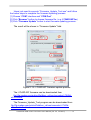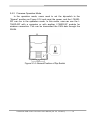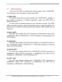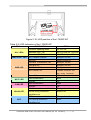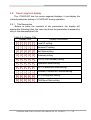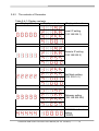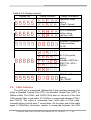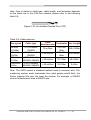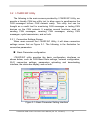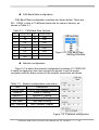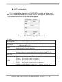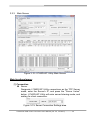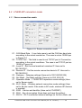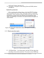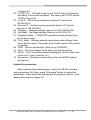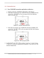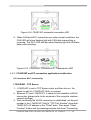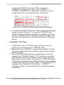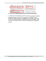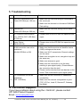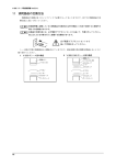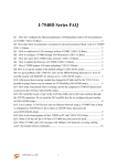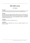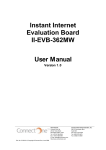
1
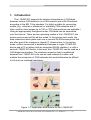
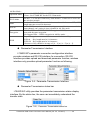
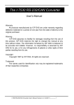
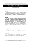
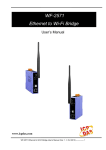
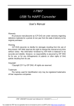
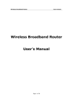
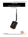
I-7540D-WF CAN to Wi-Fi Converter User’s Manual www.icpdas.com I-7540D-WF CAN to Wi-Fi Converter User’s Manual (Ver. 2.0, Jan/2012) ------------- 1 Warranty All products manufactured by ICP DAS are under warranty regarding defective materials for a period of one year from the date of delivery to the original purchaser. Warning ICP DAS assumes no liability for damages resulting from the use of this product. ICP DAS reserves the right to change this manual at any time without notice. The information furnished by ICP DAS is believed to be accurate and reliable. However, no responsibility is assumed by ICP DAS for its use, or for any infringements of patents or other rights of third parties resulting from its use. Copyright Copyright 2011 by ICP DAS. All rights are reserved. Trademark The names used for identification only may be registered trademarks of their respective companies. Document Revision Version 1.0 Author T.H. Date 2011-04-26 1.1 T.H. 2011-12-13 2.0 T.H. 2012-01-02 Description of changes First Release Revision Update images of module appearance Add CAN ID Filter function description I-7540D-WF CAN to Wi-Fi Converter User’s Manual (Ver. 2.0, Jan/2012) ------------- 2 Table of Contents 1. Introduction .......................................................................................5 1.1 1.2 Operation Mode ................................................................................. 6 Features............................................................................................. 6 1.3 Specifications ..................................................................................... 6 2. Hardware ...........................................................................................8 2.1 2.2 Block Diagram.................................................................................... 8 Pin Assignment .................................................................................. 9 2.3 Hardware Connection ........................................................................ 9 CAN port connection ........................................................................ 9 Serial port connection..................................................................... 10 Terminator Resistor Settings .............................................................11 2.3.1 2.3.2 2.4 2.5 2.6 2.6.1 Watchdog Timer Settings ................................................................. 12 Init / Normal Dip-switch .................................................................... 12 Firmware Update Mode.................................................................. 12 2.6.2 Firmware Operation Mode.............................................................. 15 LED Indication.................................................................................. 16 Seven-segment display.................................................................... 18 2.8.1 2.8.2 Title Description.............................................................................. 18 The contents of Parameter............................................................. 19 Cable Selection................................................................................ 20 2.7 2.8 2.9 3. Software...........................................................................................22 3.1 3.2 Connection and Configuration Tool – I-7540D-WF Utility ................. 22 I-7540D-WF Utility............................................................................ 23 Connection Settings Screen........................................................... 23 Basic Parameter configuration ......................................................... 23 CAN Baud Rate configuration .......................................................... 24 Network configuration ...................................................................... 24 Wi-Fi configuration ........................................................................... 25 Parameter Transmission Interface ................................................... 26 Parameter Transmission status bar.................................................. 26 Display Firmware Information .......................................................... 27 Parameter reading function.............................................................. 27 Parameter writing function ............................................................... 27 Exit parameter setting ...................................................................... 27 3.2.1 3.2.2 CAN ID Filter Settings Screen........................................................ 28 Single ID frame ................................................................................ 28 Group ID frame ................................................................................ 28 I-7540D-WF CAN to Wi-Fi Converter User’s Manual (Ver. 2.0, Jan/2012) ------------- 3 Get Accepted ID button .................................................................... 29 Set Accepted ID button .................................................................... 29 Add button........................................................................................ 29 Del button......................................................................................... 29 3.2.3 Main Screen ................................................................................... 30 4. Application Notes............................................................................36 4.1 4.2 Hardware Installation ....................................................................... 37 I-7540D-WF connection mode ......................................................... 38 4.2.1 4.2.2 4.3.1 Server connection mode ................................................................ 38 Client connection mode.................................................................. 39 Connection test ................................................................................ 41 Two I-7540D-WF connection application architecture .................... 41 4.3.2 I-7540D-WF and PC connection application architecture............... 42 4.3 5. Troubleshooting..............................................................................45 I-7540D-WF CAN to Wi-Fi Converter User’s Manual (Ver. 2.0, Jan/2012) ------------- 4 1. Introduction The I-7540D-WF supports the wireless transmission of CAN data between various CAN networks or a CAN network and a WLAN network according to the 802.11b/g standard. It is highly suitable for connecting mobile (e.g., vehicles or machines) or stationary CAN networks and is often used for short ranges up to 100 m.(TCP data protocols are available.) Using an appropriately configured router, CAN data can be transmitted over the Internet. There are two operating modes in the I-7540D-WF: the access point mode and the ad-hoc mode. In the access point mode, the data connection takes place over one or several WLAN access points that are often part of the company's internal IT infrastructure. In the ad-hoc mode, a direct connection is established between a single I-7540D-WF device and a PC or laptop (with an integrated WLAN interface), or with a second I-7540D-WF device. In this way, the I-7540D-WF can be used as a CAN diagnosis interface. The wireless connection that is established between two I-7540D-WF units can be used instead of a cable, and enables the connection of CAN networks that would otherwise be difficult to link such as rotational machinery. Figure 1-1: Application architecture for the I-7540D-WF I-7540D-WF CAN to Wi-Fi Converter User’s Manual (Ver. 2.0, Jan/2012) ------------- 5 1.1 Operation Mode I-7540D-WF provides wireless data transmission of CAN, and supports AP and Ad-hoc operation modes of WLAN. 1.2 • • • • • • • • • • • Features RoHS Design IEEE 802.11b/g compliant Built-in jumper to select 120 ohm terminal resister of CAN bus Watchdog inside Wireless data transmission via WLAN Support two operation modes: Infrastructure mode and Ad-hoc mode Support point to point or point to multi-points connection via WLAN Support WEP, WPA and WPA2 encryption for WLAN CAN 2.0A/2.0B compliant Support CAN bus acceptance filter configuration Communication efficiency(peak value): one-way is up to 700 fps (client>server, server->client),two-way 350 fps (client<=>server) • Wireless transmission distance: up to 100 meters 1.3 Specifications [ UART Specs: ] • Connector : 10-pin screw terminal connector(Pin1/ Pin2/ Pin3) • COM1 : RS-232(TXD, RXD, GND) • Baud Rate (bps) : 115200 [ CAN Specs: ] • Connector : 10-pin screw terminal connector(Pin5/ Pin6/ Pin7) • CAN Baud Rate : 5K ~ 1Mbps • Isolation Voltage : 3000 VDC power protection on CAN side, 2500Vrms photo-couple isolation on CAN bus • Terminator Resistor: Selectable 120Ω terminator resistor by jumper • Specification; ISO-11898-2, CAN 2.0A and CAN 2.0B [Wireless Specs: ] • Standard Supported : IEEE 802.11b & IEEE 802.11g • Frequency Range : 2.412GHz ~ 2.484GHz • Center Frequencies:Europe – 2.412GHz ~ 2.472GHz USA – 2.412GHz ~ 2.462GHz • Channels: Europe – 13 channels I-7540D-WF CAN to Wi-Fi Converter User’s Manual (Ver. 2.0, Jan/2012) ------------- 6 USA – 11 channels [Antenna Specs: ] • Connector : RP SMA Male (Plug) • Radiation : Omni-Directional • Band : 2.4 ~ 2.5GHz • Gain : 5 dBi [ Module Specs: ] • Dimensions : 117mm x 76mm x 37mm (H x W x D) • Operating temperature : -25 ~ 75ºC (-13 ~ 167ºF) • Storage temperature : -30 ~ 80ºC (-40 ~ 176ºF) • Humidity : 10 to 90%, non-condensing • LEDs : PWR LED - Power indicator Wi-Fi LED - Wi-Fi communication indicator CAN LED - CAN communication indicator WLAN LED - WLAN connection indicator CNT. LED - TCP connection indicator [ Utility Tool: ] • Provide WLAN connection and configuration interface • Provide WLAN encryption configuration interface • Provide CAN bus acceptance filter configuration interface • Provide CAN messages transmission / reception interface [ Application: ] • Factory Automation • Building Automation • Home Automation • Control System • Monitor System • Vehicle Automation I-7540D-WF CAN to Wi-Fi Converter User’s Manual (Ver. 2.0, Jan/2012) ------------- 7 2. Hardware Figure 2-1: Hardware externals of the I-7540D-WF 2.1 Block Diagram Figure 2-2 is a block diagram illustrating the functions on the I-7540DWF module. It provides the 3000Vrms Isolation in the CAN interface site. Figure 2-2: Block diagram of the I-7540D-WF I-7540D-WF CAN to Wi-Fi Converter User’s Manual (Ver. 2.0, Jan/2012) ------------- 8 2.2 Pin Assignment Table 2-1: 10-pin screw terminal connecter 10-pin screw terminal connecter Pin Description 1 RS-232 RXD 2 RS-232 TXD 3 RS-232 GND 4 Not Connect 5 CAN_H 6 CAN_L 7 CAN_GND 8 Not Connect 9 +Vs(+10 ~ +30 VDC) 10 GND Figure 2-3: Pin Assignment on the I-7540D-WF 2.3 Hardware Connection I-7540D-WF module supports the CAN data wireless communications, it provides a wireless link interface for CAN network, and the RS-232 interface provides to configuration the parameter of product. 2.3.1 CAN port connection The hardware connection between device and the I-7540D-WF is as Figure 2-4. I-7540D-WF CAN to Wi-Fi Converter User’s Manual (Ver. 2.0, Jan/2012) ------------- 9 Figure 2-4: CAN Hardware Wire Connection 2.3.2 Serial port connection The I-7540D-WF offers RS-232 serial interfaces to the user. The following figures describe the COM port to a serial device via serial network. Figure 2-5: RS-232 Wire Connection I-7540D-WF CAN to Wi-Fi Converter User’s Manual (Ver. 2.0, Jan/2012) ------------- 10 2.4 Terminator Resistor Settings According to the ISO 11898 specifications, the CAN Bus network must be terminated by two terminal resistors (120Ω) for proper operation, as shown in the following figure. Figure 2-6: Terminal Resistor Therefore, the I-7540D-WF module supplies a jumper for users to active the terminal resistor or not. If users want to use this terminal resistor, please open the I-7540D-WF cover and use the JP2 to activate the 120Ω terminal resistor built in the module, as the Figure 2-7. Note that the default setting is active. The purpose of the terminal resistor is used to terminate the electrical signal, in order to avoid reflected signals interfere with the normal signal transduction. If the I-7540D-WF is not in the terminal at the CAN network, the termination resistors should not be enabled. Figure 2-7: Terminal Resistor Jumper I-7540D-WF CAN to Wi-Fi Converter User’s Manual (Ver. 2.0, Jan/2012) ------------- 11 Enable (default) Disable Figure 2-8: Terminal resistor JP2 Jumper Position 2.5 Watchdog Timer Settings A watchdog timer (WDT) is a device that performs a specific operation after a certain period of time if something goes wrong and the system does not recover on its own. A watchdog timer can perform a warm boot(restarting the system) after a certain number of milliseconds. The I-7540D-WF module supplies a jumper for users to active the watchdog timer or not. If users want to use this WDT, can open the I7540D-WF cover and use the JP1 to activate the WDT built in the module, as the Figure 2-7. Note that the default setting is active. Enable (default) Disable Figure 2-9: Watchdog timer JP1 Jumper Position 2.6 Init / Normal Dip-switch On the back of the I-7540D-WF module, there is a dip-switch used for firmware operation or firmware updating of the module. The following steps show how to use this dip-switch. 2.6.1 Firmware Update Mode Please set the dip-switch to the “Init” (Initial) position as Figure 2-10, and then the I-7540D-WF will work in the “Firmware Update Mode” after reset the power of the module. In this mode, users can update the I-7540D-WF CAN to Wi-Fi Converter User’s Manual (Ver. 2.0, Jan/2012) ------------- 12 firmware of the I-7540D-WF module from computer’s RS-232 port via CA0910 cable shown as Figure 2-12. Figure 2-10: Init Position of Dip-Switch Figure 2-11: CA-0910 Cable Figure 2-12: Firmware downloads connection I-7540D-WF CAN to Wi-Fi Converter User’s Manual (Ver. 2.0, Jan/2012) ------------- 13 Users just need to execute “Firmware_Update_Tool.exe” and follow the below steps to complete the firmware updating process. [1] Choose “COM” interface and “COM Port”. [2] Click “Browser” button to choose firmware file. (e.g. I-7540D-WF.fw) [3] Click “Firmware Update” button to start firmware updating process. The result will be shown in “Firmware Update” field. 1 2 3 6 4 5 Figure 2-13: I-7540D-WF firmware update process The I-7540D-WF firmware can be downloaded from ftp://ftp.icpdas.com/pub/cd/fieldbus_cd/can/converter/i-7540dwf/firmware/ The Firmware_Update_Tool program can be downloaded from ftp://ftp.icpdas.com/pub/cd/fieldbus_cd/can/converter/i-7540dwf/software/tool/ I-7540D-WF CAN to Wi-Fi Converter User’s Manual (Ver. 2.0, Jan/2012) ------------- 14 2.6.2 Firmware Operation Mode In the operation mode, users need to set the dip-switch to the “Normal” position as Figure 2-14 and reset the power, and the I-7540DWF can run in the operation mode. In this mode, user can use the I7540D-WF with a computer or with another I-7540D-WF module for wireless connection. This can be transmitted the CAN data through the WLAN. Figure 2-14: Normal Position of Dip-Switch I-7540D-WF CAN to Wi-Fi Converter User’s Manual (Ver. 2.0, Jan/2012) ------------- 15 2.7 LED Indication There are five LEDs to indicate the various states of the I-7540D-WF. The following is the illustration of these five LEDs. (1) PWR LED : It is used to help users to check whether the I-7540D-WF is standby. If the module is working in “firmware operation” mode, the PWR LED is always turned on. It is also used for demonstrating an error that has occurred. The PWR LED is normally turned on when the module works in a good condition. For different error conditions represented by the indicator LED, please refer to Table 2-2. (2) Wi-Fi LED : This LED can indicate the Wi-Fi reception or transmission state of the I-7540D-WF. When I-7540D-WF is in Wi-Fi sending or receiving state, the LED will blink. (3) CAN LED : This LED can indicate the CAN data reception or transmission state of the I-7540D-WF. When I-7540D-WF is in CAN data sending or receiving state, the LED will blink. (4) WLAN LED : This LED can indicate whether the I-7540D-WF’s WLAN connection is established. When WLAN connection is established, the LED will be normally on; otherwise, it will be flashing or off. (5) CNT. LED : This LED can indicate whether the I-7540D-WF’s TCP connection is established. When TCP connection is established, the LED will be normally on; otherwise, it will be flashing. I-7540D-WF CAN to Wi-Fi Converter User’s Manual (Ver. 2.0, Jan/2012) ------------- 16 Figure 2-15: LED position of the I-7540D-WF Table 2-2: LED indication of the I-7540D-WF LED Name ALL LEDs PWR & CNT. LED PWR LED Wi-Fi LED CAN LED WLAN LED CNT. I-7540D-WF Status LED Status Firmware Updating Mode All LED On Hardware WDT Fail All LED blink per 1 second Contact to ICP DAS Wi-Fi Module Failure All LED blink per 100 ms No Error Always turned on CAN Bus Transmission Fail Blink per 100 ms CAN Bus-Off Blink per 500 ms CAN Buffer Full Blink per 1 sec Wi-Fi Buffer Full Flashes twice per 100 ms , every 1 second Power Failure Off Data transmission Blink Bus Idle Off Data transmission Blink Bus Idle Off WLAN connection established Always turned on WLAN during connection establishment Blink or Off TCP connection established Always turned on TCP during connection establishment Blink Blink per 500 ms I-7540D-WF CAN to Wi-Fi Converter User’s Manual (Ver. 2.0, Jan/2012) ------------- 17 2.8 Seven-segment display The I-7540D-WF has five seven-segment displays; it can display the internal parameter setting of I-7540D-WF during operation. 2.8.1 Title Description Before to show the contents of the parameters, the display will appear the following titles, the user may know the parameter at present by way of this demonstration title. Table 2-3: Display Title Display Title Display Information Local IP setting Remote IP setting Net Mask setting Gateway setting TCP/IP Port Number setting Operation Mode setting Wi-Fi Connection Mode setting Wireless Connection Channel setting Wi-Fi Encryption setting CAN Baud Rate setting I-7540D-WF CAN to Wi-Fi Converter User’s Manual (Ver. 2.0, Jan/2012) ------------- 18 2.8.2 The contents of Parameter Table 2-4-1: Display contents Display title Display contents Display information Local IP setting (192.168.255.1) Remote IP setting (192.168.255.2) Net Mask setting (255. 255.0. 0) Gateway setting (192.168.255.254) TCP/IP Port Number setting (10000) I-7540D-WF CAN to Wi-Fi Converter User’s Manual (Ver. 2.0, Jan/2012) ------------- 19 Table 2-4-2: Display contents Display title Display contents Display information Operation Mode setting (Client / Server) Wi-Fi Connection Mode setting (Ad-Hoc / AP) Wireless Connection Channel setting (0~13) Wi-Fi Encryption setting (Disable / WEP-64 / WEP-128 / WPA / WPA2) CAN Baud Rate setting (5K~1000K) 2.9 Cable Selection The CAN bus is a balanced (differential) 2-wire interface running over either a Shielded Twisted Pair (STP), Un-shielded Twisted Pair (UTP), or Ribbon cable. The CAN-L and CAN-H Wire start on one end of the total CAN network that a terminator of 120 Ohm is connected between CAN-L and CAN-H. The cable is connected from CAN node to CAN node, normally without or with short T connections. On the other end of the cable again a 120Ω(Ohm) terminator resistor is connected between the CAN I-7540D-WF CAN to Wi-Fi Converter User’s Manual (Ver. 2.0, Jan/2012) ------------- 20 lines. How to decide a cable type, cable length, and terminator depends on the baud rate in the CAN bus network, please refer to the following table 2-5. Figure 2-18: Un-shielded Twisted Pair (UTP) Table 2-5: Cable selection Bus speed 50k bit/s at 1000m 100k bit/s at 500m 500k bit/s at 100m 1000k bit/s at 40m Cable type 0.75~0.8mm2 18AWG 0.5~0.6 mm2 20AWG 0.34~0.6mm2 22AWG, 20AWG 0.25~0.34mm2 23AWG, 22AWG Cable Terminator Bus Length Resistance/m 150~300 70 mOhm 600~1000m Ohm 150~300 < 60 mOhm 300~600m Ohm < 40 mOhm 127 Ohm 40~300m < 40 mOhm 124 Ohm 0~40m Note: The AWG means a standard method used to measure wire. The numbering system works backwards from what people would think, the thicker (heavier) the wire, the lower the number. For example: a 24AWG wire is thicker/heavier than a 26AWG wire. I-7540D-WF CAN to Wi-Fi Converter User’s Manual (Ver. 2.0, Jan/2012) ------------- 21 3. Software This chapter explains how to uses the I-7540D-WF Utility to carry on the I-7540D-WF wireless communication configuration 、 Established TCP connection and Transmission / Reception CAN messages. 3.1 Connection and Configuration Tool – I-7540D-WF Utility I-7540D-WF wireless connection and configuration tools can be used to set the I-7540D-WF wireless network interface, and for TCP connection and CAN message reception and transmission. I-7540D-WF Utility is a Microsoft Windows application that communicates with a I-7540D-WF over a standard RS-232 serial link by using the PC serial port. It is compatible with Microsoft Windows 95, 98, NT, 2000, Vista and 7. The I-7540D-WF Utility can be downloaded from ftp://ftp.icpdas.com/pub/cd/fieldbus_cd/can/converter/i-7540dwf/software/utility/ I-7540D-WF CAN to Wi-Fi Converter User’s Manual (Ver. 2.0, Jan/2012) ------------- 22 3.2 I-7540D-WF Utility The following is the main screens provided by I-7540D-WF Utility, we provide a friendly CAN bus utility tool to allow users to send/receive the CAN messages to/from CAN network easily. This utility tool can be thought as a useful tool for monitoring CAN messages or testing CAN devices on the CAN network. It supplies several functions, such as sending CAN messages, receiving CAN messages, storing CAN messages, cyclic transmission, and so forth. 3.2.1 Connection Settings Screen When users execute the I-7540D-WF Utility, it will show connection settings screen first as Figure 3-1. The following is the illustration for connection parameters. Basic Parameter configuration I-7540D-WF utility provides the basic configuration interfaces as shown below, such as CAN Baud Rate settings, network configuration, Wi-Fi connection settings, parameters uploading and downloading interface, the status bar display, and so forth. Figure 3-1: Basic Parameter Setting Interface I-7540D-WF CAN to Wi-Fi Converter User’s Manual (Ver. 2.0, Jan/2012) ------------- 23 CAN Baud Rate configuration CAN Baud Rate configuration interface are shown below. There are 5K ~ 1000K, a total of 15 different baud rate for users to choose, as shown in Table 3-1. Table 3-1: CAN Baud Rate Options Item CAN Baud Rate Item CAN Baud Rate 1 5K 9 200K 2 10K 10 250K 3 20K 11 400K 4 40K 12 500K 5 50K 13 600K 6 80K 14 800K 7 100K 15 1000K 8 125K Figure 3-2: CAN Baud Rate Setting Interface Network configuration Figure 3-3 is about the network configuration interface of I-7540D-WF. It needs to depend on the user connection request to set the scene consistent with the basic content of the network connection as follows. Table 3-2: Network configuration instructions Item Description TCP/IP Port TCP/IP Port Number Setting Local IP Local IP Setting Remote IP Remote IP Setting Gateway Gateway Setting Net Mask Net Mask Setting MAC Address MAC Address Display Figure 3-3: :Network configuration I-7540D-WF CAN to Wi-Fi Converter User’s Manual (Ver. 2.0, Jan/2012) ------------- 24 Wi-Fi configuration Wi-Fi configuration interface of I-7540D-WF is shown as below, such as Wi-Fi connection mode, SSID, WLK, WLCH, Encryption, and so forth. The detailed description is as the following table. Figure 3-4: Wi-Fi Configuration Interface AP Mode: Operation Mode Wi-Fi Mode SSID WLCH Encryption WLK Server:Set I-7540D-WF for the TCP Server mode. Client:Set I-7540D-WF for the TCP Client mode. AP:Use the wireless access point way for connection and transmission. (Must have Wi-Fi AP) Service Set Identifier: Connected devices must be with the same SSID, SSID length must not exceed 20 characters. 0~13:Wi-Fi transmission channel setting, connected devices must with the same channel. Setting 0 (Auto) for automatically channel modulation with Wi-Fi AP. NONE / WEP64 / WEP128 / WPA / WPA2: Encryption of Wi-Fi, connected devices must with the same encryption. Key of Encryption,connected devices must with the same Key. WEP-64 :Key length must be 10 characters. WEP-128:Key length must be 26 characters. WPA :Key length must between 8~64 characters. WPA2 :Key length must between 8~64 characters. Characters of key should be in range of: [0 ~ 9] or [A ~ F] or [a ~ f]. I-7540D-WF CAN to Wi-Fi Converter User’s Manual (Ver. 2.0, Jan/2012) ------------- 25 Ad-Hoc Mode: Operation Mode Wi-Fi Mode SSID WLCH Encryption WLK Server:Set I-7540D-WF for the TCP Server mode. Client:Set I-7540D-WF for the TCP Client mode. Ad-Hoc:Use Ad-Hoc connectivity with another I-7540D-WF to create ADhoc wireless network. Service Set Identifier: Connected devices must be with the same SSID, SSID length must not exceed 20 characters. 1~13:Wi-Fi transmission channel setting, connected devices must with the same channel, can’t setting 0 (Auto) channel in Ad -Hoc mode. NONE / WEP64 / WEP128: Wi-Fi Encryption of Wi-Fi, connected devices must with the same encryption. Not Support WPA、WPA2 encryption in Ad-Hoc mode。 Key of Encryption,connected devices must with the same Key. WEP-64 :Key length must be 10 characters. WEP-128:Key length must be 26 characters. Characters of key should be in range of: [0 ~ 9] or [A ~ F] or [a ~ f]. Parameter Transmission Interface I-7540D-WF's parameter connection configuration interface provides wireless and RS-232 interface for connection, RS-232 interface provides upload and download parameter function; wireless interface only provides upload parameter function as following. Figure 3-5: Parameter Transmission Interface Parameter Transmission status bar I-7540D-WF utility provides the parameter transmission status display interface. By the status bar, the user can immediately understand the transfer state. Figure 3-6: Parameter Transmission status bar I-7540D-WF CAN to Wi-Fi Converter User’s Manual (Ver. 2.0, Jan/2012) ------------- 26 Display Firmware Information The following figures display the firmware’s version and date created inside the I-7540D-WF. Figure 3-7 Firmware version and Date created Parameter reading function I-7540D-WF utility provides parameters download function for I7540D-WF by the RS-232 interface. It allows user to download the parameters form I-7540D-WF. Figure 3-8: Parameter reading button Parameter writing function I-7540D-WF utility provides parameters upload function for I7540D-WF by the RS-232 and Wi-Fi interfaces to allow users to upload the parameters to I-7540D-WF. Figure 3-9: Parameter writing button Exit parameter setting Press this button to exit I-7540D-WF Utility of the parameter setting interface and return to the main screen. Figure 3-10: Exit parameter setting button I-7540D-WF CAN to Wi-Fi Converter User’s Manual (Ver. 2.0, Jan/2012) ------------- 27 3.2.2 CAN ID Filter Settings Screen If the filter without setting any rules, the default is allowed to receive all CAN messages. In CAN ID Filter setting screen, users can set which CAN ID able to be received by I-7540D-WF module. Figure 3-11: CAN ID Filter Settings Screen Single ID frame By clicking “Add” button to add the assigned single CAN ID to “ID Filter” table to set these assigned single CAN ID able to be received. Group ID frame By clicking “Add” button to add the assigned group CAN ID to “ID Filter” table to set these assigned group CAN ID able to be received. I-7540D-WF CAN to Wi-Fi Converter User’s Manual (Ver. 2.0, Jan/2012) ------------- 28 Add button It is used to add the CAN Filter-ID data to the “ID Filter” table. Del button It is used to delete the CAN Filter-ID data of the assigned row in “ID Filter” table. Get Accepted ID button It is used to get CAN Filter-ID data from I-7540D-WF and showed in the “ID Filter” table. Set Accepted ID button It is used to set CAN Filter-ID data to I-7540D-WF according to the “ID Filter” table content. I-7540D-WF CAN to Wi-Fi Converter User’s Manual (Ver. 2.0, Jan/2012) ------------- 29 3.2.3 Main Screen Figure 3-12: I-7540D-WF Utility Main Screen Main functional areas: [1] Connection Server Designate I-7540D-WF Utility connections as the TCP Server mode, enter the Server's IP, and press the "Server Listen" button. I-7540D-WF Utility will enter server listening mode, and waiting for client connection. Figure 3-13: Server Connection Settings area I-7540D-WF CAN to Wi-Fi Converter User’s Manual (Ver. 2.0, Jan/2012) ------------- 30 Client Designate I-7540D-WF Utility connections for the TCP Client mode, enter the Server's IP, and press the "Client Listen" button. I-7540D-WF Utility will connect with the Server. Figure 3-14: Client Connection Settings area TCP Port Number Set I-7540D-WF Utility TCP connection Port Number, and this setting must the same with the I-7540D-WF's Port Number for normal connections. Figure 3-15: TCP Port Number Settings area Send To Specify the IP location for CAN data to be sent via the WLAN. This setting can only be specified in the connection status. Figure 3-16: IP designated area for CAN data transmission System Message This area will display information for the system connection, such as waiting for the connection, the connection is successful, read data, and etc. Figure 3-17: System message display area I-7540D-WF CAN to Wi-Fi Converter User’s Manual (Ver. 2.0, Jan/2012) ------------- 31 Clear Message Press this button to clear the contents of system message display area. Figure 3-18: Clear button for message display area Close Socket Press this button to close the currently open Socket. Figure 3-19: Close TCP connection button [2] CAN Transmission / Reception CAN Transmission In the CAN port transmitting page as the following figure, there are five functions to use, such as Add, Modify, Delete, Send and Clear Count. Figure 3-20: CAN data transfer settings and operating area Add: User can key in the CAN message into the text boxes above the transmission list. Click “Add” button to insert this CAN message into transmission list. The transmission list can include maximum 20 CAN messages. After adding the message into transmission list, I-7540D-WF CAN to Wi-Fi Converter User’s Manual (Ver. 2.0, Jan/2012) ------------- 32 users can send this message to CAN network via WLAN by using “Send” button. Modify: If users want to modify the content of some CAN message in the transmission list, they can select this CAN messages in the transmission list firstly. Then, this CAN message information will be shown in the text boxes above the transmission list. Users can modify the CAN message in these text boxes directly. Finally, click “Modify” button to save the modification in the list. Delete: If some CAN message in the transmission list is useless, users can select it and click “Delete” button to delete this CAN message from transmission list. Send: After users select one CAN message from transmission list, click “Send” button to send this CAN message once from the selected CAN port. If the timer parameter of this CAN message is not 0, the CAN message will be sent depending on this timer parameter periodically. In this case, the status filed of this CAN message in transmission list will display “Running”, and the text shown on the Send button will be changed to “Pause”. If uses want to stop the message transmission, click this button again. There are only 5 CAN messages can be sending cyclically at the same time. Clear Count: Right of the display area will record the counter of CAN transfer packets. If users want to clear this transfer count, click on "Clear Count" button. I-7540D-WF CAN to Wi-Fi Converter User’s Manual (Ver. 2.0, Jan/2012) ------------- 33 CAN Reception The following figure shows the receive part of a selected CAN port. There are two function buttons for reception list, such as Rx Pause and Clear。 Figure 3-21: CAN data receive settings and operating area Rx Pause: Click this button to stop the CAN message reception from WLAN. Click it again to continue the message reception. Clear: Click this button to delete all CAN messages shown in the reception list. Menu Function: [1] File Load Configuration If users have saved the configuration by using I-7540D-WF Utility before, users can click Load Configuration function to load the older records into these lists of I-7540D-WF Utility. Save Configuration The function is used for saving the transmission list to a txt file. Save Reception List Save Receive List, is used for saving the CAN messages that is received on the reception list. The data in the reception list will be saved into txt file. I-7540D-WF CAN to Wi-Fi Converter User’s Manual (Ver. 2.0, Jan/2012) ------------- 34 [2] Configuration Module Configuration This function can enter the basic configuration interface, as shown in Figure 3-1. CAN ID Filter This function can enter the CAN ID Filter setting interface, as shown in Figure 3-11 [3] About: The function can show the version information of I-7540D-WF Utility as shown below. Figure 3-22: I-7540D-WF Utility Version Information I-7540D-WF CAN to Wi-Fi Converter User’s Manual (Ver. 2.0, Jan/2012) ------------- 35 4. Application Notes In practice, users can use the two I-7540D-WF or a set of I-7540D-WF with the computer (with supporting for wireless network) connection structure in the application. It can complete the purpose of transferring CAN data to wireless network by this way. I-7540D-WF wireless connection can replace the cable, for some hard wiring or the CAN data transmission distance requirements, that is a very good option. Figure 4-1: I-7540D-WF application architecture (two I-7540D-WF) Figure 4-2: I-7540D-WF application architecture (I-7540D-WF + PC) I-7540D-WF CAN to Wi-Fi Converter User’s Manual (Ver. 2.0, Jan/2012) ------------- 36 4.1 Hardware Installation Before use, associated hardware configuration, the steps described as follows: Step 1: Checking the I-7540D-WF firmware operation mode In the operation mode, the user can complete the wireless CAN data transmission via the I-7540D-WF. It needs to set the DIP switch to the Normal position (operating mode) as Figure 2-14; as resetting the power, I-7540D-WF will be in the operation mode. Step 2: Enabling 120Ω termination resistors (if I-7540D-WF is a terminal in the CAN network) Please open the I-7540D-WF cover and use the JP2 to activate the 120Ω terminal resistor built in the module, as the Figure 2-7, After finishing set the JP2, 120 ohm termination resistors can be enabled. Step 3: CAN bus network connection Refer to Figure 2-4 for wiring structure, and connect the I-7540D-WF's CAN interface with other devices. Step 4: Serial port connection I-7540D-WF supports RS-232 serial communication. The circuit configuration is as shown in Figure 2-5. Step 5: Power connection Connect the power supply to I-7540D-WF's power terminator, as shown in Figure 4-3. Figure 4-3: Power Wiring I-7540D-WF CAN to Wi-Fi Converter User’s Manual (Ver. 2.0, Jan/2012) ------------- 37 4.2 I-7540D-WF connection mode 4.2.1 Server connection mode Figure 4-4: Server connection mode 01、CAN Baud Rate : It can help users to set the CAN bus baud rate according to the actual connection. The case is set as 1000K bps in Figure 4-4 02、TCP/IP Port : This field is used to set TCP/IP port of Connection according to the actual conditions. The case is set TCP/IP port as 10000 in Figure 4-4 03、Local IP : Set the local machine's wireless IP. Here set to 192.168.255.1 04、Remote IP : Set the remote connection device's IP. Here set to 192.168.255.2 05、Gateway : Gateway settings (Here set to 192.168.255.254) 06、Net Mask : Net Mask settings (Here set to 255. 255.0.0) 07、Operation Mode : I-7540D-WF's operation mode settings (Here set to Server mode) 08、Wi-Fi Mode : Wireless network connection mode settings (Here set to Ad-Hoc mode. If the mode is AP mode, wireless AP devices is needed) 09、SSID : Service set identifier (Here set to I7540DWF) 10、WLK : Key of encryption (Here does not have the setting) 11、WLCH : Wi-Fi connection channel settings (In Ad Hoc mode, can I-7540D-WF CAN to Wi-Fi Converter User’s Manual (Ver. 2.0, Jan/2012) ------------- 38 not be set 0 (Auto), here set to 1) 12、Encryption : Encryption mode setting (Here set NONE (without encryption)) Upload the parameters After completing the settings above, select the RS-232 interface and connections Port Num. Press "Write para" Button to upload the parameters, If the connection settings and the wiring are correct, the transmission process status bar will show the transmission state below. As uploading is successful, the upload window will appear as shown below. Figure 4-5: Parameter transmission status and upload successfully screens 4.2.2 Client connection mode Figure 4-6: Client connection mode 01、CAN Baud Rate : It can help users to set the CAN bus baud rate according to the actual connection. The case is set as 1000K bps I-7540D-WF CAN to Wi-Fi Converter User’s Manual (Ver. 2.0, Jan/2012) ------------- 39 in Figure 4-6 02、TCP/IP Port : This field is used to set TCP/IP port of Connection according to the actual conditions. The case is set TCP/IP port as 10000 in Figure 4-6 03、Local IP : Set the local machine's wireless IP. Here set to 192.168.255.2 04、Remote IP : Set the remote connection device's IP (Server). Here set to 192.168.255.1 05、Gateway : Gateway settings (Here set to 192.168.255.254) 06、Net Mask : Net Mask settings (Here set to 255. 255.0.0) 07、Operation Mode : I-7540D-WF's operation mode settings (Here set to Client mode) 08、Wi-Fi Mode : Wireless network connection mode settings (Here set to Ad-Hoc mode. If the mode is AP mode, wireless AP devices is needed) 09、SSID : Service set identifier (Here set to I7540DWF) 10、WLK : Key of encryption (Here does not have the setting) 11、WLCH : Wi-Fi connection channel settings (In Ad Hoc mode, can not be set 0 (Auto), here set to 1) 12、Encryption : Encryption mode setting (Here set NONE (without encryption)) Upload the parameters After completing the settings above, select the RS-232 interface and connections Port Num, press "Write para" button to upload the parameters. If the connection settings and the wiring are correct, it will appear the screen as Figure 4-5. I-7540D-WF CAN to Wi-Fi Converter User’s Manual (Ver. 2.0, Jan/2012) ------------- 40 4.3 Connection test 4.3.1 Two I-7540D-WF connection application architecture 1、Power on the two I-7540D-WF (TCP Client / TCP Server). 2、After about 10 seconds, two I-7540D-WF will first establish Ad-Hoc connection. WLAN LED on the front panel will be form flashing state to normally ON. Figure 4-7: Ad-Hoc connection LED 3、After about 5 seconds, two I-7540D-WF will further establish TCP connection. The CNT. LED on the front panel will also form flashing state to normally ON. Figure 4-8: TCP connection LED 4、As WLAN LED and CAN. LED are always turned on, it means the two I-7540D-WF connection established successfully. This can be for CAN wireless transmission. I-7540D-WF CAN to Wi-Fi Converter User’s Manual (Ver. 2.0, Jan/2012) ------------- 41 Figure 4-9: I-7540D-WF successful connection LED 5、When CAN and Wi-Fi connection are under normal conditions, the CAN LED will show flashing light with CAN data transmitting or receiving; The Wi-Fi LED will also show flashing light with Wireless data communicating. Figure 4-10: I-7540D-WF CAN and Wi-Fi Transmission LED 4.3.2 I-7540D-WF and PC connection application architecture (PC must have Wi-Fi connectivity) I-7540D-WF - TCP Server 1、I-7540D-WF is set to TCP Server mode, and then turn on the power to wait for I-7540D-WF Utility to connect. 2、Between PC and I-7540D-WF, it needs to first establish a WLAN connection (please refer to the contents of the computer wireless network settings). 3、After confirming the WLAN connection is established, set the port number in the I-7540D-WF Utility's "TCP Port Number" area and I7540D-WF's IP address in the "Client" area. Then press "Client: Connect" button and the message window will show "Connecting I-7540D-WF CAN to Wi-Fi Converter User’s Manual (Ver. 2.0, Jan/2012) ------------- 42 to Server (192.168.255.1) on Port 10000.... (waiting for CONNECT)" message. If the "Server (192.168.255.1) -> CONNECT SUCCESSFUL, 0 Bytes sent" messages is shown, it means that the TCP connection has been successfully. 1 3 2 4 Figure 4-11: I-7540D-WFUtility-Client connection procedure 4、If I-7540D-WF WLAN LED and CNT. LED on the panel are always turned on, refer to Figure 4-9, it means the I-7540D-WF and I7540D-WF Utility connection established successfully. Users can use the I-7540D-WF Utility to transmit or receive CAN data. User can refer to the description in the CAN Transmission / Reception section. I-7540D-WF - TCP Client 1、I-7540D-WF is set to TCP Client mode, and then turn on the power to wait to connect to the I-7540D-WF Utility. 2、Between PC and I-7540D-WF, it needs to first establish a WLAN connection (please refer to the contents of the computer wireless network settings). 3、After confirm the WLAN connection is established, set the port number in the I-7540D-WF Utility's "TCP Port Number" area and select the Server IP (PC's IP location) In the "Server" area, then press "Server: Listen" button. In this time the I-7540D-WF Utility is in waiting for connection status and the message window will show "Listening (192.168.255.1) on Port 10000.... (waiting for ACCEPT)" message. If the "Client 238 (192.168.255.2) --> ACCEPT" messages is shown, it means that the TCP connection has been successfully. I-7540D-WF CAN to Wi-Fi Converter User’s Manual (Ver. 2.0, Jan/2012) ------------- 43 3 2 1 4 Figure 4-12: I-7540D-WFUtility-Server connection procedure 4、If I-7540D-WF WLAN LED and CNT. LED on the panel are always turned on, refer to Figure 4-9, it means the I-7540D-WF and I7540D-WF Utility connection established successfully. Users can use the I-7540D-WF Utility to transmit or receive CAN data. User can refer to the description in the CAN Transmission / Reception section. I-7540D-WF CAN to Wi-Fi Converter User’s Manual (Ver. 2.0, Jan/2012) ------------- 44 5. Troubleshooting Item Problem Description 1 2 3 Solution CAN Bus Transmission Fail (Power LED Blink per 100 ms) 1. Make sure the CAN bus wiring is connected to the correct pin. 2. Make sure the devices is in the same CAN Baud Rate setting. CAN Bus-Off (Power LED Blink per 500 ms) 1. Make sure the CAN bus wiring is not in shortcircuit Wi-Fi module communication error (PWR & CNT. LED Blink 1. Please return to the ICP DAS for inspection and repair per 500 ms) 4 Power Failure (PWR LED Off) WLAN connection can not be established (WLAN LED Blink or Off) 1. Please return to the ICP DAS for inspection and repair 1. Make sure that the service set identifier device (SSID) settings are the same. 2. Make sure Wi-Fi transmission Channel settings are the same. 3. Make sure encryption is set, encryption keys are the same way 4. Make sure antenna is good 5. Make sure the connection is too far away, resulting in poor signal quality. (Please shorten the connection from the test) 5 6. Please confirm whether there are barriers on the scene. That could result in poor signal quality. 6 TCP connection can not be 1. Make sure WLAN connection is established established (CNT. LED Blink) successfully 2. Make sure the network configuration is good (TCP / IP Port, Local IP, Remote IP, Gateway, Net Mask) Technical Support If you have problems about using the I-7540D-WF, please contact ICP DAS Product Support. Email: [email protected] I-7540D-WF CAN to Wi-Fi Converter User’s Manual (Ver. 2.0, Jan/2012) ------------- 45