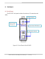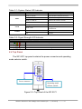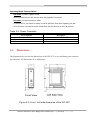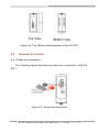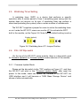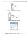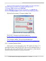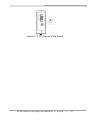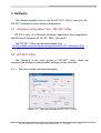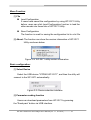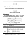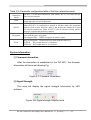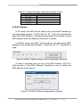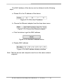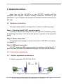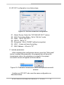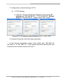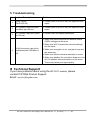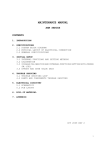
1
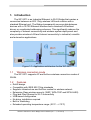
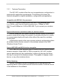
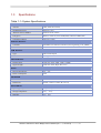
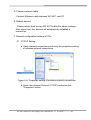
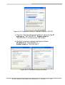
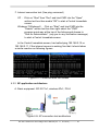
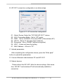
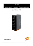
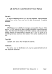
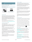
WF-2571
Ethernet to Wi-Fi Bridge
User’s Manual
www.icpdas.com
WF-2571 Ethernet to Wi-Fi Bridge User’s Manual (Ver. 1.1, Oct 2013) ------------- 1
Warranty
All products manufactured by ICP DAS are under warranty regarding
defective materials for a period of one year from the date of delivery to the
original purchaser.
Warning
ICP DAS assumes no liability for damages resulting from the use of
this product. ICP DAS reserves the right to change this manual at any time
without notice. The information furnished by ICP DAS is believed to be
accurate and reliable. However, no responsibility is assumed by ICP DAS
for its use, or for any infringements of patents or other rights of third
parties resulting from its use.
Copyright
Copyright 2013 by ICP DAS. All rights are reserved.
Trademark
The names used for identification only may be registered trademarks
of their respective companies.
Document Revision
Version
1.0
Author
T.H.
Date
2013-02-20
1.1
T.H.
2013-10-24
Description of changes
First release revision
Modify explanation of Wi-Fi
encryption configuration
WF-2571 Ethernet to Wi-Fi Bridge User’s Manual (Ver. 1.1, Oct 2013) ------------- 2
Table of Contents
1. Introduction .......................................................................................4
1.1
1.2
Wireless connection mode ................................................................. 4
Features............................................................................................. 4
1.2.1
1.3
Features Description ........................................................................ 5
Specifications ..................................................................................... 6
2. Hardware ...........................................................................................7
2.1
Front Panel ........................................................................................ 7
2.2
2.3
2.4
2.4.1
Top Panel ........................................................................................... 8
Dimensions ........................................................................................ 9
Hardware Connection ...................................................................... 10
Power wire connection ................................................................... 10
2.6.1
Watchdog Timer Setting....................................................................11
FW / OP Dip-switch...........................................................................11
Firmware Update Mode...................................................................11
2.6.2
Firmware Operation Mode.............................................................. 13
2.5
2.6
3. Software...........................................................................................15
3.1
Wireless Configuration Tool – WF-2571 Utility ................................. 15
3.2
WF-2571 Utility ................................................................................ 15
The main screen interface description ........................................... 15
3.2.1
4. Application Notes............................................................................21
4.1
Hardware Installation ....................................................................... 21
4.2
Connection Application..................................................................... 21
Ad-Hoc application architecture ..................................................... 21
AP application architecture............................................................. 25
4.2.1
4.2.2
5. Troubleshooting..............................................................................28
WF-2571 Ethernet to Wi-Fi Bridge User’s Manual (Ver. 1.1, Oct 2013) ------------- 3
1. Introduction
The WF-2571 is an Industrial Ethernet to Wi-Fi Bridge that creates a
connection between an 802.11b/g wireless LAN and a device with a
standard Ethernet port. The Bridge transparently conveys data between
devices with a 10/100 Ethernet interface and a wireless LAN without
drivers or complicated addressing schemes. This significantly reduces the
complexity of network connectivity and wireless system deployment and
also provides wireless LAN and Internet connectivity to industrial, scientific
and automotive applications.
Figure 1-1: Application architecture for the WF-2571
1.1
Wireless connection mode
The WF-2571 supports AP and Ad-hoc wireless connection modes of
WLAN.
1.2
•
•
•
•
•
•
•
•
•
Features
RoHS design
Compatible with IEEE 802.11b/g standards
Supports Infrastructure and Ad-Hoc modes for wireless network
Enterprise Class wireless security (WEP, WPA-TKIP and WPA2-AES)
Plug-and-Play Ethernet to Wi-Fi connectivity
USB-based configuration
No driver installation required
Built-in Watchdog
Extended operating temperature range (-25°C ~ +75°C)
WF-2571 Ethernet to Wi-Fi Bridge User’s Manual (Ver. 1.1, Oct 2013) ------------- 4
1.2.1
Features Description
The WF-2571 module offers the most comprehensive configuration to
meet specific application requirements. The following list shows the
features designed to simplify installation, configuration and application.
Compatible with IEEE 802.11b/g standards
WF-2571 module complied with IEEE 802.11b/g standard from
2.4~2.5GHz, and it can be used to provide up to 11Mbps for IEEE
802.11b and 54Mbps for 2.4GHz IEEE 802.11g to connect your wireless
LAN.
Support Infrastructure and Ad-Hoc modes for wireless network
Ad-Hoc mode lets you create a wireless network quickly by allowing
wireless nodes within range (for example, the wireless devices in a room)
to communicate directly with each other without the need for a wireless
access point.
Infrastructure mode is the more common network configuration where
all wireless hosts (clients) connect to the wireless network via a WAP
(Wireless Access Point).
Support WEP, WPA and WPA2 wireless encryption
WEP and WPA are common types of security that are used to protect
wireless networks. When WEP or WPA is turned on, WF-2571 module
uses a special security key combination to allow only devices that know
this key to connect to its wireless network. This applies to laptops, smart
device, or any other wireless device.
Built-in Watchdog
Module Watchdog is a built-in hardware circuit that monitors the
operating status of the module and will reset the module if a failure occurs
in the hardware or the software.
WF-2571 Ethernet to Wi-Fi Bridge User’s Manual (Ver. 1.1, Oct 2013) ------------- 5
1.3
Specifications
Table 1-1: System Specifications
Wi-Fi Interface
Antenna
5 dBi (Omni-Directional)
Standard Supported
IEEE 802.11b/g
Network Access Modes
Infrastructure & Ad-hoc
Encryption
WEP-64, WEP-128, WPA-PSK(TKIP) and WPA2-PSK(AES)
Transmission Range
100 meters (LOS)
Ethernet Interface
Controller
10/100Base-TX Ethernet Controller (Auto-negotiating, Auto_MDIX)
Connector
RJ-45 with LED indicator
USB Interface
Type
USB 2.0 Full-Speed
Connector
USB type B
LED Indicators
System status
3 Indicator LEDs (PWR, LINK, COMM)
Signal strength
3 Indicator LEDs (High, Mid, Low)
Power
Input Voltage Range
10V ~ 30V
Power Consumption
1.6W
Mechanism
Installation
DIN-Rail
Dimensions
110mm x 90mm x 33mm (H x W x D)
Environment
Operating Temperature
-25℃ ~ +75℃
Storage Temperature
-30℃ ~ +80℃
Humidity
10% ~ 90%
WF-2571 Ethernet to Wi-Fi Bridge User’s Manual (Ver. 1.1, Oct 2013) ------------- 6
2. Hardware
2.1 Front Panel
The WF-2571 front panel contains the antenna, I/O connectors and
LEDs.
RP SMA Connector
Signal Strength
LED Indicator
System Status LED Indicator
USB/Ethernet Connector
Figure 2-1: Front Panel of the WF-2571
WF-2571 Ethernet to Wi-Fi Bridge User’s Manual (Ver. 1.1, Oct 2013) ------------- 7
Table 2-1: System Status LED Indicator
System Status LED Indicator
LED Status
Description
Blink per 100 ms
Wi-Fi modem communication error
LED
PWR
LINK
Blink per 500 ms
Wi-Fi modem reply error
Blink per 1000 ms
Initialize the wireless network
Off
Power failure
Always turned on
Blink
WLAN connection established
During WLAN connection
establishment
Data transmission
Off
Bus Idle
Blink or Off
COMM
Table 2-2: Signal Strength LED Indicator
Signal Strength LED Indicator
Signal Strength
High
Medium
Low
Bad or No Signal
LED Status
2.2 Top Panel
The WF-2571 top panel contains the power connector and operating
mode selector switch.
Power connector
Operating mode
selector switch
Figure 2-2: Top Panel of the WF-2571
WF-2571 Ethernet to Wi-Fi Bridge User’s Manual (Ver. 1.1, Oct 2013) ------------- 8
Operating Mode Selector Switch
FW mode: Firmware update mode
Move the switch to the OP position after the upgrade is complete.
OP mode: Firmware operation mode
In the WF-2571, the switch is always in the OP position. Only when updating the WF2571 firmware, the switch can be moved from the OP position to the FW position.
Table 2-3: Power Connector
Power Connector
2.3
Pin Assignment
Description
F.G
GND
+Vs
Frame Ground
Power GND
+10 ~ +30 VDC
Dimensions
The diagrams below provide the dimensions of the WF-2571 to use in defining your enclosure
specifications. All dimensions are in millimeters.
Figure 2-3: Front / Left side dimension of the WF-2571
WF-2571 Ethernet to Wi-Fi Bridge User’s Manual (Ver. 1.1, Oct 2013) ------------- 9
Figure 2-4: Top / Bottom side dimension of the WF-2571
2.4
Hardware Connection
2.4.1 Power wire connection
The following figures describe the power wire connection to the WF2571.
Figure 2-5: Power wire connection
WF-2571 Ethernet to Wi-Fi Bridge User’s Manual (Ver. 1.1, Oct 2013) ------------- 10
2.5
Watchdog Timer Setting
A watchdog timer (WDT) is a device that performs a specific
operation after a certain period of time if something goes wrong and the
system does not recover on its own. A watchdog timer can perform a
warm boot(restarting the system) after a certain number of milliseconds.
The WF-2571 supplies a jumper for users to active the watchdog timer
or not. Inside the WF-2571 users can use the JP1 to activate the WDT
built in the module, as the Figure 2-6. Note that the default setting is active.
Enable (default)
Disable
Figure 2-6: Watchdog timer JP1 Jumper Position
2.6
FW / OP Dip-switch
On the top of the WF-2571 series module, there is a dip-switch used
for firmware operation or firmware update modes selection of the module.
2.6.1 Firmware Update Mode
Please set the dip-switch to the “FW” position as Figure 2-7, and then
the WF-2571 will work in the “Firmware Update Mode” after reset the
power. In this mode, users can update the firmware of the WF-2571 via
USB interface and it will become a “USB Mass Storage Device” and
shows a folder automatically.
WF-2571 Ethernet to Wi-Fi Bridge User’s Manual (Ver. 1.1, Oct 2013) ------------- 11
Figure 2-7: FW update position of Dip-Switch
Figure 2-8: Downloads cable connection
Figure 2-9: USB Mass Storage Device
WF-2571 Ethernet to Wi-Fi Bridge User’s Manual (Ver. 1.1, Oct 2013) ------------- 12
Users just need to execute “Firmware_Update_Tool.exe” and follow
the below steps to complete the firmware updating process.
[1] Choose “USB” interface and “USB Disk”.
[2] Click “Browser” button to choose firmware file. (e.g. WF2571.fw)
[3] Click “Firmware Update” button to start firmware updating process.
The result will be shown in “Firmware Update” field.
1
2
3
4
Figure 2-10: WF-2571 firmware update process
The WF-2571 firmware can be downloaded from
ftp://ftp.icpdas.com/pub/cd/usbcd/napdos/wifi/wf-2571/firmware/
The Firmware_Update_Tool can be downloaded from
ftp://ftp.icpdas.com/pub/cd/usbcd/napdos/wifi/wf-2571/software/tool/
2.6.2 Firmware Operation Mode
Users need to set the dip-switch to the “OP” position as Figure 2-11
and reset the power, which the WF-2571 can run in the operation mode. In
this mode, user can use the WF-2571 with a computer or other devices
that have Ethernet interface for wireless connection.
WF-2571 Ethernet to Wi-Fi Bridge User’s Manual (Ver. 1.1, Oct 2013) ------------- 13
Figure 2-11: OP Position of Dip-Switch
WF-2571 Ethernet to Wi-Fi Bridge User’s Manual (Ver. 1.1, Oct 2013) ------------- 14
3. Software
This chapter explains how to use the WF-2571 Utility to carry on the
WF-2571 wireless communication configuration.
3.1 Wireless Configuration Tool – WF-2571 Utility
WF-2571 utility is a Microsoft Windows application that compatibles
with Microsoft Windows 95, 98, NT, 2000, Vista and 7.
The WF-2571 Utility can be downloaded from
ftp://ftp.icpdas.com/pub/cd/usbcd/napdos/wifi/wf-2571/software/utility/
3.2 WF-2571 Utility
The following is the main screen of WF-2571 utility; users can
configure the wireless communication settings via this interface.
3.2.1 The main screen interface description
Figure 3-1: The main screen of WF-2571 Utility
WF-2571 Ethernet to Wi-Fi Bridge User’s Manual (Ver. 1.1, Oct 2013) ------------- 15
Menu Function:
[1] File
Load Configuration
If users have saved the configuration by using WF-2571 Utility
before, users can click Load Configuration function to load the
older records into these lists of WF-2571 Utility.
Save Configuration
The function is used for saving the configuration list to a txt file.
[2] About: The function can show the version information of WF-2571
Utility as shown below.
Figure 3-2: WF-2571 utility version information
Basic configuration:
[1] Select Device
Select the USB device "ICPDAS WF-2571", and then the utility will
connect to the WF-2571 automatically.
Figure 3-3: Device selection interface
[2] Parameter reading function
Users can download parameters from WF-2571 by pressing
the ”Read para” button via USB interface.
WF-2571 Ethernet to Wi-Fi Bridge User’s Manual (Ver. 1.1, Oct 2013) ------------- 16
Figure 3-4: Parameter reading button
[3] Parameter writing function
Users can upload parameters to WF-2571 by pressing the ”Write
para” button via USB interface.
Figure 3-5: Parameter writing button
Wi-Fi configuration:
Wi-Fi configuration interface of WF-2571 is shown as below, such as
Wi-Fi connection mode, SSID, WLK, WLCH, Encryption, and so forth.
The detailed description is as the following table.
Figure 3-6: Wi-Fi Configuration Interface
Table 3-1: Parameter configuration table of AP connection mode
Wi-Fi
Connection
Mode
SSID
WLCH
Encryption
WLK
AP:Use the wireless access point way for connection and transmission.
(Must have Wi-Fi AP)
Service Set Identifier: Connected devices must be with the same SSID, SSID
length must not exceed 20 characters.
0~13:Wi-Fi transmission channel setting. When WF-2571 is configured to
operate in AP mode, the default value of WLCH is 0.
NONE / WEP64 / WEP128 / WPA-PSK(TKIP) / WPA2-PSK(AES):
Encryption of Wi-Fi, connected devices must with the same encryption.
Key of Encryption,connected devices must with the same Key.
WEP-64
:Key length must be 10 characters.
WEP-128
:Key length must be 26 characters.
WPA-PSK(TKIP) :Key length must between 8~63 characters.
WPA2-PSK(AES) :Key length must between 8~63 characters.
WF-2571 Ethernet to Wi-Fi Bridge User’s Manual (Ver. 1.1, Oct 2013) ------------- 17
Table 3-2: Parameter configuration table of Ad-Hoc connection mode
Wi-Fi
Connection
Mode
SSID
WLCH
Encryption
WLK
Ad-Hoc:Use Ad-Hoc connectivity with another WF-2571 to create an ADHoc wireless network.
Service Set Identifier: Connected devices must be with the same SSID, SSID
length must not exceed 20 characters.
1~13:Wi-Fi transmission channel setting.
When WF-2571 is configured to operate in Ad-Hoc mode, this parameter
must be given a value between 1 and 13 that defines the channel to be used
for beacon transmission. When WF-2571 joins an already existing Ad-Hoc
network, it adopts that network‘s channel.
NONE / WEP64 / WEP128: Wi-Fi Encryption of Wi-Fi, connected devices
must with the same encryption.
Not Support WPA、WPA2 encryption in Ad-Hoc mode。
Key of Encryption,connected devices must with the same Key.
WEP-64 :Key length must be 10 characters.
WEP-128:Key length must be 26 characters.
System Information:
[1] Firmware Information
After the connection is established to the WF-2571, the firmware
information will show as following Fig.
Figure 3-7: Firmware Information
[2] Signal Strength
This area will display the signal strength information by LED
indicator.
Figure 3-8: Signal strength display area
WF-2571 Ethernet to Wi-Fi Bridge User’s Manual (Ver. 1.1, Oct 2013) ------------- 18
Table 3-3: Signal Strength Information Display Table
Signal Strength LED Indicator
LED Status
Signal strength
High
Medium
Low
Bad or No Signal
[3] MAC Address
In AP mode, this MAC will be used as the source MAC address of
the transmitted packets. If filled with all "FF", that will automatically
obtain the MAC address. (The device should take the initiative to send
ARP packets when the Ethernet connection is made).
In AD-Hoc mode, this MAC will be used as the destination MAC
address of the transmitted packets. If filled with all "FF", broadcast is
used.
Figure 3-9: MAC Address display and configuration interface
In order to facilitate users to set up the MAC address, WF-2571
utility provide a "Get MAC Address" interface for user to obtain the
MAC address of the device.
Figure 3-10: MAC Address configuration interface
WF-2571 Ethernet to Wi-Fi Bridge User’s Manual (Ver. 1.1, Oct 2013) ------------- 19
The MAC address of the device can be obtained via the following
steps.
a. Please fill in the IP address of the device.
Figure 3-11: Fill in the IP address
b. Choose the Ethernet adapter from the drop down menu
Figure 3-12: Choose the Ethernet adapter
c. Click the button to get the MAC address
Figure 3-13: Get MAC address button
d. Display MAC address
Figure 3-14: MAC address display interface
Note: That the device and computer must be on the same network
segment
WF-2571 Ethernet to Wi-Fi Bridge User’s Manual (Ver. 1.1, Oct 2013) ------------- 20
4. Application Notes
Users can use two WF-2571s or one WF-2571 module with the
computer that supports wireless network connection structure in the
application. It can complete the purpose of wireless network connection by
this way.
4.1 Hardware Installation
The associated hardware configuration is shown as following steps.
Step 1: Checking the WF-2571 operation mode
It needs to set the DIP switch to the "OP" position (operating mode).
As resetting the power, it will cause the device to operate in the operation
mode.
Step 2: Power connection
Connect the power supply to power terminator of WF-2571, as shown
in Figure 2-5.
Step 3: USB port connection
WF-2571 supports USB communication for wireless configuration. If it
does not need to modify the parameter settings, this step can be omitted.
4.2 Connection Application
4.2.1 Ad-Hoc application architecture
A. Basic equipment: WF-2571x2, PCx2
Figure 4-1: Ad-Hoc connection test architecture
WF-2571 Ethernet to Wi-Fi Bridge User’s Manual (Ver. 1.1, Oct 2013) ------------- 21
B. WF-2571 configuration is as below steps.
Figure 4-2: Ad-Hoc connection configuration
01、Select Device: Select the "ICP DAS WF-2571" device.
02、Wi-Fi Connection Mode : Set to "Ad-Hoc" mode.
03、SSID : Set to "WF-2571".
04、WLCH : Set to "2".
05、Encryption : Set to "NONE" (without encryption).
06、WLK : It does not have the setting.
07、MAC Address : All set to "FF".
C. Upload parameters
After completing the configuration above, press the "Write para"
button to upload the parameters, the progress bar will show the
transmission status. As uploading is successful, the upload
successful screen will appear as shown below.
Figure 4-3: Parameter transmission status and upload successful
screens
Another one WF-2571 also uses the same configuration as
described above.
WF-2571 Ethernet to Wi-Fi Bridge User’s Manual (Ver. 1.1, Oct 2013) ------------- 22
D. Connect network cable
Connect Ethernet cable between WF-2571 and PC
E. Reboot devices
Please reboot both the two WF-2571s after the above settings.
After some time, two devices will automatically establish a
connection.
F. Network configuration settings of PCs
01、TCP/IP Setting :
a. Open Network connections and entry the properties setting
of wireless network connections.
Figure 4-4: Properties setting of wireless network connections
b. Select the Internet Protocol (TCP/IP) and press the
"Properties" button.
WF-2571 Ethernet to Wi-Fi Bridge User’s Manual (Ver. 1.1, Oct 2013) ------------- 23
Figure 4-5: Properties setting of Internet Protocol (TCP/IP)
c. Click the "Use the following IP address" and entry the IP
address as "192.168.255.10", Subnet mask as
"255.255.255.0". Finally, press "OK" button.
d. Another computer's network settings as follows.
IP address as "192.168.255.11"
Subnet mask as "255.255.255.0"
Figure 4-6: IP address setting interface
WF-2571 Ethernet to Wi-Fi Bridge User’s Manual (Ver. 1.1, Oct 2013) ------------- 24
F. Internet connection test (Use ping command)
XP – Click on "Start" then "Run" and kind CMD into the "Open"
written text box then media "OK" to start a Control Immediate
screen.
Windows 7/Windows 8 – Click on "Start" and kind CMD into the
"Search" written text box then right select the "CMD"
program quick way at the top of the listings and choose to
"Run As Administrator" (say yes to any verification message)
to start a Control Immediate screen.
In the Control Immediate screen, kind called ping 192.168.0.10 or
192.168.0.11. If the internet access is working fine that it should show
a similar reaction as following figures.
Figure 4-7: Communication test screen
4.2.2 AP application architecture
A. Basic equipment: WF-2571x1, wireless APx1, PCx3
Figure 4-8: AP connection test architecture
WF-2571 Ethernet to Wi-Fi Bridge User’s Manual (Ver. 1.1, Oct 2013) ------------- 25
B. WF-2571 connection configuration is as below steps.
Figure 4-11: AP connection configuration
01、Select Device: Select the "ICP DAS WF-2571" device.
02、Wi-Fi Connection Mode : Set to "AP" mode.
03、SSID : Set to "ICPDAS" (The same SSID of the wireless AP).
04、WLCH : Set to "0" (for auto select channel).
05、Encryption : Set to "NONE" (without encryption).
06、WLK : It does not have the setting.
07、MAC Address : All set to "FF".
C. Upload parameters
After completing the configuration above, press the "Write para"
button to upload the parameters.
D. Connect Ethernet cable between PC and WF-2571
E. Reboot devices
Please reboot the WF-2571 after the above settings. After some
time, WF-2571 and wireless AP will automatically establish a
connection.
WF-2571 Ethernet to Wi-Fi Bridge User’s Manual (Ver. 1.1, Oct 2013) ------------- 26
F. Configuration network settings of PCs
01、TCP/IP Setting :
a. Click the "Use the following IP address" and entry the IP
address as "192.168.255.10" ~ "192.168.255.12", Subnet
mask as "255.255.255.0". Finally, press "OK" button.
Figure 4-12: IP address setting interface of PC1, PC2, PC3
G. Internet connection test (Use ping command)
In the Control Immediate screen, kind called ping 192.168.0.10,
192.168.0.11 or 192.168.0.12. If the internet access is working fine that
it should show a similar reaction as Fig.4-7.
WF-2571 Ethernet to Wi-Fi Bridge User’s Manual (Ver. 1.1, Oct 2013) ------------- 27
5. Troubleshooting
Item Problem Description
1
Power Failure
(PWR LED Off)
Solution
1. Please return to the ICP DAS for inspection and
repair
2
Wi-Fi modem communication
error(Blink per 100 ms)
1. Please return to the ICP DAS for inspection and
repair
3
Wi-Fi modem reply error (Blink
per 500 ms)
1. Please reset and upload parameters
1. Make sure that the service set identifier device
(SSID) settings are the same.
2. Make sure Wi-Fi transmission channel settings
4
WLAN connection can not be
established(Link LED Blink or
Off)
are the same.
3. Make sure encryption is set, encryption keys are
the same way.
4. Make sure that the antenna assembly is correct.
5. Make sure whether the connection distance is too
far? Or whether there are barriers on the scene.
These may cause poor signal quality.
Technical Support
If you have problems about using the WF-2571 module, please
contact ICP DAS Product Support.
Email: [email protected]
WF-2571 Ethernet to Wi-Fi Bridge User’s Manual (Ver. 1.1, Oct 2013) ------------- 28