1
How to Develop Firmware for a Direct Drive TFT-LCD Design with RX62N
By: Daniel Azimov, Software Specialist, System Design Center, Future Electronics
A Direct Drive TFT-LCD design can drive high quality images on small color displays including QVGA (320x240) and WQVGA (480x272)
at 16 bpp color depth, 60Hz refresh rate. The Direct Drive solution eliminates the need for a standalone external LCD controller; the
main benefits are cost reduction and smaller design footprint. But, how to develop firmware for a Direct Drive TFT-LCD solution? This
white paper presents the fundamental elements of a Direct Drive firmware design for the RX62N. The device specific focus includes:
LCD timing parameters, resolution settings, interface settings, backlight control and frame memory access. The application specific
focus includes: draw routines (pixels, lines, boxes and text), icons/buttons, touchscreen input and animation. There are code snippets,
application notes and tips & tricks.
Getting Started with RX62N Direct Drive Firmware Development
Renesas provides the RX62N Direct Drive LCD low-level drivers and GAPI to control the timing signals to the TFT-LCD free of charge.
From this point the developer has to make a choice: either develop a standalone application or choose an open source platform
compatible with Renesas Direct Drive. The firmware design time can be reduced significantly by choosing an open source platform
such as uEZ™. This white paper recommends the latter approach and describes the Direct Drive firmware design within this framework.
Another firmware consideration is whether to use a real-time operating system such as FreeRTOS™. Although it is not absolutely
necessary for a Direct Drive application, an RTOS will provide additional benefits such as a real-time kernel and CPU usage monitoring.
Recommended Tools
The following development tools are recommended to develop a Direct Drive application:
n Choose one of the following RX62N LCD Touchscreen Development Kits:
n Future/FDI RX62N Demo, DK-43WQT-RX62N, DK-47WQT-RX62N
n uEZ Development Platform
n FreeRTOS Operation System
n Renesas High-Performance Embedded Workshop
n Segger J-Link Lite
How Does the Direct Drive Hardware Work?
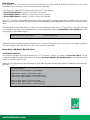
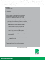
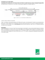
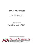
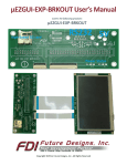
The CPU offloads the work of refreshing the TFT panel to the external DMA (Ex-DMA) controller inside the MCU (Figure 1). The Ex-DMA
takes control of the 16-bit external bus by driving the address lines and controlling the read strobe to the external RAM. The RAM frame
buffer outputs a 16-bit data word for one pixel of RGB data. The MCU’s timer unit clocks the RGB pixel data into the TFT panel. This
process is repeated for each RGB pixel, once per frame. Driving the TFT-LCD using the external DMA frees up the CPU to spend the
bulk of its processing time on the application software.
The MCU can access internal memory and peripherals using its internal bus
while the TFT panel is being refreshed externally. There is approximately 5%
loading on the CPU during normal operation as the Ex-DMA unit and the CPU
have minimal interaction. This frees up the CPU to run the application and
periodically write new image data to the external RAM frame buffer.
* RX Series Direct LCD Design Guide, p.17, Renesas Electronics Corporation
Figure 1. Direct drive block diagram*
www.FutureElectronics.com
LCD Selection
When selecting a TFT LCD for a Renesas Direct Drive RX62N solution, choose any panel up to WQVGA resolution (480x272) at 16 bpp
color depth. The LCD can be any size or orientation (portrait or landscape).
Future Electronics, together with FDI, offers three Direct Drive TFT-LCD solutions:
• Future/FDI RX62N Demo: including 3.5” QVGA NLT LCD Portrait
• FDI DK-43WQT-RX62N: including 4.3” WQVGA Tianma LCD Landscape
• FDI DK-47WQT-RX62N: including 4.7” WQVGA Tianma LCD Landscape
These TFT LCD panels have integrated touchscreens and there are preset LCD firmware configurations available for each. If one of the
above is not chosen for the design, firmware parameters should be modified as described below in the Direct Drive LCD device specific
focus.
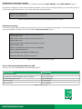
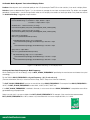
The remainder of the white paper discusses a Direct Drive firmware design based on the 3.5” NLT NL2432HC22-41B QVGA (240x320)
LCD. To select an LCD panel in firmware (and activate its preset configuration) modify the UEZ_DEFAULT_LCD_CONFIG define in file:
Config_App.h as shown below (Figure 2):
#define UEZ_DEFAULT_LCD_CONFIG
NLT_NL2432HC22-41B
Figure 2. Select LCD used in the Project in file:Config_App.h
Additional firmware may be required when integrating a new LCD panel. For example, the NLT NL2432HC22-41B requires initialization
of its internal registers after reset. Refer to the Tips & Tricks section for more details.
Direct Drive LCD Device Specific Focus
LCD Timing Parameters
The firmware to configure the timing parameters for the TFT-LCD panel is found in uEZ project file: DirectLCD_CNF().h. The part
number of the target LCD panel is in parentheses, for example: DirectLCD_CNF(NLT_NL2432HC22-41B).h is the configuration file for
the NLT NL2432HC22-41B TFT-LCD.
Modify the LCD timing parameters: dot clock frequency, pulse width, back porch and front porch (Figure 3) according to the manufacturer’s
datasheet.
//Dot Clock Frequency
#define DOT_CLOCK_FREQUENCY_DATA 6000000L
#define H_DOT_PULSE 8 // Horizontal pulse width
#define H_DOT_BACK_PORCH 3 //Horizontal back porch
#define H_DOT_FRONT_PORCH 4 // Horizontal front porch
#define V_LINES_PULSE 2 // Vertical pulse width
#define V_LINES_BACK_PORCH 1 // Vertical back porch
#define V_LINES_FRONT_PORCH 1 //Vertical front porch
Figure 3. LCD Timing Parameters, file: DirectLCD_CNF(NLT_NL2432HC22-41B).h
www.FutureElectronics.com
LCD Resolution & Orientation Settings
To configure the screen resolution, modify the LCD resolution parameters H_DOT_DISPLAY and V_LINES_DISPLAY (Figure 4).
For example, to configure the Direct Drive firmware for resolution: 240x320 pixels, modify the parameters as shown below (Figure 4).
The firmware may be used to drive an LCD in either landscape or portrait orientation.
#define H_DOT_DISPLAY 240
#define V_LINES_DISPLAY 320
Figure 4. Resolution 240x320 Portrait, file: DirectLCD_CNF(NLT_NL2432HC22-41B).h
LCD Interface Settings
The interface settings specify the port and pin assignments for vsync, hsync dot clock and backlight. The Ex-DMA channel and timer
unit are also specified. The code is found in uEZ project file: DirectLCD_CN().h (Figure 5).
#define VSYNC_PORT 2 // VSYNC connected to Port 2, Pin 4
#define VSYNC_PIN 4
#define HSYNC_PORT 3 //HSYNC connected to Port3, Pin 6
#define HSYNC_PIN 2
#define DOTCLK_PORT 5 //DOTCLK connected to Port 5 Pin 6
#define DOTCLK_PIN 6
#define LCD_BACKLIGHT_PORT 9 //Power to LCD Backlight
#define LCD_BACKLIGHT_PIN 3
#define EXDMAC_DD EXDMAC0 // ExDMA Channel
#define DD_TMR_MTU // Specify timer unit used
Figure 5. Interface Settings, file: DirectLCD_CNF().h
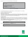
Turn on LCD, Control Backlight and Access LCD
To turn on the LCD and backlight refer to the table below (Table 1):
LCD Function
uEZ Routine
Access the LCD device
UEZLCDOpen()
Get a pointer to the frame memory in the LCD display
UEZLCDGetFrame()
Control the backlight intensity
UEZLCDBacklight()
Turn the LCD on
UEZLCDOn(lcd)
Turn the LCD off
UEZLCDOff(lcd)
Table 1. LCD Access API
www.FutureElectronics.com
Sample code to access the LCD and control the backlight is shown below (Figure 6).
T_uezDevice lcd;
T_pixelColor *pixels;
if (UEZLCDOpen(“LCD”, &lcd) == UEZ_ERROR_NONE) {
UEZLCDGetFrame(lcd, 0, (void **) &pixels);
UEZLCDBacklight(lcd, 0); //set backlight off
UEZLCDOn(lcd);
UEZLCDBacklight(lcd, 255); //set backlight to max intensity
}
Figure 6. Access LCD and Turn On Backlight
This ends the discussion of the Direct Drive LCD device specific focus. The application specific focus is discussed below.
Direct Drive LCD Application Specific Focus
Display Pixels, Lines, Boxes & Text
The uEZ provides a graphics library for drawing pixels, lines, boxes and text. First, open and draw a window by calling the uEZ
window_open routine. A window is defined by its left, top coordinate and right, bottom coordinate and border width. Choose the window
background color. Call uEZ drawing routines to draw pixels, lines, boxes and shapes. Call uEZ font routines to display text, control font
type, size and transparency. Pen color, text color and fill color can also be modified dynamically.
Icons/Buttons Display
To add an application icon to the project, first create a bitmap image in Targa format using an Image Editor. Save the image to file:
NewIcon.tga and copy it to the “Images” folder. In this folder there is a batch file called: convert.bat that converts the binary .tga file
into a C variable definition. It contains the binary data in a format that can be compiled by the uEZ. Run the batch file: convert.bat to
create the file: NewIcon.h. Add the icon to the HEW project by right clicking on the project name in the HEW Project Explorer and select
“Add Files.” Navigate to the images folder and select file: NewIcon.h.
From the Project Explorer open the file: UDCImages.c, find the list of #include directives and add the line:
#include “images/NewIcon.h”
Go back to the Project Explorer and open the file: UDCImages.h, then add:
extern const TUInt8 G_newIcon[];
www.FutureElectronics.com
Build the project to add the application icon to the project. Use the code shown below (Figure 7) to display the application icon:
static const T_appMenuEntry mainmenu_entries[] = {
{ “Direct Drive Demo”, DisplayDemo, G_newIcon, 0 },
{ 0 },
};
static const T_appMenu mainmenu = {
PROJECT_NAME “ “ VERSION_AS_TEXT “ - Main Menu”,
mainmenu_entries,
EFalse, // cannot exit
};
AppMenu(&mainmenu);
Figure 7. Display Icon on LCD
When the icon represented by G_newIcon is pressed on the touchscreen the application calls function: DisplayDemo().
Touchscreen Input (4-Wire Resistive)
The uEZ provides an API for the touchscreen with a task that polls status and generates events placed on the queue. To get access
to the touchscreen, add an array of type T_choice that holds information about each icon size and type. In the example shown below
(Figure 8), three icons are displayed on the LCD. The icons are: G_exitIcon to exit the menu, G_upArrIcon to increase animation speed
and G_downArrIcon to decrease animation speed. Each icon has a function associated with it that is called when the icon is pressed.
For example, when the user presses the G_exitIcon, the touchscreen senses the input and calls function: DD_Exit().
static const T_choice G_ddChoices[] = { // Array to store the icons, their locations, and the functions they call
{ DD_COLUMN_1_CTRL, 20, DD_COLUMN_1_CTRL+DD_BUTTON_WIDTH-1, 50, “”, DD_Exit, G_exitIcon },
{ DD_COLUMN_1_CTRL, 55, DD_COLUMN_1_CTRL+DD_BUTTON_WIDTH-1, 85, “”, DD_IncSpd, G_
upArrIcon },
{ DD_COLUMN_1_CTRL, 85, DD_COLUMN_1_CTRL+DD_BUTTON_WIDTH-1, 115, “”, DD_DecSpd, G_
downArrIcon },
{ 0, 0, 0, 0, 0 }
};
Figure 8. Array to Store Icons Location & Associated Function when Pressed
To use the touchscreen, declare a queue to catch the touchscreen events and a handle to the touchscreen (Figure 9).
T_uezQueue queue; //queue to catch the touch screen events
T_uezDevice ts; //handle to touch screen
Figure 9. Touchscreen Queue
www.FutureElectronics.com
The code to sense the touchscreen input is shown below (Figure 10). The UEZQueueCreate() function creates a queue for the
touchscreen. Open and initialize the touchscreen device and pass in the queue by calling function: UEZTSOpen(). The ChoicesDraw()
function draws the icons in the G_ddChoices array and checks the touchscreen event on each iteration of the while loop. When an icon
is touched, its corresponding function is called. To disable touchscreen input, close the touchscreen and delete the queue by calling
functions: UEZTSClose(), UEZQueueDelete().
typedef struct {
T_uezTSFlags iFlags;
TInt32 iX;
TInt32 iY;
TUInt32 iPressure;
} T_uezTSReading;
void DisplayDemo(const T_choice *aChoice)
{
T_uezDevice lcd; // uEZ Device Type handle to the display
T_pixelColor *pixels; // pointer to the screen (an array of pixels)
T_uezQueue queue; // Queue to catch Touch Screen events
T_uezDevice ts; // uEZ Device Type handle to Touch Screen
//UEZQueueCreate creates a queue and returns point to the queue
if (UEZQueueCreate(1, sizeof(T_uezTSReading), &queue) == UEZ_ERROR_NONE) {
// Open up the touchscreen and pass in the queue to receive events
if (UEZTSOpen(“Touchscreen”, &ts, &queue)==UEZ_ERROR_NONE) {
// Open the LCD and get the pixel buffer
if (UEZLCDOpen(“LCD”, &lcd) == UEZ_ERROR_NONE) {
//Returns a pointer to the frame memory in the LCD
UEZLCDGetFrame(lcd, 0, (void **)&pixels);
SUIHidePage0(); // This hides the page while we are redrawing
//Draw the icons selected in the G_ddChoices array
ChoicesDraw(&G_aTsWindow, G_ddChoices); // Draw choices
SUIShowPage0(); // Show the page now that everything has been drawn
while (!G_ddExit) {
// Wait for a touchscreen event or timeout
ChoicesUpdate(&G_aTsWindow, G_ddChoices, queue, 100);
//application code here
}
UEZLCDClose(lcd); // End access to the LCD display
}
UEZTSClose(ts, queue); // Close a previously opened touchscreen device
}
UEZQueueDelete(queue); // Close the Touch Screen queue
}
}
Figure 10. Sense Touchscreen Input
www.FutureElectronics.com
Animate Screen Objects
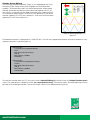
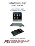
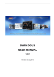
The “Bouncing Diamonds Application” (Figure 11) was developed by the Future
Electronics System Design Center (SDC) to highlight the RX62N direct drive
capability. The firmware discussed in this section demonstrates variable speed
animation of two bouncing diamond sprites (red & blue) together with CPU run
time statistics. User buttons control speed of animation (slow, medium and fast).
As the animation speed increases, the CPU IDLE time decreases. At the slowest
animation speed the CPU IDLE time is above 80%, while at the fastest animation
speed the CPU IDLE time is above 50%.
Figure 11. Bouncing Diamonds
Application
Each diamond animation is implemented as a FreeRTOS task. The tasks are assigned identical priority and time to complete as many
trajectory calculations as possible (Figure 12).
UEZTaskCreate(
(T_uezTaskFunction)vUpdateFPUShape,
“FPU”,
UEZ_TASK_STACK_BYTES(128),
(void *)0,
UEZ_PRIORITY_NORMAL,
FPUHandle);
UEZTaskCreate(
(T_uezTaskFunction)vUpdateNoFPUShape,
“NoFPU”,
UEZ_TASK_STACK_BYTES(128),
(void *)0,
UEZ_PRIORITY_NORMAL,
NoFPUHandle);
Figure 12. Create FreeRTOS Tasks to Perform Animation
To create the animation effect, the FPU task calls function: vUpdateFPUShape() to initialize a timer for TaskAppTimerMsecCount
msecs. The shape position is updated in function: fpu_shapeUpdatePosition(). The previous shape is erased by redrawing it with the
pen color set to the background color. Then the new shape is drawn at the updated position (Figure 13).
www.FutureElectronics.com
#define RADIUS_VERT
10 //Diamond vertical radius
SHAPE fpuShape ; //current shape position
SHAPE fpuShapePrev; //previous shape position
TUInt32 vUpdateFPUShape(T_uezTask aMyTask, void *aParams) //RTOS Task
{
PARAM_NOT_USED(aMyTask);
PARAM_NOT_USED(aParams);
for ( ;; )
{
if (enableUpdateFPUShape) {
//save fpuShape previous position
fpuShapePrev = fpuShape;
//Move shape using hardware FPU
//TaskAppTimerMsecCount = TimeToMoveShape;
while( TaskAppTimerMsecCount>0 ) { //decrement count in another task
fpu_shapeUpdatePosition (&fpuShape) ; //move the shape
}
//erase fpuShape in previous position
set_pen_color(&G_aTsWindow, BLACK); //Sets the pen color
set_fill_color(&G_aTsWindow, BLACK ); //Sets the fill color
put_diamond(&G_aTsWindow,
(int) fpuShapePrev.x, //x : Virtual X position of diamond
(int) fpuShapePrev.y, //y : Virtual Y position of diamond
RADIUS_HORIZ,
//rx : Radius for horizontal
RADIUS_VERT);
//ry : Radius for vertical
//draw fpu shape
set_pen_color(&G_aTsWindow, BLACK); //Sets the pen color
set_fill_color(&G_aTsWindow, RED ); //Sets the fill color
put_diamond(&G_aTsWindow,
(int) fpuShape.x,
//x : Virtual X position of diamond
(int) fpuShape.y,
//y : Virtual Y position of diamond
RADIUS_HORIZ,
//rx : Radius for horizontal
RADIUS_VERT);
//ry : Radius for vertical
}
UEZTaskDelay(TaskIdleTime);
}
}
return 0;
Figure 13. FreeRTOS Task to Animate a Shape
The red diamond animation trajectory is calculated with floating point math enabled (FPU), simply by changing the compiler options to
generate native floating point code, causing it to bounce much faster (approximately 3.5 times faster than the blue diamond). The blue
diamond trajectory is calculated with native floating point code generation turned off by the compiler (NOFPU).
The FreeRTOS API collects real-time data on the absolute & percentage of CPU processing time used by each task. The CPU Stats are
displayed in the upper right hand corner of the TFT-LCD highlighting percentage of CPU IDLE time. This is a useful feature to enable in
FreeRTOS to measure system performance.
Animation requires frequent access to the frame buffer during vertical blanking. Refer to the Tips & Tricks section for more details.
www.FutureElectronics.com
Tips & Tricks
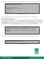
#1: How to Initialize TFT-LCD Internal Registers via SPI
Some LCDs may require initialization of internal registers. For example, the NL2432HC22-41B LCD requires data be written into the
internal registers after applying /RESET from serial interface pins (/CS, SCL and SI).
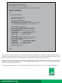
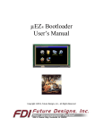
The RX62N System Control Register 0, bit b1 controls whether the external bus is enabled or disabled (Figure 14).
Figure 14. System Control Register 0 (SYSCR0)2
2
RX62N Group, RX621 Group User’s Manual: Hardware, p. 124, R01UH0033EJ0110 Rev.1.10, Renesas Electronics Corporation
Problem: The SPI Interface requires access to the external bus to initialize the LCD internal registers. On startup, the uEZ function:
UEZBSPSDRAMInit() enables the external bus (Figure 15). When the external bus is enabled, the SPI interface /CS cannot go to the
LOW state and the transfer will not occur.
www.FutureElectronics.com
/*---------------------------------------------------------------------------*
* Routine: UEZBSPSDRAMInit
*---------------------------------------------------------------------------*
* Description:
*
Initialize the external SDRAM.
*---------------------------------------------------------------------------*/
void UEZBSPSDRAMInit(void)
{
TUInt32 delay;
// Configure port pins -------------// Enable On Chip ROM & External BUS
SYSTEM.SYSCR0.WORD = 0x5A03;
Figure 15. UEZBSPSDRAMInit() Function Enables External BUS
Solution: The HAL (Hardware Abstraction Layer) is a layer of firmware that controls the hardware directly. The function: ISPIConfigure()
is a HAL function that configures the SPI interface (Figure 16). Before starting the SPI transfer, disable the external bus by setting the
SYSTEM.SYSCRO.WORD to 0x5A01. This clears SYSCRO Bit b1. Then write data to the LCD Registers via the SPI interface by
calling function: ISPIWriteCommands(). When the SPI transfer is complete, set SYSTEM.SYSCRO.WORD to 0x5A03 to enable the
external bus for normal LCD operation.
static T_uezError ISPIConfigure(T_NL2432HC22_41KWorkspace *p)
{
T_uezError error = UEZ_ERROR_NONE;
error = UEZSPIOpen(“SPI1”, &p->iSPI); //open the SPI1 interface
if (!error) {
SYSTEM.SYSCR0.WORD = 0x5A01; //disable External Bus
if (!error) {
UEZTaskDelay(1);
//Power ON Sequence 5-45
error = ISPIWriteCommands(p, G_lcdPowerOn_a);
if (!error) {
//Sequence 46 - 30 microsecond min. wait
UEZTaskDelay (1);
//Sequence 47 - Data input start NOP
//Sequence 48
error = ISPIWriteCommands(p, G_lcdPowerOn_b);
if (!error) {
//Sequence 49 - 20 ms min. wait
UEZTaskDelay(25);
//Sequence 50
error = ISPIWriteCommands(p, G_lcdPowerOn_c);
}
}
}
SYSTEM.SYSCR0.WORD = 0x5A03; //enable External Bus
UEZSPIClose(p->iSPI); //close the SPI interface
}
return error;
}
Figure 16. Disable External Bus Prior to SPI Transfer
www.FutureElectronics.com
#2: Double Buffer Dynamic Text to Avoid Display Flicker
Problem: When dynamic text is refreshed rapidly on the LCD (for example: FreeRTOS run time statistics) it can result in display flicker.
Solution: Create a double buffer (Figure 17) in the software to manage the text input and output buffer. The buffers are swapped
periodically. Dynamic data is sent to the input buffer while the LCD displays the contents of the output buffer. Every fixed time interval
the doublebufferFlag is toggled to swap the buffers.
//toggle doublebufferFlag in application code
short doublebufferFlag = 0; //0: buffer1 = input, buffer2 = output
//1: buffer1 = output, buffer2 = input
/double buffer 1: 2 dimensional array of strings
char buffer1Stats[MAX_NUM_TASK_STRINGS][MAX_TASK_STRING_SIZE];
//double buffer 2: 2 dimensional array of strings
char buffer2Stats[MAX_NUM_TASK_STRINGS][MAX_TASK_STRING_SIZE];
//get pointer to input buffer
static char *getDoubleBufferPtrIn(int index)
{
if (!doublebufferFlag) //flag to choose input buffer
return &buffer1Stats[index][0]; //doublebufferFlag==0: buffer1 = input
else
return &buffer2Stats[index][0]; //doublebufferFlag==1: buffer2 = input
}
//get pointer to output buffer
static char *getDoubleBufferPtrOut(int index)
{
if (doublebufferFlag) //flag to choose output buffer
return &buffer1Stats[index][0]; //doublebufferFlag==1: buffer1 = output
else
return &buffer2Stats[index][0]; //doublebufferFlag==0: buffer2 = output
}
Figure 17. Double Buffer Text Strings to Avoid Display Flicker
#3: Crystal, Dot Clock Frequency & Bclk Frequency
When choosing the LCD for the design, verify the DOT_CLOCK_FREQUENCY specified by the manufacturer and choose the crystal
accordingly.
For the RX62N, BCLK_FREQUENCY = Crystal Frequency * (8) / (1 or 2 or 4 or 8);
(For more information, refer to p. 238 of the RX62N Group, RX621 Group User’s Manual: Hardware).
The DOT_CLOCK_FREQUENCY must be an even divisor of the BCLK_FREQUENCY. For example if the BCLK_FREQUENCY is
48 MZ, the DOT_CLOCK_FREQUENCY can be 24MH, 12MHZ, 6 MHZ, 4MHZ, etc.
If the DOT_CLOCK_FREQUENCY, initialized in firmware, is not an even divisor of BCLK_FREQUENCY a compilation error will be
generated during the project build.
Select a crystal that it is an even multiple of the DOT_CLOCK_FREQUENCY. For example, if the manufacturer recommended DOT_CLOCK_FREQUENCY is 6 MHz, choose a crystal oscillator that is an even multiple of 6MHz, i.e. 12MHz.
www.FutureElectronics.com
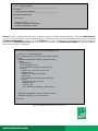
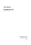
#4: CPU Access to Frame Buffer
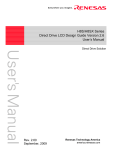
The ExDMA and CPU share access to the external memory frame buffer. For approximately 50% of the LCD refresh period, the ExDMA
moves data from the SRAM to the LCD. During this time the CPU tasks that access the external memory should be suspended. After
the ExDMA transfer is finished, the CPU can access the frame buffer to update the LCD display (Figure 18).
Figure 18. CPU Access to Frame Buffer after ExDMA Transfer
*Courtesy Renesas Electronics Corporation
There is no hardware synchronization between the ExDMA and CPU access to the frame buffer. The effect of unsynchronized frame
buffer access may be stalling of the CPU core while it waits for the ExDMA transfer to end. This will result in undesired screen artifacts.
To resolve this issue in firmware, wait for the LCD_BusActive flag to be cleared (indicating ExDMA transfer is finished) before modifying
the contents of the frame buffer.
Conclusion
The essential elements of a successful Direct Drive firmware design are presented. By using the recommended hardware and software
libraries, the developer can shorten the Direct Drive firmware design cycle considerably. Renesas provides the GAPI library and Direct
Drive LCD low-level drivers to control the timing signals to the TFT-LCD free of charge. The uEZ GUI Software and FreeRTOS are open
source software tools compatible with Renesas RX62N Direct Drive TFT-LCD solutions, providing advanced graphical display effects for
a cost effective design.
www.FutureElectronics.com
Direct Drive Demo Hardware
n Future Electronics/FDI 3.5” NLT RX62N: demo including LCD board, baseboard and SOMDIMM module
- Can be borrowed through your local Future Electronics representative
n FDI 4.3” Tianma: demo including LCD board, baseboard and SOMDIMM module
- Can be purchased using the following part number: DK-43WQT-RX62N
- Can be borrowed through your local Future Electronics representative
n FDI 4.7” Tianma: demo including LCD board, baseboard and SOMDIMM module
- Can be purchased using the following part number: DK-47WQT-RX62N
- Can be borrowed through your local Future Electronics representative
n 3.5” NLT LCD Carrier Board: Carrier Board for NLT 3.5in TFT-LCD (240x320). Designed by Future Electronics System Design Center
(SDC) as part of the Future/FDI 3.5in NLT RX62N demo as stated above. Reference design available upon request.
n NLT 3.5” TFT-LCD (240x320): NL2432HC22-41B Portrait
Technical Resources
n www.FutureElectronics.com/Renesas
n www.rxmcu.com/USA
n www.teamfdi.com
n The uEZ source code and documentation can be downloaded from www.sourceforge.net/projects/uez
n FreeRTOS is available from http://www.freertos.org/
Renesas Electronics America is the exclusive sales and marketing channel in the Americas for LCD Modules from NLT Technologies.
www.FutureElectronics.com