Transcript
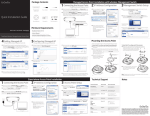
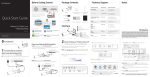
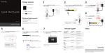
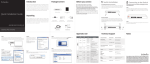
Package Contents
Access Point
2.4 GHz Detachable Antennas x 3
5 GHz Detachable Antennas x 3
Power Adapter
1 Connecting the Access Point
2 IP Address Configuration
A)Connect one end of the Ethernet cable into the main LAN port (PoE)
of the Access Point and the other end to the AP Ethernet port on the
PoE injector.
B)Connect the Power Adapter to the DC-IN port of the PoE injector and
plug the other end in to an electrical outlet.
C) Connect the second Ethernet cable into the LAN port of the PoE injector
and the other end to the Ethernet port on the computer.
D)Screw on the provided antennas to the device as shown in illustration below.
A) Once your computer is on, ensure
that your TCP/IP is set to On or
Enabled. Open Network
Connections and then click Local
Area Connection. Select Internet
Protocol Version 4 (TCP/IPv4)
and then click on the Properties
button.
Note: The Access Point supports both IEEE 802.3at PoE (Power over
Ethernet) or the included power Injector. You may use either one as the
power source. DO NOT use both at the same time.
Quick Installation Guide
Wall Mounting Kit
Ground Cable
A)To configure the Access Point, open a web browser. In the address bar
of the web browser, enter 192.168.1.1 and hit enter.
B)A login screen will appear. By default, the username of the Access Point
is admin and the password is admin. Enter the current username and
password of the Access Point and then click Login.
2.4 GHz
PoE Injector
3 Access Point Setup
5 GHz
D
To Computer
Pole Mounting Kit
ENH900EXT | ENH1750EXT
version l.0
Quick Installation
Guide
Minimum Requirements
Broadband Internet Service
(Cable or DSL Modem)
+Internet Browser
(Internet Explorer, Safari, Firefox, Chrome)
+
Dual Band, Long Range
Wireless Outdoor Access Point
4 Switching Modes
A) This device can operate in the following modes: Access Point, Mesh and WDS.
B) Select the Operation Mode under “Network”, “Wireless” tab.
C
A
D
5 GHz
B) If your PC is already on a network,
ensure that you have set it to a
Static IP Address on the interface.
(Example: 192.168.1.10 and the
Subnet Mask address as
255.255.255.0.
A
B
* Your model number may be different in the web browser interface.
2.4 GHz
Technical Support
Wall Mounting The AP
A) Mark the four locations of the mounting holes on the flat mounting
surface.
C) Place the lock and flat washers on the four hex cap screws and drive
the screws to attach bracket to the back of the Access Point.
D) Tighten the flat washers to secure the bracket to the
mounting surface.
Country of Purchase
Service Center
Service Information
North America
Canada
[email protected]
Toll Free: (+1) 888 397 2788
Local: (+1) 905 940 8181
www.engeniustech.com
Los Angeles, USA
[email protected]
Toll Free: (+1) 888 735 7888
Local: (+1) 714 432 8668
Central & South America
Miami, USA
[email protected]
Miami: (+1) 305 887 7378
Sao Paulo, Brazil: (+55) 11 3957 0303
D.F, Mexico: (+52) 55 1163 8894
Europe
Netherlands
[email protected]
(+31) 40 8200 887
Africa
CIS
Middle East
Russia
Dubai, UAE
[email protected]
Toll Free:
U.A.E.:800-EnGenius
800-364-364-87
General: (+971) 4 357 5599
Asia
Oceania
Singapore
www.engeniustech.com.sg/e_warranty_form
[email protected]
Toll Free:
Singapore: 1800 364 3648
Others
Taiwan, R.O.C
[email protected]
www.engeniuscanada.com
B) Drill a 37mm deep 8mm hole in the markings and hammer the bolts
into the openings.
A
es.engeniustech.com
pg.engeniustech.com
www.engeniusnetworks.eu
B
C) Click on the Save button after you have modified the setting. Click the
Changes button, then click Apply button to apply all changes
you have made.
www.engenius-me.com
www.engeniustech.com.sg
www.engeniusnetworks.com
Notes
Pole Mounting The AP
A) Place the lock and flat washers on the four hex cap screws and drive
the screws to attach bracket to the back of the Access Point.
B) Drive the four round head screws to attach the Pole Mount Bracket to
the bracket.
C) Thread the open end of the Pole Strap through the two tabs on the
Pole Mount Bracket .
D) Lock and tighten Pole Strap to secure Pole Mount Bracket to the pole.
Horizontal Placement
Vertical Placement
Horizontal Placement
Horizontal Placement
Maximum data rates are based on draft IEEE 802.11ac and/or IEEE 802.11 standards. Actual
throughput and range may vary depending on many factors including environmental conditions,
distance between devices, radio interference in the operating environment, and mix of devices in
the network. Features and specifications subject to change without notice. This device complies
with Part 15 of the FCC Rules. Operation is subject to the following two conditions: (1) this device
may not cause harmful interference, and (2) this device must accept any interference received,
including interference that may cause undesired operation. Trademarks and registered trademarks
are the property of their respective owners. For United States of America: Copyright ©2013 EnGenius
Technologies, Inc. All rights reserved.