Transcript
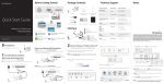
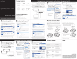
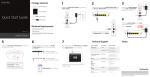
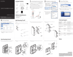
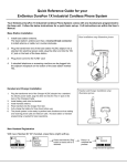
Introduction
Package Content
Power-over-Ethernet (PoE) technology brings new capability and device
1
Mode
Power
Fault
PoE
Max
2
3
5
4
6
7
8
1
Link/Act
Mode
Power
LAN
Mode
PoE
Max
Factory
Reset
2
3
5
4
6
7
8
Link/Act
LAN
Mode
Fault
PoE
Mode
LED Mode
Selector
PoE
Mode
LED Mode
Selector
Factory
Reset
expansion to network deployments. IP cameras, indoor wireless access
1
1
Mode
Power
PoE
Max
1
Mode
Power
Fault
PoE
Max
2
3
4
5
6
7
2
3
5
4
6
7
8
Link/Act
LAN
Mode
Fault
PoE
Mode
LED Mode
Selector
Factory
Reset
8
Link/Act
LAN
Mode
PoE
Mode
LED Mode
Selector
Factory
Reset
EnGenius Switch
Quick Installation
Guide
1
Mode
Power
Fault
PoE
Max
2
3
4
5
6
7
8
Link/Act
LAN
Mode
PoE
Mode
LED Mode
Selector
Factory
Reset
Unpacking
PoE
Mode
LED Mode
Selector
1
Mode
Power
Fault
PoE
Max
2
3
5
4
6
7
1
3
5
4
6
7
Mode
Power
PoE
Max
PoE
Mode
LED Mode
Selector
PoE
Mode
LED Mode
Selector
1
Mode
PoE
Max
2
3
4
5
6
7
Step 1
Connect the supplied Power Adapter (cord) to the Switch and plug the
other end into an electrical outlet. Turn the Power Switch on the back of
the device to the ON Postion. Verify the Power LED indicator is lit on the
Switch.
PoE
Mode
LED Mode
Selector
8
Link/Act
Factory
Reset
8
Mode
LAN
Mode
PoE
Mode
LED Mode
Selector
Factory
Reset
consult the packing list below to make sure all the items are present and
2
3
5
4
Ground Screw Kit
Mode
Power
Fault
PoE
Max
(EGS2108P & EGS2110P)
6
7
8
1
Link/Act
2
3
5
4
6
7
PoE
Max
PoE
Mode
LED Mode
Selector
PoE
Max
1
Fault
PoE
Max
1
Mode
Power
2
3
5
4
6
7
Mode
Power
2
3
5
4
PoE
Max
PoE
Mode
LED Mode
Selector
6
7
6
1
Mode
Power
6
7
8
Factory
Reset
2
3
4
5
6
7
8
3
4
5
6
7
8
Link/Act
LAN
Mode
PoE
Max
7
PoE
Mode
LED Mode
Selector
8
Factory
Reset
5
4
PoE
Mode
LED Mode
Selector
Factory
Reset
PoE
Mode
LED Mode
Selector
8
Link/Act
Factory
Reset
8
2
3
5
4
6
Link/Act
1
2
Link/Act
LAN
Mode
Factory
Reset
7
8
3
4
5
6
7
8
Step 4B
If your Computer is already on a
network, ensure that you have
set it to a Static IP Address on the
interface.
(Example: 192.168.0.10 and
the Subnet Mask address as
255.255.255.0.
Technical Support
Step 5
Open a web browser on your computer. In the address bar of the web
browser, enter 192.168.0.239 and enter.
Fault
LED
Indicator
LED
Color
Status
Power
Green
Solid Light
Power On
Light Off
Power Off
Fault
Amber
PoE
Max
Solid Light
Meaning
Error
2
3
4
5
6
7
Notes
1
Light Off
Step 7
The switch Web-based Graphical User Interface (GUI) page screen
will appear. Use the switch Web-based Graphical User Interface (GUI)
management to perform basic switch configuration and monitoring.
PoE Max
Amber
Normal Behavior
Solid Light
The PoE device’s output power
has exceeded total PoE limit.
No additional devices can be
powered on via PoE.
Light Off
Additional devices may still be
added
LAN Mode
Green
Solid Light
The device is connected and the
port successfully
PoE Mode
Green
Solid Light
The PoE powered device is
connected and the port is
supplying power successfully
LAN Mode
PoE Mode
Link/Act
Green
Solid Light
A valid 1000 Mbps link is
established on the port.
Amber
Solid Light
A valid 10/100 Mbps link is
established on the port.
Off
Light Off
Green
Solid Light
Power is being supplied from
the PoE switch.
Amber
Solid Light
Error
Off
Light Off
Green
Solid Light
No link is established on the port
No Power
A valid link is established on
the port
Blinking
Packet transmission on the port
Off
No link is established on the port
Mode
Power
2
Link/Act
LAN
Mode
Fault
PoE
Max
PoE
Mode
LED Mode
Selector
Factory
Reset
8
Link/Act
LAN
Mode
PoE
Mode
LED Mode
Selector
1
Factory
Reset
Service Center
Service Information ng
North America
Canada
[email protected]
Toll Free: (+1) 888 397 2788
Local: (+1) 905 940 8181
www.engeniuscanada.com
Mode
Power
Country of Purchase
PoE
Max
PoE
Mode
LED Mode
Selector
www.engeniustech.com
Los Angeles, USA
[email protected]
Toll Free: (+1) 888 735 7888
Local: (+1) 714 432 8668
Central & South America
Miami, USA
[email protected]
Miami: (+1) 305 887 7378
Sao Paulo, Brazil: (+55) 11 3957 0303
D.F, Mexico: (+52) 55 1163 8894
Europe
Netherlands
[email protected]
(+31) 40 8200 887
Africa
CIS
Middle East
Russia
Dubai, UAE
[email protected]
Toll Free:
U.A.E.:800-EnGenius
800-364-364-87
General: (+971) 4 357 5599
Asia
Oceania
Singapore
www.engeniustech.com.sg/e_warranty_form
[email protected]
Toll Free:
Singapore: 1800 364 3648
Others
Taiwan, R.O.C
[email protected]
es.engeniustech.com
pg.engeniustech.com
www.engeniusnetworks.eu
3
5
4
6
7
8
Factory
Reset
1
Mode
Power
PoE
Max
2
Link/Act
LAN
Mode
Fault
Fault
Factory
Reset
Step 4A
Once your computer is on, ensure
that your TCP/IP is set to On
or Enabled. Open Network
Connections and then click Local
Area Connecton. Select Internet
Protocol Version 4 (TCP/IPv4).
Mode
Power
Step 6
A login screen will appear. By default, the password is password. Enter
the current password of the Switch and then click Login.
LED
Per Device
PoE
Mode
LED Mode
Selector
LED
Per Copper Port
PoE
Max
Mode
5
Fault
PoE
Mode
LED Mode
Selector
1
1
Mode
LAN
Mode
Fault
PoE
Mode
LED Mode
Selector
4
3
Factory
Reset
Power
PoE
Max
3
2
Link/Act
Link/Act
Step 3
Connect one end of a Category 5/6 Ethernet cable into the Gigabit
(10/100/1000) Ethernet port on the switch front panel and the other end
to Ethernet port on the computer. Verify that the LED on Ethernet ports of
the switch are green.
Fault
Mode
LAN
Mode
Appendix: LED
Power
8
LAN
Mode
Fault
8
2
Link/Act
LAN
Mode
Fault
(EGS5110P Only)
7
LAN
Mode
PoE
Max
1
Mode
Power
Rack Mount Kit
6
Step 2
Wait for the switch to complete boot up. It might take several minutes for
the switch to complete boot up.
1
Power Cord
5
8
Fault
(EGS5110P Only)
4
Factory
Reset
Power
Business PoE Switches
3
Link/Act
Factory
Reset
version l.0
8
PoE
Mode
LED Mode
Selector
LAN
Mode
EGS2108P | EGS2110P | EGS5110P
7
2
Link/Act
LAN
Mode
Fault
your local EnGenius reseller for replacement.
6
Mode
Power
B) Rack Installation
To mount the switch in a rack, attached the included rack mounting
brackets to the switch. Then connect the switch to the rack, securing
the mounting brackets to the rack. The switch can be mounted in an EIA
standard size, 13-inch rack, which can be placed in a wiring closet with
other equipment.
1
(EGS2108P & EGS2110P)
Connecting the Devices to the Switch and Managing the Switch
using a Web Browser
8
Link/Act
Open the shipping carton and carefully unpack its contents. Please
(EGS2108P & EGS2110P)
7
LAN
Mode
Fault
1
slightly different. If any item is found missing or damaged, please contact
6
Factory
Reset
PoE
Max
Wall Mount Kit
5
4
LAN
Mode
Fault
Power Adapter
3
Factory
Reset
Power
Power
undamaged. Please note that the model you have purchased may appear
2
Link/Act
LAN
Mode
Fault
Factory
Reset
2
2 Connecting to the Switch
A) Installing the Switch on a Flat Surface
Install the switch on a flat surface such as a desktop or shelf, attach the
rubber feet on the bottom at each corner of the switch. The rubber feet
cushion the switch from shock or vibration, and secure space between
devices when stacking.
8
Link/Act
LAN
Mode
PoE
Max
are capable of receiving their power over Ethernet cabling. These EnGenius
Quick Installation Guide
Mode
Fault
points, VoIP (Voice-over- IP) phone systems and many other client devices
network through its simple web-based Graphical User Interface (GUI).
•Do not place heavy objects on the Switch.
•Do not expose the switch to direct sunlight.
•Make sure that there is adequate space (at least 2 inches)
for proper heat dissipation around the Switch. Please do not
cover the ventilation holes on all sides of the Switch.
•Install the Switch in a fairly cool and dry environment.
•Install the Switch in a site free from strong electromagnetic
source.
•Visually inspect the power jack and make sure that it is fully
secured to the power adapter.
Power
Switches provide management with tools to configure and control the
1 Switch Installation
Before you connect
2
3
4
5
6
7
8
Link/Act
LAN
Mode
PoE
Mode
LED Mode
Selector
Factory
Reset
www.engenius-me.com
www.engeniustech.com.sg
www.engeniusnetworks.com
Maximum data rates are based on IEEE 802.3ab standards. Actual throughput and range
may vary depending on distance between devices or traffic and bandwidth load in the
network. Features and specifications subject to change without notice. Trademarks and
registered trademarks are the property of their respective owners. For United States of
America: Copyright ©2013 EnGenius Technologies, Inc. All rights reserved. Compliant with
FCC - This equipment has been tested and found to comply with the limits for a Class A digital
device, pursuant to Part 15 of the FCC Rules. These limits are designed to provide reasonable
protection against harmful interference in a residential installation. This equipment generates,
uses, and can radiate radio frequency energy and, if not installed and used in accordance with
the instructions, may cause harmful interference to radio communications. Operation of this
equipment in a residential area is likely to cause harmful interference in which case the user
will be required to correct the interference at his own expense.