1
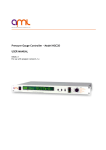
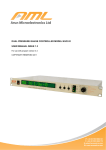
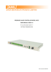
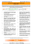
TITANIUM SUBLIMATION PUMP CONTROLLER MODEL TSP2 USER MANUAL ISSUE 3.3 For use with instruments, serial numbers Mxx onwards. COPYRIGHT RESERVED 1996, 2001, 2010 CHECKS ON RECEIPT OF THE INSTRUMENT On receipt of the instrument check that all items on the delivery note have been received. Report any damage or shortages to the Company or the Distributor who supplied the instrument. The packing material should be retained for possible future use. FAMILIARISATION It is suggested that you familiarise yourself with the instrument and its controls before installation. SUBLIMATION PUMP CONTROLLER TSP2 SET INC. RUN FILAMENT DELAY TIME EXT. INHIBIT / TRIGGER A. 1 FAULT . Hr. DEC. SUB. TIME CONTINUOUS SUB. CURRENT DEGAS DEGAS TIME TIMED WARM SUB. Min. DEGAS CURRENT OFF ENTER 0 EXCESS CURRENT MELTS FILAMENTS. CONSULT MANUAL BEFORE SETTING. Turn the rotary switch to the fully- anticlockwise 'Off' position. Connect the mains connector to a suitable supply of the correct voltage and frequency and switch on. The display will briefly show the message: F P2.0 ( P2.0 indicates the program version number ) then: F . and the mains indicator LED should glow. The fan will not run. Turn the rotary switch to 'Filament'. The display will show the filament number in use: F1 . Press the 'INC' or 'DEC' button briefly. The filament number changes and flashes, indicating that a change of filament has been requested. Press the 'Enter' button to confirm the change and stop the flashing. If you do not confirm the change within a few seconds the filament number reverts to that previously selected and stops flashing. All of the stored parameters indicated by the 'Set' locations of the rotary switch are selected and changed in a similar way. The 3 digits at the right of the display show the numeric parameters and the column of 3 green LEDs indicate the units of the parameter. Some of the times can be set in minutes and tenths up to 59.9 minutes then in hours and tenths above. If the 'Inc' or 'Dec' buttons are held down the number changes repeatedly and at an increasing rate. The parameters 'Delay Time', 'Sub. Time' and 'Sub. Current' control the cyclic timing of sublimation in 'Timed' running of the controller. The same current is used for 'Continuous' sublimation. 'Degas Time' and Degas current' are used to select a lower current and a longer time to heat the filament and pump structure for degassing without sublimation. Stored parameters are maintained when the instrument is switched off. INSTRUMENT INSTALLATION Mounting The instrument is suitable for mounting in a standard 19" rack and occupies 2U ( 3.5", 89mm) of the rack. The mounting holes in the front panel are intended for retaining the instrument in the rack and will not support its weight. Additional support is required toward the rear and various arrangements are provided by rack manufacturers for this purpose. Ventilation The instrument is ventilated by a thermostatically-controlled fan mounted on the rear panel and through grilles on the top of the case. The grilles must not be obstructed and a free-flowing supply of cooling air must be available. The instrument is tolerant of operation at elevated ambient temperatures up to 30 Celsius, although long-term reliability will be enhanced by operation at the lowest possible temperature. If there are other instruments in the rack which generate significant amounts of waste heat, try to ensure that this is deflected away from this instrument. Connection to the mains supply The mains is connected via an IEC CEE22 pattern connector. The range of nominal supply voltages for which the instrument will operate correctly is shown on the rear panel. Consult AML if these do not match your supply voltage. Do not use isolating transformers or auto transformers for matching to another supply voltage as this will disturb the operation of the regulation and protection of the instrument. The instrument is normally set for operation on 50Hz supplies: consult AML if your supply is 60Hz. Earthing ( Grounding ) SAFETY WARNING THE INSTRUMENT MUST ALSO BE CONNECTED TO EARTH (GROUND) BY THE STUD PROVIDED. DO NOT REMOVE THE LOCKNUT FIXING THIS STUD TO THE PANEL. FAILURE TO PROVIDE AN EARTH CONNECTION MAY RESULT IN A SHOCK HAZARD FOR THE OPERATOR IF EXTERNAL SOURCES OF HIGH VOLTAGES ARE INADVERTENTLY CONNECTED TO THE OTHER LEADS WHEN THE MAINS LEAD IS DISCONNECTED. MIS-CONNECTIONS AND FLASHOVERS ARE COMMON IN VACUUM SYSTEMS. Fusing The rating of the mains fuse is printed on the rear panel next to the fuseholder. It must be replaced with a glass 20mm x 5mm anti-surge fuse (identified with a "T" next to the current rating) of the same type and rating. Fuses used must comply with IEC 127, part 2, sheet III. There is provision to house a spare fuse in the fuse drawer, which is integral to the mains connector. The inner fuse in the drawer is the one connected to the circuit. It is necessary to disconnect the mains supply when replacing fuses. Connection to a pump with a TSP2L6 cable Do not shorten the pump cables, as this will cause the instrument to reject a good pump filament as a short circuit. Longer cables of adequate cross-section can be used: consult the next section. If your pump cartridge has 3 filaments it is suggested that the red wire, marked 4, is withdrawn. Switch off and remove the mains cable. Remove the lid. Introduce the pump cable through the gland at the right hand side of the rear panel. Identify the pump terminals. Make connections only to these terminals. Connect the ring terminals on the wires in the pump cable to the similarly numbered studs and them with the M5 nuts and shakeproof washers contained in the accessory kit. The black wire is connected to Fcom. fix Do not remove the nuts already connected to these studs. These wires carry up to 55A RMS, so tight connections are necessary. Failure to make a connection may result in power dissipations of of watts in the stud and may damage the printed circuit board and nearby components. A torque Newton-metres is satisfactory. Ensure that there are no short-circuits to other components or studs and check for loose debris, or washers inside the case. good tens of 4 nuts Replace the lid. Install and connect the pump according to the manufacturer's recommendations. TSP2 is suitable for cartridges having up to four straight, zig-zag or hairpin filaments between 1.8 and 2.1 mm nominal diameter. Alternative cables The resistance of the cable should be in the range of 40 to 50 milliohms at 20C. This is the sum of the resistance of one of the filament wires and the common return wire. Cables of lower resistance may cause the instrument to reject good pump filaments as short-circuits. Cables of significantly higher resistance may reduce the maximum current available. The cable and conduit should have a current rating of 55A RMS at the highest expected ambient temperature. Wires should be terminated at the instrument end with substantial copper ring terminals suitable for M5 studs. AML 6 metre cable have 6mm 2 wires, 10 to 12 metre cables will require 10mm2 wires. It may be more economical to construct long cables with a common wire which has a significantly larger cross-section than the others. OPERATION FAILURE TO READ AND FOLLOW THESE INSTRUCTIONS MAY RESULT IN FILAMENTS BEING MELTED. Degas It is assumed that the pump cartridge is installed and under vacuum below 1 x 10 -5 millibar and that adequate means to measure pressure are available. New pump filaments and those which have been exposed to air since they were last used must be degassed. This process must be done with care to avoid excess gas load on the system and to ensure that all filaments in the cartridge are adequately degassed. The following suggested procedure will ensure that this is done safely. Set the degas current to 25.0A initially and the degas time to 30 minutes. This current will ensure that the filaments will become hot enough for adequate degassing without sublimation Switch to 'degas' and observe the filaments, if possible. While the current is being increased the 'WARM' LED flashes and the set current on the display increases by 1 amp every 6 seconds. As the filament warms the pressure in the system will increase. The thermostatically-controlled fan may begin to run during or after degas. If the system pressure approaches a level which is hazardous for the pumps or gauges note the pump current and turn the rotary switch to the 'EXT' or 'OFF' positions. The pressure burst should subside as the filament cools. Set the degas current to an amp or two less than the current at which the pressure became hazardous and restart degas. The pressure burst should subside within a few minutes and another attempt can be made to degas at 25A. When the indicated degas current has reached 25A observe the pressure from time to time. It will probably start to decrease and stabilise, indicating that the filament surface is substantially gas-free. Repeat the degassing process for the remaining filaments. Since the structure has been heated by the degassing of the first filament less gas will be evolved and less close observation of the pressure will be necessary. Experienced users prefer a more efficient procedure which heats each filament in turn for short periods with an increasing current. The 'Degas' function may be used to keep the structure hot as the system cools at the end of a bake. Deriving the Sublimation Current It is assumed that the pump cartridge has been degassed and is in an ion-pumped system under vacuum of 1 x 10⁻⁵ to 1 x 10⁻⁷ millibar and that adequate means to measure pressure are available. Because of the slight modulation in filament temperature caused by the integral-cycle switching control of filament current, it will be necessary to set a significantly lower current than with supplies using other control techniques. The exact current required depends on the design of the cartridge and its installation and must be found by experiment. For 2.1mm filaments it will normally be between 32 and 35A. The difference between the current required for sublimation and that which will melt the filament can be less than 1A. The current is regulated and is not affected by mains voltage changes or by the cables warming up. There is a 'soft switching' feature to avoid thermal shocks to the filament. The current is increased from zero at 2A per second, held at the set current for the sublimation period and then decreased at 4A per second. During the warming and cooling the 'WARM' LED flashes and when the set current is achieved the 'SUB' LED glows steadily. The current is shown on the display, but is replaced momentarily at intervals by the elapsed time when the set current has been achieved, to indicate the progress of sublimation. During the controlled cooling period all control functions are inhibited until the current has reduced to zero. Ensure that shutters fitted to viewport windows are closed. Set the sublimation current to 30.0A initially, a sublimation period of 0.5 minutes and a delay period of 1 minute. Select 'Timed' on the rotary switch and wait 1 minute while the delay period elapses. When the filament current starts to rise observe the pressure in the system and be ready to switch to 'EXT' or 'OFF' if it approaches a level hazardous to the pumps or gauges. The pressure will rise steadily and should stabilise at a safe level a few seconds after the 'SUB' LED illuminates. If it is found necessary to switch off the current because of an excess gas load then follow the degassing procedure described in the previous section, then restart this procedure. If the 'FAULT' LED illuminates consult the section on display messages. The thermostatically-controlled fan may begin to run during or after sublimation. Increase the sublimation current to 31A. Wait a few minutes and repeat the timed sublimation. If sublimation occurs then a rapid reduction in pressure will occur either during the time when the 'SUB' LED is illuminated or slightly thereafter. This indicates that sublimation has occurred. If sublimation has not occurred increase the current in steps of 1A and try again successively at currents up to 35A. Wait several minutes between each attempt. As soon as sublimation is detected by the pumping effect, record the current setting and allow the pump to cool and the pressure to stabilise. If no evidence of sublimation pumping is seen at a current of 35A increase the set currents by smaller increments of 0.2A and allow a few minutes between each attempt for the cartridge to cool, as this will reduce the risk of melting a filament. Once sublimation has occurred there will be a period during which there will be a supply of getter material available. At pressures above 1 x 10⁻⁶ millibars this will be exhausted in a few seconds at 1 x 10 -7 millibars it will last a few minutes, at UHV it will last for tens of hours. Do not sublimate again until the supply of getter material is exhausted and the pressure begins to increase. If a leak valve is present on the system this can be used to increase the frequency at which sublimations can be performed for experiment. The sublimation current derived by the procedure above may be inadequate to provide sufficient getter material for sustained pumping. This may be increased by increasing the sublimation time ( to say one or two minutes ) or by increasing the current in steps of 0.1A. The control achievable by modifying the sublimation time is much finer than by modifying the current. If increasing the sublimation does not decrease the ultimate pressure then check for leaks. Sublimation It is assumed that the procedure to derive the sublimation current has been performed. Sublimation times of between 0.5 and 2 minutes are normal. The thermostatically-controlled fan may begin to run during or after sublimation. The usual manual method of controlling the pump is to set a delay time in accordance with the pressure within the system and to select 'TIMED' on the rotary switch. This causes a sublimation to be performed immediately followed by subsequent sublimations at the selected interval. Suggested delay times are as follow:pressure exponent mBar -7 -8 -9 -10 or below delay time 10 min 30 min 90 min 10 hours Further fine adjustment of the control of sublimation can be done when the system is close to its base pressure. The sublimation time should be progressively reduced after each sublimation to find the setting at which the pressure is just beginning to rise at the end of the delay time The use of this setting ensures that only sufficient material to form a layer of getter material a few molecules thick is sublimated, which will extend the life of the filaments. Continuous sublimation is only useful at pressures in the range 10-5 to 1 x 10⁻⁶ millibars. In normal systems this range will be traversed in a few minutes. Use of the inhibit and trigger function. A connection between pins 1 and 2 of the 'External' connector on the rear panel will prevent the instrument from providing output current. If the rotary switch is moved to any of the 'Run' positions the display shows: Fx Inh If the rotary switch is left in the 'Ext' position then a single timed sublimation will be triggered whenever the connection between pins 1 and 2 is momentarily removed. This forms a simple means of external control of sublimation from, for example, a NGC2 Pressure gauge controller. A further sublimation may not be triggered until the present sublimation, including the controlled cooling period, has finished. Do not connect any source of voltage or current to the 'External' connector. DISPLAY MESSAGES All detected fault conditions will result in the 'Fault' LED flashing. Fx oc. indicates that filament x is open-circuit, incorrectly wired or does not exist. Fx SC. indicates that filament x is short-circuit, either to chamber earth (ground) or to another filament. There may be a problem with the cable connection to the studs inside the case. If there is no obvious short-circuit then the cartridge resistance is unusually low, probably because it has a new filament which has not been degassed. Degassing the filaments will normally rectify the problem. Fx Hot This should only occur after continuous operation for long periods at high current in a high ambient temperature. Normal operation will be restored as soon as the temperature falls within the working range. Do not short out the thermostat or otherwise override this fault. If this fault message is displayed during normal (low duty-cycle ) operation check whether the fan is running when the heatsink temperature is over 40C. Fx Inh This message is not a fault and the 'Fault' LED does not flash. It indicates that there is an inhibit signal present on the 'External' connector and that sublimation or degas has been inhibited. APPENDIX A Tests and measurements on the TSP2 All known TSP pump cartridges have the filament common terminal connected to the vacuum chamber earth (ground). To avoid return currents flowing in the mains earth the output circuits of the TSP2 are connected to the instrument earth (ground) via a 100 ohm resistor. Connection of any other earth to these circuits will affect the output current regulation and may result in large currents through the additional earth connection. The TSP2 is capable of producing peak currents of 200A in an oscilloscope probe earth lead. DO NOT CONNECT TEST EQUIPMENT WITH EARTHED (GROUNDED) INPUT TERMINALS TO A TSP2 WITH A PUMP CARTRIDGE OR OTHER EARTHED LOAD. The output voltage and current of a TSP2 are full-wave rectified, mains-frequency sinusoidal waveforms with some whole cycles missing, to achieve regulation. They can only be measured with accuracy by using a true RMSresponding meter which has direct coupling and a single low-pass filter time-constant of >4 seconds, or equivalent. Most RMS meters are AC-coupled and respond only to the alternating component of the output, giving incorrect results. Reasonably accurate measurements with less than 5% error can be made by using a 4-second, low-pass filter and a DC voltmeter. The readings obtained by this method must be multiplied by 1.1 to convert the average measurement to RMS. For measuring output currents a good-quality 4-terminal shunt is essential. A convenient test load may be made from a 20 to 25 metre length of 10mm 2 copper cable. The cable must be adequately cooled and must not be used when wound on a drum or reel. The absolute maximum output duty-cycle in degas mode is limited to 25%. This is because the cycle-by-cycle current limit in this mode of operation is different than in timed or continuous mode. This is necessary because new filaments have different characteristics until their crystalline structure permanently changes at dull-red heat. For this reason it may not be possible for the instrument to supply 25A degas current into all loads under minimum supply voltage conditions. This is of no practical consequence. THERE ARE NO USER ADJUSTMENTS OR LINKS INSIDE THE INSTRUMENT. ASSISTANCE In the first instance contact the distributor or supplier of the equipment. Always quote the serial number of the instrument and the version number of the program. Do not return products to AML without prior approval. Arun Microelectronics Ltd Fitzalan Road Arundel West Sussex BN18 9JS England Tel. +44 (0)1903 884141 email. [email protected] www.arunmicro.com