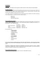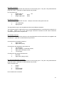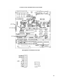
1
ARUN MICROELECTRONICS LTD.
PRESSURE GAUGE CONTROLLER MODELS PGC3 and PGC3T.
USER MANUAL ISSUE 1.3
AML Part Number SPGC3MANUSR
For use with Program Version 1.06 onward.
COPYRIGHT RESERVED 1991, 1994
The information contained in this manual has been carefully checked and is believed to be correct. No
responsibility is assumed for any errors. User comment and criticism is welcome: please write quoting
the serial number of the instrument and the version number of the software as displayed by the
instrument to:
Customer Services,
Arun Microelectronics Ltd.,
Fitzalan Road,
ARUNDEL,
West Sussex. BN18 9JP
England.
Please direct other enquiries to the distributor or agent from whom you purchased the instrument.
CONTENTS
1. INTRODUCTION
2. INSTALLATION
2:1 Checks on receipt of the instrument.
2:2 Ion gaugehead installation.
2:3 Instrument installation.
2:3.1 Mounting.
2:3.2 Ventilation.
2:3.3 Connection to the mains supply and earthing.
2:4 Fusing.
2:5 Ion Gauge Cables.
2:5.1 The ion gauge power cable.
2:5.2 The ion gauge collector cable.
3. OPERATION
3:1 Familiarisation
3:1.1 Switching On, basic display functions
3:1.2 Password protection
3:1.3 Preparing to measure pressure. Setting the Ion Gauge parameters.
3:2 Pressure Measurement.
3:2.1 Pressure measurement using Pirani/TC Gauges.
3:2.2 Calibration of Thermocouple Gauges.
3:2.3 Starting the Ion Gauge.
3:2.4 Problems with starting or running the Ion Gauge.
3:2.5 Measuring pressure with the ion gauge.
3:3 Emission current selection.
3:4 Operation of the ion gauge at high pressures
3:5 Process Control and Trips
3:5.1 Use and wiring of the relays
3:5.2 Assigning the relays to gauges
3:5.3 Setting trip pressures
3:6 Leak Detection.
3:7 Resistive Degas.
3:7.1 Running degas.
3:7.2 Problems in degas.
3:8 Capacitance Manometer
3:9 Recorder Output.
2
CONTENTS
3:10 External inhibit of the Ion Gauge.
3:11 Remote operation
4. FAULT MESSAGES
APPENDIX A
Gauge principles.
A.1 Ionisation gauges.
A.2 Pirani/TC Gauges
A.3 Capacitance Manometers.
APPENDIX B
Connectors.
B.1 Mains connector.
B.2 Ion gauge power connector.
B.3 Ion gauge collector connector.
B.4 Pirani connectors.
B.5 Remote connector.
B.6 Auxiliary connector.
B.7 Thermocouple gauge connectors.
APPENDIX C
Host Computer Serial Interface.
RS232 output data format.
APPENDIX D
Functions and locations of the internal links.
3
1. INTRODUCTION
This Pressure Gauge Controller is designed to replace earlier generation equipment and provides
enhanced performance and facilities at significantly reduced size and with no increase in cost. The large
easily-read LED display allows viewing of pressure in either bargraph or numeric formats, selectable
with a single key. A voltage analog of ion gauge pressure is available. Four mains-power-rated
changeover relays, flexibly assignable to gauges by means of internal links, are provided. Pressure
setpoints for the relays are maintained in the absence of mains power.
Ease of Use
The instrument is controlled by a single rotary switch, the functions of which are clearly marked. The
indication of pressure and trip pressure settings are controlled by three keyswitches.
High Accuracy
The two most significant factors which determine the performance of ion gauge controllers are the
accuracy of emission control and the quality of the electrometer measuring the collector current. This
unit offers improvements in both of these critical areas.
Precise Emission Control
The filament power is provided by a smooth, direct current supply controlled by a fast-acting control
circuit instead of the normal transformed and chopped mains supply. This allows control of emission
current to an accuracy of about 1%, besides eliminating a source of potential electromagnetic
interference.
Advanced Electrometer Design
An electrometer with a logarithmic characteristic is included as this gives a wide dynamic range which is
guaranteed to be monotonic and smooth over the entire range of the ion gauge. A novel compensation
technique ensures that the error currents in the logging circuits do not cause an optimistically low
pressure reading to be given at the bottom of the operating range, as is common in log electrometers.
The settling time at low input currents is minimised by a new non-linear frequency compensation
technique. Conformance and high ambient temperature performance are improved by advanced
temperature compensation techniques. The electrometer is mounted directly in the path of incoming
forced air and is thermally isolated from internal sources of heat.
4
2. INSTALLATION
2:1 Checks on receipt of the instrument.
On receipt of the instrument remove all packing material and check that all items on the shipping list
have been received. Report any damage or shortages to the Company or the Agent who supplied the
instrument. The packing material has been specially designed to protect the instrument and should be
retained for possible future use.
2:2 Ion gaugehead installation.
Consult the information supplied with the gaugehead for advice on flanges, gaskets and adaptors for
mechanical fixing. Consult section 2:5 and Appendix B for more information on making or adapting
cables to connect between the gaugehead and instrument.
Mount the gaugehead in a position where the free electrons generated in its vicinity will not affect other
equipment. The performance of the ion gauge may be affected by other electron or ion generating
processes within the vacuum chamber: should shielding of the gaugehead be necessary, ensure that
the conductance between the gaugehead and volume of interest is not significantly decreased by its
presence. The orientation of the gaugehead should be such that the filament is to the side of, or below,
the grid structure. This will ensure that if the filament should sag or break it will not short-circuit to the
grid.
The gauge and controller are protected from all normal failure modes. Users should be aware of
potential hazards from other equipment, however, particularly those introducing high voltages into the
vacuum chamber (X-ray sources for example). As a direct discharge from one of these at high
pressure may cause extensive damage, shielding should always be introduced in such cases.
2:3 Instrument installation.
2:3.1 Mounting.
The instrument is suitable for mounting in a standard 19" rack and occupies 1U (1.75" , 44.5mm) of the
rack. The mounting holes in the front panel are intended for retaining the instrument in the rack and will
not support its weight. Additional support is required toward the rear and various arrangements are
provided by rack manufacturers for this purpose. Support brackets may be mounted on the tapped M3
fixing holes on the sides near the rear. If these or other arrangements are attached to these holes,
ensure that the screws used are steel and penetrate the case between 6 and 10 millimetres.
2:3.2 Ventilation.
The instrument is forced-air ventilated through grilles on the right side and a vent in the rear panel.
Mount it in a location where there is an adequate supply of air as close as possible to cool room-ambient
temperature. The instrument is tolerant of, and is compensated for, operation at elevated ambient
temperatures up to 45 Celsius. Long-term accuracy and reliability will be enhanced by operation at the
lowest possible temperature. If there are other instruments in the rack which generate significant
amounts of waste heat, try to ensure that this is deflected away from this instrument.
5
2:3.3 Connection to the mains supply and earthing.
The mains is connected via an IEC CE22 pattern connector.
THE INSTRUMENT MUST ALSO BE CONNECTED TO EARTH BY THE STUD PROVIDED.
FAILURE TO PROVIDE THIS CONNECTION MAY RESULT IN A SHOCK HAZARD FOR THE
OPERATOR IF HIGH VOLTAGES ARE CONNECTED TO THE GAUGE OR SIGNAL LEADS WHEN
THE MAINS LEAD IS DISCONNECTED.
The mains supply is filtered to help prevent conducted electromagnetic interference affecting the
operation of this or other equipment nearby. To ensure that this filtering is effective, and because there
is an earth leakage current generated within the instrument, it is necessary to return this directly to the
vacuum system ground reference star point. Ensure that other instruments are directly and separately
earthed so that return or fault currents cannot flow in any common ground impedance. This is
particularly important in cases where there are high voltage power supplies in the system. In such cases
there must be specific low impedance paths for return or flashover currents: reliance on frame continuity
or sneak paths will cause noises and spikes to be coupled into instrumentation. Low resistance
connections do not necessarily have low impedance, which is most successfully achieved with a Litz
conductor of large cross-section and number of strands.
Information on wiring for process control will be found in section 3:5, below.
2:4 Fusing.
Two fuses for instrument protection are provided. Do not use fuses of other types or ratings, as this may
result in damage to the instrument or gaugeheads under fault conditions.
The rating of the mains fuse is dependent on the range of supply voltages from which the instrument is
to be operated, and is printed on the rear panel adjacent to the fuseholder. It must be replaced with a
20mm x 5mm glass anti-surge fuse of the type and rating. Such fuses are marked with a "T" after the
current rating: ceramic types are not suitable. Spare fuses are provided in the accessory kit. There is
provision to house a spare fuse in the fuse drawer, which is integral to the mains connector. It is
necessary to disconnect the mains supply when replacing fuses.
6
2:5 Ion Gauge Cables.
The use of correctly constructed cables will enable the instrument to meet its specification. The
following is a general guide to the considerations affecting ion gauge cable construction: a specification
of connector types and pin connections is given in Appendix B.
2:5.1 The ion gauge power cable.
Caburn-MDC supply cables type CLIG1 for use with this controller and MDC type BATT and BAIR
gaugeheads. The use of this cable is recommended.
The ion gauge power cable must be made with conductors of cross section adequate to carry the normal
filament and degas currents or the worst-case fault currents at the highest ambient temperature
expected. The cross sectional area of all the wiring should be a minimum 1 square millimetre and
preferably more. The insulation on all wiring should be rated for at least 500 volts RMS and should be
adequately protected against mechanical damage.
For the filament current (pins 4, 5 and 6) the wiring should be rated at 6A or more. The degas grid
current can be 17 A and the wiring on pins 10 and 12 must be capable of carrying this current: types BK
32/0.2 and BK 30/0.25 are suitable.
A further consideration is the voltage drop in the cable at maximum current. It is good practice to
minimise the drop in the cables by making them as short and of as large a cross section as is
convenient, as this minimises the temperature rise in the instrument. Long cables of inadequate crosssection may cause the instrument to be unable to support emission or supply adequate degas power,
and error messages reporting spurious gauge failures may result. AML will be pleased to advise on the
subject of long cables.
2:5.2 The ion gauge collector cable.
The ion gauge collector cable should also be as short as convenient. The centre pin of the BNC
connector must be gold plated. Although this cable is screened, the amount of interference which can
be induced is proportional to its length and can become significant at extreme UHV. Site the cable run
away from other cables carrying high power or high frequency signals. The cable installation should be
such that movement or flexing is discouraged. Mechanical movement of the cable can generate
triboelectric charges which may affect UHV measurements.
It is important to avoid the production of "earth loops" in sensitive signal return paths as these can have
significant currents induced in them at mains frequency. The screen of the collector cable should ONLY
be earthed at the instrument end. If existing cables are to be adapted, and are currently connected to
earth at the gauge end, disconnect the screen but ensure that the guard cylinder around the collector
feedthrough on the ceramic gauge base remains connected to the chamber earth. This is important, as
it provides a path to earth for leakage on the surfaces of the ceramic from the grid voltage which would
otherwise add to the collector current.
7
3. OPERATION
3:1 Familiarisation
Operation of the instrument is designed to be easy for users familiar with vacuum system operation and
with the types of gauges used. Brief descriptions of the principles of operation of various types of gauge
will be found in appendix A.
3:1.1 Switching on, basic display functions.
Connect the instrument to the mains supply. Do not connect any gauges or other equipment to the
connectors on the rear panel at this stage. Rotate the emission switch to the "OFF" position. Switch on.
The green LED indicator adjacent to the mains switch will illuminate and the fan will start and the main
LED display will show sequentially
"PGC3"
then
"V X.YY"
(X.YY is the version number of the embedded software.)
then
"P1 ATM"
with a pair of dots on the left end indicating the units of pressure measurement. Further dots at the right
end of this display may be illuminated, showing that one or more of the relays is energised. The
"Pirani/TC" LED display will show two horizontal bars.
3:1.2 Password protection
Access to the process control trip settings is controlled by a 3 digit password number. DECIDE WHAT
YOUR NUMBER IS TO BE AND RECORD IT! To set the password press the TRIPS switch. The main
display will show "PW ???". Using the INC and DEC switches set the number you have decided and
press TRIPS again. Press TRIPS a further four times to cycle through the trip displays: these are
described fully in section 3:5, below, but understanding them is not required at this stage.
3:1.3 Preparing to measure pressure. Setting the Ion Gauge parameters.
Disconnect the power connector and remove the smaller screws at the sides of the instrument. Note
that the ventilation slots are at the right side, when viewed from the front. Remove the cover in an
upward direction and locate LK2 at the rear of the right hand circuit board, near the filament switch.
Spare links are stored on LKPARK which is on the left edge of the same circuit board. Fit or remove
links on LK2 according to the following:
Specifying the Pirani/TC Interlock.
Locate LK3, adjacent to the LKPARK. Fit a link in the "PLOCK" position to prevent starting the ion
gauge when Pirani/TC 1 pressure is above 1.0E-2 millibar.
8
Specifying the units of pressure measurement.
Fit links to LK3 according to the following;
Pascal
Millibar
Torr
fit no link to U0 or U1
fit link U0 only
fit link U1 only
Before replacing the cover you may wish to adjust the links which specify other functions: a tabular
review of all links on LK3 and a diagram of their location is shown in Appendix D.
Ensure that there are no loose links or foreign material inside the instrument. Replace the cover with the
ventilation slots at the right hand side and replace the screws. Do not use screws longer than those
supplied.
Adjusting the ion gauge filament current limit and sensitivity.
If the gaugehead manufacturer has a recommended limit adjust to a little below that limit. In the
absence of a recommendation select about 1.5 Amps for Iridium and 3.0 Amps for Tungsten. This will
probably be too low for most gauges under all conditions but will protect the filaments.
Switch on with the emission switch in the "OFF" position and wait for the signing on messages to finish.
Press a "Change Display" switch until "LIM Y.Z" is displayed. Y.Z is the current limit in amperes. Use an
instrument screwdriver with a 3mm blade, and insert this in the hole on the front panel marked "LIM".
Using no more pressure than is necessary to keep the screwdriver in the slot, turn the single-turn
adjustment until the desired limit is displayed.
Press a "Change Display" switch until "S = ZZZ" is displayed. ZZZ is the ion gauge sensitivity expressed
as the reciprocal of the specified units of pressure measurement, for example per millibar. Adjust to the
value appropriate to the gauge with a screwdriver inserted through the hole marked "SENS". The
correct setting for MDC Vacuum Products Corporation's gaugeheads type BAIR and BATT is 10/Torr (=
7.5/mBar = 0.075/Pa).
3:2 Pressure Measurement.
3:2.1 Pressure measurement using Pirani/TC Gauges.
The instrument is supplied for operation of EITHER AML Pirani gauges type PVU and PVB OR MDC
Thermocouple gauges types TGT2A and TGT2AM, as defined by the absence or presence of suffix T in
the model number marked on the rear panel, respectively. Use of the incorrect gauge type or
gaugeheads of other manufacture may result in damage to the instrument or gaugehead. AML Pirani
gauges have internal adjustments and are supplied pre-calibrated, in distinction to thermocouple gauges
which require the controller to provide this facility. Calibration of thermocouple gauges before use is
essential and is described in section 3:2.2.
Switch off, disconnect the mains power lead and connect the gauges. Ensure that the lead of the
Pirani/TC gauge which is interlocked to the ion gauge is connected to the Pirani/TC 1 connector on the
rear panel.
Reconnect the power lead, and switch on. Pirani/TC gauges and capacitance manometer are powered
up immediately. The left section of the LED display shows a low-resolution histogram of Pirani/TC
pressure at all times. This should be read against the scale at the top or bottom as indicated by the line
to the illuminated pressure unit indicator LEDs at the left end of the main section of the LED display.
9
Pressing the "CHANGE DISPLAY" switches will change the format of the display and the source of the
measurement sequentially. P1 and P2 are Pirani gauges, T1 and T2 are thermocouple gauges and C is
the capacitance manometer. The numeric indications of Pirani/TC pressure allow a higher resolution
measurement of these pressures to be made.
If "P1 OC" or "P2 OC" is displayed the sensing filament is open circuit.
Pirani/TC gauges are not very accurate or repeatable transducers at pressures close to atmospheric.
For this reason, the instrument has no discrimination of pressures between 1 bar and 5 mbar. This is of
no practical consequence, since a typical rotary-pump roughed system will traverse this range in a few
seconds and will adequately indicate that pumpdown is progressing by making the characteristic noises.
Badly-calibrated or oil-contaminated Pirani/TC gaugeheads may even indicate 5 mbar or less at
atmospheric pressure! Accurate pressure readings in this range are achieved by capacitance
manometers.
3:2.2 Calibration of Thermocouple Gauges.
PGC2T includes a multi-turn potentiometer adjacent to each thermocouple gauge connector on the rear
panel. This is used to adjust the TC heater current and for safety this is adjusted to minimum (fully
counter-clockwise) before despatch. Calibration before use is essential. Connect the gauge to the PGC
and expose it to atmospheric pressure and ensure that the instrument indicates "ATM" without
adjustment. Pump the gauge to a pressure below 10-3 millibar or torr. Adjust the potentiometer until a
reading of 1E-3 is obtained. Do not adjust the potentiometer any further in the clockwise direction as this
may damage the gaugehead.
3:2.3 Starting the Ion Gauge.
Before starting the ion gauge you should have specified the filament type, and set the filament current
limit as described in section 3:1.3, above. Select the filament in use by means of the toggle switch on
the rear panel. Gauges type BAIR have only a single filament and if these are used with a CLIG1 lead
which has been correctly installed will operate if "Filament 1" is selected.
Start pumping the system. When the system pressure is low enough, attempt to start ion gauge
emission. The Pirani/TC interlock will prevent this if Pirani/TC 1 pressure indication is above 1x10E-2
millibar.
Emission should be initiated at 100μA. Rotate the switch to the 100μA position and observe the LED
display. While the gauge filament is heating the display shows the selected emission current. After
about five seconds a display of pressure in numerical format should be shown.
There may be a pressure burst after the gauge is started, due to evolution of gas from the hot filament.
However, if the system pressure is very low and if the gauge has been previously outgassed the initial
display may indicate a very low pressure which may take some tens of seconds to settle to a
representative reading.
If any display other than a reasonable display of pressure is obtained after about 30 seconds refer to
section 3:2.4 for an explanation.
When the pressure display stabilises switch emission off and select the other filament (if there is one).
Operate the second filament at 100μA for a minute or two. This will equalise the stress in the filaments.
Increase the emission current to 1mA and then to 10mA after the pressure reading is stable again. It will
be necessary to increase the "LIM" adjustment to achieve emission at higher currents if "IG UEM" is
displayed.
10
When you have achieved 10mA emission you should then turn the "LIM" adjustment slowly
anti-clockwise just until underemission is reported. View and record the current limit and then increase it
slightly to give a margin of safety. If the ion gauge or filament is changed the adjustment will need to be
repeated. It is worthwhile taking the trouble to find the optimum setting of this control, as this will
improve the protection and longevity of the filament.
3:2.4 Problems with starting or running the Ion Gauge.
If "IG UEM" (underemission) is reported at startup or on increasing emission this is probably due to the
filament current limit being set too low. However, if the grid is not connected or shorted to ground the
same message will be given. Prudent operators will check the cables before increasing the allowed
filament current. Disconnect the mains power connector before checking any cables. The filament
current limit adjustment can be made at any time but it is advisable only to do so when the ion gauge is
off and the limit is being displayed.
If "IG OEM" (overemission) is shown there is probably a short circuit from grid to filament. Disconnect
the mains power connector before checking cables.
If "FIL OC" (IG filament open circuit) is shown the cable or filament is probably open circuit. The same
message is shown if the gauge connector is not properly mated, or a non-existent filament is selected.
Disconnect the mains power connector before checking any cables. In some cases if there is a
high resistance connection, or the cable is long, or of inadequate cross section this fault may be reported
after some period of normal operation. Refer to section 2:5.1 regarding cables. To change to the other
filament use the switch on the rear panel. Run the new filament at low emission to degas it.
If "PLOCK" or "TLOCK" is reported the Pirani/TC interlock is preventing emission since Pirani/TC 1
pressure indication is above 1x10E-2 millibar. Pirani/TC gauges are generally more repeatable at the
lower end of their pressure range, although not necessarily more accurate. AML Pirani gauges are
shipped calibrated but there is an adjustment for the low pressure end of the scale, and this may need
attention. Alternatively, if you are confident that the system pressure is low enough and the Pirani/TC
interlock is preventing the ion gauge from being run, then remove the interlock link, as described in
section 3:1.3.
If "EXT" is reported then emission is being prevented by an external inhibit signal on the Auxiliary
Connector.
If the emission LED is extinguished and the main LED display subsequently shows "PGC3" followed by
a software version number then the instrument has detected a short-circuit on the filament.
3:2.5 Measuring pressure with the ion gauge.
It is assumed that you have followed the procedure in section 3:2.3 and are running the ion gauge at
100μA emission current.
Review the formats of pressure display available by pressing the "DISP" switch during emission the
Pirani/TC pressure is indicated in the separate dedicated section of the LED display. The status of the
four relays is shown at the right end of the main LED display. Four pairs of dots represent the status of
the four relays. When illuminated these represent the energised condition. While ion gauge pressure is
displayed in numeric format an arrow showing the current trend in measured pressure is shown at the
right of the display.
Two styles of histogram (bargraph) display are available, the long histogram shows most of the range of
ion gauge pressures and the short histogram shows a single decade. The pressure trend is indicated by
11
a pointer superimposed at the right end of the bar.
The long histogram is interpreted against a row of dots adjacent to scale marks on the panel which
indicate the exponent. The mantissa is interpolated between adjacent scale mark dots. Although the
resolution is only four points per decade this display is useful during pumpdown. At pressures below 1E10 millibar the long histogram display is not available and is replaced by the numeric display.
The diagram below represents a short histogram of pressure at 2E-9 millibar.
Note that the scale marks at the bottom of the display represent a mantissa from 1 to 10, with the double
marks on 1, 5 and 10. For Pascal the scale is at the top. Note the downward trend indication and that
relays A and C are energised. When the pressure reaches the end of the scale the instrument
automatically changes to the next scale.
The entire display can be replaced by a display of the gauge assignment and trip pressures of the
relays, by pressing the "Trip" switch. More information on this is contained in section 3:5.2, below.
Pressing the "Trip" switch a further four times will restore the former display.
3:3 Emission current selection.
You may select 100μA, 1mA or 10mA of emission current in the ion gauge, as the gauge is being
operated. For the majority of measurements emission of 1mA will be used. Although most gauges are
substantially linear and the instrument regulates emission current well, maintaining 1mA emission
wherever possible will eliminate some error in the readings.
This instrument contains an advanced electrometer circuit which is well compensated for environmental
changes. It is located directly in the path of a cooling airflow just where this enters the instrument, and it
is thermally isolated from sources of heat.
Operation of the instrument in conditions of high humidity may affect extreme low pressure
measurements if condensation is allowed to form within the case. The most common cause of this is
introducing a cold instrument into warm conditions. If this situation exists it will normally be
self-correcting after a few hours of operation in non-condensing conditions.
3:4 Operation of the ion gauge at high pressures
For operation at the upper end of the ion gauge pressure range, an emission current of 100μA is
available. This may be used as a means of extending the upper pressure limit of operation with tungsten
filaments as the operating temperature is considerably reduced, and oxidation (and other) reactions are
retarded. The reduction in temperature of Thoria-coated Iridium filaments is not so significant. In all
cases the recommendations of the gauge manufacturer on this matter should be followed.
12
3:5 Process Control and Trips
Four process control relays are provided, which can be used in variety of ways. The relays and their
contacts are described in the following paragraph, and their assignment and use in the remainder of this
section.
3:5.1 Use and wiring of the relays.
The contacts of the relays are shown diagrammatically on the rear panel legend, in the de-energised
condition, adjacent to the terminal blocks to which they are connected. Switching loads of more than 5
Amps is not recommended. Inductive loads, including contactor coils, should have "snubber" networks
connected in parallel to avoid arc generation which could interfere with the operation of this and other
equipment. In general, avoid introducing noise sources into the instrument via the relay contacts.
The external wiring is connected to the instrument through a two-part pluggable terminal block. This can
be removed and wired independently of the instrument. Ensure that external wiring is of adequate cross
section for the load current. Strip and twist the wires (do not tin them) and poke into the receptacle in the
terminal block. Close the leaf on the wire by tightening the screw immediately above. Take appropriate
action to strain-relieve the wiring nearby and to restrict access to the terminals if harmful
voltages are to be present. Fit the terminal block cover supplied in the accessory kit to retain the
connector and prevent debris falling into the screw heads.
3:5.2 Assigning the relays to gauges.
Each relay is assigned to a gauge and the relay is energised when the pressure is below the setpoint.
The hysteresis is fixed and the relay will de-energise when the pressure exceeds twice the setpoint
pressure. Adjustment of setpoints is described in section 3:5.3.
Relay A is assigned to the ion gauge.
Relay B is assigned to Pirani/TC 1.
Relay C and D are assigned to the ion gauge, Capacitance Manometer or Pirani/TC 2 by means of
internal links. Review their current assignments by pressing the "Trips" switch until the LEDs associated
with these relays flash. While these LEDs flash the display shows assignments of the relays C and D. If
these are not as desired they may be changed by the following procedure.
Disconnect the power connector and remove the smaller screws at the sides of the instrument. Note
that the ventilation slots are at the right side, when viewed from the front. Remove the cover in an
upward direction and locate the LKPARK and LK3 at the left hand side of the right hand circuit board.
Spare links are stored on LKPARK. Fit or remove links on LK3 according to the following:
A link in the RLC position on LK3 assigns RLC to the ion gauge.
No link in the RLC position on LK3 assigns RLC to the Capacitance Manometer.
A link in the RLD position on LK3 assigns RLD to the ion gauge.
No link in the RLD position on LK3 assigns RLD to Pirani/TC 2.
A link on the "NIGREN" position on LK3 causes the relays assigned to the ion gauge to be energised
when the ion gauge is not operating in normal emission.
Before replacing the cover you may wish to adjust the links which specify other functions: a tabular
review of all links on LK3 and a diagram of their location is shown in Appendix D.
Ensure that there are no loose links or foreign material inside the instrument. Replace the cover and
screws in the correct locations. Do not use screws longer than those supplied.
13
3:5.3 Setting trip pressures
When the instrument is running the assignment of the trips and the trip pressures can be reviewed at
any time except during degas or when a fault message is displayed.
Pressing the "Trips" switch causes the main display to show "PW ???", unless you set the correct
password number with the INC and DEC switches and confirm it with the TRIPS switch, you will not be
allowed to modify the trip pressures.
If a password has not previously been set you should do so now and RECORD THE SELECTED
NUMBER.
If a password was set and you have forgotten the number refer to Appendix D (LK4) for information on
how to reset it.
After the password is entered (or not if trips are to be reviewed without modification) the two LEDs
adjacent to "RLA" to flash. The display shows "I X-YY" , and indicates that relay A is assigned to the ion
gauge and that the trip pressure is XE-YY units.
Pressing the "Trips switch more times reveals the assignment and trip levels for the other relays in turn.
P1 and P2 are Pirani trips, T1 and T2 are thermocouple gauge trips and C is the Capacitance
Manometer trip. If relay C is not displayed then it has been assigned to the capacitance manometer
which has been specified as non-existent.
While the display is in this condition the trip levels may be adjusted by means of the "INC" and "DEC"
switches if the password was entered at the start of the sequence. Note that the terminal values
reached are "EN" and "DN" , representing the permanently energised or de-energised condition of that
relay. The new trip levels become active when all four have been reviewed and changed if desired and
the normal display is restored. If a delay of more than about 15 seconds occurs during the review
process in which no switches are pressed then the trip display "times out" and the normal display is
restored with all the trips unchanged.
The trip levels are maintained in the instrument's memory, even when the power is switched off.
Users of trips on pirani and thermocouple gauges should be aware that the resolution and repeatability
of such gauges is relatively poor and that trips set outside the range 5x10E-3 to 5mBar may exhibit
undesirable repetitive switching.
3:6 Leak Detection.
The leak detector works by indicating rapid changes of pressure on a bargraph and a
frequency-modulated tone. Such changes are produced with a probe gas or volatile blocking agent. It is
difficult to exercise this function unless you have a leak valve (or a leak!) on the system, although you
may be able to produce a pressure burst by switching on other equipment or firing a titanium sublimation
pump. During leak detection the ion gauge overpressure trip and process control relays function
normally.
Select which gauge is to be used by switching the ion gauge into emission to leak detect using the ion
gauge or switching emission off to use Pirani/TC 1. Which gauge is best to use will depend on the
pressure at which the leak is limiting pumpdown. If you select the ion gauge the interlock with Pirani/TC
1 still functions.
14
Press the "Change Display" switches until the LED display shows "LEAK" followed by a histogram of
rate of pressure deviation with baseline restoration. If you have means to simulate a leak, you should do
so and observe the effect on the display and tone. The sensitivity of the ion gauge leak detection can be
altered by changing the emission current.
A volume control for the sounder is adjacent to the emission control switch and is accessible with an
instrument screwdriver with a 3mm blade.
After a pressure change has been observed, turn off the probe gas supply or stop applying the blocking
agent and wait until the baseline restorer has caused the histogram and tone to return close to the
centre of their range. This shows that the leak detector has adjusted to the new system pressure and
does not necessarily indicate that the pressure is the same as before probe gas was introduced via the
leak. A blocking agent may give rise to a deviation first to the right and then to the left before settling. A
probe gas may give a single deviation in either direction, depending on the relative sensitivity of the ion
gauge to the residual gas in the chamber and the probe gas, and to the relative pumping rates for those
gases. Further localisation of a leak may be attempted after the deviation has been restored.
3:7 Resistive Degas.
Ion gauges designed for resistive degas have a helical filament made of resistive material. In order to
degas the filament a current is passed through the filament to raise it to red heat. The PGC3 is designed
to supply between 35 and 40 watts to a typical gauge for a period of 30 seconds. Extended or repetitive
degassing of these gauges over a short period is not recommended by the manufacturers, as melting of
the grid could occur. The PGC3 prevents this by allowing a maximum duty-cycle on degas of 25%.
Degas is only allowed to start at pressures below 1 x 10⁻⁵ millibars and is terminated if the pressure
exceeds 1 x 10⁻⁴ millibar. Degas is only allowed if the emission current is 10mA.
3:7.1 Running degas.
Gauges should have been run for some time at 10mA emission before pressing the "DEGAS"
pushbutton, to ensure that the filament has been adequately outgassed. Ensure that the pressure in
the system is sufficiently low, and that the pumping capacity is adequate for the expected gas load.
Observe the main instrument display as the pushbutton is operated, as any fault message will be shown
briefly.
During degas the pressure is shown on the LED display and the emission LED flashes. Degas may be
terminated by pressing the pushbutton again.
Some fault conditions which terminate degas allow emission to continue, for example "P BURST". In
these cases the error message is transient and there is no lasting indication of a problem. It is
recommended that operators observe the display during degas a few times after the ion gauge has been
exposed to air.
3:7.2 Problems in degas.
If "IG UEM" is reported during degas a grid to ground short circuit may have occurred. Attempt to run
normal emission before investigating the gaugehead or leads.
If "P HIGH" is reported, the pressure was greater than 1 x 10⁻⁵ millibar when degas was attempted.
If "P BURST" is reported, the pressure exceeded 1 x 10⁻⁴ millibar at some time during the degas period,
and degas was terminated.
15
If "IG OEM" (overemission) is reported, there was either a discharge caused by a high gas load, or a
short-circuit between grid and filament, caused by sagging or melting of the grid. First attempt to find
any short-circuit: if none is found, check that emission at 100μA, 1mA and10mA is satisfactory, after
which degas may be attempted again.
If "GRID SC" is reported there is a short circuit between the two ends of the grid, either in the gaugehead
or the connector and lead assembly. Since the cold resistance of the grid is about 0.1 ohm, which is
difficult to distinguish from a short circuit, the lead should be disconnected for investigation. This fault
message is not related to a grid to ground short circuit.
If "WAIT" is reported then sufficient time has not been allowed since a previous degas was attempted.
The maximum duty cycle allowed for degas is 25%, so after a full 30 second degas another is prevented
for 90 seconds.
3.8 Capacitance Manometer
The capacitance manometer (CM) is connected via the Auxiliary Connector. For details on this
connector refer to Appendix B.6. The instrument caters for unheated capacitance manometers with
full-scale output voltages of 10v, representing 10, 100 or 1000 millibar or Torr. 15v and -15v power is
available to drive the CM at up to 35mA, if your CM requires more power than this an external power
supply will be required: this will also allow heated CMs to be used. These have better resolution and
stability.
The CM can be interrogated by pressing a "Change Display" switch until the CM pressure reading
appears. This is only available in numeric format. If the pressure measured by the CM is greater than
its fullscale the reading displayed on the LEDs is "C > FS".
Ensure that the fullscale selected by the internal links matches that of the CM. CMs with a fullscale
defined in Torr will only give correct readings if the instrument is set up to display pressures in Torr and
CMs with a fullscale defined in millibar will only give correct readings if the instrument is set up to display
pressures in Pascal or millibar.
If pressure readings are not consistent with the measured pressure the range and units of display may
be changed by the following procedure:
Disconnect the power connector and remove the smaller screws at the sides of the instrument. Note
that the ventilation slots are at the right side, when viewed from the front. Remove the cover in an
upward direction and locate the LKPARK and LK3 at the left hand side of the right hand circuit board.
Spare links are stored on LKPARK. Fit or remove links on LK3 according to the following fullscale output
of the CM:
No CM used
10 mB/Torr
100 mB/Torr
1000 mB/Torr
fit links CM0 and CM1
fit link CM0
fit link CM1 only
fit no links
Pascal
Millibar
Torr
fit no link to U0 or U1
fit link U0 only
fit link U1 only
Before replacing the cover you may wish to adjust the links which specify other functions: a tabular
review of all links on LK3 and a diagram of their location is shown in Appendix D.
16
3:9 Recorder Output.
An analog voltage representing ion gauge pressure is available on the auxiliary connector. This is
scaled at +0.25 volts per decade of pressure and 0 volts represents 1.0x10E-12 millibar.
The output resistance of the recorder output is 1 kilohm and the output will withstand a continuous
short-circuit to either +15v, 0v or -15v, which are all present on the auxiliary connector. Consult
appendix B.6 for information on connector type and pin numbering.
The output voltage when the ion gauge is not operating is around 0v and depends on the quality of the
screening on the collector wiring.
If an analog voltage representing pressures above the ion gauge range is required, the voltage output of
the capacitance manometer is recommended. The output impedance of this is generally such that a
recorder may be driven directly.
3:10 External inhibit of the Ion Gauge.
Operation of the ion gauge may be inhibited by an external contact closure, which prevents starting of
the ion gauge by any means. The contacts should be connected to pins 7 and 8 of the Auxiliary
connector and must be isolated from any external source of voltage. Gold-plated contacts are
recommended as the internal voltage and current source are small.
3:11 Remote operation
Logging of the instrument by a host computer through the Remote connector is possible. A
demonstration program which will run on any IBM XT, AT or compatible computer with a colour VGA
monitor is available on diskette. The host computer must have at least one RS232 serial port.
Information on the interface protocols is given in Appendix C, below.
17
4 FAULT MESSAGES
All faults or potential faults detected by the instrument are announced on the LED display. Some are
accompanied by a warning sound.
UEM, OEM, FILOC, EXT, PLOCK/TLOCK, P HIGH, P BURST, GRID SC AND WAIT.
These faults are reported when attempting to start emission or degas. Refer to sections 3:2.4 or 3:7.2,
respectively.
TRIPS LOST
This fault message indicates that the trip pressures are invalid for some reason. It is present after
switch-on and is cancelled by reviewing the trips, when "PW ???" is displayed. After cancelling this fault
message switch off and on again after a few seconds. If the instrument is operating correctly the fault
should not be reported again. If this message is shown more than once after installation the probable
cause is electrical interference: refer to the discussion at the end of this section for more information.
SWITCH EM OFF
This fault message results from switching the instrument on with the emission switch in any position
other than "off". The ion gauge is prevented from operating in this condition. Normal operation is
established by rotating the emission switch to "off". This message will be present after a temporary
power failure.
LO BAT
After many years of operation the battery which maintains the trips will need replacing. Maintenance of
trip pressures when the instrument is switched off cannot be expected once this fault message has been
seen.
"P1 OC" or "P2 OC" or flashing Pirani histogram.
All of these indicate that the Pirani gauge has an open circuit sensing element.
Other erratic behaviour
Environments where there is a large amount of electrical noise may cause occasional erratic behaviour.
In extreme cases this may cause the instrument to revert to a condition corresponding to that which
pertains just after switch on, with the emission LED extinguished. This symptom shows that the
instrument's program has been disturbed in some way. Normally, the stored operating and setup
parameters will not have been altered: if they were then a warning message will be displayed.
Operation may be restored in the normal way.
18
APPENDIX A
Gauge Principles
A.1 ionisation gauges.
Ionisation gauges are thermionic triode devices. The appropriate choice for UHV use is the
Bayard-Alpert type. This consists of a very thin collector wire mounted along the axis of a cylindrical
mesh grid. The filament is outside the grid and usually parallel to it. The grid is voltage-biased positively
with respect to the filament, and the collector negatively.
A stabilised emission current is established between the incandescent filament and the grid structure.
Electrons oscillate on long paths through the open grid structure, being repelled from the central
collector and attracted to the grid. A proportion of the electrons encounter gas molecules before
reaching the grid. These molecules are ionised by the collision and are attracted to the collector to form
a current, which is proportional to the concentration of gas molecules over a very wide range.
Pressure may be derived from the ion current by solving the equation:
Pressure =
Ion current
---------------------------------------------Sensitivity x Emission Current
where the units for the two currents are the same and the sensitivity is a quoted constant for a particular
gaugehead and gas species.
The impact of electrons on the grid structure generates soft X-rays; some of these impinge on the
collector and release photo-electrons. These form a small current in the same direction as the ion
current. When this 'photocurrent' becomes significant in relation to the 'true' ion current, the gauge
ceases to function as a reliable pressure transducer and is said to have reached its 'X-Ray limit'.
A.2 Pirani/TC Gauges
The Pirani/TC Gauge is a thermal conductivity gauge. A tungsten filament in the vacuum space is
heated from a constant voltage source and is incorporated in a Wheatstone bridge. The electrical
resistance of the filament depends on its temperature and this in turn depends on the rate at which heat
is conducted away from the filament by residual gas. The thermal conductivity of a gas depends on its
pressure (below about 1 millibar) and the nature of the residual gas. The Pirani/TC gauge unbalances
the Wheatstone bridge and the voltage across the bridge represents pressure over the range of 0.5
millibar to about 1x10E-3 millibar.
The lower pressure limit is determined by the heat loss due to radiation becoming significant compared
to that due to thermal conductivity. The radiant heat loss depends on the emissivity of the filament. A
new filament is bright, but can become blackened by deposits from decomposed rotary pump oils and
the lower limit of pressure readings will rise. It is possible to clean filaments.
A.3 Capacitance Manometers.
Capacitance manometers operate by measuring the deflection of a thin circular radially tensioned
membrane between the vacuum space and a reference volume at a pressure substantially below the
operating range of the transducer. The deflection is measured as a modulation of the electrical
capacitance between the membrane and a fixed plate and converted to a voltage proportional to the
pressure difference across the membrane.
19
APPENDIX B
Connectors
IN THE SECTIONS BELOW THE MATING CONNECTORS ON THE CABLES ARE DESCRIBED.
B.1 Mains connector.
This is a female IEC CEE22 type and is supplied with the instrument in the accessory pack in the form of
a moulded lead with integral 13 Amp. British domestic-style plug. A North-American or European plug
will have been supplied if the instrument was so ordered.
If you need to change to an alternative style of connector take care to make the connections correctly to
ensure operator safety. The wires are colour-coded as follows:Brown Line
Blue Neutral
Green and yellow Earth
B.2 Ion gauge power connector.
This is supplied with the instrument in the accessory pack, in the form of a kit of parts. It is a 12 pin ITT
Cannon "Trident" rectangular male type. In the USA equivalent types are available from Burndy Inc. or
Framatone Inc., type "SMS Quickmate".
Cable mounting plug
Hood
Crimp pin (7 required)
ITT Cannon
192923-5940
192923-5980
192990-0100
Burndy
SMS12 P-1
SMS12 H-1
SM 16 ML-11S6
Pin connections are:
1 Safety interlock
2 No Connection
3 Safety interlock
4 Filament common
5 Filament 1
6 Filament 2
7 No Connection
8 No Connection
9 No Connection
10 Grid 11 No Connection
12 Grid +
Pins 1 and 3 must be connected together by a short wire within the housing. This forms part of a safety
interlock which prevents power being applied to the ion gauge connector when the gauge lead is not
mated.
Information on suitable cable construction and installation will be found in section 2:5, above. Suitable
crimp tools are available from ITT Cannon and Burndy and many other suppliers. The connector hood is
closed on the cable by a cable tie, which is supplied in the kit.
B.3 Ion gauge collector connector.
This is a 50 ohm BNC type free plug, which must have a gold-plated centre pin.
20
B.4 Pirani connectors.
Two of these are supplied with the instrument in the accessory pack. They are 5 way DIN audio free
plugs with screen. Types with or without latches may be used.
Pin connections are:
1
Bridge supply 0v
2
Signal voltage
3
Bridge supply 2.06v
red
green
yellow
B.5 Remote connector.
This is a 9 way "D" type female connector. Used pin connections and signal names are:
2
5
Transmitted data
Signal ground
The signal levels on pin 2 are compatible with those of the RS232C standard.
The maximum length of cable which can be accommodated depends on the siting and construction of
the cables. Cables of over a few metres length should be screened and the screen should be
connected to ground at the computer end.
B.6 Auxiliary connector.
External connections should be made to a free 8 pin DIN audio connector with screen, as supplied in the
accessory kit. Types with or without latches may be used.
Connections for the recorder output are:
1
Signal voltage
6
Signal return (earth)
Connections to the capacitance manometer are:
2
+15 volt supply
3
Signal voltage (i.e. manometer output)
4
Signal return and supply 0 volts
5
-15 volt supply
Connections to the remote inhibit lines are:
7
Not Inhibit
8
Signal return (logic ground )
B.7 Thermocouple gauge connectors.
Two of these are supplied with the instrument in the accessory pack. They are 5 way DIN audio free
plugs with screen. Types with or without latches may be used.
Their connections are:
4
1
2
5
Heater +
Heater Thermocouple +
Thermocouple -
Pin 3 should not be connected.
21
APPENDIX C
Host Computer Serial Interface.
RS232 output data format
2400 baud, 1 start bit, 2 stop bits, no parity, no handshaking.
106 bytes are transmitted by the PGC3 once per second.
Byte
1-4
5 – 11
12 – 18
19 – 25
26 – 32
33 – 39
40 – 46
47 – 53
Contents
4 start characters '::::'
IG pressure 1
IG pressure 2
IG pressure 3
IG pressure 4
Pirani / Thermocouple 1 pressure
Pirani / Thermocouple 2 pressure
Capacitance manometer pressure
54
Instrument status:
'-'
:
switch at 'Off'
'E'
:
Ion Gauge emitting
'D'
:
Ion Gauge degassing
'P'
:
Pirani/TC Interlock preventing emission / degas
'X'
:
External inhibit preventing emission / degas
'!'
:
Return switch to 'Off'
55
Emission current:
'0'
:
100μA
'1'
:
1mA
'2'
:
10mA
56
Gauge in use
'1'
:
Ion Gauge
57
Units of measurement:
'm'
:
millibar
't'
:
Torr
'p'
:
Pascal
58
Fault:
''
:
none
'U'
:
IG underemission
'O'
:
IG overemission
'F'
:
Filament open circuit
'V'
:
Over pressure
'1'
:
Pirani 1 open circuit
'2'
:
Pirani 2 open circuit
'B'
:
Low instrument battery
'C'
:
Instrument parameters checksum incorrect,
default trips installed.
'D'
:
Degas voltage low
59
60
'3'
:
Reserved
Identification of instrument type (PGC3)
22
61
62 – 68
69
70 – 76
77
78 – 84
85
86 – 92
Trip A association (see below)
Trip A pressure
Trip B association
Trip B pressure
Trip C association
Trip C pressure
Trip D association
Trip D pressure
Trip Associations:
'I'
:
Ion Gauge 1
'P'
:
Pirani /Thermocouple 1
'Q'
:
Pirani /Thermocouple 2
'C'
:
Capacitance manometer
Trip pressures:
If the relay is permanently energised or de-energised the pressure
is replaced by 'EN' or 'DN'.
93 – 97
Ion Gauge sensitivity in decimal format.
98
99
100
101
Relay A, 'E' energised, 'D' de-energised.
Relay B
Relay C
Relay D
102
103
Checksum (most significant byte).
Checksum (least significant byte).
The checksum is formed by adding bytes 5 - 101 and taking the 2's complement.
104 – 106
ASCII 13, 10, 0 (CR, LF, NUL)
Notes
1. All bytes except for the checksum are ASCII characters.
2. Pressures are in scientific notation, as '1.0+03' or '9.9-12'.
3. The ion gauge pressure is measured four times per second; each pressure measurement is stored
and then all are transmitted together. Hence pressure 1, pressure 2, etc.
4. The IG pressures are only valid if the Instrument Status byte is an 'E'.
The PGC2 Demonstration Program.
A demonstration program is available, called "PGC2DEMO.EXE" (issue date later than October 1991),
to display all measurements and status information from a PGC2 or a PGC3 as described above. It will
run on any IBM-compatible computer (XT or AT) under MSDOS version 2.0 or higher.
23
APPENDIX D
Functions and locations of the internal links.
Refer to the diagrams on the following page to locate LK3, LK4 and LKPARK.
Spare links are stored on LKPARK which is on the right edge of the left hand circuit board.
LK2
LK2 has no function in this instrument.
LK3
Fit or remove links on LK3 according to the following;
A link on the NIGREN position on LK3 causes the relays assigned to the ion gauge to be energised
when the ion gauge is not operating in normal emission.
Fit a link in the "NPLOCK" position to prevent starting the ion gauge when Pirani /TC 1 pressure is above
1.0E-2 millibar.
Fit or remove links according to the following in order to specify the units of pressure measurement.
Pascal
Millibar
Torr
fit no link to U0 or U1
fit link U0 only
fit link U1 only
A link in the RLC position on LK3 assigns RLC to the ion gauge.
No link in the RLC position on LK3 assigns RLC to the Capacitance Manometer.
A link in the RLD position on LK3 assigns RLD to the ion gauge.
No link in the RLD position on LK3 assigns RLD to Pirani/TC 2.
Fit or remove links according to the following to specify the full-scale output of the CM:
No CM used
10 mB/Torr
100 mB/Torr
1000 mB/Torr
fit links CM0 and CM1
fit link CM0
fit link CM1 only
fit no links
LK4
A link fitted to the right end pair of pins will cause the "TRIPS LOST" error message to be displayed,
enabling the Password to be reset when power is applied to the instrument. All trip pressures will also
be reset to their default values. Do not leave a jumper permanently on this link. The status of the other
two pairs of pins on this link are set at manufacture and should not be changed.
24
Location of user definable links on main board
Arrangement of individual user links
25