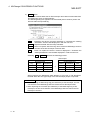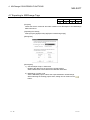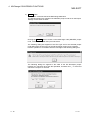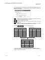
1
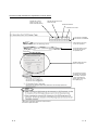
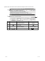
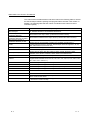
• SAFETY PRECAUTIONS •
(Always read these instructions before using this equipment.)
Before using this product, please read this manual and the relevant manuals introduced in this manual
carefully and pay full attention to safety to handle the product correctly.
The instructions given in this manual are concerned with this product. For the safety instructions of the
programmable controller system, please read the CPU module user's manual.
In this manual, the safety instructions are ranked as "DANGER" and "CAUTION".
DANGER
Indicates that incorrect handling may cause hazardous conditions,
resulting in death or severe injury.
! CAUTION
Indicates that incorrect handling may cause hazardous conditions,
resulting in medium or slight personal injury or physical damage.
!
Note that the ! CAUTION level may lead to a serious consequence according to the circumstances.
Always follow the instructions of both levels because they are important to personal safety.
Please save this manual to make it accessible when required and always forward it to the end user.
[Design Instructions]
!
DANGER
• When data change, program change or status control is to be made from a personal computer
to the running programmable controller CPU, configure up an interlock circuit in the outside of
the programmable controller system to ensure that the whole system will always operate safely.
Also, determine corrective actions to be taken for the system when a communication error
occurs due to a cable connection fault or the like in online operation performed from the
personal computer to the programmable controller CPU.
!
CAUTION
• Online operation performed with a personal computer connected to the running CPU module
(especially program change, forced output or operating status change) should be started after
carefully reading the manual and fully ensuring safety.
Not doing so can cause machine damage or accident due to miss operation.
A-1
A-1
REVISIONS
* The manual number is given on the bottom left of the back cover.
Print Date
* Manual Number
Jan., 2008
SH(NA)-080760ENG-A
Revision
First edition
This manual confers no industrial property rights or any rights of any other kind, nor does it confer any patent
licenses. Mitsubishi Electric Corporation cannot be held responsible for any problems involving industrial property
rights which may occur as a result of using the contents noted in this manual.
© 2008 MITSUBISHI ELECTRIC CORPORATION
A-2
A-2
INTRODUCTION
Thank you for choosing the Mitsubishi MELSOFT series Integrated FA software.
Read this manual and make sure you understand the functions and performance of MELSEC series
programmable controller thoroughly in advance to ensure correct use.
Please make this manual available to the end user.
CONTENTS
SAFETY PRECAUTIONS...............................................................................................................................A- 1
REVISIONS .....................................................................................................................................................A- 2
INTRODUCTION.............................................................................................................................................A- 3
CONTENTS.....................................................................................................................................................A- 3
Manuals ...........................................................................................................................................................A- 4
How the manual describes the explanation is shown below .........................................................................A- 5
Abbreviations and Terms in This Manual.......................................................................................................A- 7
1. GENERAL DESCRIPTION
1- 1 to 1- 3
1.1 Features ................................................................................................................................................... 1- 1
1.2 Function List ............................................................................................................................................. 1- 3
2. SYSTEM CONFIGURATION
2- 1 to 2- 2
2.1 Connecting from the Serial Port .............................................................................................................. 2- 1
2.2 System Equipment................................................................................................................................... 2- 1
3. ACCESSING TO SX Controller
3- 1 to 3- 4
3.1 Accessing from Personal Computer........................................................................................................ 3- 2
3.2 Accessing from GX Developer that Operates on PC CPU Module ....................................................... 3- 4
4. MXChange CONVERSION FUNCTIONS
4- 1 to 4- 15
4.1 Function List ............................................................................................................................................. 4- 1
4.2 General Procedure for Using the MXChange Conversion Functions ................................................... 4- 3
4.3 Logging in to the Server........................................................................................................................... 4- 4
4.4 Logging off the Server.............................................................................................................................. 4- 6
4.5 MXChange Data Base Conversion ......................................................................................................... 4- 7
4.6 Importing from MXChange Tags ............................................................................................................. 4- 9
4.7 Exporting to MXChange Tags ................................................................................................................. 4-11
4.8 MXChange Troubleshooting.................................................................................................................... 4-15
APPENDIX
App- 1 to App- 4
Appendix 1 Restrictions on Using SX Controller.......................................................................................App- 1
Appendix 2 Accessing to MAC ..................................................................................................................App- 2
Appendix 3 Restrictions When Changing CPU Types..............................................................................App- 3
A-3
A-3
Manuals
The following lists the manuals for this software package.
Refer to the following table when ordering manuals.
Related Manuals
Manual Name
GX Developer Version 8 Operating Manual
Explains the online functions of GX Developer, such as the programming, printout, monitoring and
debugging methods.
GX Developer Version 8 Operating Manual (Startup)
Describes the system configuration, installation method and start-up procedure of GX Developer.
Manual Number
(Model Code)
SH-080373E
(13JU41)
SH-080372E
(13JU40)
REMARKS
Manuals in printed form are sold separately for single purchase.
Order a manual by quoting the manual number (model code) listed in the table above.
A-4
A-4
How the manual describes the explanation is shown below
Indicates the A series,
QCPU (A mode), and
Motion Controller (SCPU).
Indicates the QnA series and
QCPU (Q mode).
Indicates the QSCPU.
Indicates the FX series.
: The function is available.
: The function is unavailable.
Items which are set in the
section are explained.
The desired window opens
by selecting the items in
the specified order.
The dialog boxes set in the
section are explained.
The contents of the items
and buttons are explained.
The numbers correspond
to those specified in the
window shown under the
title of [Dialog box].
This gives the information related to the topic discussed
and also the helpful information.
A-5
A-5
Symbols used in this manual, and the contents and examples of them are shown below.
1)
2)
3)
4)
No.
1)
Symbol
[
]
4)
A-6
Menu name of menu bar
Example
[Project]
Icon in toolbar
2)
3)
Contents
<<
>>
Tab name of dialog box
Command button in dialog box
<<Program common>>
lOKl button
A-6
Abbreviations and Terms in This Manual
This manual uses the abbreviations and terms listed in the following table to discuss
the GX Developer software package and programmable controller CPU module. In
addition, the following table lists the names of modules whose names must be
indicated explicitly.
Abbreviation/Generic term
GX Developer
GX Developer Version n
(SWnD5C-GPPW-E)
GX Developer Version n
(SWnD5C-GPPW-E) or earlier
GX Developer Version n
(SWnD5C-GPPW-E) or later
Description/Target module
Generic product name of the product types SW8D5C-GPPW-E, SW8D5C-GPPWEA, SW8D5C-GPPW-EV and SW8D5C-GPPW-EVA.
When limited to the major version (n denotes the version number).
When limited to earlier than the major version (n denotes the version number).
When limited to later than the major version (n denotes the version number).
ACPU
Generic term for programmable controller CPU available with MELSEC-A.
Including MOTION (SCPU). (However, GX Developer does not support A1, A2, A3,
A3H, A3M, A52G, A73, A0J2 and A3V.)
QCPU (A mode)
Generic term for Q02(H)-A and Q06H-A.
QnACPU
Generic term for programmable controller CPU available with MELSEC-QnA.
QCPU (Q mode)
Generic term for Q00J, Q00, Q01, Q02(H), Q02U, Q03UD, Q04UDH, Q06H,
Q06UDH, Q12H, Q12PH, Q12PRH, Q25H, Q25PH and Q25PRHCPU.
QSCPU
Abbreviation for a safety CPU module (QS001CPU).
FXCPU
Generic term for programmable controller CPU available with MELSEC-F. (The target
programmable controller CPUs are FX0, FX0S, FX0N, FX1, FX, FX2, FX2C, FX1S, FX1N,
FX2N, FX2NC, FX3U and FX3UC.)
A series
For GX Developer CPU type selection by ACPU.
QnA series
For GX Developer CPU type selection by QnACPU.
Q series
For GX Developer CPU type selection by QCPU (Q mode).
FX series
For GX Developer CPU type selection by FXCPU.
A6TEL
A6TEL modem interface module
Q6TEL
GOT
SX Controller
A-7
Q6TEL modem interface module
Generic term for Mitsubishi Graphic Operation Terminal GOT1000 series, GOT-A900
series and GOT-F900 series.
Generic product name of the product types SWnPNC-Q25SS-E.
(n denotes the version number)
A-7
1 GENERAL DESCRIPTION
MELSOFT
1. GENERAL DESCRIPTION
1
This manual explains the special functions of GX Developer designed exclusively for
overseas use.
1.1 Features
The following explains the features of GX Developer designed exclusively for
overseas use.
(1) Accessibility to SX Controller
SX Controller is software designed to operate on a PC CPU module.
By executing the program written with GX Developer, SX Controller makes Q bus
access and achieves sequence control using the device data that the software
itself has.
User appliation
(Microsoft Visual Basic ,
Microsoft Visual C++ )
MELSEC
commucation function
QSS function
Parameter
Interpreting,
Sequence
execution
program
Device
data
SX Controller
Q bus access
GX Developer
PC CPU
module
1-1
Hard disk unit
Personal computer
1-1
1 GENERAL DESCRIPTION
MELSOFT
(2) Featured with the MXChange conversion functions
Device comment data created in the GX Developer project can be shared with
other applications by using the MXChange conversion functions.
GPPW Project
MXChange structure
Comment
A Project
Device Comment
COMMENT
Alias
X0
Y0
D0
W0
M0
sw1
out1
value1
amount1
initial1
Sample1
Sample2
Sample3
Sample4
Sample5
Tag name
Comment
Sample1
Sample2
Sample3
Sample4
Sample5
MAIN
M0
X0
Y0
D0
W0
Sample1
Sample2
Sample3
Sample4
Sample5
initial2
sw2
out2
value2
amount2
Sample1
Sample2
Sample3
Sample4
Sample5
Q Project
Device Comment
COMMENT
M0
X0
Y0
D0
W0
Sample1
Sample1
Sample2
Sample3
Sample4
Sample5
initial1
sw1
out1
value1
amount1
Sample2
Sample3
Sample4
Sample5
Sample1
MAIN
M0
Sample1
initial2
(3) Accessibility to MAC
MAC can be accessed by using the RS-232C serial communications.
1-2
1-2
1
1 GENERAL DESCRIPTION
MELSOFT
1.2 Function List
The following table shows the function menus for GX Developer designed exclusively
for overseas use.
Tool (Common functions)
MXChange actions
Log in
Log out
Change Password
1-3
Log in to MXChange Server.
Log off MXChange Server.
Changes password in MXChange Server.
Only for
monitoring
Reference
4.3
4.4
4.3
1-3
2 SYSTEM CONFIGURATION
MELSOFT
2. SYSTEM CONFIGURATION
The following figure shows the system configuration of GX Developer designed
exclusively for overseas use.
2.1 Connecting from the Serial Port
GX Developer
(SW8D5C-GPPW)
Programmable controller
direct coupled
(USB communication)
2
1
SX Controller
(PC CPU module)
RS-232
1: PC CPU module compatible RS-232 cable
PC CPU module side
Cable connection and signal direction
Personal
computer
Signal name
Pin No.
Signal name
CD
1
CD
RD(RXD)
2
RD(RXD)
SD(TXD)
3
SD(TXD)
DTR(ER)
4
DTR(ER)
SG
5
SG
DSR(DR)
6
DSR(DR)
RS(RTS)
7
RS(RTS)
CS(CTS)
8
CS(CTS)
2.2 System Equipment
The following table shows the module that can be accessed to/from GX Developer
designed exclusively for overseas use.
Programmable controller
CPU series
Q series
2-1
Module name
Programmable controller CPU module
Module model
Q25SS
2-1
2 SYSTEM CONFIGURATION
MELSOFT
MEMO
2
2-2
2-2
3 ACCESSING TO SX Controller
MELSOFT
3. ACCESSING TO SX Controller
A
Q/QnA
QS
FX
: Compatible with the Q25SS.
This chapter explains the method for accessing to the SX Controller from the
personal computer and GX Developer that operates on a PC CPU module.
Accessing from personal computer
QCPU
3
PC CPU module MELSECNET/H
CC-Link
SX Controller
QCPU
MELSECNET/H
CC-Link
Accessing from GX Developer that operates on PC CPU module
PC CPU module
GX Developer
MELSECNET/H
CC-Link
QCPU
SX Controller
QCPU
3-1
MELSECNET/H
CC-Link
3-1
3 ACCESSING TO SX Controller
MELSOFT
3.1 Accessing from Personal Computer
A
Q/QnA
QS
FX
: Compatible with the Q25SS.
[Purpose]
For the access to the SX Controller, connection can be made in any of the following
routes.
1) Connect through the QCPU (Q mode) module
2) Connect from a personal computer to the SX Controller
3) Connect via MELSECNET/H or CC-Link on another station
3
1)
QCPU
2)
PC CPU module MELSECNET/H
CC-Link
SX Controller
QCPU
MELSECNET/H
CC-Link
3)
[Operating Procedure]
Select [Online] [Connection setup].
[Dialog Box]
When the personal computer is connected to the RS-232 port of the PC CPU
module (In the case of 2))
3-2
3-2
3 ACCESSING TO SX Controller
MELSOFT
[Description]
• For "PC side I/F", select the port, interface board or the like used with the
personal computer.
• For "PLC side I/F", select the module to be connected to the personal computer.
• Refer to the GX Developer Operating Manual for setting "Other station", "Network
route", and "Co-existence network route".
• You cannot select the following route.
You cannot select the Q-compatible C24 or
Q-compatible E71 route of the module
controlled by the SX Controller.
QCPU
PC CPU module Q-compatible C24
Q-compatible E71
SX Controller
QCPU
3-3
Q-compatible C24
Q-compatible E71
3-3
3 ACCESSING TO SX Controller
MELSOFT
3.2 Accessing from GX Developer that Operates on PC CPU Module
A
Q/QnA
QS
FX
: Compatible with the Q25SS.
[Purpose]
When GX Developer is installed in the PC CPU module, data can be accessed to
the SX Controller or to another station through SX Controller via MELSECNET/H or
CC-Link.
PC CPU module
GX Developer
MELSECNET/H
CC-Link
QCPU
SX Controller
QCPU
MELSECNET/H
CC-Link
[Operating Procedure]
Select [Online] [Connection setup].
[Dialog Box]
When accessing to another station through SX Controller via MELSECNET/H
[Description]
You cannot select the Q-compatible C24 or Q-compatible E71 route of the module
controlled by the SX Controller.
3-4
3-4
4 MXChange CONVERSION FUNCTIONS
MELSOFT
4. MXChange CONVERSION FUNCTIONS
The MXChange conversion functions are designed to share the device comment
data of GX Developer project among applications.
Programs, device memory and others cannot be converted.
4.1 Function List
A
Q/QnA
QS
FX
The following functions can be performed on GX Developer.
Function
Description
MXChange data base
comment read
GX Developer device
MXChange data base
comment write
GX Developer device
4
The tag information of the MXChange data base is read onto GX
Developer and converted into GX Developer device comments.
(Refer to Section 4.6)
GX Developer device comments are converted into the tag
information of the MXChange data base and the results are written
to the MXChange data base. (Refer to Section 4.7)
MXChange server designation
Among multiple MXChange data bases, specify the data base
server which reads/writes the device comment data of GX
Developer. (Refer to Section 4.3)
Tag change notice
When the MXChange data base is updated from another
application, it can be confirmed that the tag information has been
changed. (Refer to Section 4.3)
Password setting
Set the password used when you log in to the MXChange server.
(Refer to Section 4.3)
The following table lists the devices supported.
For MXChange 1.1b
• Bit devices
M
SM
Special
M
S
L
F
V
X
Y
B
SB
DX
DY
BL
ZR
W
SW
T
C
ST
P
I
U
J
QCPU (Q mode)
QnACPU
ACPU
FXCPU
• Word devices
D
SD
Special
D
R
QCPU (Q mode)
QnACPU
ACPU
FXCPU
4-1
4-1
4 MXChange CONVERSION FUNCTIONS
MELSOFT
For MXChange 2.1
• Bit devices
M
SM
Special
M
S
L
F
V
X
Y
B
SB
DX
DY
BL
ZR
W
SW
T
C
ST
P
I
U
J
Q02(H)/Q06/
Q12H/Q25HCPU
Q00J/Q00/
Q01CPU
QnACPU
ACPU
FXCPU
• Word devices
4
D
SD
Special
D
R
Q02(H)/Q06/
Q12H/Q25HCPU
Q00J/Q00/
Q01CPU
*1
*1
QnACPU
ACPU
FXCPU
1: R and ZR cannot be used for the Q00JCPU.
4-2
4-2
4 MXChange CONVERSION FUNCTIONS
MELSOFT
4.2 General Procedure for Using the MXChange Conversion Functions
A
Q/QnA
QS
FX
Start
Install GPPW 's MXChange
conversion functions and
MXChange 1. 1b.
Refer to the Startup manual for
GPPW installation.
....... Refer to the manual supplied with
MXChange 1.1b for MXChange
1.1b installation.
Start the MXChange server.
........Start from the MXChange group
in the Start menu of Windows R .
After starting GPPW, log in to
the MXChange server.
Set the server name.
Set the password.
When selecting Import file.
Make the Import from
MXChange tags setting.
........ Refer to Section 4.3.
When selecting Export file.
........Refer to Section 4.6.
Log off the server.
Make the Export to
MXChange tags setting.........Refer to Section 4.7.
........Refer to Section 4.4.
Exit from GPPW
4-3
4-3
4 MXChange CONVERSION FUNCTIONS
MELSOFT
4.3 Logging in to the Server
A
Q/QnA
QS
FX
[Purpose]
Enables use of the MXChange data base conversion functions.
Menu selection cannot be made unless the project is open on GX Developer.
[Operating Procedure]
Select [Tool] [MXChange actions]
[Login].
[Dialog Box]
[Description]
1) Server Name
Type the MXChange server name (or IP address) to which GX Developer is
connected.
2)
Use Local Address button
The computer name in current use is set as the Server Name.
3)
Browse button
A connectable server list is displayed.
Select the Server Name and click the Select button.
4) Time Out
Set the time-out value when making connection to the server.
The range setting is 0 to 200000ms.
5) User Name
Defaults to Admin.
The User Name cannot be changed.
4-4
4-4
4 MXChange CONVERSION FUNCTIONS
MELSOFT
6) Password
Set the password (max. 1024 characters) used when making connection to the
server with the specified login name.
How to set the password change.
1. Select [Tool] [MXChange actions] [Password].
2. In "Old Password", set the password currently used.
In "New Password" and "Retype", set a new password.
3. Click the OK button.
7) Option
When any change has been made to the data of the MXChange data base, GX
Developer receives that change and you can confirm it in the following dialog
box.
Clicking the Show Changes button displays the following screen.
Item
Description
Any of the following is displayed.
When changes were made to the project node:
Class Name
Node Name
MXChange Project Name
• MELSEC project (A)
• MELSEC project (QnA)
• MELSEC project (Q)
• MELSEC project (Motion)
• MELSEC project (FX)
When changes were made to the tag:
• MM+ I/O Reference
Displays node names of GX Developer that are
changed.
Displays project names that are changed.
Any of the following is displayed.
• deleted: The displayed node or tag was erased from
another application.
Changes
• modified: Comment data of the displayed node or tag
that was erased from another application are
changed.
• added:
4-5
Additions were made to the displayed node
or tag from another application.
4-5
4 MXChange CONVERSION FUNCTIONS
MELSOFT
4.4 Logging off the Server
A
Q/QnA
QS
FX
[Purpose]
Stops connection to the MXChange server.
[Operating Procedure]
Select [Tool] [MXChange actions]
4-6
[Logoff].
4-6
4 MXChange CONVERSION FUNCTIONS
MELSOFT
4.5 MXChange Data Base Conversion
A
Q/QnA
QS
FX
This section explains correspondences between the GX Developer project data and
MXChange data base data for execution of MXChange data base conversion.
GPPW Project
MXChange structure
Comment
A Project
Device Comment
COMMENT
Alias
X0
Y0
D0
W0
M0
sw1
out1
value1
amount1
initial1
Sample1
Sample2
Sample3
Sample4
Sample5
Tag name
Comment
Sample1
Sample2
Sample3
Sample4
Sample5
MAIN
M0
X0
Y0
D0
W0
Sample1
Sample2
Sample3
Sample4
Sample5
initial2
sw2
out2
value2
amount2
Sample1
Sample2
Sample3
Sample4
Sample5
Q Project
Device Comment
COMMENT
M0
X0
Y0
D0
W0
Sample1
Sample1
Sample2
Sample3
Sample4
Sample5
initial1
sw1
out1
value1
amount1
Sample2
Sample3
Sample4
Sample5
Sample1
MAIN
M0
Sample1
initial2
In the MXChange data base, the comment types of the GX Developer device
comments correspond to the respective project nodes (FX Project (COMMENT), Q
Project (MAIN), etc.).
4-7
4-7
4 MXChange CONVERSION FUNCTIONS
MELSOFT
For importing data from MXChange server to GX Developer, the data names
correspond as indicated below.
MXChange tag
GX Developer Project
Tag name
Alias
Device
Device
Comment
Comment
For exporting data from GX Developer to MXChange server, the data names
correspond as indicated below.
GX Developer Project
MXChange tag
Device
Device
Comment
Comment
Label
Tag name
POINT
• When the Alias created on GX Developer is exported to the MXChange data
base, do not use any characters other than the alphabets, numerals and "_".
In addition, do not enter a space or numeral at the beginning of the Label.
• If nothing has been set to the Alias of GX Developer at the time of Export,
Device changes to Tag name.
4-8
4-8
4 MXChange CONVERSION FUNCTIONS
MELSOFT
4.6 Importing from MXChange Tags
A
Q/QnA
QS
FX
[Purpose]
Reads comment data in the MXChange server.
[Operating Procedure]
Select [Project] [Import file]
[Import from MXChange tags].
[Dialog Box]
[Description]
1) MXChange : Project Node
Set the MELSEC project node.
button.
Set the item from the
2) GX Developer Project : Data name
Select from the displayed data names that exist in the currently opened GX
Developer project.
4-9
4-9
4 MXChange CONVERSION FUNCTIONS
MELSOFT
3) Import button
Deletes all comment data exist on GX Developer and reads comment data from
the MXChange server to GX Developer.
The following dialog box appears if the same data (device number) exist in the
devices within the imported tag.
Yes
:Replaces the device comment displayed in "Overwrite the existing
declaration" with the data displayed in "with the new one".
Yes all :Replaces all data with the newly read data.
No all :Does not replace data if the tag name read from MXChange exists in
the Alias of the GX Developer comment data.
No
:Does not replace the device comment displayed in "Overwrite the
existing declaration" with the data displayed in "with the new one".
Selecting Yes or Yes all performs the following process.
After Import
MXChange Data
GX Developer Data
Tag
Device
COMMENT
Device
COMMENT
Alias
TAG1
D100
Sample1
D100
Sample3
TAG3
M0
Sample2
TAG2
TAG2
M0
Sample2
TAG3
D100
Sample3
TAG1 D100 Sample1 is overwritten by TAG3 D100 Sample3.
When importing the MXChange data different in CPU type on GX Developer,
the data within the CPU type range of the GX Developer project is imported.
POINT
• When importing the MXChange tag (64 characters) to GX Developer, the first
8 characters of the MXChange data are read to the GX Developer Alias.
• When importing the comment (64 characters) of the MXChange tag to GX
Developer, the first 32 characters of the MXChange data are read to the GX
Developer comment.
4 - 10
4 - 10
4 MXChange CONVERSION FUNCTIONS
MELSOFT
4.7 Exporting to MXChange Tags
A
Q/QnA
QS
FX
[Purpose]
Writes the device comments and Alias created on GX Developer to the MXChange
data base server.
[Operating Procedure]
Select [Project] [Export file]
[Export to MXChange tags].
[Dialog Box]
[Description]
1) GX Developer Project : Data name
Displays the data name of the project currently edited.
Set the data name to be written to the MELSEC data base.
2) MXChange : Project node
Set the MELSEC project node at the export destination of MXChange.
When selecting the existing project node, setting can be made from the
button.
4 - 11
4 - 11
4 MXChange CONVERSION FUNCTIONS
MELSOFT
3) Export button
Converts the comment data of the MXChange data base.
The following dialog box appears if the MELSEC project node set on the Export
Settings screen does not exist.
Clicking the Create button creates a new MXChange node (MELSEC project
node, comment node) with the input node name.
The following dialog box appears if the CPU type set for the selected project
node differs from the CPU type of the GX Developer project to be exported.
Perform operation in accordance with the message of the following dialog box.
The following dialog box appears if the Alias of the GX Developer project
includes any character other than the alphabets, numerals and "_" or if the first
character is a space or numeral.
4 - 12
4 - 12
4 MXChange CONVERSION FUNCTIONS
MELSOFT
The following dialog box appears if the same tag name already exists in the
MXChange data base or if overlapping data exist in the device comments or
aliases of GX Developer.
Yes
:Replaces the tag displayed in "Overwrite the existing declaration"
with the tag displayed in "with the new one".
Yes all :Replaces all data with new data.
No all :Does not replace data if the same tag name exists at the write
destination.
No
:Does not replace the tag displayed in "Overwrite the existing
declaration" with the tag displayed in "with the new one".
Selecting Yes or Yes all performs the following process.
Before Export
GX Developer Data
Device
COMMENT
M0
Sample1
MXChange Data
Alias
Tag
Device
COMMENT
Tag2
Tag1
D64
Sample1
SW2
Tag2
M0
Sample2
Sample2
Tag5
Tag3
X0
Sample3
Tag4
Y0
Sample4
W0
Sample3
SW2
Tag5
D64
Sample5
T10
Sample6
X0
D64
Y50
After Export
MXChange Data
Tag
Device
COMMENT
Tag2
M0
Sample1
SW2
W0
Sample3
Tag5
D64
Sample2
T10
T10
Sample6
• Y50 of GX Developer is not exported since it has no COMMENT and Alias.
• If there is no data set in Alias of GX Developer at the time of Export, the
device changes to the tag name.
4 - 13
4 - 13
4 MXChange CONVERSION FUNCTIONS
MELSOFT
Exporting the data in the preceding table shows the following dialog box.
The following dialog box appears since Tag5 D64 Sample2 exists in the GX
Developer data and Tag5 D64 Sample5 exists in the MXChange data.
Since more than one SW2 exists as the Alias of the GX Developer data, the
following dialog box appears.
4 - 14
4 - 14
4 MXChange CONVERSION FUNCTIONS
MELSOFT
4.8 MXChange Troubleshooting
The following table shows error messages and their corrective actions.
Error message
Corrective action
"The connection to the MXChange server timed out!"
Increase the time-out value in the Login dialog box.
"The MXChange server has been disconnected!"
Start the MXChange server or log in again.
"Not logged in, or insufficient right to perform the action!"
Type the password correctly.
"Logoff incorrect!
Make sure that the server has been started.
confirmed (error code number)"
Inform the developer of the error code.
"Close Connection unsuccessful!
Make sure that the server has been started.
confirmed (error code number)"
Inform the developer of the error code.
"The server has no current database!"
Create a new data base in the MXChange server.
"The request object dose not exist!"
Start the MXChange server.
"Please input the Project node."
Set the project of the export destination.
"Comment data was not found."
Create a new comment data name on GX Developer.
"The old password was incorrect."
Set a correct password.
"Licencing limits exceeded."
Export within the permitted number of tags.
"The PLC type of the exporting project node differs with
the PLC type of the actual project. Please create a new
Project node or specify the project node having the PLC
type same as the project."
Create a new project of the export destination separately,
or choose the project of the same CPU type as that of GX
Developer for the export destination.
"MXChange server Disconnect!"
Start the MXChange server or log in again.
"Bad 1st character of MXChange tag name."
Using correct characters, re-set the tag name.
"The connection is broken. Processing is canceled.
A partial data was Exported."
Log in to the server again.
"Project is already used by user!"
Execute after logging off MXChange in the corresponding
application.
"Project node is not exist in MXChange server!"
Perform operation after create the MELSEC project node.
"This PLC type is not available in MXChange."
An attempt was made to export the comment data of the
CPU type of the GX Developer project not supported by
MXChange.
Choose the MXChange Project node of the same CPU
type as that of GX Developer Project at Export.
4 - 15
4 - 15
APPENDIX
MELSOFT
APPENDIX
App.
Appendix 1 Restrictions on Using SX Controller
This chapter explains the restrictions on functions of GX Developer when using SX
Controller.
(1) Restrictions on PLC parameter
•
•
"Compatibility with A-PLC" on <<PLC system>> cannot be set.
"Low speed program execution time" on <<PLC RAS>> cannot be set.
(2) Restriction on network parameter
Ethernet parameter cannot be set.
(3) Restrictions on program list monitor
•
•
"Monitor time" fields of "Total scan time" are masked.
"Low speed program" field of "Scan execution part, detailed scan time" is
masked.
(4) Restriction on sampling trace
The setting range when "Interval" is selected for the "Trace point setup", is as
follows.
CPU type
SX Controller
Range
1 to 5000ms
Unit
1ms
(5) Restriction on Ethernet diagnostics
Ethernet diagnostics cannot be executed when Q25SS is selected for CPU type.
(6) Restrictions on system monitor
Appendix - 1
•
Installed status
The CPU type name is not displayed when SX Controller is not operated on a
PC CPU. (The field is displayed blank.)
•
PLC diagnostics button
Ethernet diagnostics cannot be executed when SX Controller is selected as a
CPU type on GX Developer.
Appendix - 1
APPENDIX
MELSOFT
Appendix 2 Accessing to MAC
The following shows the setting when accessing to MAC by using RS-232C serial
communications.
1. Select RS-232C and click the Setup button on the "PC side I/F Serial setting" of the
"Transfer Setup" screen.
2. Set "Parity", "Data Bits", and "Stop Bits" on the "Transfer Setup: PC side I/F Serial
Setting" screen.
Note that, if the project with this setting is opened by GX Developer Version 8.04E or
earlier, the setting is discarded.
If the project created by GX Developer Version 8.04E or earlier is opened by
GX Developer Version 8.05F or later, the default setting is displayed.
POINT
• Set "via MAC/MTA transparent mode" on the "PLC side I/F Detailed setting of
PLC module" screen only when MAC/MTA is used.
Appendix - 2
Appendix - 2
App.
APPENDIX
MELSOFT
Appendix 3 Restrictions When Changing CPU Types
The following table shows the restrictions when changing CPU types between QCPU
(Q mode) and Q25SS.
Restrictions
Q25SS
Q25SS
QCPU (Q mode)
QCPU (Q mode)
Instructions • Incompatible instructions are converted into SM999.
• No restrictions
• Incompatible devices (SM1024/SD1024 and later)
(Since Q25SS-dedicated instructions, if converted, do
are
converted
into
SD999.
Programs
not result in errors, perform a program check and
Devices
• When the program is converted into a Q00J
correct the program after conversion.)
program, file registers (R, ZR) are converted into
SD999.
Device memory
• No restrictions
• No restrictions
Device comments
PLC parameters
• Remote password is deleted.
• No restrictions
Network parameters
MELSECNET/H
• No restrictions
• No restrictions
MELSECNET/10
CC-Link
• No restrictions
• No restrictions
---Ethernet
• Ethernet setting is deleted.
Item
Appendix - 3
Appendix - 3
APPENDIX
MELSOFT
MEMO
Appendix - 4
Appendix - 4
Microsoft Windows, Microsoft Windows NT are registered trademarks of Microsoft Corporation in the
United States and other countries.
Pentium is a registered trademark of Intel Corporation in the United States and other countries.
Other company and product names herein are either trademarks or registered trademarks of their
respective owners.
SPREAD
Copyright (C) 1998 Farpoint Technologies, Inc.
SH(NA)-080760ENG-A