1
O
Operating Manual
Operating Manual
GX Developer Version7 Operating Manual
MODEL
SW7D5-GPPW-O-E
MODEL
CODE
13JU14
SH(NA)-080166-A(0106)MEE
HEAD OFFICE : MITSUBISHI DENKI BLDG MARUNOUCHI TOKYO 100-8310 TELEX : J24532 CABLE MELCO TOKYO
NAGOYA WORKS : 1-14 , YADA-MINAMI 5 , HIGASHI-KU, NAGOYA , JAPAN
When exported from Japan, this manual does not require application to the
Ministry of Economy, Trade and Industry for service transaction permission.
Specifications subject to change without notice.
SW7D5C-GPPW-E
• SAFETY PRECAUTIONS •
(Always read these instructions before using this equipment.)
Before using this product, please read this manual and the relevant manuals introduced in this manual
carefully and pay full attention to safety to handle the product correctly.
The instructions given in this manual are concerned with this product. For the safety instructions of the
programmable controller system, please read the CPU module user's manual.
In this manual, the safety instructions are ranked as "DANGER" and "CAUTION".
DANGER
Indicates that incorrect handling may cause hazardous conditions,
resulting in death or severe injury.
! CAUTION
Indicates that incorrect handling may cause hazardous conditions,
resulting in medium or slight personal injury or physical damage.
!
Note that the ! CAUTION level may lead to a serious consequence according to the circumstances.
Always follow the instructions of both levels because they are important to personal safety.
Please save this manual to make it accessible when required and always forward it to the end user.
[Design Instructions]
!
DANGER
• For data change, program change, and status control made to the PLC which is running from a
Personal computer, configure the interlock circuit externally so that the system safety is
ensured.The action to be taken for the system at the occurrence of communication errors
caused by such as loose cable connection must be determined for online operation of PLC from
Personal computers.
!
CAUTION
• Be sure to read the manual careful and exercise an appropriate amount of caution connecting to
PLC CPU and performing online operations (PLC CPU program change during RUN, forced
input/output operation, RUN-STOP or other operation condition changes, remote control
operation) while the personal computer is operating.
Regarding the PLC CPU program change during RUN (Write during RUN), the program may be
corrupted or have other problems depending on operation conditions. Exercise the appropriate
amount of caution with regard to the Caution points in section 16.9.
• Please refer to the manual of each module for online module change and swap module during
run, since there is restriction on the exchangeable module.
A-1
A-1
Revisions
The manual number is given on the bottom left of the back cover.
Print Date
Jun.,2001
Dec.,2001
Manual Number
SH(NA)-080166-A
SH(NA)-080166-B
Revision
First edition
Addition
SAFETY PRECAUTIONS, Section1.1, Section2.2, Section2.3,
Section2.5.4, Section4.14,
Section9.1, Section13.1, Section13.1.1, Section13.1.2,
Section13.2.2, Section16.1, Section16.2.4, Section16.3.1,
Section16.3.2, Section21.5, Section21.6, Appendix 4
Correction
Abbreviations and Terms in This Manual, Section3.2.1, Section11.2,
Section Chapter 12, Section13.2,
Section16.9, Section17.8, Section21.1.2, Section21.3.1,
Section21.3.2, Section21.3.3, Section21.4.1
Jun.,2002
SH(NA)-080166-C
Addition
Section1.1, Section3.13.2, Section5.1.4, Section14.5.6, Section16.2.4,
Section16.3.1, Section16.3.2, Section21.1.2, Section21.3,
Section21.3.1, Section21.3.2, Section21.3.3, Section21.4.9,
Section22.2.3, Section22.3.5, Appendix 8, Appendix 9, Appendix 10
Correction
Section 2.3,Section3.13.2, Section4.18, Section5.1.4, Section9.1,
Section13.1.1, Section13.1.2, Section15.14, Section16.2.2,
Section16.2.3(2), Section16.2.4, Section 21.2.8, Section21.4.1,
Section22.3.1, Section22.4.2, Appendix 4, Appendix 10
Oct.,2002
SH(NA)-080166-D
Addition
Section2.5.4, Section16.3
Correction
Appendix 9
Nov.,2002
SH(NA)-080166-E
Addition
Section4.7, Section16.4
Correction
Section16.1.2
Japanese Manual Version SH-080160-F
This manual confers no industrial property rights or any rights of any other kind, nor does it confer any patent
licenses. Mitsubishi Electric Corporation cannot be held responsible for any problems involving industrial property
rights which may occur as a result of using the contents noted in this manual.
2001 MITSUBISHI ELECTRIC CORPORATION
A-2
A-2
INTRODUCTION
Thank you for choosing the Mitsubishi MELSOFT series Integrated FA software.
Read this manual and make sure you understand the functions and performance of MELSEC series
sequencer thoroughly in advance to ensure correct use.
Please make this manual available to the end user.
CONTENTS
SAFETY PRECAUTIONS..............................................................................................................................A - 1
REVISIONS ....................................................................................................................................................A - 2
CONTENTS....................................................................................................................................................A - 3
About Manuals..............................................................................................................................................A - 13
How the manual describes the explanation is shown below ......................................................................A - 14
Abbreviations and Terms in This Manual ....................................................................................................A - 16
Chapter 1 GENERAL DESCRIPTION
1- 1 to 1- 13
1.1 Functions Lists ........................................................................................................................................ 1- 3
1.2 FX Series Programming......................................................................................................................... 1- 11
1.3 Basic Key Specifications........................................................................................................................ 1- 13
Chapter 2 SYSTEM CONFIGURATION
2- 1 to 2- 15
2.1 Connection from the Serial Port.............................................................................................................. 2- 1
2.2 Connection from the Interface Boards.................................................................................................... 2- 4
2.3 Connection from GX Developer Installed in PC CPU Module............................................................... 2- 6
2.4 System Equipment Lists ......................................................................................................................... 2- 7
2.5 Precautions for Handling Projects on the Earlier Versions................................................................... 2- 10
2.5.1 Using GX Developer Version 4 (SW4D5C-GPPW-E) or earlier to handle project ....................... 2- 10
2.5.2 Using GX Developer Version 5 (SW5D5C -GPPW-E) or earlier to handle project ...................... 2- 11
2.5.3 Using GX Developer Version 6 (SW6D5C-GPPW-E) or earlier to handle project ....................... 2- 12
2.5.4 Using GX Developer Version 7.09K (SW7D5C-GPPW-E) or earlier to handle project................ 2- 13
Chapter 3 COMMON OPERATIONS
3- 1 to 3- 24
3.1 List of Shortcut Keys and Access Keys.................................................................................................. 3- 1
3.2 Project Designation ................................................................................................................................. 3- 5
3.2.1 Saving a project................................................................................................................................ 3- 6
3.2.2 Opening a project ............................................................................................................................. 3- 9
3.3 Cut, Copy, and Paste............................................................................................................................. 3- 10
3.3.1 Cut and paste .................................................................................................................................. 3- 10
3.3.2 Copy and paste ............................................................................................................................... 3- 12
3.3.3 Notes on cutting, copying and pasting network parameters.......................................................... 3- 14
3.4 Toolbar.................................................................................................................................................... 3- 16
3.5 Status Bar............................................................................................................................................... 3- 17
3.6 Zooming in on or out of the Edit Screen................................................................................................ 3- 18
3.7 Project Data List ..................................................................................................................................... 3- 19
3.8 Comment Display................................................................................................................................... 3- 21
3.9 Statement Display .................................................................................................................................. 3- 21
3.10 Note Display ......................................................................................................................................... 3- 21
A-3
A-3
3.11 Alias Display......................................................................................................................................... 3- 22
3.12 Comment Format ................................................................................................................................. 3- 22
3.13 Alias format display .............................................................................................................................. 3- 23
3.13.1 Replace device name and display................................................................................................ 3- 23
3.13.2 Arrange with device and display................................................................................................... 3- 23
3.14 Setting the Number of Contacts .......................................................................................................... 3- 24
3.14.1 Displaying 9 contacts ..................................................................................................................... 3- 24
3.14.2 Displaying 11 contacts ................................................................................................................... 3- 24
Chapter 4 INITIALIZATION
4- 1 to 4- 32
4.1 Creating a Project.................................................................................................................................... 4- 1
4.2 Opening the Existing Project File ........................................................................................................... 4- 3
4.3 Closing a Project File .............................................................................................................................. 4- 5
4.4 Saving a Project ...................................................................................................................................... 4- 5
4.5 Saving a Project with a New Name ........................................................................................................ 4- 6
4.6 Deleting a Project.................................................................................................................................... 4- 6
4.7 Verifying Data in Projects........................................................................................................................ 4- 7
4.8 Copying a Project................................................................................................................................... 4- 10
4.9 Adding Data to a Project ........................................................................................................................ 4- 12
4.10 Copying Data within a Project.............................................................................................................. 4- 14
4.11 Deleting Data in a Project .................................................................................................................... 4- 15
4.12 Renaming Data in a Project................................................................................................................. 4- 16
4.13 Changing the Ladder and SFC with each other.................................................................................. 4- 17
4.14 Changing the PLC Type of a Project................................................................................................... 4- 18
4.15 Reading Other Format Files ................................................................................................................ 4- 20
4.15.1 Reading GPPQ, GPPA, FXGP(DOS) or FXGP(WIN) files.......................................................... 4- 20
4.15.2 Reading a MELSEC MEDOC format file (Printout)...................................................................... 4- 24
4.15.3 Reading a MELSEC MEDOC format file...................................................................................... 4- 25
4.16 Exporting GPPQ, GPPA, FXGP(DOS) or FXGP(WIN) Files.............................................................. 4- 27
4.17 Starting Multiple Projects ..................................................................................................................... 4- 31
4.18 Existing GX Developer......................................................................................................................... 4- 31
Chapter 5 STANDARDIZING THE PROGRAMS
5- 1 to 5- 30
5.1 Label Programming................................................................................................................................. 5- 1
5.1.1 Label programming sequence ......................................................................................................... 5- 6
5.1.2 Label program input method............................................................................................................ 5- 7
5.1.3 Making global variable/local variable setting ................................................................................... 5- 9
5.1.4 Making automatic device setting..................................................................................................... 5- 13
5.1.5 Deleting External ............................................................................................................................. 5- 14
5.1.6 All deletion ....................................................................................................................................... 5- 14
5.1.7 Importing device comments ............................................................................................................ 5- 15
5.1.8 Exporting to device comments........................................................................................................ 5- 16
5.1.9 Converting label programs into actual programs (Compile) .......................................................... 5- 18
5.1.10 Displaying the Device Program .................................................................................................... 5- 20
5.2 About Macros ......................................................................................................................................... 5- 21
5.2.1 Registering a macro ........................................................................................................................ 5- 23
5.2.2 Utilizing a macro .............................................................................................................................. 5- 25
5.2.3 Deleting a macro ............................................................................................................................. 5- 27
A-4
A-4
5.2.4 Displaying macro references .......................................................................................................... 5- 28
Chapter 6 CREATING CIRCUIT
6- 1 to 6- 50
6.1 Restrictions on Circuit Creation .............................................................................................................. 6- 7
6.1.1 Restrictions in circuit display window............................................................................................... 6- 7
6.1.2 Restrictions in circuit edit window .................................................................................................... 6- 8
6.2 Creating and Editing Circuits ................................................................................................................. 6- 12
6.2.1 Inputting contacts and application instructions............................................................................... 6- 12
6.2.2 Inputting lines (vertical and horizontal) ........................................................................................... 6- 14
6.2.3 Deleting contacts and application instructions ............................................................................... 6- 16
6.2.4 Deleting connecting lines ................................................................................................................ 6- 17
6.2.5 Inserting and deleting in circuit blocks............................................................................................ 6- 18
6.2.6 Inserting NOPs ................................................................................................................................ 6- 20
6.2.7 Deleting NOPs................................................................................................................................. 6- 20
6.2.8 Cutting, copying and pasting circuits .............................................................................................. 6- 21
6.2.9 Undo the last operation ................................................................................................................... 6- 23
6.2.10 Returning to the status after ladder conversion ........................................................................... 6- 24
6.3 Changing T/C Setting Values ................................................................................................................ 6- 25
6.4 Find and Replace ................................................................................................................................... 6- 27
6.4.1 Finding a device .............................................................................................................................. 6- 29
6.4.2 Finding an instruction ...................................................................................................................... 6- 31
6.4.3 Finding a step No. ........................................................................................................................... 6- 32
6.4.4 Finding a character string................................................................................................................ 6- 33
6.4.5 Finding a contact/coil....................................................................................................................... 6- 35
6.4.6 Finding data..................................................................................................................................... 6- 36
6.4.7 Replacing a device .......................................................................................................................... 6- 37
6.4.8 Replacing an instruction.................................................................................................................. 6- 39
6.4.9 Changing A and B contacts ............................................................................................................ 6- 41
6.4.10 Replacing a character string ......................................................................................................... 6- 42
6.4.11 Replacing the module's first I/O number ...................................................................................... 6- 44
6.4.12 Changing the statement or note type ........................................................................................... 6- 45
6.4.13 Replacing data............................................................................................................................... 6- 46
6.4.14 Searching for a contact coil........................................................................................................... 6- 47
6.4.15 Searching for a device-use instruction ......................................................................................... 6- 49
Chapter 7 CREATING INSTRUCTION LIST
7- 1 to 7- 11
7.1 Common Notes on Instruction List Creation .......................................................................................... 77.2 Creating a Program Instruction list ......................................................................................................... 77.2.1 Inputting a contact or application instruction ................................................................................... 77.2 2 Changing the existing program in overwrite mode.......................................................................... 77.2.3 Inserting or adding the existing program ......................................................................................... 77.2.4 Deleting the existing program list..................................................................................................... 77.2.5 Inserting NOPs ................................................................................................................................ 77.2.6 Deleting NOPs ................................................................................................................................. 77.3 Find and Replace .................................................................................................................................... 77.3.1 Finding a device ............................................................................................................................... 77.3.2 Finding an instruction ....................................................................................................................... 77.3.3 Finding a step No. ............................................................................................................................ 7A-5
A-5
1
3
3
4
5
6
7
7
8
8
8
8
7.3.4 Finding a character string................................................................................................................. 7- 8
7.3.5 Finding a contact/coil........................................................................................................................ 7- 8
7.3.6 Replacing a device ........................................................................................................................... 7- 8
7.3.7 Replacing an instruction................................................................................................................... 7- 8
7.3.8 Changing an A or B contact ............................................................................................................. 7- 9
7.3.9 Replacing a character string ............................................................................................................ 7- 9
7.3.10 Change module start address........................................................................................................ 7- 9
7.3.11 Changing the statement or note type ............................................................................................ 7- 9
7.3.12 Searching for a contact coil............................................................................................................ 7- 9
7.3.13 Searching for an instruction using a device................................................................................... 7- 9
7.4 Display .................................................................................................................................................... 7- 10
7.4.1 Displaying an Alias .......................................................................................................................... 7- 10
7.5 Switching Read and Write Modes ......................................................................................................... 7- 11
7.5.1 Switching to read mode................................................................................................................... 7- 11
7.5.2 Switching to write mode .................................................................................................................. 7- 11
7.5.3 Switching to circuit mode ................................................................................................................ 7- 11
7.6 Changing T/C Setting Values ................................................................................................................ 7- 11
Chapter 8 CONVERSION
8- 1 to 8- 2
8.1 Converting an Edit Program ................................................................................................................... 8- 1
8.2 Converting Multiple Edit Programs......................................................................................................... 8- 1
Chapter 9 SETTING DEVICE COMMENTS
9- 1 to 9- 28
9.1 Points to be Noted before Comment Creation with GX Developer ....................................................... 9- 1
9.1.1 Editing comments only on GX Developer........................................................................................ 9- 4
9.1.2 Writing to ACPU/GPPA file .............................................................................................................. 9- 6
9.1.3 Reading from ACPU/GPPA file........................................................................................................ 9- 7
9.1.4 Writing to QCPU(Qmode) QnACPU/GPPQ file .............................................................................. 9- 9
9.1.5 Reading from QCPU(Qmode) QnACPU ......................................................................................... 9- 9
9.1.6 Writing to FXCPU/FXGP(DOS), FXGP(WIN) file........................................................................... 9- 10
9.1.7 Reading from FXCPU/FXGP(DOS), FXGP(WIN) file .................................................................... 9- 11
9.2 List of Device Comments....................................................................................................................... 9- 12
9.3 Common Comments and Comments by Program................................................................................ 9- 13
9.4 Creating Device Comments................................................................................................................... 9- 16
9.4.1 Creating device comments on the device comment edit window.................................................. 9- 16
9.4.2 Creating device comments for the created circuit.......................................................................... 9- 18
9.4.3 Creating device comments after creating a circuit ......................................................................... 9- 19
9.4.4 Editing comments on the ladder editing screen ............................................................................. 9- 20
9.5 Deleting Device Comments ................................................................................................................... 9- 21
9.5.1 Deleting all device comments and Alias......................................................................................... 9- 21
9.5.2 Deleting display device comments and Alias ................................................................................. 9- 21
9.6 Setting Comment Types ........................................................................................................................ 9- 22
9.7 Setting Comment Ranges...................................................................................................................... 9- 24
Chapter 10 SETTING THE STATEMENTS AND NOTES
10- 1 to 10- 20
10.1 About the Statements/Notes............................................................................................................... 10- 1
10.2 About Merging Operation Procedure.................................................................................................. 10- 6
A-6
A-6
10.3 Creating and Deleting Statements ..................................................................................................... 10- 7
10.3.1 When editing the circuit window .................................................................................................. 10- 7
10.3.1(1) Creating statements in the circuit edit window........................................................................ 10- 7
10.3.1(2) Deleting statements in the circuit edit window........................................................................ 10- 8
10.3.2 When editing the list window........................................................................................................ 10- 9
10.3.2(1) Editing statements on the list edit window .............................................................................. 10- 9
10.3.2(2) Deleting statements on the list edit window...........................................................................10- 10
10.3.3 Creating statements in the statement edit mode .......................................................................10- 11
10.4 Creating and Deleting Notes..............................................................................................................10- 12
10.4.1 Creating notes on the circuit edit window...................................................................................10- 12
10.4.1 (1) Creating notes on the circuit edit window .............................................................................10- 12
10.4.1 (2) Deleting notes in the circuit edit window...............................................................................10- 13
10.4.2 Creating notes in the list edit window .........................................................................................10- 14
10.4.2 (1) Creating notes in the list edit window....................................................................................10- 14
10.4.2 (2) Deleting notes in the list edit window ....................................................................................10- 15
10.4.3 Creating notes in the note edit mode..........................................................................................10- 16
10.5 Batch-Editing the Statements/Notes .................................................................................................10- 17
Chapter 11 SETTING DEVICE MEMORY (DWR SETTING)
11- 1 to 11- 6
11.1 Device Memory ................................................................................................................................... 1111.2 Device Value Input .............................................................................................................................. 1111.3 All Clear ............................................................................................................................................... 1111.3.1 Clearing all devices ...................................................................................................................... 1111.3.2 Clearing all display devices.......................................................................................................... 1111.4 Making Fill Settings ............................................................................................................................. 11-
1
2
5
5
5
6
Chapter 12 SETTING DEVICE INITIALIZATION VALUES
12- 1 to 12- 2
Chapter 13 SETTING THE PARAMETERS
13- 1 to 13- 26
13.1 Setting the PLC Parameters............................................................................................................... 13- 3
13.1.1 Common Notes on Parameters ................................................................................................... 13- 4
13.1.2 PLC Parameter Item Lists............................................................................................................ 13- 7
13.1.3 Explanations for PLC Parameter Setting Screen.......................................................................13- 16
13.2 Setting the Network Parameters........................................................................................................13- 17
13.2.1 About Items Common to the Network Parameters ....................................................................13- 18
13.2.2 Network Parameter Item Lists ....................................................................................................13- 20
13.2.3 Explanations for Network Parameter Setting Screen ................................................................13- 25
13.3 Setting the Remote Password ............................................................................................................13- 26
Chapter 14 PRINT
14- 1 to 14- 37
14.1 Setting Up a Printer............................................................................................................................. 14- 2
14.2 Setting a Page Layout......................................................................................................................... 14- 4
14.3 Previewing a Print Image.................................................................................................................... 14- 7
14.4 Printing................................................................................................................................................. 14- 9
14.5 Setting the Details for Printing ...........................................................................................................14- 12
14.5.1 Creating a title .............................................................................................................................14- 12
A-7
A-7
14.5.2 Setting a ladder print range.........................................................................................................14- 13
14.5.3 Setting a Instruction list print range ............................................................................................14- 16
14.5.4 Setting a TC setting value print range ........................................................................................14- 18
14.5.5 Setting a device comment print range........................................................................................14- 19
14.5.6 Setting a device use list print range............................................................................................14- 21
14.5.7 Setting a device memory print range..........................................................................................14- 23
14.5.8 Setting a device initial value print range .....................................................................................14- 24
14.5.9 Setting a PLC parameter print item ............................................................................................14- 26
14.5.10 Setting a network parameter print item ....................................................................................14- 27
14.5.11 Setting a list of contact coil used ..............................................................................................14- 28
14.5.12 Displaying a project contents list ..............................................................................................14- 29
14.5.13 Setting the TEL data print area.................................................................................................14- 30
14.5.14 Product information list..............................................................................................................14- 31
14.5.15 Printing labels ............................................................................................................................14- 32
14.6 Print Examples ...................................................................................................................................14- 33
Chapter 15 OTHER FUNCTIONS
15- 1 to 15- 39
15.1 Checking Programs ............................................................................................................................ 15- 1
15.2 Merging Programs .............................................................................................................................. 15- 3
15.3 Checking Parameters ......................................................................................................................... 15- 7
15.4 All-clearing the Parameters ................................................................................................................ 15- 8
15.5 IC Memory Card (GX Developer
IC Memory Card) ...................................................................... 15- 9
15.5.1 Reading the data of the IC memory card ...................................................................................15- 11
15.5.2 Writing data to the IC memory card............................................................................................15- 12
15.6 Intelligent Function Utility ...................................................................................................................15- 13
15.7 Transferring ROM Data......................................................................................................................15- 15
15.7.1 ROM reading, writing, and verification........................................................................................15- 21
15.7.2 Writing to files in ROM format.....................................................................................................15- 23
15.8 Batch-Deleting the Unused Device Comments ................................................................................ 15- 25
15.9 Customizing Keys ..............................................................................................................................15- 26
15.10 Changing the Display Color ..............................................................................................................15- 27
15.11 Setting Options..................................................................................................................................15- 28
15.12 Displaying Multiple Windows ............................................................................................................15- 36
15.13 Opening a Specific Project Using a Shortcut ..................................................................................15- 37
15.14 Starting the Ladder Logic Test Tool ................................................................................................15- 38
15.15 Outline of Help Function ..................................................................................................................15- 38
15.16 Starting CC-Link Configurator .........................................................................................................15- 39
Chapter 16 CONNECTING A PLC
16- 1 to 16- 88
16.1 Specifying the Connection Target ...................................................................................................... 16- 1
16.1.1 When accessing the own station ................................................................................................. 16- 1
16.1.2 When accessing the other station ............................................................................................... 16- 4
16.1.3 Accessing multiple CPUs............................................................................................................16- 11
16.1.3 (1) About access to other multiple CPU modules ......................................................................16- 11
16.1.3 (2) About network access via multiple CPUs .............................................................................16- 13
16.2 Making access via Ethernet, CC-Link, G4 module, C24 or telephone line......................................16- 17
16.2.1 Setting method for communication via the ethernet board ........................................................16- 17
A-8
A-8
16.2.1 (1) For A series............................................................................................................................16- 17
16.2.1 (2) For QnA series.......................................................................................................................16- 22
16.2.1 (3) For Q series ...........................................................................................................................16- 25
16.2.2 Setting Method for Communication Via CC-Link (AJ65BT-G4) ................................................16- 28
16.2.2 (1) For A series............................................................................................................................16- 28
16.2.2 (2) For QnA series.......................................................................................................................16- 31
16.2.2 (3) For Q series ...........................................................................................................................16- 35
16.2.3 Setting Method for Communication Via C24..............................................................................16- 38
16.2.3 (1) Connection in the form of one-for-one ..................................................................................16- 38
16.2.3 (2) 1:n connection.........................................................................................................................16- 40
16.2.4 Setting method for communication via a modem interface module ..........................................16- 45
16.3 Using PLC Read/Write........................................................................................................................16- 53
16.3.1 Executing PLC read/PLC write ...................................................................................................16- 53
16.3.2 Setting the read/write range for device data...............................................................................16- 61
16.3.3 Setting the program reading/writing range .................................................................................16- 63
16.3.4 Setting the comment read/write range .......................................................................................16- 64
16.4 Verifying the Peripheral Side and PLC Side Data ............................................................................16- 67
16.5 Write to PLC (Flash ROM).................................................................................................................16- 71
16.5.1 Write the program memory to ROM ...........................................................................................16- 71
16.5.2 Write to PLC (Flash ROM) ..........................................................................................................16- 72
16.6 Deleting Data in the PLC ...................................................................................................................16- 73
16.7 Changing PLC Data Attributes ..........................................................................................................16- 75
16.8 Reading/Writing PLC User Data........................................................................................................16- 78
16.8.1 Reading .......................................................................................................................................16- 78
16.8.2 Writing PLC user data .................................................................................................................16- 79
16.9 Executing Online Change ..................................................................................................................16- 80
16.10 Concept of the Routing Parameters .................................................................................................16- 86
Chapter 17 MONITORING
17- 1 to 17- 34
17.1 Monitoring, and Stopping/Resuming Monitoring................................................................................ 17- 3
17.2 Monitoring/Stopping Monitoring in All Windows................................................................................. 17- 6
17.3 Editing Programs During Ladder Monitoring...................................................................................... 17- 7
17.4 Switching Present Values Between Decimal and Hexadecimal ....................................................... 17- 9
17.5 Batch Monitoring Devices/Buffer Memories......................................................................................17- 10
17.5.1 Batch monitoring devices/buffer memories ................................................................................17- 10
17.5.2 Batch-monitoring the multi-CPU buffer memory ........................................................................17- 14
17.6 Monitoring after Registering Devices ................................................................................................17- 15
17.7 Setting Monitor Conditions/Stop Conditions .....................................................................................17- 18
17.8 Program List Monitor..........................................................................................................................17- 20
17.9 Monitoring the Interrupt Program List................................................................................................17- 23
17.10 Measuring Scan Time......................................................................................................................17- 24
17.11 Executing Sampling Trace...............................................................................................................17- 25
17.11.1 Setting execution & status display............................................................................................17- 26
17.11.2 Setting trace data ......................................................................................................................17- 29
17.11.3 Setting trace conditions.............................................................................................................17- 31
17.12 Monitoring the Ladders Registerd ...................................................................................................17- 33
17.13 Deleting All Ladders Registered ......................................................................................................17- 34
A-9
A-9
Chapter 18 DEBUGGING PROGRAMS
18- 1 to 18- 18
18.1 Carrying Out a Device Test ............................................................................................................... 18- 2
18.2 Registering/Canceling the Forced I/O ................................................................................................ 18- 5
18.2.1 Registration to PLC CPU ............................................................................................................. 18- 5
18.2.2 Registration/cancellation to remote I/O station ........................................................................... 18- 6
18.3 Carrying Out Partial Operation ........................................................................................................... 18- 7
18.4 Executing Step Run ...........................................................................................................................18- 11
18.5 Setting the Scan Range.....................................................................................................................18- 14
18.6 Operating the PLC Remotely.............................................................................................................18- 16
Chapter 19 REGISTERING KEYWORD/PASSWORDS
19- 1 to 19- 10
19.1 Registering Keyword .......................................................................................................................... 19- 1
19.1.1 Registering new keyword/changing keyword ............................................................................. 19- 1
19.1.2 Canceling a keyword ................................................................................................................... 19- 4
19.1.3 Releasing a keyword ................................................................................................................... 19- 5
19.2 Registering Passwords ....................................................................................................................... 19- 6
19.2.1 Register new passwords/changing passwords ........................................................................... 19- 7
19.2.2 Delete the passwords................................................................................................................... 19- 9
19.2.3 Disable the passwords ................................................................................................................19- 10
Chapter 20 PLC MEMORY
20- 1 to 20- 10
20.1 Clearing the PLC Memory .................................................................................................................. 2020.1.1 All-clearing on ACPU memory..................................................................................................... 2020.1.2 All-clearing the QCPU, QnACPU device memory ...................................................................... 2020.1.3 All-clearing an FXCPU memory................................................................................................... 2020.2 Formatting a QCPU (Qmode), QnACPU Memory............................................................................. 2020.3 Sorting the QCPU (Qmode), QnACPU Memory................................................................................ 2020.4 Setting for the PLC's Clock ................................................................................................................. 20Chapter 21 DIAGNOSIS
1
1
3
4
6
8
9
21- 1 to 21- 58
21.1 Diagnosing the PLC ............................................................................................................................ 21- 1
21.1.1 Diagnosing an ACPU ................................................................................................................... 21- 1
21.1.2 Diagnosing a QCPU (Qmode), QnACPU.................................................................................... 21- 3
21.1.3 Diagnosing the QCPU (Qmode) .................................................................................................. 21- 5
21.1.4 Diagnosing an FXCPU................................................................................................................. 21- 8
21.2 Diagnosing a Network......................................................................................................................... 21- 9
21.2.1 Testing a network ........................................................................................................................21- 11
21.2.2 Performing a loop test ................................................................................................................21- 12
21.2.3 Performing a setting confirmation test .......................................................................................21- 13
21.2.4 Performing a station order confirmation test .............................................................................21- 15
21.2.5 Performing a transmission test ...................................................................................................21- 17
21.2.6 Monitoring the error history .........................................................................................................21- 18
21.2.7 Network monitor details...............................................................................................................21- 20
21.2.8 Monitoring other station information ...........................................................................................21- 21
21.3 Running CC-Link, CC-Link/LT Diagnostics.......................................................................................21- 24
A - 10
A - 10
21.3.1 Monitoring the line (own station).................................................................................................21- 24
21.3.2 Conducting a line test..................................................................................................................21- 26
21.3.3 Monitoring the lines (other stations)............................................................................................21- 27
21.4 Making Ethernet Diagnostics .............................................................................................................21- 29
21.4.1 Ethernet diagnostics....................................................................................................................21- 29
21.4.2 Parameter status .........................................................................................................................21- 31
21.4.3 Error history .................................................................................................................................21- 33
21.4.4 Status of each connection...........................................................................................................21- 35
21.4.5 Status of each protocol ...............................................................................................................21- 36
21.4.6 LED status ...................................................................................................................................21- 38
21.4.7 Received e-mail information .......................................................................................................21- 39
21.4.8 Send e-mail information ..............................................................................................................21- 41
21.4.9 PING test .....................................................................................................................................21- 43
21.4.10 Loopback test .............................................................................................................................21- 46
21.5 System Monitor ..................................................................................................................................21- 49
21.6 Online Module Change .......................................................................................................................21- 54
Chapter 22 SETTING A6TEL/Q6TEL/FX DATA
22- 1 to 22- 41
22.1 Function Setting Item List ................................................................................................................... 22- 2
22.2 Preparations for Connecting the Telephone Line .............................................................................. 22- 3
22.2.1 Making remote access/pager notice (for ACPU)......................................................................... 22- 3
22.2.2 Making remote access/pager notice (for QnACPU).................................................................... 22- 5
22.2.3 Making remote access to FXCPU ............................................................................................... 22- 7
22.2.4 Making Q6TEL-Q6TEL communication ...................................................................................... 22- 9
22.3 Making Initial Setting of Data .............................................................................................................22- 12
22.3.1 Creating a phone number book ..................................................................................................22- 12
22.3.2 Registering the AT command .....................................................................................................22- 16
22.3.3 Registering A6TEL data..............................................................................................................22- 19
22.3.4 Registering Q6TEL data .............................................................................................................22- 23
22.3.5 Setting the FX PLC......................................................................................................................22- 28
22.4 Connecting/Disconnecting the Line...................................................................................................22- 32
22.4.1 Connecting the line automatically...............................................................................................22- 32
22.4.2 Using callback function to make line connection .......................................................................22- 37
22.4.3 Connecting the line via a switchboard (manual connection) .....................................................22- 39
22.4.4 Disconnecting the line .................................................................................................................22- 41
APPENDICES
Appendix- 1 to Appendix- 108
Appendix 1 GPP Function Access Ranges in MELSECNET(II/10) Systems ................................Appendix- 1
1.1 Access Range with MELSECNET (II)....................................................................................Appendix- 1
1.2 Access Range for an A Series Start ......................................................................................Appendix- 3
1.3 Access Range for a QnA Series Start ...................................................................................Appendix- 5
1.4 Access Range at a Q Series Start .........................................................................................Appendix- 8
Appendix 2 MELSECNET/10 MELSECNET/H Board Access Ranges ........................................Appendix- 10
2.1 MELSECNET/10 Board, MELSECNET/H Board .................................................................Appendix- 10
2.1.1 A series start....................................................................................................................Appendix- 11
2.1.2 QnA series start...............................................................................................................Appendix- 13
2.1.3 Q series start ...................................................................................................................Appendix- 15
2.2 Access Range via an Ethernet Board...................................................................................Appendix- 16
A - 11
A - 11
2.3 Access Range via CC-Link (AJ65BT-G4) ............................................................................Appendix- 19
2.4 Access Range via Computer Link.........................................................................................Appendix- 21
2.5 Access Range via Serial Communication ............................................................................Appendix- 23
2.6 Access Range for Mixed System..........................................................................................Appendix- 24
Appendix 3 Using Data of Other Applications ................................................................................Appendix- 26
3.1 Using Excel Files as Device Comments...............................................................................Appendix- 26
3.2 Using a Word File as a Device Comment ............................................................................Appendix- 28
Appendix 4 Restrictions on PLC Type Change..............................................................................Appendix- 30
Appendix 5 Examples of Wiring RS-232 Cable for Connection
of C24 and Personal computer ..........................Appendix- 40
5.1 A Series .................................................................................................................................Appendix- 40
5.2 QnA Series ...........................................................................................................................Appendix- 42
5.3 Q Series ................................................................................................................................Appendix- 44
Appendix 6 ROM Writer Wiring Examples .....................................................................................Appendix- 45
Appendix 7 PLC CPU Version Correspondence Chart .................................................................Appendix- 46
7.1 About QnA series function versions......................................................................................Appendix- 46
7.2 About Q4ARCPU function version........................................................................................Appendix- 47
7.3 About the Q series function version......................................................................................Appendix- 48
Appendix 8 Restrictions and Cautions............................................................................................Appendix- 49
Appendix 9 About SW
D5-GPPW Compatibility.......................................................................Appendix- 58
Appendix 10 GX Developer and GX Simulator Operations ...........................................................Appendix- 60
Appendix 11 Notes on FX Series Programming ............................................................................Appendix- 61
11.1 Ladder Monitor Display .......................................................................................................Appendix- 61
11.2 Handling of Comments........................................................................................................Appendix- 64
Appendix 12 Instruction Conversion Lists ......................................................................................Appendix- 65
12.1 Instruction Conversion List for A Q/QnA Conversions ..................................................Appendix- 65
12.2 A Instruction Conversion List for FX Series Conversions ..................................................Appendix- 85
12.3 List of Instruction Conversions for Change between Q Series and A/QnA Series ...........Appendix- 98
Appendix 13 About the A6TEL/Q6TEL..........................................................................................Appendix-102
13.1 A6TEL/Q6TEL Switch Settings..........................................................................................Appendix-102
13.2 How to Change the Proximate Mode of the Q6TEL .........................................................Appendix-105
Appendix 14 Functions Added to Update from Previous Version ................................................Appendix-106
Appendix 15 The strings which can not be used in label programming........................................Appendix-107
INDEX
A - 12
Index- 1 to Index- 6
A - 12
About Manuals
The following lists the manuals for this software package.
Refer to the following table when ordering manuals.
Related Manuals
Manual Name
GX Developer Version7 Operating Manual (Startup).
Describes the system configuration, installation method, and start-up procedure of GX
Developer.
GPP Function software for Windows SW4D5C-GPPW SW4D5F-GPPW SW4D5C-LLT
SW4D5F-LLT Starting GX Developer.
Describes the following using illustrations for persons who use SW4D5C -GPPW and
SW4D5C -LLT for the first time: installation procedure, start-up procedure, basic information,
ladder creating and editing procedure, printing out procedure, monitoring procedure, and
debugging procedure.
GX Simulator Version6 Operating Manual.
Describes the setting and operating methods for monitoring the device memory and simulating
the machine side operations using GX Simulator.
(Sold separately.)
GX Developer Version7 Operating Manual (SFC).
Describes the editing and monitoring operations of the SFC functions using GX Developer.
(Sold separately.)
GX Developer Version7 Operating Manual (MELSAP-L).
Describes the editing and monitoring operations of the MELSAP-L format SFC functions using
GX Developer.
(Sold separately.)
GX Developer Version7 Operating Manual (Function Block).
Describes the editing and monitoring operations of the function blocks using GX Developer.
(Sold separately.)
Data Conversion Software Package for Windows SW0D5C-CNVW-E Operating Manual.
Explains the data conversion method and other functions using SW0D5C-CNVW-E.
A - 13
Manual No.
(Model Code)
SH-080165
(13JU13)
IB-0800057
(13J966)
SH-080169
(13JU17)
SH-080167
(13JU15)
SH-080168
(13JU16)
SH-080174
(13JU20)
IB-0800004
(13J949)
A - 13
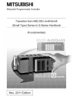
How the manual describes the explanation is shown below.
5.11 Renaming Data in a Project
A
QnA
FX
This table
indicates the
applicable items
for A series,
QnA series and
FX series.
[Purpose]
Renames the existing data in a project.
[Operating Procedure]
Select [Project]
[Edit data]
Items which
are set in the
section are
explained.
[Rename].
[Dialog Box]
1)
5)
2)
3)
The desired
window opens
by selecting
the items in the
specified order.
4)
[Description]
1) Data type
Designates the data type (program, common comment, comments
by program, device memory).
2) Data name before renaming
Designates the data name before renaming.
3) Renamed data name
Designates the new data name after renaming.
The data name must be designated in up to 8 characters.
4) Title
Displays the set title of the data.
If necessary, the title can be edited and stored.
It must be designated in up to 32 characters.
The dialog
boxes set in
the section
are explained.
The contents of
the items and
buttons are
explained.
The numbers
correspond to
those specified
in the window
shown under the
title of [Dialog box].
5) OK button
Click this button after making necessary settings.
POINT
This operation cannot change the data name of comments by
program to "COMMENT".
For changing the comments by program to the common
comment (COMMENT), refer to "Setting Comment Types"
(Section 9.6).
5 - 11
This gives the information related to the topic discussed and also the helpful information.
A - 14
A - 14
Symbols used in this manual, and the contents and examples of them are shown below.
1)
2)
3)
4)
No.
1)
Symbol
[
]
2)
3)
4)
Contents
Menu name of menu bar
Example
[Project]
Icon in toolbar
<<
>>
Tab name of dialog box
Command button in dialog box
<<Program common>>
lOKl button
The functions that cannot be operated on GX Developer are grayed (masked) and
cannot be selected. There are the following reasons why they are not selectable.
(1) The PLC CPU used does not have the functions
For example, when the A1SCPU is chosen as the PLC type, it does not have
the STEP-RUN function and therefore [Online] [Debug] [Debug] cannot be
selected.
To see if your PLC CPU has the operable functions, check the specifications in
the PLC CPU user's manual or the like.
(2) The functions cannot be selected because they cannot be used with the currently
operated function
For example, when the monitor screen is open, PLC type change, connection
setup, PLC data attribute change, data coupling, parameter check and all
parameter clear cannot be performed.
A - 15
A - 15
Abbreviations and Terms in This Manual
This manual uses the abbreviations and terms listed in the following table to discuss
the GX Developer Software Package and PLC module. In addition, the following
table lists the names of modules whose names must be indicated explicitly.
Abbreviation/Generic Term
Generic product name of the product types SWnD5C-GPPW-E, SWnD5C-GPPWEA, SWnD5C-GPPW-EV and SWnD5C-GPPW-EVA. (n denotes any of versions 0
to 7)
GX Developer
GX Developer Version n
(SWnD5C-GPPW-E)
GX Developer Version n
(SWnD5C-GPPW-E) or earlier
GX Developer Version n
(SWnD5C-GPPW-E) or later
GX Simulator
ACPU
QCPU (A mode)
QnACPU
QCPU (Q mode)
FXCPU
AnNCPU
AnACPU
AnUCPU
A series
QnA series
Q series
FX series
GPPA
GPPQ
MEDOC
FXGP(DOS)
FXGP(WIN)
SFC
Computer link
Module
For A series
Serial
communication
Module
For QnA
series
For AnU
For Q series
C24
QE71
E71
Q series-compatible E71
Ethernet board
CC-Link
PLC
A - 16
Description/Target Module
When limited to the major version (n denotes the version number)
When limited to earlier than the major version (n denotes the version number)
When limited to later than the major version (n denotes the version number)
Generic product name of the product types SWnD5C-LLT-E, SWnD5C-LLT-EA,
SWnD5C-LLT-EV and SWnD5C-LLT-EVA. (n denotes any of versions 0 to 6)
Generic term for PLC available with MELSEC-A
Including MOTION (SCPU)
(However, GX Developer does not support A1, A2, A3, A3H, A3M, A52G, A73,
A0J2 and A3V.)
Generic term for Q02(H)-A and Q06H-A
Generic term for PLC available with MELSEC-QnA
Generic term for Q00J, Q00, Q01, Q02(H), Q06H, Q12H, Q12PH, Q25H and
Q25PHCPU
Generic term for PLC available with MELSEC-F
(The target PLCs are FX0, FX0S, FX0N, FX1, FX, FX2, FX2C, FX1S, FX1N, FX2N
and FX2NC. )
A1NCPU, A2NCPU(S1), A3NCPU
A2ACPU(S1), A3A
A2UCPU(S1), A2USCPU(S1), A2ASCPU(S1), A2ASCPU-S30, A2ASCPU-S60,
A2USHCPU-S1, A3U, A4U
For GX Developer PLC type selection by ACPU
For GX Developer PLC type selection by QnACPU
For GX Developer PLC type selection by QCPU (Q mode)
For GX Developer PLC type selection by FXCPU
SW
SRXV-GPPA
IVD-GPPA
SW
SW
IVD-GPPQ
MELSEC-MEDOC
SW1PC-FXGPEE/AT
SW0PC-FXGP/WIN-E
Generic term for MELSAP2/MELSAP3/MELSAP-L
A1SJ71C24-R2, A1SJ71C24-R4, A1SJ71C24-PRF
A2CCPUC24(-PRF), A1SCPUC24-R2
AJ71UC24, A1SJ71UC24-R2, A1SJ71UC24-R4, A1SJ71UC24-PRF
Generic term for AJ71QC24, AJ71QC24-R2, AJ71QC24-R4, AJ71QC24N,
A1SJ71QC24, A1SJ71QC24-R2, AJ71QC24N-R2, AJ71QC24N-R4,
A1SJ71QC24N and A1SJ71QC24N-R2
Generic term for QJ71C24 and QJ71C24-R2
Computer link Module, Serial Communication Module
AJ71QE71(B5), A1SJ71QE71-B2, A1SJ71QE71-B5
AJ71AJ71E71-S3, A1SJ71E71-B2-S3, A1SJ71E71-B5-S3
A1SJ71E71-B2, A1SJ71E71-B5
Generic term for QJ71E71, QJ71E71-B2 and QJ71E71-100
Ethernet PC card, Ethernet I/F board
Control & Communication Link
PROGRAMMABLE LOGIC CONTROLLER
A - 16
Abbreviation/Generic Term
Personal computer
Actual program
Actual device
GSV
PC CPU module
A - 17
Description/Target Module
Personal computer compatible with Windows® 95/98/Me/2000 and
Windows NT® Workstation 4.0
A program created in the label program and compiled.
A program executable via the PLC CPU.
The term "actual device" is used in this manual to differentiate a program created
under a label name and one that has been compiled.
(A compiled program to which device has been assigned.)
Q173CPU/Q172CPU Programming SoftwareSW6RN-GSV13
Q173CPU/Q172CPU Programming SoftwareSW6RN-GSV22P
MELSEC-Q series compatible PC CPU module (CONTEC CO. LTD. make)
A - 17
1 GENERAL DESCRIPTION
MELSOFT
1. GENERAL DESCRIPTION
1
Product Outline and Features
Outline
This section explains GX Developer (unless otherwise specified, the product name represented GX
Developer will hereafter be its English version 7).
GX Developer is a software package having the following functions.
1. Program creation
2. Writing and reading to/from PLC
Writing
Reading
PLC
3. Monitoring (example: device batch monitoring)
The circuit monitor, device monitor, and device registration monitor can be used for monitoring.
4. Debugging
The created sequence program is written into PLC to test that the written sequence program
operates normally.
In addition, newly developed GX Simulator 1 (unless otherwise specified, the product name
represented GX Simulator will hereafter be its English version 6) can be used to debug the
program on a single personal computer.
PLC
PLC
5. Diagnostics PLC
The current error status, error status or error log can be displayed to shorten the time required
for error recovery.
Also, system monitoring (QCPU (Q mode) only) provides in-depth information on the special
functions. Therefore, if an error occurs, recovery work can be done in much shorter time.
: The GX Simulator is an independent function and may be purchased separately.
1-1
1-1
1 GENERAL DESCRIPTION
MELSOFT
Features
GX Developer has the following features.
1
1. Common software
GX Developer can create the data of the Q series, QnA series, A series (including the motion controller
(SCPU)) and FX series, with their setting operations common, and is abbreviated to GPPA. Note that this
does not apply to the A6GPP/A6PHP-compatible software package. Data can be converted into an
SW
-GPPQ GPP function software package (hereafter abbreviated to GPPQ) format file and edited on
GPPA or GPPW.
When the FX series is selected, data can be converted into a DOS version programming software
(hereafter abbreviated to FXGP(DOS)) or SW0PC-FXGP/WIN programming software (hereafter
abbreviated to FXGP(WIN)) format file and you can edit data on FXGP(DOS) or FXGP(WIN).
2. Advantages of Windows are utilized for dramatic improvements in operability
Comment data created on Excel, Word or the like can be copied or pasted for data diversion.
3. Standardized programs
(1) Label programming
By using label programming to create sequence programs, you can create standard programs with
labels without being conscious of device numbers.
The programs created by label programming can be compiled for use as an actual program.
(2) Function block (hereafter abbreviated to the FB)
The FB is a function developed to improve the efficiency of developing sequence programs. The
ladder blocks of a sequence program that are used repeatedly for sequence program development are
converted into components to facilitate sequence program development. Also, the conversion of
ladder blocks into components prevents sequence program inputting mistakes when they are utilized
for other sequence programs.
(3) Macros
By naming any ladder patterns (macro names) and registering them to a file (macro registration),
merely entering simple instructions allows the registered ladder patterns to be read and the devices to
be changed for data diversion.
4. Ease of setting access to another station
As the connection target can be specified graphically, you can set access to another station easily if a
complicated system has been configured.
5. Connection with PLC CPU in any of various methods
(1) Via serial port
(2) Via USB
(3) Via MELSECNET/10(H) board
(4) Via CC-Link board
(5) Via Ethernet board
(6) Via CPU board
(7) Via AF board
6. Fully useful debugging functions
(1) Use of the GX Simulator ensures much easier debugging.
(a) There is no need to make connection with the PLC CPU.
(b) There is no need to create a pseudo sequence program (debugging program).
(2) Containing the explanations of CPU errors and special relays/special registers, Help is useful when an
error has occurred online or when you want to know the contents of the special relays/special registers
during programming.
(3) If an error occurs during data creation, the corresponding message is displayed to indicate the cause
of that error, substantially reducing data creation time.
1-2
1-2
1 GENERAL DESCRIPTION
MELSOFT
1.1 Functions Lists
The GX Developer functions are listed below.
The functions are divided into normally common functions (project, online, diagnosis,
tool, window, help) and functions for objects to be edited and set (edit,
search/replacement, conversion, display).
In addition, there are executable and inexecutable functions depending on the CPU
series.
" " in the table indicates the function that is usable when GX Developer is installed
as monitoring-only GX Developer.
(1) List of common functions
Fixed functions independent of the type of the object being edited or set
Project (Common functions)
New project
Open project
Close project
Save
Save as
Delete project
Verify
Copy
Edit data
New
Copy
Delete
Rename
Change program type
Change PLC type
Import file
Import from GPPQ format file
Import from GPPA format file
Import from FXGP(WIN) format file
Import from FXGP(DOS) format file
Import from Melsec Medoc format file (Print out)
Import from Melsec Medoc format file
Export file
Export to GPPQ format file
Export to GPPA format file
Export to FXGP(WIN) format file
Export to FXGP(DOS) format file
Macro
Registration macros
Macro utilize
Delete macros
Macro reference path
Function Block
Diversion
Rename
Printer setup
Print
Start new GX Developer session
Exit GX Developer
Only for
monitoring
Refer To
Creates a new project.
Opens an existing project.
Closes an open project.
Saves the project.
Names and saves the project.
Deletes an existing project.
Verifys data between projects.
Copies data between projects.
4.1
4.2
4.3
4.4
4.5
4.6
4.7
4.8
Adds data to a project.
Copies data in a project.
Deletes data in a project.
Renames data in a project.
Change the program type in the project
Changes the PLC type.
4.9
4.10
4.11
4.12
4.13
4.14
Read a GPPQ file
Read a GPPA file
Read a FXGP(WIN) file
Read a FXGP(DOS) file
Import from Melsec Medoc format file
Import from Melsec Medoc format file
4.15.1
4.15.1
4.15.1
4.15.1
4.15.2
4.15.3
Write a GPPQ files
Write a GPPA files
Write a FXGP(WIN) files
Write a FXGP(DOS) files
4.16
4.16
4.16
4.16
Registration macros
Macro utilize
Delete macro instruction from the file
Set the macro instruction reference path
5.2.1
5.2.2
5.2.3
5.2.4
Diversion FB on ladder program.
Rename the FB
Changes the printer settings.
Prints data.
Restarts GX Developer.
Exits GX Developer.
14.1
14
4.17
4.18
(To the next page)
1-3
1-3
1 GENERAL DESCRIPTION
MELSOFT
(Continued from the previous page)
Online (Common functions)
Transfer setup
Read from PLC
Write to PLC
Verify with PLC
Write to PLC (Flash ROM)
Write the program memory to ROM
Write to PLC (Flash ROM)
Delete PLC data
Change PLC data attributes
PLC user data
Read PLC user data
Write PLC user data
Delete PLC user data
Monitor
Monitor mode
Monitor (Write mode)
Start monitor (All windows)
Stop monitor (All windows)
Start monitor
Stop monitor
Change current value monitor (Decimal)
Change current value monitor (Hexadecimal)
Device batch
Entry data monitor
Buffer memory batch
Monitor condition setup
Monitor stop condition setup
Program monitor list
Interrupt program monitor list
Scan time measurement
Entry ladder monitor
Delete all entry ladder
Debug (ladder)
Device test
Forced input output registration/cancellation
Debug
Skip execution
Partial execution
Step execution
Designates a PLC destination from GX
Developer.
Reads data from PLC.
Writes data to PLC.
Verifys data with PLC data.
Writes program memory data to the
standard ROM/IC memory card (ROM).
Writes data to the standard ROM/IC
memory card (ROM).
Deletes PLC data.
Changes PLC data attributes.
Reads user data from the PLC.
Writes user data to the PLC.
Deletes user data of the PLC.
Places the circle edit screen in monitor
mode.
Sets the circuit (monitor write) mode.
Starts monitoring all open windows.
Stops monitoring all open windows.
Restarts the stopped monitor.
Stops the monitor.
Displays the current device value of the
circuit monitor in decimal form.
Displays the current device value of the
circuit monitor in hexadecimal form.
Monitors devices in batch mode.
Entry data mode
Monitors the buffer memory in batch
mode.
Sets the monitor execusion conditions.
Sets the monitor stop conditions.
Monitors a program list.
Lists the interrupt programs.
Measures the scan time.
Entry the ladder block
Delete all entry ladder
Only for
monitoring
Refer To
16.1
16.3
16.3
16.4
16.5.1
16.5.2
16.6
16.7
16.8.1
16.8.2
16.8.1
17.1
17.3
17.2
17.2
17.1
17.1
17.4
17.4
17.5
17.6
17.5
17.7
17.7
17.8
17.9
17.10
17.12
17.13
Turns on or off the device or changes the
vallue.
This will register the forced input output of
device X/Y
Executes/disables the debugging function.
Makes settings for skip.
Makes settings for partial operation.
Makes settings for step execution.
18
18.5
18.3
18.4
Execute sampling trace.
Operates the PLC remotely.
18.11
18.6
18.1
18.2
Trace
Sampling trace
Remote operation
(To the next page)
1-4
1-4
1 GENERAL DESCRIPTION
MELSOFT
(Continued from the previous page)
Only for
monitoring
Online (Common functions)
Keyword/Password (Q series)
Register keyword
Delete keyword
Disable keyword
Clear PLC memory
Format PLC memory
Arrange PLC memory
Set clock
Registers or changes the keyword.
Cancels the keyword.
Unlocks access by keywords
Clears the PLC memory cassette or device memory.
Formats the PLC memory.
Arranges the data area within the PLC memory.
Sets the internal timer of the PLC.
19
19
19
20.1
20.2
20.3
20.4
Diagnosis (Common functions)
PLC Diagnostics
Network diagnostics
Ethernet diagnostics
CC-Link / CC-Link/LT diagnostics
System monitor
Online module change
Refer To
Diagnoses the PLC.
Diagnoses the network
Diagnoses Ethernet.
Diagnostics the CC-Link or CC-Link/LT
Monitors the system status of the PLC.
Changes module during online.
21.1
21.2
21.4
21.3
21.5
21.6
Tool (Common functions)
Check program
Marge data
Check parameter
Transfer ROM
Read
Write
Compare
Write to file
Delete unused comments
Clear all parameters
IC memory card
Read IC memory card
Write IC memory card
Start ladder logic test
Set TEL data
Connection
Disconnect
TEL data
AT command
Call book
Intelligent function utility
Utility list
Session
Customize keys
Change display color
Options
Create start-up settings file
Starting CC-Link Configurator
Refer To
Checks the program.
Links data.
Checks the parameter.
15.1
15.2
15.3
Reads data from ROM.
Writes data to ROM.
Compares data with ROM data.
Writes ROM data to files.
Delete the comments which isn't used at program
Deletes parameters.
15.8.1
15.8.1
15.8.1
15.8.2
15.9
15.4
Reads data from the IC memory card.
Writes data to the IC memory card.
Starts the ladder logic test.
1
Connect the line for A6TEL/Q6TEL
Disconnect the line
Set the report data of A6TEL or Q6TEL
Entry the modem
Set the call book
Shows the utility names required to edit the
intelligent function unit parameters.
Starts the intelligent function utility.
Changes key assignments for circuit symbol input.
The display color is changed
Sets the options.
Creates a file to save initial settings of the project.
Special relay/register
Key operation list
Product information
Connect to MELFANSweb
Displays the description of each CPU error code.
Displays the description of special relays or
registers.
Displays the description of each key operation.
Displays product information (such as version
number).
Connect to MELFANSweb
15.7
15.7
15.9
15.10
15.11
15.13
15.16
Refer To
Cascades windows.
Tiles the windows vertically.
Tiles the windows horizontally.
Arranges the icons in the lower part of the window.
Close all open windows.
Help (Common functions)
CPU error
15.5.1
15.5.2
15.14
22.4
22.4.3
22.3.3
22.3.2
22.3.1
Window (Common functions)
Cascade
Tile vertically
Tile holizontally
Arrange icons
Close all Windows
Refer To
15.12
15.12
15.12
15.12
15.12
Refer To
15.15
15.15
15.15
15.15
15.15
1: Disabled for Use Label + FB.
1-5
1-5
1 GENERAL DESCRIPTION
MELSOFT
(2) Ladder editing function list
The following functions can be performed to edit the ladders and operation
outputs/transition conditions.
Only for
monitoring
Edit (Ladder editing functions)
Undo
Cut
Copy
Paste
Insert line
Delete line
Insert row
Delete row
Insert NOP batch
Delete NOP batch
Draw line
Delete line
Change TC setting
Read mode
Write mode
Ladder symbol
Refer To
Reverses the last operation.
Moves the selected data to the Clipboard.
Copies the selected data to the Clipboard.
Pastes the contents of the Clipboard at the cursor
position.
Inserts a row at the cursor position.
Deletes a row at the cursor position.
Inserts a column at the cursor position.
Deletes a column at the cursor position.
Inserts NOP before a circuit block at the cursor
position.
Deletes all NOPs in the program at a time.
Inserts a line.
Deletes a line.
Changes the setting value of the timer or counter.
Places the circuit screen in the read mode.
Places the circuit screen in write mode.
2
2
6.2.9
3.3.1
3.3.2
2
3.3.1
6.2.5
6.2.5
6.2.5
6.2.5
6.2.6
6.2.7
6.2.2
6.2.4
6.3
6
6
Open contact
Inserts
at the cursor position.
3
6.2
Close project contact
Inserts
at the cursor position.
3
6.2
Open branch
Inserts
at the cursor position.
3
6.2
Close project branch
Inserts
at the cursor position.
3
6.2
Coil
Inserts
at the cursor position.
3
6.2
Application instruction
Inserts
at the cursor position.
3
6.2
Vertical line
Inserts
at the cursor position.
6.2
Horizontal line
Inserts
at the cursor position.
6.2
Delete vertical line
Inserts
at the cursor position.
6.2
Delete Horizontal line
Inserts
at the cursor position.
6.2
Rising pulse
Inserts
at the cursor position.
3
6.2
Falling pulse
Inserts
at the cursor position.
3
6.2
Rising pulse Open branch
Inserts
at the cursor position.
3
6.2
Falling pulse Close branch
Inserts
at the cursor position.
3
6.2
Invert operation results
Inserts
at the cursor position.
3
6.2
Convert operation results to rising pulse
Inserts
at the cursor position.
3
6.2
Convert operation results to falling pulse
Inserts
at the cursor position.
3
6.2
Documentation
Comment
Statement
Note
Statement/Note block edit
Edits the comment at the cursor position.
Edits the statement in the ladder at the cursor
position.
Edits the note in the ladder at the cursor position.
The statement and note under the program is
edited by the batch.
9.4.4
10.3.1(1)
10.4.1(1)
10.5
2: Enabled for ladder registration monitoring.
3: Enabled as a search function.
1-6
1-6
1 GENERAL DESCRIPTION
MELSOFT
Search/Replacement (Ladder editing functions)
Find device
Find instruction
Find step No.
Only for
monitoring
Searches for a device.
Searches for an instruction.
Searches for a step number.
Searches for a character string in comment, note, or
statement.
Find contact or coil
Finding data
Searches for and replaces a device.
Searches for and replaces an instruction.
Searches for and replaces a contact a with a contact
b.
Searches for and replaces a character string in
comment, note, or statement.
This will exchange the starting address of the buffer
memory access instruction
Searches for and replaces the type of a character
string between statement and note.
Replacing data
Finds whether the device is being used by a contact
or coil.
Finds where the device is used.
Find character string
Find contact or coil
Finding data
Replace device
Replace instruction
Change open/close contact
Replace character string
Chang module start address
Replace statement/note type
Replacing data
Cross referense list
List of used devices
6.4.1
6.4.2
6.4.3
6.4.4
6.4.5
6.4.6
6.4.7
6.4.8
6.4.9
6.4.10
6.4.11
6.4.12
6.4.13
6.4.14
6.4.15
Conversion (Ladder editing functions)
Convert
Convert (All programs being edited)
Convert block (Online change)
Refer To
Converts the program.
Converts the programs (not converted yet) in all
windows.
Converts the program and writes it during run.
8.1
8.2
16.9
Display (Ladder editing functions)
Comment
Statement
Note
Device Label
Macro instruction format display
Comment format
4 × 8 characters
3 × 5 characters
Alias display format
Displayed instead of device
Displayed with device
Toolbar
Status bar
Zoom
50%
75%
100%
150%
Auto
Project data list
Instruction list
Elapsed time
Refer To
Refer To
Displays or hides comments.
Displays or hides statements.
Displays or hides notes.
Displays or hides device names.
Provides display in the user macro instruction
format.
3.8
3.9
3.10
3.11
Shows comments in 4 × 8 or 2 × 8 characters.
Shows comments in 3 × 5 characters.
3.12
3.12
5.16
Displays the machine name at the device name
display position.
Arrange and displays the machine name above the
device name.
Displays of hides the toolbar.
Displays of hides the status bar.
3.13.1
3.13.2
3.4
3.5
Displays a circuit reduced to 50%.
Displays a circuit reduced to 75%.
Displays a full-size circuit.
Displays a circuit magnified to 150%.
Displays a circuit according to the screen size.
Displays or hides the project data list.
Switches program circuit display and list display.
Displays the elapsed time.
3.6
3.6
3.6
3.6
3.6
3.7
6
22.4.1
(3) Device comment editing function list
The following functions can be performed to edit device comments.
Edit
Clear all (all devices)
Clear all (displayed devices)
Setup comment
Setup comment range
1-7
Deletes the comments or device names of all
devices.
Deletes the displayed comments or device names.
Sets the common comments or comments by
program.
Sets a comment range.
Only for
monitoring
Refer To
9.5.1
9.5.2
9.6
9.7
1-7
1 GENERAL DESCRIPTION
MELSOFT
(4) Device memory setting function list
The following functions can be performed to set the device memory.
Only for
monitoring
Edit
Clear all (all devices)
Clear all (displayed devices)
FULL
Deletes data of all devices.
Deletes the data of displayed devices.
Sets all data to the specified value.
Refer To
11.3.1
11.3.2
11.4
(5) Label programming function list
The following functions are available for label program editing.
Editing (Functions for label program editing)
Auto device setting
Global variable setting
Local variable setting
Setting auto device
Setting global variable
Setting local variable
Editing (Functions for local label variable/global label variable editing)
Insert line
Add line
Delete line
Delete auto External
Delete all
Auto device setting
Global variable setting
Inserts a line at the cursor position
Adds a line under the cursor position
Delete a line from the cursor position
Delete all Auto External
Delete all variables
Setting auto device
Setting global variable
Import the device comment (local label
variables only)
Export the device comment
Import the device comment
Export the device comment
Display (Functions for label program editing)
Display device program
Switches the display/non-display of the
device display screen.
Device program display mode
Below
Display the zoom or the device screen at
below
Display the zoom or the device screen at
right
Display step synchronization between
label program and device program
Right
Display step synchronization
Conversion (Functions for label program editing)
Compile
Compile (All programs being edited)
Compile the label program
Compile the all the not compiled label
programs
Compile the all label programs
Set compile option
Compile (All programs)
Compile option
Tool
1-8
Refer To
5.1.4
5.1.3
5.1.3
Refer To
5.1.3
5.1.3
5.1.3
5.1.5
5.1.6
5.1.4
5.1.3
5.1.7
5.1.8
Refer To
5.1.10
5.1.10
5.1.10
5.1.10
Refer To
5.1.9
5.1.9
5.1.9
Refer To
Sort
Label order
Device/Constant order
Device type order
Only for
monitoring
Sort by label
Sort by Device/Constant
Sort by Device type
5.1.3
5.1.3
5.1.3
5.1.3
1-8
1 GENERAL DESCRIPTION
MELSOFT
(6) SFC editing function list
The following functions can be performed to edit SFC.
For details, refer to the GX Developer Version6 operating manual (SFC
manual).
Only for
monitoring
Edit (SFC editing functions)
Insert line
Delete line
Insert row
Delete row
Edit the line
Inserts a row at the cursor position.
Deletes a row at the cursor position.
Inserts a column at the cursor position.
Deletes a column at the cursor position.
Vertical line
Selection divergence
Simultaneous divergence
Selection convergence
Simultaneous convergence
Delete the line
Change TC setting
Read mode
Write mode
Step attribute
Normal
Stored coil
Stored operation (without transition check)
Stored operation (with transition check)
Reset
Writes a vertical line.
Writes selective branch.
Write a parallel branch.
Writs a selective coupling.
Writes a parallel coupling.
Deletes the selective/parallel branch or selective/parallel
coupling.
Changes the setting value of the timer or counter.
Places the circuit screen in the read mode.
Places the circuit screen in write mode.
Set the normal
Set the stored coil (SC) type
Stored operation (without transition check) [SE] type
Set the stored operation (with transition check) [ST] type
Set the reset [R] type
Edit (SFC editing functions)
SFC symbol
Step
Inserts
at the cursor position.
Block START step (with END check)
Inserts
at the cursor position.
Block START step (without END check)
Inserts
at the cursor position.
Jump
Inserts
at the cursor position.
End step
Inserts
at the cursor position.
Dummy step
Inserts
at the cursor position.
Transition
Inserts
at the cursor position.
Selection divergence
Inserts
at the cursor position.
Simultaneous divergence
Inserts
at the cursor position.
Selection convergence
Inserts
at the cursor position.
Simultaneous convergence
Inserts
at the cursor position.
Vertical line
Inserts
at the cursor position.
Documentation
Comment
Block information
Edit comment
Set the block information
Search/Replacement (SFC editing functions)
Find device
Find instruction
Find step No./block No.
Find character string
Replace device
Replace instruction
Change open/close contact
Replace step No.
Replace character string
Cross reference list
List of used devices
Finds device.
Finds instruction.
Finds the step number.
Finds character string.
Replaces a device.
Replaces an instruction.
Replaces open/close contact.
Replace the step number
Replaces a character string.
Finds whether the device is being used by a contact or
coil.
Finds where the device is used.
(To the next page)
1-9
1-9
1 GENERAL DESCRIPTION
MELSOFT
(Continued from the previous page)
Conversion (SFC editing functions)
Convert (All programs being edited)
Convert (block)
Convert block (all block)
Display convert error
Only for
monitoring
Converts the programs (not converted yet) in all
windows.
Convert the block data
Convert the all block
Display the convert error
Display (SFC editing functions)
Display comment of step and TR
Display label of step and TR
Row of SFC
Zoom setting
Below
Right
Split
Set the contact at right
5 contacts, 11 contacts
9 contacts, 11 contacts
Review SFC
Display block list
MELSAP-L format
Display the reference window
Displays the step and transition comment.
Displays the step and transition label.
Set the row number of SFC diagram.
Display the zoom ladder of list at below
Display the zoom ladder of list at right
Display the zoom ladder of list
You can select "5 contacts" or "9 contacts" when "Right"
is specified for Zoom partition.
You can select "9 contacts" or "11 contacts" when
"Bellow" is specified for Zoom partition.
Review SFC
Display block list
Change the SFC view format
Display the reference window
Online (Common functions)
Debug (SFC)
Device test
Block brake
Step brake
Block run
Step run
1 step run
Block forced stopping
Step forced stopping
Reset stored step
Run all block
1 - 10
Sets the device value.
Block brake
Step brake
Block run
Step run
1 step run
Block forced stopping
Step forced stopping
Reset stored step
Run All Block
1 - 10
1 GENERAL DESCRIPTION
MELSOFT
1.2 FX Series Programming
This section describes the main differences between the GX Developer operating
®
environment and FX-dedicated programming software (DOS version, Windows®
version) operating environment and the points to be noted.
Target PLC:
FX0, FX0S, FX0N, FX1, FX2, FX2C, FX1S, FX1N, FX2N, and FX2NC series
In the selection of PLC type, select FXU/FX2C for FX,FX2 and FX2C
See Section 2 for details on the system configuration and connection method.
Operating Environment
• Differences of main terms
⋅ Program file handling
GX Developer programming data is created in units of folders (directories) called
the projects.
FXGP(DOS) and FXGP(WIN) do not have the concept of project, and program
files are created in any folders (directories) for management.
For this reason, the program file names in FXGP(DOS) and FXGP(WIN) are
project names in GX Developer.
For details on project specification, see Section 3.2.
⋅ Comments
(1) The number of characters that can be input may be different (see Appendix
11).
(2) The circuit comment is called the statement.
(3) The coil comment is called the note.
⋅ Parameter settings
Some setup screens have different names (see Section 13).
• Differences in operations
⋅ Step ladder instructions (STL, RET) are displayed in different ways (see Section
6.1.2).
⋅ Monitor display may be partially different (see Appendix 11).
⋅ Application instructions using the FNC. No. are not available.
⋅ Although FX PLC operates in the sequence program with no End instructions,
END instructions are forceful input in GX Developer.
1 - 11
1 - 11
1 GENERAL DESCRIPTION
MELSOFT
• Common items and others
⋅ Items that are available for only A series or QnA series are disabled and
displayed in gray in the GX Developer operation screens.
⋅ Partial execution, step run, and step run debug functions cannot be used when
FXCPU is connected. However, these debug functions can be used for
debugging with a single personal computer when the GX Simulalor is connected
(see Chapter 18 for details).
⋅ The program conversion function is provided for conversion from A to FX series
and vice versa (see Section 4.13 and Appendix 4 for details).
⋅ The GX Developer FX series allows users to create only one program file.
Because A series or QnA series allows users to create multiple program files,
this manual may use screen examples including multiple program files when
describing the function. However, when FX series is selected, only the main
program is displayed on the screen.
⋅ The connection cable and RS-232/RS-422 converter for FX PLC may be
different from those for A or QnA series PLC (see Subsection 2 for details).
⋅ GX Developer is cable of reading from or writing to FXGP(DOS) and
FXGP(WIN) files basically. However, note that there are some exceptions (see
Sections 4.14 and 4.15 and Chapter 9 for details).
⋅ SFC program of FX series is displayed as STL and RET instructions on the
circuit edit screen of the GX Developer since the program is described as the
step ladder instructions.
It is possible to edit on the circuit.
1 - 12
1 - 12
1 GENERAL DESCRIPTION
MELSOFT
1.3 Basic Key Specifications
The following table summarizes the purposes of the keys used with the GX
Developer.
Key Name
Purpose
Escl
Closes the window, interrupts execution, and selects instructions.
Tabl
Enters a tab code and switches the target to which the cursor must be moved quickly.
Ctrl + Tabl
Ctrll
Used in a combination with a alphanumeric key or a function key.
Shiftl
Selects a character at the Shift position.
Caps Lockl
Altl
Back spacel
Enterl
Page Upl
Page Downl
Switches upper-case and lower-case letters.
Selects the menu.
Deletes a character to the left of the cursor position.
Enters a carriage return.
Scrolls down the circuit or list by page. (Scrolls a screen in minus direction.)
Scrolls up the circuit or list by page. (Scrolls a screen in plus direction.)
Insertl
Enters a space character at the cursor position.
Deletel
Deletes a character at the cursor position. (Clears all settings.)
Homel
Moves the cursor to the home position.
Moves the cursor or scrolls the circuit or list in unit of lines. (
Ctrl + Homel
Ctrl + Endl
Moves the cursor to the End instruction in the circuit mode.
Scroll Lockl
Inhibits scroll-up and scroll-down.
Num Lockl
Uses the Ten-key pad for numeric key input only.
1 - 13
)
Moves circuit the cursor to step 0 in the mode.
1 - 13
2 SYSTEM CONFIGURATION
MELSOFT
2. SYSTEM CONFIGURATION
2.1 Connection from the Serial Port
The following system configuration is made up by connection from the serial port.
1
USB cable
USB communication
QCPU (Q mode)
2
QC30R2
QCPU (Q mode)
QCPU (A mode)
3
Converter/cable
Serial port communication
ACPU
QnACPU
3
Converter/cable
5
Computer link
FXCPU
See Appendix-3
RS-232
C24
CC-Link (via G4)
GX Developer
(SW7D5C-GPPW-E)
3
Converter/cable
CC-Link
G4 module
G4-S3 module
MELSECNET(II)
ACPU
QnACPU
QCPU (Q mode)
QCPU (A mode)
ACPU
QnACPU
QCPU (Q mode)
QCPU (A mode)
3
Converter/cable
Remote station
Remote unit
Master station
Remote station
Remote unit
Control station
MELSECNET/10
MELSECNET/H
Via modem
3
Converter/cable
4
Cable supplied with modem
Modem
ACPU
QnACPU
A6TEL/Q6TEL
Modem
QnACPU
4
Cable supplied with modem
C24
QCPU (Q mode)
QCPU (A mode)
FX2N series
2-1
2-1
2
2 SYSTEM CONFIGURATION
MELSOFT
1: About the USB cable (QCPU (Q mode) compatible)
®
(1) Usable with Windows 98/Me/2000 when the USB driver has been
installed.
®
®
(2) Unusable for Windows 95,Windows NT Workstation 4.0.
(3) Use of the USB cable allows only one PLC CPU to be connected.
(4) Use the USB cable which conforms to the USB Standard Rev. 1.1.
(5) Refer to POINT in Section 16.1 for precautions for and restrictions on using
the USB cable to make communications.
2
2: About the cable (QCPU (Q mode), QCPU (A mode) compatible)
For communication in 115.2/57.6kbps
Fast communication cannot be made if the Personal computer used is not
compatible with the communication speed of 115.2/57.6kbps.
If a communication error occurs, reduce the baud rate setting and restart
communication.
The following cable has been confirmed by Mitsubishi Electric that it will work
properly.
Using the cable of Mitsubishi Electric make
RS-232 cable
QC30R2 (when Personal computer connector is D-sub, 9-pin)
3: About the converter/cable (ACPU, QnACPU, FXCPU compatible)
(1) Using the products of Mitsubishi Electric make
Personal computer Side
(RS-232 cable)
RS-232/RS-422
Converter
PLC CPU Side
(RS-422 cable)
For ACPU, QnACPU, FX1/FX2CPU/FX2CCPU
FX-422CAB (0.3m)
F2-232CAB-1
(when Personal computer
connector is D-sub, 9-pin)
FX-422CAB-150 (1.5m)
FX-232AW(C)
For FX0/FX0S/FX0N/FX1S/FX1N/FX2N/FX2NCCPU
FX-422CABO (1.5m)
2-2
2-2
2 SYSTEM CONFIGURATION
MELSOFT
• How to identify compatibility of the F2-232CAB and F2-232CAB-1 cables with the
ACPU and QnACPU
Check the indication of the model label attached to the cable.
Incompatible products
Compatible products (with indication of F/FX/A)
F2-232CAB
Y990C
F2-232CAB(F/FX/A)
Y990C
F2-232CAB-1
Y990C
F2-232CAB-1(F/FX/A)
Y990C
4: About the modems relayed
Use the straight cables supplied with the modems.
5: About computer link
When the A series is used for communication via the C24/UC24, the program
which uses V, Z (index qualification) cannot be monitored.
2-3
2-3
2 SYSTEM CONFIGURATION
MELSOFT
2.2 Connection from the Interface Boards
The following system configuration is made up by connection from the interface
boards.
Refer to the corresponding board manuals for the way to connect the boards and
install the drivers.
1
MELSECNET/10 board
A70BDE-J71QLP23
(Optical loop)
A70BDE-J71QLP23GE
(Optical loop)
A70BDE-J71QBR13
(Coaxial bus)
A70BDE-J71QLR23
(Coaxial loop)
ACPU
QnACPU
QCPU (Q mode)
QCPU (A mode)
Driver
SW3DNF-MNET10
Other station PLC
MELSECNET/H board
GX Developer
(SW7D5C-GPPW-E)
Q80BD-J71BR11
(Coaxial bus)
Q80BD-J71LP21-25
(Optical loop)
Q80BD-J71LP21G
(Optical loop)
Q80BD-J71LP21GE
(Optical loop)
ACPU
QnACPU
QCPU (Q mode)
QCPU (A mode)
Driver
SW0DNC-MNETH-B
Other station PLC
2
CC-Link board
ACPU
QnACPU
QCPU (Q mode)
QCPU (A mode)
Driver
A80BDE-J61BT13
A80BDE-J61BT11
3
Ethernet board
Commercially available
Ethernet board
SW4DNF-CCLINK-B
Other station PLC
ACPU
QnACPU
QCPU (Q mode)
QCPU (A mode)
Driver
Driver supplied with
commercially available
Ethernet board
Other station PLC
CPU board
Driver
SW1DNF-ANU-B
A80BDE-A2USH-S1
1: MELSECNET/10 board
The following table indicates the drivers that cannot be used with the specific
Operating Systems.
Driver Name
SW3DNF-MNET10
Operating Systems
®
Cannot be used with Windows Me/2000.
If a communications error takes place, an error code is indicated in the least
significant 4 digits.
Refer to the error code list of the MELSECNET/10 board manual.
2-4
2-4
2 SYSTEM CONFIGURATION
MELSOFT
2: MELSECNET/H board
The following table indicates the drivers that cannot be used with the specific
Operating Systems.
Driver Name
SW0DNC-MNETH-B
Operating Systems
®
Cannot be used with Windows Me.
If the project has been started after selection of the Q12PH or Q25PHCPU,
connection via the MELSECNET/H board cannot be made.
3: CC-Link board
(1) The A80BDE-J61BT11 allows the master/local station to be set.
(2) Accessible only when the CC-Link board is set as the local station.
(3) If the project has been started after selection of the Q12PH or Q25PHCPU,
connection via the CC-Link board cannot be made.
4: Ethernet board
(1) The following Ethernet boards/cards have been confirmed by Mitsubishi
Electric to operate properly.
Maker Name
3COM make
Ethernet board/card
Allied Telesis make
TDK make
Ethernet board
2-5
Allied Telesis make
Model
Ethernet Link III LAN PC Card
Center COM LA-PCM Ethernet PC Card
LAN Adapter
10BASE-T LAN card
(Model: LAN-CD021BX)
RE2000 (ISA)
2-5
2 SYSTEM CONFIGURATION
MELSOFT
2.3 Connection from GX Developer Installed in PC CPU Module
(1) The following is the system configuration that can be connected from GX
Developer installed in the PC CPU module.
See 2.1
USB cable
USB communication
Serial port communication
Computer link
QCPU (Q mode)
See 2.1
QC30R2
QCPU (Q mode)
QCPU (A mode)
See Appendix-5
RS-232
C24
GX Developer
(SW7D5C-GPPW-E)
CC-Link
MELSECNET/H
Ethernet
Driver
PPC-DRV-01
CC-Link
Driver
PPC-DRV-01
MELSECNET/H
ACPU
QnACPU
QCPU (Q mode)
QCPU (A mode)
QCPU (Q mode)
QCPU (Q mode)
QCPU (Q mode)
Q Sries Bus
Multiple CPU
2-6
2-6
2 SYSTEM CONFIGURATION
MELSOFT
2.4 System Equipment Lists
(1) The following list indicates module connectable from the serial port.
PLC Series
Module Name
MELSECNET(II) data link remote I/O module
MELSECNET/B data link remote I/O module
MELSECNET/10 network remote I/O module
G4 module
PLC CPU module
Module Model
Q02(H), Q06H, Q12H, Q12PH, Q25H, Q25PH
Q02(H)-A, Q06H-A
QJ71C24, QJ71C24-R2
QJ72LP25, QJ72BR15
AJ65BT-G4-S3
Q2A, Q2AS(H), Q2AS1, Q2AS(H)S1, Q3A, Q4A, Q4AR
AJ71QC24, AJ71QC24-R2, AJ71QC24-R4,
AJ71QC24N, A1SJ71QC24, A1SJ71QC24-R2,
AJ71QC24N-R2, AJ71QC24N-R4, A1SJ71QC24N,
A1SJ71QC24N-R2
AJ72QLP25, AJ72QBR15, A1SJ72QLP25,
A1SJ72QBR15, QJ72LP25, QJ72BR15
AJ65BT-G4, AJ65BT-G4-S3
A0J2H, A1S(S1), A1FX, A1SJ, A1SH, A1SJH, A1N,
A2C, A2CJ, A2N(S1), A2S(S1), A2SH(S1), A3N,
A2A(S1), A3A, A2U(S1), A2US(S1), A2AS(S1), A2ASS30, A2AS-S60, A2USH-S1, A3U, A4U
AJ71UC24, A1SJ71UC24-R2, A1SJ71UC24-PRF,
A1SJ71C24-R2, A1SJ71C24-PRF, A1SCPUC24-R2,
A2CCPUC24, A2CCPUC24-PRF
AJ72P25, AJ72R25
AJ72T25B, A1SJ72T25B
AJ72LP25, AJ72LP25, AJ72BR15
AJ65BT-G4, AJ65BT-G4-S3
FX0(S), FX0N, FX1, FX2(C), FX1S, FX1N, FX2N(C)
PLC CPU module
A171SH, A172SH, A173UH(S1), A273UH(S3)
PLC CPU module
Q series
Serial communication module 1
MELSECNET/H network remote I/O module
G4-S3 module
PLC CPU module
Serial communication module 2
QnA series
MELSECNET/10 network remote I/O
module
G4 module
PLC CPU module
A series
FX series
MOTION
(SCPU)
Computer link module 3
(2) The following table indicates the modules which can be connected from the
MELSECNET/10 or MELSECNET/H (MELSECNET/10 mode) board.
PLC Series
Q series
QnA series
A series
Module Name
QJ71LP21, QJ71BR11
QJ71LP21, QJ71BR11, QJ71LP21-25
AJ71QLP21, AJ71QBR11, A1SJ71QLP21, A1SJ71QBR11
AJ71LP21, AJ71BR11, A1SJ71LP21, A1SJ71BR11
(3) The following table indicates the modules which can be connected from the
MELSECNET/H board.
PLC Series
Q series
Module Name
QJ71LP21, QJ71BR11, QJ71LP21-25
(4) The following list indicates modules connectable from the CC-Link board.
Module Name
Q series
QnA series
A series
QJ61BT11
AJ61QBT11, A1SJ61QBT11
AJ61BT11, A1SJ61BT11
(5) The following list indicates modules connectable from the Ethernet board.
Module Name
Q series
QnA series
A series
2-7
QJ71E71, QJ71E71-B2, QJ71E71-100
AJ71QE71, AJ71QE71-B5, A1SJ71QE71-B2, A1SJ71QE71-B5
AJ71E71-S3, A1SJ71E71-B2-S3, A1SJ71E71-B5-S3, A1SJ71E71-B2, A1SJ71E71-B5
2-7
2 SYSTEM CONFIGURATION
MELSOFT
1: The following table indicates whether the interfaces may be connected to
the personal computer when the PLC CPU is accessed from the personal
computer via the serial communication module (Q series).
If the module cannot be connected directly with the personal computer, it
may be usable as the "n"th module of multidropping.
Type
QJ71C24
QJ71C24-R2
Interface
1:1
Connection
Multidropping
First module
"n"th module
RS-232
RS-422/485
RS-232
RS-232
2: The following table indicates whether the interfaces may be connected to
the personal computer when the PLC CPU is accessed from the personal
computer via the serial communication module (QC24).
If the module cannot be connected directly with the personal computer, it
may be usable as the "n"th module of multidropping.
Type
AJ71QC24
AJ71QC24N
AJ71QC24-R2
AJ71QC24N-R2
AJ71QC24-R4
AJ71QC24N-R4
A1SJ71QC24
A1SJ71QC24N
A1SJ71QC24-R2
A1SJ71QC24NR2
2-8
Interface
1:1
Connection
Multidropping
First module
"n"th module
RS-232
RS-422/485
RS-232
RS-422/485
RS-232
RS-232
RS-232
RS-232
RS-422
RS-422/485
RS-422
RS-422/485
RS-232
RS-422/485
RS-232
RS-422/485
RS-232
RS-232
RS-232
RS-232
2-8
2 SYSTEM CONFIGURATION
MELSOFT
3: About the computer link module
Note that when the PLC CPU is accessed from the personal computer via
the computer link module, the modules that may be connected directly with
the personal computer are limited.
If the module cannot be connected directly with the personal computer, it
may be usable as the "n"th module of 1:n connection.
Type
AJ71UC24
AJ71C24-S6
AJ71C24-S8
Interface
1:1
Connection
1:n Connection
First module
"n"th module
RS-232
RS-422/485
RS-232
RS-422
RS-232
RS-422
A1SJ71UC24-R2
RS-232
A1SJ71C24-R2
RS-232
A1SJ71UC24PRF
RS-232
A1SJ71C24-PRF
RS-232
A1SJ71UC24-R4
RS-422/485
A1SJ71C24-R4
RS-422/485
A1SCPUC24-R2
RS-232
RS-232
A2CCPUC24
RS-422
RS-422/485
RS-232
A2CCPUUC24PRF
RS-422
RS-422/485
2-9
2-9
2 SYSTEM CONFIGURATION
MELSOFT
2.5 Precautions for Handling Projects on the Earlier Versions
2.5.1 Using GX Developer Version 4 (SW4D5C-GPPW-E) or earlier to handle project
The following are the precautions for using GX Developer Version4 (SW4D5CGPPW) or earlier to handle the project that has been created with GX Developer
Version7 (SW7D5C-GPPW-E).
Handle the project after reading the following precautions.
About device memory:
1. When editing on GX Developer (SW7D5C-GPPW-E) and the version of GX
Developer (SW4D5C-GPPW-E or earlier), do not create multiple device
memories.
(Refer to Chapter 11 for device memories.)
Do not read the GX Developer (SW7D5C-GPPW-E) created multiple device
memories on the version of GX Developer (SW4D5C-GPPW-E or earlier). The
data cannot be read correctly.
2. Do not read the GX Developer (SW7D5C-GPPW-E) created device memory of
32 MB or more on the version of GX Developer (SW4D5C-GPPW-E or earlier).
2 - 10
2 - 10
2 SYSTEM CONFIGURATION
MELSOFT
2.5.2 Using GX Developer Version 5 (SW5D5C-GPPW-E) or earlier to handle project
The following are the precautions for using GX Developer Version5 (SW5D5CGPPW-E) or earlier to handle the project that has been created with GX Developer
Version7 (SW7D5C-GPPW-E).
Handle the project after reading the following precautions.
1. About the parameters (for the Q02(H), Q06H, Q12H, Q25HCPU)
GX Developer Version5 (SW5D5C-GPPW-E) or earlier cannot handle the data
where the parameters of the following items have been set.
The following dialog box appears if the project saved in the personal computer
is read or read from PLC is performed from the PLC CPU.
[Items which cannot be read if set on GX Developer (SW7D5C-GPPW-E)]
• Multi PLC setting
• I/O assignment (when multi PLC setting has been made)
• Memory card of boot file setting Standard ROM all data automatic write setting
• Attached file format "CSV" of Ethernet ( E-mail settings
New setting )
• "Local station 2, 3 setting" of CC-Link ( Operational setting
Number of exclusive
stations)
• Scan mode setting "sync" of CC-Link (mode setting (in remote I/O network mode)
• When the following network parameter is set
(a) MNET/H (remote master)
• When multi-CPU automatic refresh setting is made
2. About the remote password (for the Q02(H), Q06H, Q12H, Q25HCPU)
(1) When the project having the remote password is read, the remote
password setting does not appear in the project list of the screen.
(Edit/change disabled)
(2) If the project is saved after execution of parameter editing or the like, the
remote password setting is not deleted.
(3) When the PLC type is changed (including the case where the type is
changed to other than the QCPU (Q mode)), the remote password file is
not deleted.
(4) When the [Online] PLC user data list is being displayed, the remote
password file is not displayed.
3. About the remote I/O station project
• The remote I/O station project cannot be read on GX Developer (SW5D5C-GPPW-E
or earlier).
2 - 11
2 - 11
2 SYSTEM CONFIGURATION
MELSOFT
4. About the device comments (for QCPU (Q mode))
(1) The range where comments may be handled is U0(\G0) to
U1FF(\G65535).
(2) Comment data created in U200 to U3FF and U3E\G0 to U3FF\G65335
cannot be edited, searched for, and replaced.
Comment data are not deleted if a project is saved without comment data
editing or similar operation being performed.
However, when [Save as] or [Change PLC type] is performed, the
comment data created in U200 to U3FF and U3E\G0 to U3FF\G65335 are
deleted.
5. About the display scale factor specified
GX Developer (SW7D5C-GPPW-E) has the function to specify any scale factor
in addition to 50, 75, 100 and 150%. Hence, when the project used on the
version of GX Developer (SW5D5C-GPPW-E or earlier) is to be saved on GX
Developer (SW7D5C-GPPW-E), do not specify the display scale factor of other
than 50, 75, 100 and 150%.
If the project saved at the display scale factor of other than 50, 75, 100 and
150% is read on the GX Developer (SW5D5C-GPPW-E or earlier), that project
opens at the preset scale factor, but is displayed blank when the scale factor is
changed with the zoom tool button.
In that case, perform the following operation to change the display scale factor
setting to any of 50, 75, 100 and 150%.
[Operating Procedure]
Select [View] [Zoom], then select a magnification factor.
2.5.3 Using GX Developer Version 6 (SW6D5C-GPPW-E) or earlier to handle project
The following are the precautions for using GX Developer Version6 (SW6D5CGPPW-E) or earlier to handle the project that has been created with GX Developer
Version7 (SW7D5C-GPPW-E).
Handle the project after reading the following precautions.
1. About parameter (Applicable to the QCPU (Q mode))
GX Developer Version6 (SW6D5C-GPPW-E) or earlier cannot handle the data
where the parameters of the following items have been set.
The following dialog box appears if the project saved in the personal computer
is read or read from PLC is performed from the PLC CPU.
[Item that makes the project unreadable if set in GX Developer (SW7D5CGPPW-E) 1]
(1) Network parameters
Ethernet
Open settings
"Open system"
"MELSOFT connection" (Unreadable when handled on Version 6.04E or
earlier)
1: Readable on Version 6.05F or later.
2. About project
If either of the following parameters is set for the data, the project cannot be
read from the personal computer/PLC CPU using GX Developer (SW6D5CGPPW-E or earlier).
(1) The project has been created on the Q00J/Q00/Q01CPU.
(2) The project has been created by selecting "Label + FB".
2 - 12
2 - 12
2 SYSTEM CONFIGURATION
MELSOFT
2.5.4 Using GX Developer Version 7.09K (SW7D5C-GPPW-E) or earlier to handle project
Handle the project created with GX Developer Version7.10L(SW7D5C-GPPW-E) or
later using GX Developer Version7.09K(SW7D5C-GPPW-E) or earlier, while paying
the followings.
(1) Unreadable parameters (Relevant for QCPU (Q mode))
The Project set with any of the parameters (a) to (C) described in this section
cannot be handled with GX Developer Version7.09K(SW7D5C-GPPW-E) or
earlier.
The following dialog box appears when this project is read from a personal
computer or PLC CPU.
Clicking on OK button changes the parameters to default. Be sure to reset the
necessary parameters after the project is read.
(a) PLC parameter PLC system "High speed interrupt setting"
(b) Network param Network type NET/H (Multiplexed remote master)" /
"NET/H (Multiplexed remote sub)"
(c) PLC parameter Multiple PLC settings
GX Developer Version7.10L or later includes "Online module change"
parameter within "Multiple PLC settings".
When reading a project including "Multiple PLC settings", GX Developer
operates differently depending on the version as follows:
1) When reading the project created using GX Developer Version7.19V or
later
a) GX Developer Version7.09K(SW7D5C-GPPW-E) or earlier can read
the project including "Multiple PLC settings" within which "Online
module change" is disabled .
b) GX Developer Version7.09K(SW7D5C-GPPW-E) or earlier cannot
correctly read the project including "Multiple PLC settings" within
which "Online module change" is enabled, automatically setting the
parameters to default.
Therefore, be sure to reset the necessary parameters to the project
after reading them.
2) When reading the project created using GX Developer Version7.10L to
7.18U
GX Developer Version7.09K(SW7D5C-GPPW-E) or earlier cannot
correctly read the project including "Multiple PLC settings" within
whichever "Online module change" is enabled/disabled, automatically
setting the parameters to default.
Therefore, be sure to reset the necessary parameters to the project
after reading them.
2 - 13
2 - 13
2 SYSTEM CONFIGURATION
MELSOFT
POINTS
• PLC parameter "High speed interrupt setting"
Note that write to PLC can be performed to the PLC that is incompatible
with high speed interrupt setting, but the high speed interrupt setting is
ignored.
• GX Developer Version7.19V(SW7D5C-GPPW-E) or later has been
improved; the project created with this version and including "Multiple PLC
setting" within which "Online module change" is disabled can be read using
GX Developer Version7.09K(SW7D5C-GPPW-E) or earlier without
changing the parameters.
The latest version of GX Developer is downloadable from the following URL
Mitsubishi Electric FA Network Service, MELFANSweb
http://www.nagoya.melco.co.jp/english/index_e.htm
• How to read the project created with GX Developer Version7.10L to 7.18U
using GX Developer Version7.09K(SW7D5C-GPPW-E) or earlier.
It is required to perform the following operations using GX Developer
Version7.19V(SW7D5C-GPPW-E) or later.
(1) Project in which "Online module change" is enabled
Disable the "Online module change" setting and then save the project.
The saved project can be read using GX Developer
Version7.09K(SW7D5C-GPPW-E) or earlier.
(2) Project in which "Online module change" is disabled
The following dialog box appears when reading the project from
Q02(H)CPU, Q06HCPU, Q12HCPU or Q25HCPU.
Clicking on OK button deletes the unnecessary parameters. Therefore,
save the project.
The saved project can be read using GX Developer
Version7.09K(SW7D5C-GPPW-E) or earlier.
2 - 14
2 - 14
2 SYSTEM CONFIGURATION
MELSOFT
(2) About project created on Q12PH or Q25PHCPU
If GX Developer Version 7.09K (SW7D5C-GPPW-E) or earlier is used to read
the Q12PH/Q25PHCPU project saved in the personal computer, the following
dialog box appears and the project cannot be read.
Be careful when executing [Open project] or [Copy].
The data written to the PLC CPU can be read by performing read from PLC, but
are read as the Q12H or Q25HCPU data.
2 - 15
2 - 15
3 COMMON OPERATIONS
MELSOFT
3. COMMON OPERATIONS
This chapter describes the common key operations and screen operations in GX
Developer and the common function operations in some modes.
3.1 List of Shortcut Keys and Access Keys
(1) List of shortcut keys
The following table lists the shortcut keys available with GX Developer.
Tool
Button
Function
Description
Alt + F4l
Close
Closes the active window.
Ctrl + F6l
Next window
Activates the next window.
Ctrl + Nl
Open project
Opens an existing project.
Save project
Saves the project.
Ctrl + Pl
Print
Prints the project.
Ctrl + Zl
Undo
Reverts the previous operation.
Ctrl + Xl
Cut
Moves the selected data to the Clipboard.
Ctrl + Cl
Copy
Copies the selected data to the Clipboard.
Ctrl + Vl
Paste
Copies the contents of the Clipboard to the cursor
position.
Ctrl + Al
Select all
Selects all the edit objects.
Shift + Insl
Insert row
Inserts a row at the cursor position.
Shift + Dell
Delete row
Deletes a row at the cursor position.
Ctrl + Insl
Insert column
Inserts a column at the cursor position.
Ctrl + Dell
Delete column
Deletes a column at the cursor position.
Shift + F2l
Read mode
Sets the read mode.
F2l
Write mode
Sets the write mode.
Ctrl + Ol
Ctrl + Sl
GPPA
GPPQ
F5l
MEDOC
1l
GPPA
Shift + F5l
GPPQ
F6l
MEDOC
2l
GPPA
F6l
GPPQ
Shift + F5l
MEDOC
3l
GPPA
GPPQ
Shift + F6l
MEDOC
4l
3-1
Circuit symbol
Creates a new project.
Project
Create project
Edit
3
Shortcut Key
Open
contact
Inserts the contact a at the cursor position.
Close
contact
Inserts the contact b at the cursor position.
Open
branch
Inserts the contact a (open branch) at the cursor
position.
Close
branch
Inserts the contact b (close branch) at the cursor
position.
3-1
3 COMMON OPERATIONS
F7l
MEDOC
7l
GPPA
GPPQ
F8l
MEDOC
8l
GPPA
F10l
GPPQ
Shift + F9l
MEDOC
5l
GPPA
GPPQ
F9l
MEDOC
6l
GPPA
GPPQ
Ctrl + F10l
MEDOC
0l
GPPA
GPPQ
Ctrl + F9l
MEDOC
9l
Shift + F7l
Function
Shift + F8l
Alt + F7l
Alt + F8l
Ctrl + Alt + F10l
Alt + F5l
Ctrl + Alt + F5l
GPPA
Alt + F10l
GPPQ
MEDOC
F10l
Alt + F9l
Ctrl + Alt + F4l
Shift + F4l
3-2
Convert
F4l
Circuit symbol
GPPA
GPPQ
Tool
Button
Edit
Shortcut Key
MELSOFT
Description
Coil
Inserts the coil (OUT) at the cursor position.
Application
instruction
Inserts an applcation instruction at the cursor
position.
Vertical
line
Inserts a vertical line at the cursor position.
Horizontal
line
Inserts a horizontal line at the cursor position.
Delete
vertical line
Deletes a vertical line at the cursor position.
Delete
horizontal
line
Deletes a horizontal line at the cursor position.
Leading
pulse
Trailing
pulse
Leading
pulse open
branch
Trailing
pulse open
branch
Op result
invert
Op result
leading
pulse
Op result
trailing
pulse
3
Inserts a leading pulse at the cursor position.
Inserts the trailing pulse at the cursor position.
Inserts the leading pulse (open branch) at the cursor
pulse.
Inserts the trailing pulse (open branch) at the cursor
position.
Inserts the inverted Op result at the cursor position.
Inserts the inverted Op result at the cursor position.
Inserts the Op result trailing pulse at the cursor
position.
Insert line
Inserts a line.
Delete line
Deletes a line.
Convert
Converts the program.
Convert (all edit
programs)
Converts all programs being edit at a time.
Convert (online
change)
Converts the program and writes it to the CPU during
running.
3-2
3 COMMON OPERATIONS
Shortcut Key
MELSOFT
Tool
Button
Function
Description
Comment
Displays or hides comments.
Ctrl + F7l
Statement
Displays or hides statements.
Ctrl + F8l
Note
Displays or hides notes.
Alias
Displays or hides Alias.
Alt + Ol
Project data list
Displays or hides the project data list.
Alt + F1l
Instruction list
Switches circuit screen and list screen.
Ctrl + Alt + F6l
View
Ctrl + F5l
F3l
Monitor
Ctrl + F3l
Monitor
Shift + F3l
F3l
Ctrl + Alt + F3l
Online
Alt + F3l
Alt + 1l
Alt + 3l
Alt + 4l
Alt + 6l
3-3
Device test
Debug
Alt + 2l
Monitor (all
windows)
Monitor
(write
mode)
Start
monitor
Stop
monitor
Stop
monitor (all
windows)
Skip
Monitors the screen.
Monitors all circuits of the programs currently open.
Sets the write mode during circuit monitoring.
Starts (restarts) circuit monitoring.
Stops circuit monitoring.
Stops monitoring of all circuits of the program
currently open.
Forcibly turns on or off the device and changes the
current value.
Performs a skip operation for a sequence program for
which a range has been specified.
Partial
operation
Partially executes the sequence program.
Run step
Performs step operation for the PLC.
Remote
operation
Performs remote operation.
3-3
3 COMMON OPERATIONS
MELSOFT
(2) Access key
An access key is indicated by an alphabetic character shown at the end of each
menu title to enable the user to select the menu with the keyboard.
Access key
Press Alt and
key in order to highlight the [Project] menu.
Press key, then the drop-down menu will be displayed.
Access key for
[Save project]
Press S key to save the project.
3-4
3-4
3 COMMON OPERATIONS
MELSOFT
3.2 Project Designation
GX Developer sets a drive/path and a project name, but does not set the system
name set like GPPA and GPPQ.
This section compares and describes the differences between GX Developer and
GPPA/GPPQ.
• Designation in GPPA
..\GPP\USR\system-name\machine-name
Path name
• Designation in GPPQ
..\GPPQ\SYS\system-name\machine-name\file-name
Path name
• Designation in GX Developer
..\project-name
Path name
Corresponds to the machine name in GPPA or GPPQ.
⋅ The GX Developer project path and project names can be designated as follows:
Example
1.C:\GPPW-program\main \data-1
Project path
Project name
2.C:\factory-A \line-1
Project name
Project path
As shown above, the project can be saved in a desired folder.
3-5
3-5
3 COMMON OPERATIONS
MELSOFT
3.2.1 Saving a project
[Purpose]
Designate a project name to read, save or delete a project, or to create a new
project.
[Dialog Box]
1)
2)
3) 4)
5)
6)
7)
8)
[Description]
1) Project drive
Designates a drive in which the project has been saved or is to be saved.
2)
button
Click this button to move to the folder one level upper than the current folder.
3)
button
Click this button to list the names of folders and projects contained in the
current folder.
4)
button
Click this button to display the details of the folders and projects contained in
the current folder such as the PLC types, creation dates, and title.
5)
Double-click the icon to move to the folder one level upper than the current
folder.
6) Drive/path
Designates the path of the folder where the project has been saved or is to be
saved.
If you do not specify the drive/path (blank) but specify only the project name, the
default drive/path is automatically created and the project is saved.
3-6
3-6
3 COMMON OPERATIONS
MELSOFT
7) Project name
Designates a project name.
The following shows the characters and the number of characters that can be
used to designate a drive path, project name, or data name.
• Number of characters
The total number of characters used for designating both the project path and
the project name (8 or more characters may be set) is 154.
<Example>
C:\SW3D5GPPW\ABCDEFGHIJKLMNOPQRSTUVWXYZ
• Characters not available in A, QnA and FX series
/, \, >, <, , ?, " '', |, :, ; (: and \ can be set for drive designation only)
(: and \ are available only when the drive is specified.)
Any project name cannot be ended by a period (.).
(If a space is inserted after the project name, it is automatically deleted.)
8) Title
Sets the title for the project in up to 32 characters.
POINT
• If 8 or more characters have been entered for the project name in GX
Developer SW3D5C-GPPW-E or later, those after the 8th character won't be
displayed when the project is read in an older version of GX Developer
(SW2D5-GPPW-E or older).
• The following dialog box appears if the T/C coils of the same number exist in
the ACPU program.
• When write to PLC, write to GPPA format file or write to ROM is to be
performed, the above dialog box also appear if the T/C coils of the same
number exist in the program. (This does not apply to the extended T/C.)
Note: If a program (MAIN-SFC) has not been created, it is displayed as a
message.
3-7
3-7
3 COMMON OPERATIONS
[Example]
Project name to be saved
Title
Project location
GX Developer installation location
MELSOFT
: TEST1
: Test program
: A:\GPPW\
: C:\MELSEC\GPPW
[Operating Procedure]
1. Select [Project] [Save as].
2. Change the project drive from [-c-] to [-a-].
Change from [-c-] to [-a-]
3. Type "GPPW" as the project path.
Type "GPPW" in the project
path text box.
4. Type "TEST1" as a project name. Then, type "Test program" as the project title.
Click the lSavel button, and the project will be saved in the designated folder.
Type"TEST1" in the project
name text box, then type
"Test program" in the project
title text box.
3-8
3-8
3 COMMON OPERATIONS
MELSOFT
3.2.2 Opening a project
[Example]
Name of project to be read : TEST1
Project save location
: A:\GPPW\
GX Developer installation location :
C:\MELSEC\GPPW
[Operating Procedure]
1. Select [Project] [Open project].
2. Change the project drive from [-c-] to [-a-].
Change from [-c-] to [-a-]
3. Double-click the "GPPW" folder icon in the list box to designate a project path.
Double-click the "GPPW" folder
icon.
Selectable folders are displayed
in blue.
Other folders are displayed in
gray.
4. Click the "TEST1" project icon in the list box to designate the name of a project
to be read.
Click the lOpenl button, and the designated project will be opened.
Designate "TEST1" as the
project name and click the
Open button.
3-9
3-9
3 COMMON OPERATIONS
MELSOFT
3.3 Cut, Copy, and Paste
This section describes the common operations such as cutting, copying and pasting
table data such as comments, parameters, etc.
For details on how to cut, copy and paste the circuits, see Section 6.2.8.
3.3.1 Cut and paste
• Cutting and pasting the data
The following example shows how to cut and paste the comments.
Comments, parameters, and device memory can be cut and pasted through the
same procedure.
[Operating Procedure]
1. Click the first cell of the comments to be cut, and the cursor will be positioned
there.
2. Confirm that the cursor (
) is displayed, then drag the mouse over the
range of the comments to be cut.
The dragged comment cells are highlighted (the first cell in the range is not
highlighted).
To change the designated range, click any cell in the comment column.
3. Select [Edit]
[Cut] or click
comments will be cut.
3 - 10
(llCtrll + lXll), and the designated range of
3 - 10
3 COMMON OPERATIONS
MELSOFT
4. Click the first cell in the comment column where the comments are to be
pasted, and the cursor will be positioned there.
5. Confirm that the cursor (
) is displayed, then select [Edit]
[Paste] or
(l Ctrl + V l).
click
The cut comments are pasted into the cells in the comment column starting
from the designated cell.
POINT
The cut, copy, and paste menus can also be selected from the popup menu
displayed by clicking the right mouse button.
3 - 11
3 - 11
3 COMMON OPERATIONS
MELSOFT
3.3.2 Copy and paste
• Copying and pasting the data
The following example shows how to copy and paste comments.
Comments, parameters, and device memory can be copied and pasted through the
same procedure.
[Operating Procedure]
1. Click the first cell of the comments to be copied, and the cursor will be
positioned there.
2. Confirm that the cursor (
) is displayed, then drag the mouse over the
range of the comments to be copied.
The dragged comment cells are highlighted (the first cell in the range is not
highlighted).
To change the designated range, click any cell in the comment column.
3. Click the first cell in the comment column where the comments are to be
pasted, and the cursor will be positioned there.
3 - 12
3 - 12
3 COMMON OPERATIONS
MELSOFT
4. Confirm that the cursor (
) is displayed, then select [Edit] → [Paste] or
click
(l Ctrl + V l).
The copy comments are pasted into the cells in the comment column starting
from the designated cell.
POINTS
• The cut, copy, and paste menus can also be selected from the popup menu
displayed by clicking the right mouse button.
• Notes on cut, copy and paste operations of parameters
1. Only numeric characters can be pasted. (Alphabetic characters cannot be
pasted.)
2. The format conversion of the numeric value does not take place at a
destination for pasting.
<Example>
Even when the network number (decimal) "10" is copied and pasted at
the first I/O number (hexadecimal), it is not converted to "A."
3 - 13
3 - 13
3 COMMON OPERATIONS
MELSOFT
3.3.3 Notes on cutting, copying and pasting network parameters
The following shows the areas in which you can cut, copy and paste network
parameters and also the areas that prevent these operations.
Prevent cut, copy
and paste.
Allows cut, copy
and paste.
Allows cut, copy
and paste.
Allows cut, copy
and paste.
Allows cut, copy
and paste.
Prevents cut, copy
and paste.
Allows cut, copy
and paste.
3 - 14
3 - 14
3 COMMON OPERATIONS
MELSOFT
POINTS
• When used together with MELSECNET(II), the L/R type is not changed even
if lines in a local station are copied and pasted to a remote station (or vice
versa).
• When some destination items allow paste but some prevent paste, parameter
paste takes place only in the items allowing paste.
• When the data types of copy source and destination are not the same, an
abnormal paste operation may result.
For example, this problem occurs when data in the Point column is pasted in
the Start column of the destination.
• Only numeric characters can be copied and pasted.
• Even when decimal data is cut, copied, and pasted in a hexadecimal column,
it is not converted into hexadecimal data.
However, when a decimal number "16" is copied into a hexadecimal column,
it is handled as a decimal number "22."
3 - 15
3 - 15
3 COMMON OPERATIONS
MELSOFT
3.4 Toolbar
The toolbar contains the menu items or the attributes of data types. To execute a
menu item, move the cursor onto the icon, then click there.
To display or hide the tool bar, select [View] [Toolbar].
[Dialog Box]
3)
2)
1)
1) Toolbar
Click here to display or hide the toolbar.
Click to display the toolbar and click
to hide the tool bar.
2) Customize
Click this button to add/delete a tool button to/from the toolbar.
By default, all the tool buttons are displayed on the toolbar.
3)
3 - 16
OK button
Click this button after making necessary settings.
3 - 16
3 COMMON OPERATIONS
MELSOFT
3.5 Status Bar
The status bar is displayed at the bottom of the application window to indicate GX
Developer status information.
To display or hide the status bar, select [View] [Status bar].
1)
2)
3)
4)
5)
6)
[Description]
1) Indicates the status of the mouse cursor position.
2) Indicates the CPU type.
3) Indicates the destination CPU.
4) Indicates the current mode.
5) Indicates the status of the lCaps Lockl key.
6) Indicates the status of the lNum Lockl key.
7) Indicates the status of the lScroll Lockl key.
3 - 17
3 - 17
7)
3 COMMON OPERATIONS
MELSOFT
3.6 Zooming in on or out of the Edit Screen
This section describes how to magnify (zoom in) or reduce (zoom out) the edit
screen. The edit screen can be resized as necessary.
[Operating Procedure]
Select [View] [Zoom], then select a magnification factor.
Or click
or
to get the same result.
on the tool bar is selected, the edit screen is magnified.
When
In contrast, when
is selected, the edit screen is reduced.
[Dialog Box]
List mode
Ladder mode
SFC mode
[Description]
1) Specify
Specify the scale factor within the range 50 to 150.
2) Auto
The width of a ladder is automatically adjusted to display the whole ladder.
In the ladder mode, the Columns setting is masked.
In the list mode, Auto is masked.
In the SFC mode, you can set the Columns within the range 1 to the
maximum.
POINT
• Refer to Section 2.4.2 for the precautions for and restrictions on using the GX
Developer (SW5D5-GPPW-E) or earlier version to read the project where this
function has been set.
• Some characters used for comments or like may overlap or lie offscreen if the
screen size is reduced.
If characters overlap, expand the screen or specify a proper scaling factor.
3 - 18
3 - 18
3 COMMON OPERATIONS
MELSOFT
3.7 Project Data List
A project data list contains project data according to the data types.
To directly display the edit screen, double-click on project data.
To display or hide the project data list, select [View] [Project data list] or
click
(llAltl + O l).
To add, copy, delete or rename project data, click the target project data with the
right mouse button.
See Sections 4.9 to 4.12 for details on each operation.
Data names except the parameters can also be deleted with the Delete key.
Project label
Project data
list
The project data list can be changed in size by floating it or can be hidden by clicking
.
The project data list can
be hidden by clicking here.
3 - 19
3 - 19
3 COMMON OPERATIONS
MELSOFT
• You can change the edit screen from the toolbar.
1. Choose the data type.
Click here.
2. Choose the data type you want to change.
Click here.
3. Choose the data name.
Click here.
4. Choose the data you want to show.
Click here.
POINT
If you opened multiple programs, comments, etc. or if you started multiple GX
Developers, the screen may be changed in color or shape (displayed
improperly).
In such a case, close the other applications or program and comment screens.
®
• If you use Windows 2000 to open a project where multiple programs/
device comments/device memory data have been created, they are sorted
and displayed in alphabetical order (A to Z).
3 - 20
3 - 20
3 COMMON OPERATIONS
MELSOFT
3.8 Comment Display
[Purpose]
Displays the created device comments on the circuit creation screen.
[Operating Procedure]
Select [View] [Comment]
POINT
When a common comment and a comment by program have been set for the
same device, click <<Each program>> tab on the dialog box displayed by
selecting [Tool] [Option] tab to set a comment to be displayed.
Refer to Section 15.11.
The comment from the GX Developer (SW3D5-GPPW-E) is displayed just
beneath the circuit symbol.
(It will be printed out just beneath the circuit symbol, if printed out.)
Only when monitored, is it displayed with one line spaced.
3.9 Statement Display
[Purpose]
Displays the created statement on the circuit creation screen.
[Operating Procedure]
Select [View] [Statement]
POINT
In the FXGP (DOS) and FXGP (WIN), "statement" is called the "circuit
comment".
3.10 Note Display
[Purpose]
Displays the created notes on the circuit creation screen.
[Operating Procedure]
Select [View] [Note]
POINT
In the FXGP (WIN), "note" is called the "coil comment".
3 - 21
3 - 21
3 COMMON OPERATIONS
MELSOFT
3.11 Alias Display
[Purpose]
Displays the Alias in circuit mode on the circuit creation screen.
[Operating Procedure]
Select [View] [Alias]
POINT
• Create the Alias on the device comment edit screen.
Device names created in A Series format will not be saved when written in a
different file format.
3.12 Comment Format
[Purpose]
To display comments in the ladder mode in 4 × 8 characters or 3 × 5 characters.
[Operating Procedure]
[View] [Comment format]
3 - 22
3 - 22
3 COMMON OPERATIONS
MELSOFT
3.13 Alias format display
3.13.1 Replace device name and display
[Purpose]
Displays aliases in device display positions.
[Operating Procedure]
[View] [Alias format display]
[Replace device name and display]
[Dialog Box]
3.13.2 Arrange with device and display
[Purpose]
Displays aliases above devices shown. (Displays devices and aliases together)
[Operating Procedure]
[View] [Alias format display]
[Arrange with device and display]
[Dialog Box]
POINT
For timers/counters, if you set aliases to T0 and D0, respectively, in such an
instruction as OUT T0 DO, the alias added to D0 (set value) does not appear.
The device name will not be displayed either if word device bit specification
(example: D0.1), bit device word specification (example: K4M0), indirect
specification device (example: @D100) or index qualification specification
(example: D12285Z1) has been set.
3 - 23
3 - 23
3 COMMON OPERATIONS
MELSOFT
3.14 Setting the Number of Contacts
3.14.1 Displaying 9 contacts
[Purpose]
A ladder is displayed in a 9-contact format.
[Operating Procedure]
[View] [Set the contact]
[9 contacts]
[Dialog Box]
Click Yes to change to a 9-contact display.
3.14.2 Displaying 11 contacts
[Purpose]
A ladder is displayed in an 11-contact format.
[Operating Procedure]
[View] [Set the contact]
3 - 24
[11 contacts]
3 - 24
4 INITIALIZATION
MELSOFT
4. INITIALIZATION
4.1 Creating a Project
A
Q/QnA
FX
[Purpose]
Designates the information required to create a project such as PLC series, PLC
type and project name.
[Operating Procedure]
Select [Project] [New project] or click
(llCtrll + lNll).
[Dialog Box]
4
1)
8)
2)
3)
4)
5)
6)
7)
[Description]
1) PLC series
Designates the PLC series of the project by selecting from QCPU(Qmode),
QnA series, QCPU(Amode), A series, MOTION(SCPU) and FX series.
2) PLC type
Designates the CPU type to be used by selecting from the list.
For FX and FX2, select FXU.
When creating remote I/O parameters on the Q series, choose the QCPU (Q
mode) as the PLC series and then select "Remote I/O" as the PLC type.
3) Program type
Choose either of ladder program or SFC program. When creating an SFC on
the A series, make the following settings.
1. Set the microcomputer value in the memory capacity setting of PLC
parameters.
2. Choose SFC in the project type on the [Project][Edit data][New] screen.
SFC is not compatible with label programming.
Refer to Chapter 5 for the creating procedure.
4-1
4-1
4 INITIALIZATION
MELSOFT
4) Label setting
Unuse
: To be specified when a label program is not created.
Use Label
: To be specified when a label program is created.
Use Label+FB : To be specified when the FB is created.
Label program : Refer to Chapter 5 of this manual.
FB program : Refer to the GX Developer Operating Manual (Function Block).
5) Device memory data which is the same as program data's name is created.
Make setting when creating the device memory having the same name as the
program name for creation of a new project.
6) Set project name
Designate a project name to save the created data.
When designating a project name before creating a program, check the
checkbox.
The project name can be designated before and after program creation.
When designating the project name after data creation, use the [Save As]
menu.
See Section 5.4 "Naming and Saving a Project."
7) Drive/path
8) Project name
See Section 3.2 for setting these fields.
9) Title
10) OK button
Click this button after making necessary settings.
POINTS
• The following lists the data and data names in new project creation.
Program
Comment
Parameter
: MAIN
: COMMENT (common comment)
: PLC parameter
: Network parameter (A series and QnA series only)
In addition, see Sections 4.9 and 11.2 for device memory, and Section 4.9
and Chapter 12 for device initial values (QnA series only).
• If multiple programs are being created or multiple GX Developers are running,
the screen may not be displayed properly due to the shortage of the personal
computer resources.
In this case, close GX Developers once or close other applications, if any.
• If you do not specify the drive/path (blank) but specify only the project name,
the default drive/path is automatically created and the project is saved.
4-2
4-2
4
4 INITIALIZATION
MELSOFT
4.2 Opening the Existing Project File
A
Q/QnA
FX
[Purpose]
Reads the saved project file.
[Operating Procedure]
Select [Project] [Open project] or click
(llCtrll + lOll).
[Dialog Box]
For details on how to designate the drive/path, project name, and project title, see
Section 3.2.2.
4-3
4-3
4 INITIALIZATION
MELSOFT
POINT
• When the existing project is opened, GX Developer starts in the screen
status that the project was saved.
• GX Developer screen position and size.
• Ladder monitor, registration monitor, batch monitor status (when
connected with CPU)
However, the screen is not restored properly if the resolution is different.
• In GX Developer (SW3D5-GPPW-E Ver. 00A to SW5D5-GPPW-E Ver. 10B),
32-bit constants cannot be used for the third device in the DTO instruction of
the ACPU. (Third device constants can have a maximum of 16 bits.)
When the same data is also used in a version of GX Developer (other than
SW3D5-GPPW-E Ver. 00A to SW5D5-GPPW-E Ver. 10B), the values
displayed on the screen will become different. (Although data is saved in 32
bits internally, it becomes 16-bit data when the DTO instruction is edited in
GPPA or a version of GX Developer between SW3D5-GPPW-E Ver. 00A
and SW5D5-GPPW-E Ver. 10B. Caution is necessary.)
GX Developer (SW3D5-GPPW-E Ver. 00A to SW5D5-GPPW-E Ver. 10B)
and GPPA can only handle 16-bit data. Therefore, when a program created
in 32 bits is displayed in these applications, the screen will show only the
lower 16 bits.
To align the values displayed in GX Developer and GPPA (regardless of
versions), it is recommended that the 32-bit data be replaced using the
DMOV instruction immediately before the DTO instruction.
<Example of program>
4-4
4-4
4 INITIALIZATION
MELSOFT
4.3 Closing a Project File
A
Q/QnA
FX
[Purpose]
Closes the active project file.
[Operating Procedure]
Select [Project] [Close project].
[Description]
When no project name has been designated or data has been edited, you will be
prompted to save change to the project when you select [Close project].
To save the change to the project, click the lYesl button.
To close the project without saving it, click the lNol button.
For label programming
A dialog box appears if there are data being edited in global variable setting/local
variable setting.
If you do not discard the edited data, click the lNol button, click the Register button
on the global variable setting/local variable setting screen, and then close the
project.
POINT
When saving the existing project with a name, an old project must exist.
(For example, if a project on an FD is opened and the FD is then removed, that project cannot
be saved into another drive with a name.)
4.4 Saving a Project
A
Q/QnA
FX
[Purpose]
Saves the active project file with the designated name.
[Operating Procedure]
Select [Project] [Save project] or click
(llCtrll + lSll).
[Description]
Selecting [Save project] causes data to be written onto the existing project file.
For label programming
A dialog box appears if there are data being edited in global variable setting/local
variable setting.
If you do not discard the edited data, click the lNol button, click the Register button
on the global variable setting/local variable setting screen, and then save the
project.
4-5
4-5
4 INITIALIZATION
MELSOFT
4.5 Saving a Project with a New Name
A
Q/QnA
FX
[Purpose]
Saves the active project with a new name.
[Operating Procedure]
Select [Project] [Save as].
[Description]
Designate the project path, project name, and project title before saving the project.
For details, see Section 3.2.1.
A dialog box appears if there are data being edited in global variable setting/local
variable setting.
If you do not discard the edited data, click the lNol button, click the Register button
on the global variable setting/local variable setting screen, and then save the
project.
POINT
When saving the existing project with a name, an old project must exist.
(For example, if a project on an FD is opened and the FD is then removed, that
project cannot be saved into another drive with a name.)
4.6 Deleting a Project
A
Q/QnA
FX
[Purpose]
Deletes the unnecessary project files.
[Operating Procedure]
Select [Project] [Delete project].
[Description]
Select the project to be deleted, then click the lDelete projectl button.
4-6
4-6
4 INITIALIZATION
MELSOFT
4.7 Verifying Data in Projects
A
Q/QnA
FX
[Purpose]
Verifies data between the PLC projects of the same PLC type.
[Operating Procedure]
Select [Project] [Verify].
[Dialog Box]
3)
2)
1)
5)
4)
[Description]
1) <<File selection>>tab
• Verify source
Lists the current project data.
Check the checkbox of a data name to select it.
• Verify dest
Lists the project data of a destination.
Check the checkbox of a data name to select it.
4-7
4-7
4 INITIALIZATION
MELSOFT
2) <<Parameter>>tab (Q/QnA series only)
Select the parameter verify level.
The default is "Level 1".
When verify is performed on "Level 2"
On "Level 2", the parameter area other than the user setting area is also
verified.
The following message appears if any mismatch is detected as a result of
verifying the parameter area other than the user setting area.
Take corrective action according to the message of the verify result.
Message
The header information of the parameter
block is inconsistent.
This parameter block can’t analyze.
Corrective Action
A mismatch exists in other than the user setting area.
Write the parameters to the PLC CPU again.
The GX Developer version used to create the project
differs between the verify source and verify destination.
This does not affect the operation of the PLC CPU.
3) Drive/path, Project name
Sets a drive path for the project data to be verified.
See Section 3.2 for details on how to set the path.
4) PLC type
Displays the PLC type of the project.
5) lExecutel button
Click this button after making necessary settings.
6) lParam+progl button
Selects only the parameter data and program data of a source.
4-8
4-8
4 INITIALIZATION
MELSOFT
[Operating Procedure]
1. Select a project name in the dialog box displayed by clicking the Browsel
button to designate a destination drive/path name and a project name.
2. Check a checkbox for source data name and a checkbox for destination data
name to be verified.
3. Click the lExecutel button after making necessary settings.
POINT
• Multiple data can be selected in source and destination data for verification
as shown below.
Check the checkbox of a data name to select it.
• For label programming
Verify can be performed when the verify source and verify destination
projects are label-programmed. Verify cannot be performed if the project of
other than the label-programmed is specified as the verify destination.
• For remote I/O projects
Verify can be performed when the verify source and verify destination
projects are remote projects. You cannot select the project of other than the
remote I/O project as the verify destination.
4-9
4-9
4 INITIALIZATION
MELSOFT
4.8 Copying a Project
A
Q/QnA
FX
[Purpose]
Copies data between projects.
When the selected source data is already in the destination, the existing data in the
destination is overwritten with the source data.
[Operating Procedure]
Select [Project] [Copy].
[Dialog Box]
1)
2)
3)
4)
[Description]
1) Drive/path name, Project name
Designates a drive path for project data to be copied.
2) PLC type
Displays the PLC type of the source project.
3) Source data list
Lists source data.
4) lExecutel button
Click this button after setting necessary settings.
4 - 10
4 - 10
4 INITIALIZATION
MELSOFT
[Operating Procedure]
1. Select a project in the dialog box displayed by clicking the lBrowsel button to
designate a source data drive/path name and a project name.
2. Check a checkbox for source data name.
3. Click the lExecutel button after making necessary settings.
POINT
• All the selected data will be copied.
Source
Check the checkbox of a data name
to select it.
• For label programming (Q/QnA series only)
The following table indicates the items which can be copied when label
programming is specified at the copy source and/or copy destination.
Copy Destination
(Open project)
Copy Source
(Copy source project)
Label program
Label programming
Label program
Other than label
programming
(Actual program)
Other than label
programming
(Actual program)
Label program
Copy Selectable Items
•
•
•
•
Label program
Local variable definition
Global variable definition
Program converted into
label program is read
• Local variables are
initialized.
• Only actual program is
read.
• For remote I/O station program (Q series only)
The following table indicates the after-copy status when remote I/O station
projects are specified at the copy source and/or copy destination.
Copy Destination
(Open project)
Copy Source
(Copy source project)
QCPU (Q mode)
Remote I/O
Other than QCPU (Q
mode)
4 - 11
QCPU (Q mode)
Remote I/O
Other than QCPU (Q
mode)
Remote I/O
Copy
The parameters of the
copy source are copied to
the project being edited.
However, when the data
selected is other than the
parameters, the
parameters of the copy
source become defaults.
Copy cannot be
performed.
Only parameters can be
copied.
Copy cannot be
performed.
4 - 11
4 INITIALIZATION
MELSOFT
4.9 Adding Data to a Project
A
Q/QnA
FX
[Purpose]
Adds a program, common comment, comments by program, or device memory
data to the project.
[Operating Procedure]
Select [Project] [Edit data]
[New]
[Dialog Box]
1)
5)
2)
3)
4)
[Description]
1) Data type
Designates the type of the data to be added (program, common comment,
comments by program, or device memory).
When you selected the Q00J/Q00/Q01CPU, you can add only the comments by
program.
When the FXCPU is selected, only the comments by program or device
memory may be added.
2) Program type
Choose either of ladder program or SFC program. When creating an SFC on
the A series, make the following settings.
1. Set the microcomputer value in the memory capacity setting of PLC
parameters.
2. Choose SFC in the project type on the [Project]
[Edit data]
[New]
screen.
3) Data name of the data to be added
Designates the name of the data to be added.
If one of A series PLCs is set as the PLC type of the active project, the name is
fixed as SUB1, SUB2, or SUB3. (If the PLC type is A4UCPU, comments by
program, named SUB4, can also be added.)
Name of subprograms can be designated after completing memory capacity
setting for parameters.
For Q/QnA series, the name should be designated within 8 characters.
For FX series, MAIN is designated as the name.
Characters that may be used to set a data name
For A series
The data name of the A series accepts only alphanumeric characters, (hyphen) and _ (underline).
In the A series, an error will occur if the data name is headed by a numeral.
For Q/QnA/FX series
Alphanumeric characters, kana, kanji, _, ^, $, –, (tilde), !, #, %, &, ( ), -, { },
@, * (apostrophe), ' (single quotation)
Unusable characters
An error will occur if any of " = | : ; , ¥ [ ] + * ? < > . / exists.
4 - 12
4 - 12
4 INITIALIZATION
MELSOFT
4) Title
Designates the title of the data in up to 32 characters.
5) lOKl button
Click this button after setting necessary settings.
POINT
Multiple device memories/device comments can be created in a project.
4 - 13
4 - 13
4 INITIALIZATION
MELSOFT
4.10 Copying Data within a Project
A
Q/QnA
FX
[Purpose]
Copies the existing data within a project.
[Operating Procedure]
Select [Project] [Edit data]
[Copy].
[Dialog Box]
1)
5)
2)
3)
4)
[Description]
1) Data type
Designates the data type (program, common comment, comments by program,
device memory).
When you selected the Q00J/Q00/Q01CPU, you can choose only the device
memory or device comment.
2) Source data name
Designates the name of source data.
3) Destination data name
Designates the new data name.
If necessary, source data can also be overwritten onto an existing data.
The data name must be designated in up to 8 characters.
4) Title
Displays the set title of the data.
If necessary, the title can be edited and stored.
It must be designated in up to 32 characters.
5) lOKl button
Click this button after making necessary settings.
4 - 14
4 - 14
4 INITIALIZATION
MELSOFT
4.11 Deleting Data in a Project
A
Q/QnA
FX
[Purpose]
Deletes an existing data in a project.
[Operating Procedure]
Select [Project] [Edit data]
[Delete].
[Dialog Box]
1)
3)
2)
[Description]
1) Data type
Designates the data type (program, common comment, comments by program,
device memory).
2) Data to be deleted
Designates the name of the data to be deleted.
3) lOKl button
Click this button after making necessary settings.
4 - 15
4 - 15
4 INITIALIZATION
MELSOFT
4.12 Renaming Data in a Project
A
Q/QnA
FX
[Purpose]
Renames the existing data in a project.
[Operating Procedure]
Select [Project] [Edit data]
[Rename].
[Dialog Box]
1)
5)
2)
3)
4)
[Description]
1) Data type
Designates the data type (program, common comment, comments by program,
device memory).
2) Data name before renaming
Designates the data name before renaming.
3) Renamed data name
Designates the new data name after renaming.
The data name must be designated in up to 8 characters.
4) Title
Displays the set title of the data.
If necessary, the title can be edited and stored.
It must be designated in up to 32 characters.
5) lOKl button
Click this button after making necessary settings.
POINT
This operation cannot change the data name of comments by program to
"COMMENT".
For changing the comments by program to the common comment
(COMMENT), refer to "Setting Comment Types" (Section 9.6).
4 - 16
4 - 16
4 INITIALIZATION
MELSOFT
4.13 Changing the Ladder and SFC with each other
A
Q/QnA
FX
[Purpose]
Sets when the existing ladder program is changed to the SFC program, and vice
versa.
[Operating Procedure]
Select [Project] [Edit Data]
[Change program type].
[Dialog Box]
3)
1)
2)
[Description]
1) Ladder
Changes the SFC program being displayed to the ladder program.
After the changing operation has been completed, editing of the ladder program
is enabled.
2) SFC
Changes the ladder program being displayed to the SFC program.
After the changing operation has been completed, editing of the SFC program is
enabled.
3) lOKl button
Click this button after making necessary settings.
POINTS
For cautions on interchanging, refer to the GX Developer Operating Manual
(SFC Version).
4 - 17
4 - 17
4 INITIALIZATION
MELSOFT
4.14 Changing the PLC Type of a Project
A
Q/QnA
FX
[Purpose]
Changes the type of the existing data or the data being edited so that it can be used
with another type or PLC series.
[Operating Procedure]
Select [Project] [Change PLC type].
[Dialog Box]
2)
1)
[Description]
1) PLC series/PLC type
Designates the PLC series or PLC type to be changed.
2) lOKl button
Click this button after making necessary settings.
After the lOKl button is clicked, the following dialog box appears.
a)
a) Turn on this check box when making conversion between the M9000/
D9000 range and the SM400/SD400 range.
The above message appears for changing the following PLC types.
• Conversion between QCPU (Q mode) and ACPU
• Conversion between QnACPU and ACPU
Conversion can be made if you do not make the A series CPU compatibility
setting after choosing [PLC parameter] - <PLC system>.
b) By clicking the lConfirm change button, you can change the parameter and
other settings while simultaneously confirming them.
When changing the PLC type between FX and FX, you can make
corrections to the PLC parameter capacity within the specification range of
the PLC type after change.
4 - 18
4 - 18
4 INITIALIZATION
MELSOFT
POINTS
• For restrictions on changing each PLC series/PLC type, refer to the
restrictions on PLC Change in Appendix 4.
• When reading a project from an FD or the like, you cannot make a PLC type
change if there is no source project.
When changing the PLC type, do not remove the FD or the like nor delete
the project.
• Note that if SB and/or SW is used in CC-Link refresh setting, special module
interrupt setting or the like, a Q QnA change will cause the SB and/or SW
in that part not to be refreshed or interrupt-processed.
• PLC type cannot be changed during the monitoring of the circuit or device
data in batch.
• If you select Remote I/O of the QCPU (Q mode) in PLC type changing, the
data of the conversion source are changed to defaults.
• Refer to Appendix 4 for label programming.
• When changing the PLC type of the project that includes the intelligent
function module parameters to Q00J/Q00/Q01CPU or Remote I/O,
reexamine the device ranges of the automatic refresh setting in the function
module parameters, and make correction if there are devices outside the
ranges.
The devices other than the following need not be corrected.
Usable Device
QCPU
(Q Mode)
Q00/Q01
Q00J
Remote I/O
X
0-1FFF
0-7FF
Y
0-1FFF
0-7FF
M
0-32767
0-8191
B
0-7FFF
0-3FFF
D
0-32767
0-12287
W
0-7FFF
0-3FFF
• If the PLC type is changed while the line is connectioned, the line is cut off.
4 - 19
4 - 19
4 INITIALIZATION
MELSOFT
4.15 Reading Other Format Files
4.15.1 Reading GPPQ, GPPA, FXGP(DOS) or FXGP(WIN) files
A
Q/QnA
FX
[Purpose]
Reads the existing GPPQ, GPPA, FXGP(DOS), and FXGP(WIN) data into GX
Developer. These data can be read according to the following procedure
immediately after GX Developer is started.
[Operating Procedure]
Select [Project]
[Import file]
[Import from GPPQ format file]
[Import from GPPA format file]
[Import from FXGP(WIN) format file]
[Import from FXGP(DOS) format file]
[Dialog Box]
1)
5)
8)
7)
6)
3)
4)
2)
[Description]
1) Drive/path, System name, Machine name
Designates0 the location of data created by GPPQ, GPPA, FXGP(DOS) or
FXGP(WIN).
Enter a system name and a machine name for the data specified in the drive path.
Clicking the Browse button shows the dialog box for choosing the system
name and machine name. Double-click the file to be read to specify.
When FXGP(DOS) or FXGP(WIN) data is read, a folder name is specified as
the system name and a file name as a machine name.
Also, specifying a file name from a root directory, the system name is left blank.
For details, see Subsection 3.2.2.
2) Source data list
Displays data created by GPPQ, GPPA, FXGP(DOS), and FXGP(WIN).
Check the checkbox of data names to be selected.
The selected comments can be edited in the program common tab or the
program tab.
4 - 20
4 - 20
4 INITIALIZATION
MELSOFT
3) lParam+progl button/l Select alll button
• lParam+progl button
Selects only the parameter data and program data of a source.
• Select alll button
Selects all data in a source data list.
comment2 is selected as comments in A series, and the device memories of
the same quantity as the number of data are displayed.
The first data name is selected for comments and file registers in QnA series.
4)
Cancel all selectionsl button
Cancels all the selected data.
5) <<Common for programs>> sheet (A series)
Click <<Common for programs>> tab to set a range for common comments and
read data.
For the setting method for each PLC series, refer to Chapter 9 "SETTING
DEVICE COMMENTS".
4 - 21
4 - 21
4 INITIALIZATION
MELSOFT
6) <<For each program>> sheet (A series)
Click <<For each program>> tab to set a range for comments by program and
read data.
(Except the FX series)
For the setting method for each PLC series, refer to Chapter 9 "SETTING
DEVICE COMMENTS".
7) Merge peripheral Statement/Note
Refer to Section 10.2.
8) lExecutel button
Click this button after the setting is over.
[Setting Procedure]
• Data selection
1. Set a drive/path for reading by GPPQ, GPPA, FX(DOS), or FX(WIN).
2. Select a project name in the dialog box displayed by clicking the lBrowsel
button to designate a system name and machine name for the project to be
read.
3. Check the checkbox of data to be selected by using lParam+progl button,
lSelect alll button, or the mouse.
4. Click the lExecutel button after making necessary settings.
• Canceling data selection
(1) When canceling the selected data arbitrarily:
• Clear the checkmark ( ) in the checkbox with the mouse or space key.
(2) When canceling all the selected data:
• Click the lCancel all selectionl button.
4 - 22
4 - 22
4 INITIALIZATION
MELSOFT
Precautions for reading the other format files
For A series
A6GPP, SW0S-GPPA
format data
Read data with GX Developer after performing the corresponding format conversion with
GPPA.
For the operating methods, refer to Type SW!SRXV/IVD-GPPA GPP Function Operating
Manual (Details).
For data selection
For device comment selection, you may only choose either comment 2 or comment 1.
For GX Developer
format reading
Abandon the project data on GX Developer and read the other format file.
The area in excess of the program capacity is deleted when read.
For the PLC type which cannot use subprograms, subprograms are deleted when read.
For QnA series
Ladder return
positions
Returning places are different between GPPQ and GX Developer.
Because of this, if the total of return sources and return destinations exceeds 24 lines in a
single ladder block, the program is not displayed properly.
Corrective action: Add SM400 (normally ON contact) to adjust the return positions.
For data selection
For the device memory and file register, you may select only one data name for each item.
For data selection
Any item that does not exist in the source data is not displayed.
Read range
For the A6GPP format, read the data after making conversion once with the FXGP(DOS)
software.
For the conversion method, refer to the SW1PC-FXGPEE/AT Software Operating Manual.
The data will disappear if it includes microcomputer programs other than SFC programs.
For FX series
For FXGP(DOS)
format
For FXGP(WIN)
format
4 - 23
•
Files to be read
Program file (.PMC)
Parameter, program, comment, file register
•
Comment file (.COK)
Comment
•
Device memory file
Data register, file register, RAM file register, special register (.DMD,
.DME, .DMF, .DMG)
Files not read
Circuit comment file (.COL), sampling trace file (.STA)
Print title file (.PTL), comment file (.COH)
Shared circuit file (.DAT)
Files to be read
•
Program file (.PMW)
Parameter, program, comment, file register
•
Comment file (.COW)
Device comment, circuit comment, coil comment, Alias
•
Device memory file (.DMW)
Data register, special register, RAM file register
Files not read
Sampling trace file (.STW), print title file (.PTW)
Registration monitor file (.RMW)
Restrictions
•
Device comment
Up to 50 characters can be input for FXGP(WIN) device comments,
but only the first 32 characters are read because the maximum number
of character is 32 in GX Developer.
•
Statement
Any number of characters can be input for FXGP(WIN) circuit
comments, but only the first 64 characters are read because the
maximum number of characters is 64 in GX Developer.
•
Note
Any number of characters can be input for FXGP(WIN) coil comments,
but only the first 32 characters are read because the maximum number
of characters is 32 in GX Developer.
4 - 23
4 INITIALIZATION
MELSOFT
4.15.2 Reading a MELSEC MEDOC format file (Printout)
A
Q/QnA
FX
[Purpose]
Reads the data output to a file with MELSEC MEDOC as print-out data.
[Operating Procedure]
[Project] [Import file]
[Import from Melsec Medoc format file]
[Dialog Box]
2)
1)
[Description]
1) File name
The data output to a file with MELSEC MEDOC as print-out data will be read.
The MELSEC MEDOC data created with version Ver 2.3 or later will be read.
2) lOKl button
Click this button after the setting is over.
POINTS
• If print data created with the OS (MS-DOS) in other than English includes
characters which cannot be handled by English Windows, reading the data to
GX Developer may not show them correctly.
• The headers, parameters, programs and comments in the print-out data are
read.
• The parameters read are only the memory capacity, latch range and
timer/counter range (except the FX series).
• The instructions that cannot be converted are converted as abnormal
instruction codes.
• When reading the MELSEC MEDOC data with GX Developer, always save it
after adding the Printer Head (incompatible with the Small Header) on the
MELSEC MEDOC side.
For the parameters, programs, etc., use the following table as reference.
MELSEC MEDOC Print-out DataType
Instr
Name (Name is to be printed out, Comment is
Comment
not to be printed out)
Comment
parameter
Parameter
parameter
Any 1: Only the print-out data for MAIN is valid.
Program
Condition
Any
Any
1
Any
Any
1
1
Data existing in the print-out data for SUB is not read.
• Refer to Section 4.15.3.
4 - 24
4 - 24
4 INITIALIZATION
MELSOFT
4.15.3 Reading a MELSEC MEDOC format file
A
Q/QnA
FX
[Purpose]
Reads the data created with MELSEC MEDOC.
[Operating Procedure]
[Project] [Import file]
[Import from Melsec Medoc format file]
[Dialog Box]
2)
1)
[Description]
1) File name
Choose the data created with MELSEC MEDOC.
2) lOK button
Click this button after the setting is over.
POINTS
• If you want to read subprogram data but the subprogram memory capacity
has not been set on the project side, an error occurs and the data is not
read.
Preset the memory capacity in the PLC parameter.
• Unconvertible instructions are converted as instruction code faults.
• The definition of a conversion error is displayed in the dialog box and can be
saved in the file.
The place where it will be saved is the drive/path where the data to be read is
saved.
• Data having many statements cannot be displayed properly.
Refer to Section 10.1.
4 - 25
4 - 25
4 INITIALIZATION
MELSOFT
POINTS
• The MEMORY CAPACITY (Total memory-Sequence Program) parameter
whose setting is step 0 in the sequence program created with MEDOC (PLC
type: FX2N) will not be read properly.
• If you read the parameter where the set value devices are specified for the
normal counters/timers other than the extended counters/extended timers in
the sequence program created with MEDOC (PLC type: ACPU), the set
value device numbers are deleted on GX Developer.
• A line-to-line statement headed by ";" results in a conversion error. Change
";" to another character to enable read.
• The following ladder created with MEDOC will not be displayed.
• When the MELSECNETII parameters have been set with MELSEC MEDOC,
they will be written as MELSECNETII mixed parameters if they are written to
the PLC CPU with the latter half setting screen merely opened and no
settings made.
If a MEDOC format file is read with GX Developer, it is read as a
MELSECNETII parameter file since the later half has not been set.
Verifying the PLC and GX Developer data in this status will result in a verify
mismatch.
®
• When starting GX Developer with Windows 98, do not start the following
application at the same time.
BarClock
• An error will occur if Swedish special characters are included in the ASC
instruction of the MEDOC data.
• If lines of only line feed have been created in the program created with
MEDOC, conversion to GX Developer data will erase those lines.
• A line-to-line statement headed by “@Export:” results in a conversion error.
4 - 26
4 - 26
4 INITIALIZATION
MELSOFT
4.16 Exporting GPPQ, GPPA, FXGP(DOS) or FXGP(WIN) Files
A
Q/QnA
FX
[Purpose]
Saves GX Developer data in a GPPQ, GPPA, FXGP(DOS) or FXGP(WIN) file so
that it can be read and edited as a GPPQ, GPPA, FXGP(DOS), or FXGP(WIN) file.
[Operating Procedure]
Select [Project]
[Export file]
[Export to GPPQ format file]
[Export to GPPA format file]
[Export to FXGP(WIN) format file]
[Export to FXGP(DOS) format file]
[Dialog Box]
1)
5)
3)
7)
6)
4)
2)
[Description]
1) Drive/path, System name, Machine name
Designates a drive/path for writing a GPPQ, GPPA, FXGP(DOS), or
FXGP(WIN) file.
Enter a system name and a machine name for data specified in the project
path.
When data is written to an FXGP(DOS) or FXGP(WIN) file, a folder name must
be designated as a system name and a program file name as a machine name.
See Section 3.2 for details on operating methods.
Characters that can be set for data name setting
For A series
You must not use any characters other than alphanumeric characters and (hyphen).
The first character should be "alphabetic" (a numeral will result in an error).
4 - 27
4 - 27
4 INITIALIZATION
MELSOFT
For QnA/FX series
Alphanumeric characters, _, ^, $, –, (tilde), !, #, %, &, (), -, { }, @, *
(apostrophe), ' (single quotation)
Unusable characters
An error will occur in presence of any of:
" = | : ; , ¥ [ ] + * ? < > . / (space)
2) Source data list
Selects data to be written to a GPPQ, GPPA, FXGP(DOS) or FXGP(WIN) file.
Check a checkbox of the data name to be selected.
3) lParam+Progl button/llSelect alll button
• lParam+Progl button
Selects only the source parameter data and program data.
• Select all selection button
Selects all the listed source data.
4) lCancel all selectionl button
Cancels all the selected data.
5) <<Common>> sheet (A series)
Click <<Common>> tab to set a range for common comments and write data.
For the setting method for each PLC series, refer to Chapter 9 "SETTING
DEVICE COMMENTS".
4 - 28
4 - 28
4 INITIALIZATION
MELSOFT
6) <<Local>> sheet (A series)
Click <<Local>> tab to set a range for comments by program and write data.
(Except the FX series)
For the setting method for each PLC series, refer to Chapter 9 "SETTING
DEVICE COMMENTS".
7) lExecutel button
Click this button after making necessary settings.
[Operating Procedure]
• Data selection
1. Designate a drive/path for the project to be written.
2. Select a project name in the dialog box displayed by clicking the lBrowsel
button to designate a system name and machine name for the project to be
written.
3. Check the checkbox of data to be selected by using lParam+Progl button,
lSelect all selectionl button, or the mouse.
4. When setting a range for comments to be written, set the details of the
comment range. (See Chapter 9 for details on setting methods.)
5. Click the lExecutel button after making necessary settings.
• Canceling data selection
(1) Canceling the selected data arbitrarily
• Clear the checkmark
in the checkbox with the mouse or space key.
(2) Canceling all the selected data
• Click the lClear all selectionl button.
4 - 29
4 - 29
4 INITIALIZATION
MELSOFT
Precautions for writing the other format files
For A series, QnA series
Program name
When writing programs in the GPPA format in A series, the program names other than
MAIN, SUB1, SUB2 and SUB3 cannot be used.
Statement, note
When statements/notes are created, they are written at the same time by selecting
programs.
Writing method
The QCPU-A data is written to the A4UCPU file.
For data selection
For FXGP(DOS) and FXGP(WIN), the following items to be written are displayed,
respectively.
Note that any item that does not exist in the source data is not displayed.
Write range
For reading the A6GPP format data, read the data with GX Developer after making
conversion once with the FXGP(DOS) software.
For FX series
For the conversion method, refer to the SW1PC-FXGPEE/AT Software Operating Manual.
For reading the other format file, the file will disappear if it includes microcomputer programs
other than SFC programs.
For FXGP(DOS)
format
Files to be
written
• Program file (.PMC)
Parameter, program, comment, file register
• Comment file (.COK)
Comment
• Device memory file
Data register, file register, RAM file register, special register (.DMD,
DME, .DMF, .DMG)
Files not written
Circuit comment file (.COL), sampling trace file (.STA)
Print title file (.PTL), comment file (.COH)
Shared circuit file (.DAT)
Restrictions
• Device comment
Up to 32 characters can be input for GX Developer device comments,
but only the first 16 characters are written because the maximum
number of character is 16 in FXGP(DOS).
• Comment
The maximum number of comments is 3400.
• P, I statement
P, I statement is not written.
For FXGP(WIN)
format
Files to be
written
• Program file (.PMW)
Parameter, program, comment, file register
• Comment file (.COW)
Device comment, circuit comment, coil comment, Alias
• Device memory file (.DMW)
Data register, special register, RAM file register
Files not written
Sampling trace file (.STW), print title file (.PTW)
Registration monitor file (.RMW)
Restrictions
• Alias
A GX Developer Alias can be input in up to 8 characters, but only the
alphanumeric characters and symbols (/ + - * / = . ? # $ % & : ; _) can
be used in FXGP(WIN) (see Section 9.4.1).
The Alias containing characters not written is deleted when writing the
data.
• P, I statement
P, I statement is not written.
4 - 30
4 - 30
4 INITIALIZATION
MELSOFT
4.17 Starting Multiple Projects
A
Q/QnA
FX
[Purpose]
Starts and reads multiple projects so that data can be edited (cut, copied and
pasted) among the projects.
[Operating Procedure]
Select [Project] [Start new GX Developer session].
[Description]
Once the window is displayed, open the projects and edit data.
4.18 Existing GX Developer
A
Q/QnA
FX
[Purpose]
Exits GX Developer.
[Operating Procedure]
Select [Project] [End GX Developer] or click
.
[Description]
When no project name has been designated, clicking [End GX Developer] causes a
dialog box to be displayed for project name confirmation.
Click the lYesl button to save the changes to the project.
For details on designating the project path and project name, see Section 3.2.
Click the lNol button not to save the changes to the project.
POINTS
• When exiting GX Developer by clicking
, click the button shown below.
Click here.
• When closing only the open data without exiting GX Developer, click
the menu bar.
on
• When using WindowsNT 4.0, exit from GX Developer to restart or shut
down the personal computer.
• If GX Developer is exited with GX Simulator having been started, the
following message may appear.
Since no special problems will occur in operation, click the lOKl button to
close the message.
"Some operation ended incorrectly.
If this application cannot start normally at the next operation.
follow the messages."
4 - 31
4 - 31
4 INITIALIZATION
MELSOFT
MEMO
4 - 32
4 - 32
5 STANDARDIZING THE PROGRAMS
MELSOFT
5. STANDARDIZING THE PROGRAMS
Programs can be standardized by using label programming or macros to create
sequence programs.
The creation and monitoring operations of ladders are identical to those of actual
programs.
5.1 Label Programming
A
Q/QnA
FX
: The Q00J, Q00 and Q01CPUs are incompatible.
Label programming increases design efficiency.
• As creating a general program by label programming permits device assignment
changes according to equipment makeup, it can be easily diverted to other
programs.
• If you do not know equipment makeup, labels can be used for programming.
• When the equipment makeup has been determined, relating the labels and actual
devices enables generation of an actual program easily.
• By merely specifying the label assignment method, you can make device
assignment automatically by performing only compile operation, without being
conscious of the device names/device numbers.
• The program can be monitored/debugged, without the label names being changed,
ensuring efficient debugging.
Note that there are some restrictions on batch device monitoring and online
program correction. For details, refer to the "instructions/restrictions on label
programs" in this section.
5
Global variable setting screen
Local variable setting screen
Label program
Compile
Actual program
When writing a program to the PLC CPU, always
perform compile operation.
Only an actual program that has been compiled
may be written to the PLC CPU.
A label program cannot be written to the PLC CPU.
Write to PLC
5-1
5-1
5 STANDARDIZING THE PROGRAMS
MELSOFT
Label creating procedure
The sample label programs (SAMPLE1, SAMPLE2) used in the following explanation
are contained on the CD-ROM of this product.
After installation of GX Developer, choose [Project]
[Open Project] to open the
corresponding sample program.
New label creating procedure (The program used is SAMPLE1.)
1. List up the I/O equipment.
Temporarily determine the label names of the I/O equipment.
2. Set local variables.
Make setting to automatically assign constants or internal relays, data registers,
etc. to the labels used in only the program created in above step 2.
To make automatic assignment, leave the constant fields blank.
3. Set global variables.
(a) Set devices or constants to the labels of the I/O equipment or the labels
used in multiple programs.
(b) Register the programs where the labels will be used. (Auto External)
Also, to reflect the global variables on the local variables, click " " under
Au.
5-2
5-2
5
5 STANDARDIZING THE PROGRAMS
MELSOFT
(c) The following screen gives an example of global variable setting reflected
on the local variable setting screen.
4. Start programming.
Start programming using the label names (such as I/O equipment and internal
relays).
5
Compile.
The actual program is generated.
The number of steps in the actual program can be checked by selecting [View]
[Device program display mode].
The screen below gives an example of circuit display. (See 5.1.10.)
Label programming
side
Actual device side
You can write the generated actual program to the PLC to run the program.
The program can be debugged in the label programming description format
(device names are displayed as labels).
5-3
5-3
5 STANDARDIZING THE PROGRAMS
MELSOFT
Existing label program diverting procedure (The program used is SAMPLE2.)
SAMPLE 2 is the program created by making the following modifications to
SAMPLE1.
1. The device number of the I/O equipment was changed.
PB1 was changed from X1 to X10.
2. The label of the I/O equipment was added.
Operation ready
3. The constant was changed.
The set value was changed from K1000 to K3000.
1. Open the existing label program project.
2. Add the label name in label programming.
Add
3. Change the global variable setting.
(a) After changing the device number assigned to the label of the I/O
equipment, make registration again. Set the device and device type of the
added label.
Change
Add
4. Change the local variable setting.
Change K1000 of the set value to K3000.
Change
5. Compile.
After compilation, you can check the actual step counts of the program by
clicking [View] [Device program display mode] (See Section 5.1.10)
5-4
5-4
5 STANDARDIZING THE PROGRAMS
MELSOFT
The following terms will be used in label programming.
Project List
Term
Actual program
Actual device
Global variable
Description
Program that can be executed by the PLC CPU.
Compiled program when it is created by label
programming.
The term "actual device" is used in this manual to
differentiate a program created under a label name
and one that has been compiled.
(A compiled program to which device has been
assigned.)
Label variable which is made valid for all label
programs when multiple label programs were created
in a project.
Local variable
Label variable which is made valid for only within
individual programs. Set this variable one for one to
each label program.
Label program
Sequence program where devices are described as
labels.
Global label
Generic term for labels assigned in global variable
setting.
Local label
Generic term for labels assigned in local variable
setting.
Automatic device
setting
Sets the D, W, ZR, M, B, T, ST, C and P device
setting ranges. Set the automatically assigned device
ranges on the auto device setting screen.
Compile
Operation which converts a label program into an
actual program.
External variable
Variable where the label variable set on the global
variable setting screen has been reflected on
(registered to) the local label variable.
Instructions/restrictions on label programs
1. Label programming is compatible with ladders and lists but not with SFC and
MELSAP-L.
2. Device comments displayed are those set on the global/local variable setting
screen.
Comments created on the device comment batch-edit screen are not displayed.
You can set a comment of up to 64 characters but the number of characters
that may be displayed is up to 32.
3. If the same label has been set to global and local variables, local variables have
higher priority than global variables when they are displayed on the edit screen.
4. To modify a program that has been written to the PLC CPU, first modify its label
program stored in the personal computer and then write it to the PLC.
([Read from PLC] cannot be used for label programming projects.)
5. Devices specified by label can be monitored via registration monitor.
Devices cannot be monitored in batch.
6. Restrictions when performing a write during RUN
(1) Edit within a range where global/local variables are set.
(2) Write during RUN cannot be performed if the program/parameters in the
personal computer do not match those in the PLC CPU. When compiling
was executed, be sure to write the complied result to the PLC.
5-5
5-5
5 STANDARDIZING THE PROGRAMS
MELSOFT
5.1.1 Label programming sequence
A
Q/QnA
FX
: The Q00J, Q00 and Q01CPUs are incompatible.
The following flowchart shows a label programming procedure.
Start
Start GX Developer.
........Refer to Section 4.1.
Choose [New project].
........Refer to Section 4.1.
Specify "QCPU (Q mode)" or "QnACPU"
as the PLC series.
........Refer to Section 4.1.
Specify the PLC type.
........Refer to Section 4.1.
Specify the "ladder or "label program"
as the program type.
........Refer to Section 4.1.
Free setting..... Make automatic device setting.
.....Refer to Section 5.1.3.
Free setting..... Make global variable setting.
.....Refer to Section 5.1.3.
Make local variable setting.
........Refer to Section 5.1.3.
Create a label program.
........Refer to Section 5.1.2.
Compile the label program.
........Refer to Section 5.1.9.
Perform write to PLC.
........Refer to Section 16.3.
End
5-6
5-6
5 STANDARDIZING THE PROGRAMS
MELSOFT
5.1.2 Label program input method
A
Q/QnA
FX
: The Q00J, Q00 and Q01CPUs are incompatible.
Label programs can be created in the ladder/list mode. (Not in SFC mode)
The programming operation is identical to that in the ladder/list mode.
For details of the operation, refer to Section 6.2.
This section explains how to perform operation specific to label programming.
[Label input method example]
1. When entering a contact
2. When entering application instructions
[Operating Procedure]
There are terms (reserved words) which cannot be used
Refer to Appendix 15.
When entering a device name, do not include an apostrophe (').
5-7
as
labels.
5-7
5 STANDARDIZING THE PROGRAMS
MELSOFT
[Number of steps in label program]
• The number of steps in the label program is indicated in parentheses ( ). When the
label program is compiled, the number of steps in the actual program is displayed.
(The screens below show that the number of steps has changed from 0 before
compiling to 78 after compiling.)
Basically, the number of steps increases after compiling. When writing a program
to the PLC CPU, perform compiling and check the number of steps.
Label program (before compiling)
Number of steps
before compiling
Label program (after compiling)
Number of steps
after compiling
MOV aaa aaa
MOV aaa D0
Any of these is in 3 steps.
MOV D0 aaa
When the device which increases in the number of steps, e.g. U0¥G0, (MOV
U0¥G0 aaa) is used, the number of steps is 4.
• When the instruction is headed by S., e.g. S.FWRRITE, the number of steps is as
given in the programming manual.
The pointer, EGP and EGF instructions are in 1 step.
POINT
When a label program is created using label names and actual devices
together, making automatic device assignment may generate double coils.
In this case, make a program check after compiling.
Also, the device use list and contact/coil use list can be used to check the
devices used. These lists are useful for device checking.
5-8
5-8
5 STANDARDIZING THE PROGRAMS
MELSOFT
5.1.3 Making global variable/local variable setting
A
Q/QnA
FX
: The Q00J, Q00 and Q01CPUs are incompatible.
[Purpose]
Sets labels, device types, comments and others in a label program.
[Operating Procedure]
Local variable setting: Select [Edit] [Local variable setting].
Global variable setting: Select [Edit] [Global variable setting].
[Dialog Box]
Local variable setting screen
7)
Global variable setting screen
8)
7)
10)
8)
10)
1)
2)
3)
6) 1)
4)
2)
3)
4)
Local/global variable setting item list
Local Variable Setting
Auto External
Au
Global Variable Setting
Required
Setting disabled (display
only)
Required
Required
Required
As desired
Required
Required
Required
Comment
As desired
As desired
Global variable setting
As desired
Label
Device/constant value
Device type
[Description]
1) Label
Create a label within 16 characters.
Reserved words and actual device names are characters unusable as labels.
reserved word or actual device name displays a "An unusable device has been
designated" or "The reserved word is used for label" dialog box. Set another
label name.
The number of label creation lines for local/global variable setting is 5120.
Refer to Appendix 15 for reserved words.
5-9
5-9
5 STANDARDIZING THE PROGRAMS
MELSOFT
2) Device/constant value
Local variable setting: Set a numerical value when setting a constant.
Leave the field blank when making automatic device
assignment.
Refer to Section 5.1.3 for automatic device setting.
Global variable setting: Set an actual device/initial value.
• Enter a constant value headed by K, H, E or '''' to ensure that it can be
identified as a decimal, hexadecimal, actual number or character string
constant.
• Device registerable qualifications are "bit designation" and "digit designation".
"Indirect designation" and "index qualification" are unusable.
3) Device type
Set any of bit, word device, double word, actual number, character string, array,
timer, counter, retentive timer and pointer.
Choosing a character string or array displays the following dialog box.
Max. number of characters: The input range is 1 to 50 characters.
Number of elements:
The input range is 1 to 255.
4) Comment
Set a comment within 64 characters.
When comment addition/correction is made to any of the multiple labels which
are the same (including all local/global variables), the latest comment is
reflected on the data registered to the local/global variable setting and on the
data on the label program edit screen.
5) Auto External
The data of the labels, set values, device types and comments set in global
variable setting are reflected on all the local variables or the specified local
variables.
5 - 10
5 - 10
5 STANDARDIZING THE PROGRAMS
MELSOFT
6) Au
For registration
Choosing " " of the variable you want to register on the global variable setting
screen and clicking the Register button reflects the label, set value, device type
and comment settings on the local variable setting screen.
For cancellation
Choosing " " of the variable you want to cancel on the global variable setting
screen displays the following dialog box to delete the settings from the local
variable setting screen.
<Screen example>
7) Edit operation
Insert line button
Used to insert a blank row in the current cell position.
When you want to batch-insert multiple rows, choose cells equal to the number
of rows you want to insert.
Blank rows are inserted into the cell-selected range.
Add line button
Used to add a blank row under the current cell position.
When you want to batch-add multiple rows, choose cells equal to the number of
rows you want to add.
Blank rows are added to under the top cell of the range-selected cells.
Delete line button
Used to delete the cell-selected range.
8) Global variable label setting
Used to display the global variable setting screen.
9) Automatically assigned device display/hide
Used to check how actual devices have been assigned to labels which are
displayed on the local variable setting screen.
Perform compile when displaying automatically assigned devices.
5 - 11
5 - 11
5 STANDARDIZING THE PROGRAMS
MELSOFT
10) [Register] button
Click the Register button after you have terminated setting the labels, constant
values, device types and others.
If any of the labels, constant values and device types is not set correctly, the
following dialog box will appear and they cannot be registered.
Choosing the Error detail and clicking the Jump button shows the error location.
POINT
On the global/local variable setting screen, the settings can be sorted in the
label order, device/constant order, or device type order.
The sequence of sorting is as indicated below.
1. Symbols
2. Alphabets (upper-case letter)
3. Alphabets (lower-case letter)
5 - 12
5 - 12
5 STANDARDIZING THE PROGRAMS
MELSOFT
5.1.4 Making automatic device setting
A
Q/QnA
FX
: The Q00J, Q00 and Q01CPUs are incompatible.
[Purpose]
Sets the automatically assigned device ranges when you want to assign devices
automatically to local labels.
[Operating Procedure]
Select [Edit] [Auto device setting].
[Dialog Box]
[Description]
1. For bit and word devices, use the radio buttons to choose the devices to be
assigned automatically.
2. The maximum value of each device displayed is the value set for <<Device>>
which is shown by choosing [PLC parameter] <<Device>> tab.
When 0 points have been set to <<Device>>, it is masked to disable setting on
the automatic device setting screen.
When you want to set ST (retentive timer) or the like, make setting in
<<Device>>.
3. The maximum number of ZR (file register) points is 32K and that of P (pointer)
points is 4K.
4. The word devices, bit devices or timers/counters are assigned in order of larger
device numbers in the device range set in the automatic assignment device
setting.
5. The Ps (pointers) used in each program are searched for, and the unused
numbers are assigned in order of smaller numbers.
The largest device number that can be assigned is the (number set in the
common pointer setting of the parameter dialog box) - 1.
The common pointer can be set from the [PLC parameters]
<<PLC system
setting>> tab.
5 - 13
5 - 13
5 STANDARDIZING THE PROGRAMS
MELSOFT
5.1.5 Deleting External
A
Q/QnA
FX
: The Q00J, Q00 and Q01CPUs are incompatible.
[Purpose]
Deletes all External variables on the active local variable setting screen..
[Operating Procedure]
Select [Edit] [Delete Auto External]
[Dialog Box]
5.1.6 All deletion
A
Q/QnA
FX
: The Q00J, Q00 and Q01CPUs are incompatible.
[Purpose]
Deletes all variables on the active local/global variable setting screen.
[Operating Procedure]
Select [Edit] [Delete all]
[Dialog Box]
5 - 14
5 - 14
5 STANDARDIZING THE PROGRAMS
MELSOFT
5.1.7 Importing device comments
A
Q/QnA
FX
: The Q00J, Q00 and Q01CPUs are incompatible.
[Purpose]
Imports the comments created on the device comment batch-edit screen to the
label comments of the currently edited global variable setting.
[Operating Procedure]
Select [Edit] [Import the device comment]
[Dialog Box]
[Purpose]
• Device comments may be imported to the global variable setting only.
They cannot be imported to the label comments of the local variable setting.
• The label comments are not rewritten if there are no device comments for the
devices assigned in the global variable setting.
• When common comments (COMMENT) and program-based comments exist in
the device comments, the common comments have higher priority in importing.
Common comments (COMMENT)
Program-based comments (MAIN)
Local device setting screen
Global device setting screen
5 - 15
5 - 15
5 STANDARDIZING THE PROGRAMS
MELSOFT
5.1.8 Exporting to device comments
A
Q/QnA
FX
: The Q00J, Q00 and Q01CPUs are incompatible.
[Purpose]
Exports the label comments of the currently edited local/global variable setting to
the device comment batch-edit screen.
[Operating Procedure]
Select [Edit] [Export the device comment]
[Dialog Box[
[Purpose]
• If 33 or more characters are set to a label comment, the 33rd and latter
characters are deleted when it is exported to the device comment batch-edit
screen.
• The device comments are not rewritten if there are no label comments.
• When the label comments of the local variables are exported, the reflection
destinations of the label comments set in the local variable setting are the "copy
source/display source of reference during comment edit" which are displayed by
selecting [Tools] [options] <<Each program>> tab.
The global variables are reflected on the common comments (COMMENT).
5 - 16
5 - 16
5 STANDARDIZING THE PROGRAMS
Global device setting
MELSOFT
Local device setting
Common comments
(COMMENT)
Reflection destinations
of comments are
governed by these
settings.
Program-based
comments (MAIN)
5 - 17
Common comments (COMMENT)
5 - 17
5 STANDARDIZING THE PROGRAMS
MELSOFT
5.1.9 Converting label programs into actual programs (Compile)
A
Q/QnA
FX
: The Q00J, Q00 and Q01CPUs are incompatible.
[Purpose]
Converts programs created as ladders or lists into actual programs.
[Operating Procedure]
Select [Convert] [Compile]
Select [Convert] [Compile (All programs being edited)]
Select [Convert] [Compile (All programs)]
Select [Convert] [Compile option]
[Description]
• Compile can be executed when the global variable setting screen/local variable
setting screen/ladder edit screen/list edit screen is active.
Global Variable
Setting Screen
Local Variable
Setting Screen
Ladder
List
Other Screen
Compile
All programs being edited
All programs
• How to identify whether a program has been compiled or not
The program not yet compiled is indicated by "*".
Indicated here.
• Compiling option
When the compiling option is enabled, compiling is performed simultaneously
upon conversion.
Do not check this option if a label program (circuit/list) is created before setting
global/local variables.
If this option is enabled, an undefined label error will occur.
5 - 18
5 - 18
5 STANDARDIZING THE PROGRAMS
MELSOFT
• If an error occurs after compile, the following dialog box appears.
If errors have occurred over multiple programs, "Compile error (All program)"
appears.
When there is only one error program, " Compile error (Detail)" appears.
POINT
Compile processing time
Compile is completed in about 5 seconds when 1000 lines of labels are
compiled on a personal computer (Digital CELEBRIS GL 5133ST Pentium
133MHz, memory 80M).
When 5000 lines are compiled, compile is completed in about 2 minutes 13
seconds.
R
5 - 19
5 - 19
5 STANDARDIZING THE PROGRAMS
MELSOFT
5.1.10 Displaying the Device Program
A
Q/QnA
FX
: The Q00J, Q00 and Q01CPUs are incompatible.
[Purpose]
This setting is used when, after compiling, you wish to check the actual device
assigned to the label.
[Operating Procedure]
1. After compiling, select [View] [Display device program].
2. Select [View] [Device program display mode] [Below] ([Right]).
[Setting Screen]
When splitting the circuit display to horizontally
Label programming
side
Actual device side
When splitting the list display vertically
Label programming side
Actual device side
[Explanation of Items]
• When editing a program, do so on the label program side. Data cannot be edited
on the actual device side.
• The label program panel and the actual device panel scroll separately.
• To synchronize the steps in the displayed program, select [View] [Display step
synchronization]. The panel without cursor scrolls in tandem with the panel with
the cursor.
• When Display statement/note/comment is selected, the setting will be reflected in
the label program side and the actual device side.
• The display positions of the label program panel and the actual device panel
cannot be changed.
• Label program/actual device split display is available in the circuit/list mode and
device registration monitor.
Note
If the number of characters in the label name differs from that in the device name,
the loopback point will vary and the two sides of the circuit display may not become
identical. Caution is necessary.
5 - 20
5 - 20
5 STANDARDIZING THE PROGRAMS
MELSOFT
5.2 About Macros
A
Q/QnA
FX
By naming any ladder pattern (macro name) and registering it in a file (macro
registration), you can read the registered ladder pattern, and change and utilize the
devices (macro utilization) in actual programming.
Macro registration
X0
X2
X3
0
Y10
X1
X5
X4
X6
X7
7
Y20
1. Choose the program area to be registered as
a macro.
2. Set the devices and so on to be registered.
3. Set the file name of the macro to be registered.
Macro utilization
M0
M2
M3
0
Y10
M1
M5
7
M4
M6
M7
Y20
1. Specify the file name registered as a macro.
2. Set the devices to be changed.
5 - 21
5 - 21
5 STANDARDIZING THE PROGRAMS
Macro reference destination setting
MELSOFT
(Except the FX series)
If you have set a macro-registered file in macro reference destination setting, you can utilize the macro by
entering a simple macro instruction.
F4
* :[ MACRO : M.bbb
*[
]
* VD0 = (STOP BUTTON
* VD1 = (
M0
0
]
) M0
) Y10
Y10
* [MACROEND]
2
END
Read mode ( Shift + F2 )
[View] → [Macro instruction format display]
M. MAC M0 Y0
END
POINTS
Choosing [View] → [Macro instruction format display] in the read mode allows
the developed macro instruction to be represented in the M.Macro VD0 VD1
VD2... instruction format.
Any macro name may be set.
(The macro instruction format display is compatible with the macros created
with GX Developer (SW3D5-GPPW-E) or later.)
Note the following to provide the macro instruction format display properly.
1. Do not make corrections, deletions or the like to macro programs which
utilize macros.
2. When a macro-utilized ladder is displayed with statements, do not utilize
macros within MACROEND.
3. Do not change the utilized devices which have been specified as VDs.
(The device numbers remain as utilized at first.).
5 - 22
5 - 22
5 STANDARDIZING THE PROGRAMS
MELSOFT
5.2.1 Registering a macro
A
Q/QnA
FX
[Purpose]
Registers part of a program to a file as a macro instruction.
The registered macro instruction can be used as an application instruction in a
program.
[Operating Procedure]
[Project] [Macro] [Registration macros]
[Dialog Box]
1)
5)
2)
3)
4)
[Description]
1) Macro save
Among the devices in the area-specified ladder block, specify the devices you
want to change for macro utilization as variable devices VD0 to VD9.
The following example shows the devices registered.
X1
Y1
X2
If the devices have been commented, the comments are automatically set.
Also, comments may be edited. (Setting can be made independently of the
number of comment characters in the option.)
2) Option
Set whether or not comments and statements will be registered together with
the ladder for macro registration.
5 - 23
5 - 23
5 STANDARDIZING THE PROGRAMS
MELSOFT
3) Macro name
Set the drive/path and where the macro will be registered and the macro file
name.
The number of characters set to the title is within 32.
4) Macro name displays area
The existing macro name appears.
5) lExecute button
Click this button after the setting is over.
The following devices may be registered to macros.
Device Type
Bit device
Device Registerability
M0
Digit designation
Word device
Extended
designation
Example
K4M0
D0Z0
Indirect
designation
@D0Z0
Bit designation
D0.1
Bit
J1\B1Z0
(J1B1 also possible)
(J1) not possible for unit No. only.
(J, U, BL)
(B1Z0, B1) not possible for device only.
Digit designation
J1\K1B1Z0
(J1K1B1 also possible)
(J1) not possible for unit No. only.
(K1B1Z0, K1B1) not possible for device
only.
Word
J1\W0Z0
(J1W0 also possible)
(J1) not possible for unit No. only.
(W0Z0, W0) not possible for device
only.
Indirect
designation
@J1Z1\W0Z0
(J1, J1Z1) not possible for unit No. only.
(W0Z0, W0) not possible for device
only.
Bit designation
J1\W1.1
(J1) not possible for unit No. only.
(W1.1) not possible for device only.
Designation with digit
K4M0, J1\K1B1Z0
(K4) not possible for designation with
digit only.
Index qualification
D0Z0, J1\K1B1Z0
(Z0) not possible for index qualification
only.
Constant
Integer/real
number
Character string
K10, H10, E0.1
"Abcd"
Index
Z0
Pointer
P, I
Alias
Also possible for other than display/
Alias display.
5 - 24
5 - 24
5 STANDARDIZING THE PROGRAMS
MELSOFT
POINT
The macro registered as a ladder cannot be utilized in an SFC.
Also, the macro registered as an SFC cannot be utilized in a ladder.
5.2.2 Utilizing a macro
A
Q/QnA
FX
Macros that may be utilized are only those of the same series as the PLC series at
the utilization destination. (Macros cannot be set if the PLC series is the same but
the PLC type is different.)
However, macros can be utilized between the A series and MOTION(SCPU).
[Purpose]
Reads the macro-registered ladder block from the file, changes the devices
registered, and utilizes the macro in any position of a ladder.
[Operating Procedure]
[Project] [Macro] [Macro utilize]
[Dialog Box]
1)
5)
3)
2)
4)
[Description]
1) Macro name
Specify the drive/path where the macro is registered.
The macro name can be specified from the Macro name displays area.
2) Macro name displays area
The macro file names registered appears.
Specify the macro name you want to utilize.
5 - 25
5 - 25
5 STANDARDIZING THE PROGRAMS
MELSOFT
3) Utilize macro setting
The devices specified as VD0 to VD9 for macro registration are changed to the
devices specified here. (Only the variable devices specified for macro
registration may be set.)
The devices specified as VD0 to VD9 should be those equivalent to the devices
specified for macro registration.
You cannot specify a bit device as a word device and vice versa.
Specifying the first I/O number biases the X, Y and U device numbers by the
specified number.
<Example>
When the first I/O number specified is U[1F], the X and Y devices are biased by
+1F0 and the U devices by +1F.
4) Statement(Macro information)type when utilize macro
Select whether macro development will be made with Embedded/Separate Line
statement or without statements.
If you have also registered statements during macro registration, development
will be made under the registered conditions independently of this setting.
5) lExecute button
Click this button after the setting is over.
The macro-utilized ladder is inserted in a place before the ladder block at the
cursor position.
POINTS
• A macro is utilized unchanged if it includes the instructions/devices that
cannot be used in the utilization destination project or the devices that are
outside the range.
In that case, make a program check and correct the program.
• Macros created with GX Developer can be utilized. (QnA series only)
• The device names assigned to VD during macro utilization are added after
the statements. (For Embedded statement, the number of statement steps
increases.)
• If you have set "Save with device comments" during macro registration, the
comment attached to the VD are utilized as comments.
If the device comments used with the VD already exist in the existing
program, they are overwritten by the comment of the VD.
• When utilizing macros after MACROEND, utilize them in the list mode.
5 - 26
5 - 26
5 STANDARDIZING THE PROGRAMS
MELSOFT
5.2.3 Deleting a macro
A
Q/QnA
FX
[Purpose]
Deletes the user-created macro file.
[Operating Procedure]
[Project] [Macro] [Delete macros]
[Dialog Box]
2)
1)
3)
[Description]
1) Directory name displays
Specify the directory of the macro file to be deleted.
2) Macro file delete selection
Choose the object of deletion from the sequence program, SFC (ACT) and SFC
(TRN), and specify the macro file name to be deleted.
Deletion Destination Folder
Description
Sequence
MAC
SFC (ACT)
MAC. ACT
For sequence program
For SFC (operation output)
SFC (TRN)
MAC. TRN
For SFC (transition condition)
3) lExecute button
Click this button after the setting is over.
5 - 27
5 - 27
5 STANDARDIZING THE PROGRAMS
MELSOFT
5.2.4 Displaying macro references
A
Q/QnA
FX
[Purpose]
Enables GX Developer to use the macro data created by GPPQ.
For A series or FX series, this function cannot be used.
[Operating Procedure]
Select [Project] [Macro]
[Macro reference path].
[Dialog Box]
1)
2)
3)
4)
6)
5)
7)
8)
[Description]
1) Folder name list
Displays the macro names of a project designated in the Drive/path.
2) Macro file name list
Displays the macro files that can be referenced when the current drive/path is
set for macro reference.
3) Drive/Path
Designates a drive/path for the macro to be referenced. (The machine name
folder created by GPPQ must be designated here.)
Even though the folder name list contains the entries MAC, MAC.ACT and
MAC.TRN, they cannot be designated because there is no macro file in them.
5 - 28
5 - 28
5 STANDARDIZING THE PROGRAMS
MELSOFT
4) lRegisterl button
Click this button to register macros in Macro reference path.
The macros cannot be used unless they are registered in this field.
5) Macro reference path
Up to five macro names with different drives/paths can be registered in this
field.
A maximum of 242 characters can be used to designate a drive/path. The
number of characters of a drive/path listed in this reference field is 94
characters in large fonts and 103 characters in small fonts. Even when a macro
name consists of more characters, it can be used though it cannot be displayed
in this field.
6) lCancel the registrationl button
Cancels the drive/paths displayed in Macro reference one by one.
7) lCancel all registrationl button
Cancels all the drives/paths displayed in Macro reference at a time.
8) lClosel button
Click this button after making necessary settings.
5 - 29
5 - 29
5 STANDARDIZING THE PROGRAMS
MELSOFT
POINTS
• Once a macro reference is registered, its settings are not cleared even when
GX Developer is terminated.
• About macro instruction input
Normal macro
END
M.
Macro name
VD0 VD1
Variable device setting
Enter
F4
D0.1
(
M0
D1.1
Ctrl
[MACRO:MAC
[
]
VD0( ) M0
VD1( ) M1
VD2( ) Y70
D0.1
F7
+
(Statement display)
Number of VDs
(3)]
(
M0
D1.1
The device names assigned to
the VD during macro utilization
are added after the statements.
(For Embedded statement,
the number of statement steps increases.)
First I/O number designation (Not possible for A series)
UX VD0 VD1
U.
Max. 8 characters
5 - 30
Max. 10 variable devices
(MAX:VD9)
First input I/O number
(MAX:1FF)
5 - 30
6 CREATING CIRCUIT
MELSOFT
6. CREATING CIRCUIT
POINTS
• When creating comments, statements, notes, and Alias for creating circuits,
refer to the following table.
• Refer to Section 6.4 for finding and replacement.
To edit
To display on edit window
Comment
Refer to Section 9.4.
Refer to Section 3.8.
Statement
Refer to Subsection 10.3.1 (1).
Refer to Section 3.9.
Note
Refer to Section 10.4.1.
Refer to Section 3.10.
Alias
Refer to Section 9.4.
Refer to Section 3.11.
(1) Circuit creation method
• Input instruction list representations (mnemonic language) with the keyboard.
• Use tool buttons on the tool bar.
• Use function keys.
• Use the tool bar menu.
Once the above operation is started, the following circuit input dialog box is
displayed.
6
Continuous
input section
Device instruction
text box
Click
in the continuous input section so that the circuits or contacts can be
input continuously without closing the circuit input dialog box.
(This function will not apply to MEDOC style.)
6-1
6-1
6 CREATING CIRCUIT
MELSOFT
(2) Switching circuit and list modes (This operation also covers the SFC operation
outputs and transition conditions.)
Used to switch the display modes of the edit window.
(a) When switching from circuit edit window to list edit window:
Select [View] [Instruction list] or click
( Alt + F1 ) to set the list
mode.
(b) When switching from list edit window to circuit edit window:
Select [View] [Ladder], or click
( Alt + F1 ) to set the circuit mode.
(3) Switching read and write modes
(a) Read mode (to read a circuit)
( Shift + F2 ).
Select [Edit] [Read mode] or click
If a device to be read, step No., or instruction is designated directly with the
keyboard in read mode, a desired part of the circuit can be read.
Click here, and the search dialog
box will be displayed for device
designation
(b) Write mode (to edit a circuit)
( F2 ).
Select [Edit] [Write mode] or click
In write mode, sequence circuits can be edited (i.e., circuit creation or
search and replacement can be performed.)
6
6-2
6-2
6 CREATING CIRCUIT
MELSOFT
(4) Switching insert and write modes (Use Insert key to switch the mode.)
(a) Insert mode (Cursor: purple)
Used to insert contacts and application instructions into the existing circuits
1. Move the cursor to the following position.
2. Enter "MOV K1 DO" with the keyboard, and the circuit input dialog box
will be displayed. The entered data is written to the device instruction
text box.
3. Press Enter key and click OK button to make input in the edit
window.
4. Press F4 key and click
button for inputting.
(b) Overwrite mode (Cursor: blue)
Used to overwrite contacts and application instructions to the existing
circuits
1. Move the cursor to the following position.
2. Enter "MOV K1 DO" with the keyboard, and the circuit input dialog box
will be displayed. The entered data is written to the device instruction
text box.
3. Press Enter key and click OK button to make input in the edit
window.
6-3
6-3
6 CREATING CIRCUIT
MELSOFT
(5) Instruction help
(1) If you do not know instructions and others at the time of ladder creation,
you can enter instructions without looking at the programming manual.
Instruction help of GX Developer has the following features.
1. You can choose and enter the intended instructions if you do not know
them.
2. You can enter instructions if you do not know instruction
names/descriptive expressions.
3. You can enter instructions if you do not know devices usable with the
corresponding instructions.
(2) The following is the operating procedure for Instruction help.
Click Help.
Choose Instruction selection.
Choose Instruction selection.
Enter character
you want to
search for.
Click Details.
Click Details.
Turn on to convert instruction into pulse.
After entering device, click OK button.
Click OK button.
6-4
6-4
6 CREATING CIRCUIT
MELSOFT
(3) Restrictions on use of Instruction help
The A series dedicated instructions will be explained using the entry of the
PRN instruction as an example.
1. Entering method
When entering a dedicated instruction, repeat the procedure in "(2) The
following is the operating procedure for Instruction help." instruction by
instruction.
LEDA/LEDB
PRN
SUB
H80
SUB
K6
LEDC
D20
LEDC
M0
LEDR
2. About the Detail instruction help screen
The Explanation field shows the explanation of LEDC instruction +
device entry.
6-5
6-5
6 CREATING CIRCUIT
MELSOFT
POINTS
Tool buttons:
• Tool buttons vary from model to model in the CPU series.
• The key assignment can be changed by customizing the keys.
Refer to Section 15.9 for details.
Function keys:
• How to read function key symbols shown on the tool buttons is shown
below.
Shift + F 5
Ctrl + F 9
Alt + F 7
Ctrl + Alt + F 5
Inputting for low speed timers, high speed timers, integrating timers, and edge
relays
• For Q /QnA series, input as follows.
Low speed timer
High speed timer
High-speed
integrating timer
Edge relay
Read/write modes
• In the read mode, the sequence circuit cannot be edited.
• In the write mode, searching by direct inputting cannot be performed.
• The circuit input dialog box can also be displayed by double-clicking the
cursor.
• The contact or application instruction can be changed by pressing function
keys ( F5
F6
F7 ( ) F8 [ ] ).
(If the key assignment is customized to MEDOC style, it is not possible to
change the contact or application instruction by these function keys.)
• In the write mode, with the Ctrl key + arrow keys, the cursor position can
be moved with the input dialog box opened.
Ladder/list modes:
• For switching from circuit edit window to list edit window
Position the cursor at any contact on the circuit edit window and switch the
screen. The circuit block where the cursor is positioned will be displayed at
the top of the list edit window.
• For switching from list edit window to circuit edit window
Position the cursor at any list on the list edit window and switch the screen.
The circuit block where the cursor is positioned will be displayed at the top
of the circuit edit window.
6-6
6-6
6 CREATING CIRCUIT
MELSOFT
6.1 Restrictions on Circuit Creation
This section describes the restrictions of the circuit display window and circuit edit
window.
6.1.1 Restrictions in circuit display window
A
Q/QnA
FX
1. The maximum number of lines on one screen is 12. (at 800 x 600 pixels, 50%
reduced screen)
2. A created circuit block must be less than 24 lines.
Excess lines cause an error.
3. A circuit line can consist of 11 contacts plus 1 coil.
4. The following table lists the number of comment characters.
No. of Input Characters
Device comment
1
32 characters
Statement
64 characters
Note
32 characters
Alias
8 characters
No. of Characters Displayed in
Circuit Window
All characters (8 characters x
4 lines) are displayed.
All specified characters are
displayed.
1: The number of device comment edit characters can be set to 16 characters or 32
characters. (see Section 15.11 for details.)
Note that only 16 characters can be used for writing data to PLC/GPPA files.
Note that only 16 characters can be used for writing data to FXGP(DOS) files.
6-7
6-7
6 CREATING CIRCUIT
MELSOFT
6.1.2 Restrictions in circuit edit window
A
Q/QnA
FX
1. The maximum number of edit lines per circuit block is 24.
2. The maximum number of edit lines (24 lines/circuit block) is 48.
3. Data up to 48 lines can be cut.
The maximum block size is 124k steps.
4. Data up to 48 lines can be copied.
The maximum block unit is 124k steps.
5. Data cannot be cut, copied and pasted in read mode.
6. Master control (MC) can not be edited and displayed.
The MC symbol appears in the read or monitor mode.
(It does not appear in the write mode.)
7. When a series circuit with 12 contacts or more is created on one line, excess
contacts are automatically wrapped and continued to the next line.
Symbols K0 to K99 are used for wrapping and the same number is used for
OUT( ) and IN(>--).
8. No circuits can be inserted between the lines OUT( ) and IN(>-).
9. When the circuit write function is used, wrapping symbols are assigned
sequence numbers even when they are not within the same circuit block.
However, the circuit blocks read by the read function are assigned sequence
wrapping numbers beginning with 0 during display.
F9
K
0
Enter
F9
K
0
Enter
To be wrapped
K0
K0
K0
K1
K0
Y10
Y20
Wrapped here
K1
F9
6-8
K
1
Enter
F9
K
1
Enter
When the wrap symbol is input at the second line or
after, it is also input at the first line. When the wrap
symbol is input at the first line, it is also input at the
second line or after.
6-8
6 CREATING CIRCUIT
MELSOFT
10. When an overwrite contact or coil extends over multiple contacts, the circuit
cannot be edited in write (overwrite) mode.
<Example>
X0
X1
Y10
An instruction containing "
= D0 D1
" (multiple
contacts) cannot be overwitten at this position.
When the above change is made, "-[ = D0 D1 ]-"must be input in write mode
(insert mode), then "LD X0" must be deleted with the lDeletel key.
11. When wrapping occurs for contact insertion to the first line of the circuit, the
contact cannot be inserted.
<Example>
X0
X1
X2
X3
X0A
Y10
Neither contact nor column can be inserted in the first line of the circuit.
(Insertion is possible only when the second line and the after is free and no
wrapping does not occur for insertion.)
12. Line insertion processing is not possible if the insertion
position is within an instruction.
<Example>
2)
1)
Cursor position
If the cursor is at (1), line insertion position is line 2
witch is the middle of the instruction.
Accordingly, line insertion cannot be execute.
13. Since circuit symbol insertion is processed by the combination of rite flush and
line insertion processing, insertion may be impossible depending on the circuit
configuration.
<Example>
3)
1)
Cursor position
2)
If a circuit symbol is going to
be inserted with the cursor at
position (1), "The edit position
is incorrect" occurs disabling
circuit symbol insertion under
the following conditions.
No spece between (1) and (2)
Insertion at line (3)
Note : Position (2) is the closest position to the cursor position
among the branch symbols and the coil-equivalent instructione.
6-9
6-9
6 CREATING CIRCUIT
MELSOFT
14. When inserting vertical lines in write (overwrite) mode according to specified
number of lines/connecting lines, input the column in the second line and after
with lCtrll + lInsertl keys, then insert the contact or column to the left of X0.
15. When a vertical line extends over a circuit symbol in writing the line in write
(overwrite mode) according to the specified number of lines/connecting lines,
writing takes place skipping the circuit symbol.
<Example>
F9
3
Enter
< D0 D1
A vertical line skips a circuit symbol.
In the circuit edit stage, a vertical line is written skipping the circuit symbol, but
such a circuit cannot be converted.
Make changes to prevent the vertical line from intersecting the circuit symbol,
then perform circuit conversion.
16. When a circuit block consists of 2 lines or more and an instruction cannot be
input in one line, the instruction must be wrapped as shown below for instruction
input.
(Example)
Input of ECALL abcdefg hP0 ZR12345Z1 ZR12345Z1 ZR12345Z1
ZR12345Z1 ZR12345Z1
Input can be made from the position 2).
SET M0
SET M1
K0
K0
2)
<When no circuit can be created>
The instruction shown in the above example cannot be created in 1).
SET M0
SET M1
1)
17. The instruction and device that can be input in the first line are shown below (for
QnA series selection).
<Example>
U0\G12.1 Use lines for one contact.
U0\G123.1 Use lines for two contacts.
18. Create the steps of a single ladder block within approx. 4K steps.
NOP instructions in the ladder block are also included in the number of steps.
This does not apply to the NOP instruction existing between ladder blocks.
6 - 10
6 - 10
6 CREATING CIRCUIT
MELSOFT
19. The representations of FX series step ladder instructions and cautions on
programming
• Conventional representations in FXGP(DOS) and FXGP(WIN)
Start of step ladder
S0
STL
Y000
Y001
SET M0
MOV K3 D0
M5
M4
M6
Y003
M7
RST M3
M8
X000
SET S20
RET
X001
End of step ladder
Y002
• Representations in GX Developer and cautions on programming
STL S0
Y000
Y001
2
SET M0
MOV K3 D0
Start of step ladder
1
The first coil instruction given
immediately after the STL instruction
is connected from the base line.
The coil instructions thereafter are
connected from the inside of one
symbol.
M5
Bus in STL
M4
M6
Y003
M7
RST M3
X000
The coils including contact
symbols are connected from the
base line inside the state.
M8
SET S20
X001
RET
Start of step ladder
1
Y002
Though the FX series programming material gives descriptions using the above
conventional representations, they must be given in a GPPW-specific style
when the step ladder instructions are input by GX Developer.
1: When the programming is made to create the zoom circuit for SFC
program, STL/RET instruction need not to be input.
2: Do not enter the contact to the coil instruction subsequently from the first
coil instruction given immediately after STL instruction. (The circuit into
which contact is input cannot be displayed in FXGP (DOS) and FXGP
(WIN).
When entering contacts, enter from the base line.
6 - 11
6 - 11
6 CREATING CIRCUIT
MELSOFT
6.2 Creating and Editing Circuits
A
Q/QnA
FX
POINTS
Replacing
• Replace ( F4 /
)
Replaces the program under editing.
• Replace (All programs under editing) ( Ctrl + Alt + F4 /
Replaces all programs at a time under editing.
• Replace (Write during RUN) ( Shift + F4 )
Refer to Section 15.11.
)
Replacing SFC figures.
• Refer to the GX Developer Version6 Operating Manual for Windows (SFC
Version)
6.2.1 Inputting contacts and application instructions
[Contact input procedure]
1. Move the cursor to an input position.
2. Enter the contact.
• For input with list representation
Enter "LD X1" with the keyboard.
• For input with tool buttons
Click
, and enter "LD X1" with the keyboard.
• For input with function keys
Press F5 key with the keyboard to enter "X1".
• For input with menu
Select [Edit]
[Ladder symbol]
keyboard.
[Open contact], and enter "X1" with the
3. Press Enter key and click OK button to make input in the edit window.
4. Press F4 key and click
6 - 12
button for inputting.
6 - 12
6 CREATING CIRCUIT
MELSOFT
POINT
The following shows the contacts that can be input with the tool buttons.
Type
Contact tool button
GPPA contact
GPPQ contact
When FX series is selected
sF7, sF8, aF7, and aF8 are effective only when the
selected PLC type is FX2N(C).
[Application instruction input procedure]
1. Move the cursor to input position.
The application instruction and device can be input to the following cursor
position.
2. Enter the application instruction.
• For input with list representation
Enter "MOV X1 DO" with the keyboard.
• For input with tool buttons
/
Click
, and enter "MOV K1 DO" with the keyboard.
• For input with function keys
Press the F8 key with the keyboard to enter "MOV K1 DO".
• For input with menu
Select [Edit] [Ladder symbol]
K1 DO" with the keyboard.
[Application instruction], and enter "MOV
3. Press Enter key and click OK button to make input in the edit window.
4. Press F4 key and click
6 - 13
button for inputting.
6 - 13
6 CREATING CIRCUIT
MELSOFT
6.2.2 Inputting lines (vertical and horizontal)
POINT
Start drawing a connecting line from the upper left position of the connecting
line.
[Drawing lines]
1. Move the cursor to a connecting line input position.
2. Draw a line.
• For input with tool buttons
Click
and
, and drag the cursor to draw a line.
Drag the cursor.
• For input with function keys
Press Alt key + F10 key ( F10 ), and draw a connecting line using
Shift key + arrow keys.
Shift + «
Shift + ¨
3. Press F4 key and click
button for inputting.
[Drawing vertical line]
1. Move the cursor to a vertical line input position.
2. Draw a vertical line.
• For input with tool buttons
Click
and
, and enter the number of vertical lines to be input in the
vertical line input window.
When the number of input lines is not designated, one vertical line is input.
• For input with function keys
Press F10 ( Shift + F9 ) key to enter the number of vertical lines to be
input in the vertical line input window.
When the number of input lines is not designated, one vertical line is input.
3. Press Enter key and click OK button to make input in the edit window.
4. Press F4 key and click
6 - 14
button for inputting.
6 - 14
6 CREATING CIRCUIT
MELSOFT
[Drawing horizontal line]
1. Move the cursor to a horizontal line input position.
2. Draw a horizontal line.
• For input with tool buttons
Click
, and enter the number of horizontal lines to be input in the
horizontal line input window.
When the number of input lines is not designated, one horizontal line is input.
• For input with function keys
Press F9 key to enter the number of horizontal lines to be input in the
horizontal line input window.
When the number of input lines is not designated, one contact horizontal line
is input.
3. Press Enter key and click OK button to make input in the edit window.
4. Press F4 key and click
button for inputting.
POINT
Connecting lines cannot be input when the END line immediately follows the
cursor-positioned line.
In this case, press Shift + Insert keys simultaneously to make free space in
advance.
6 - 15
6 - 15
6 CREATING CIRCUIT
MELSOFT
6.2.3 Deleting contacts and application instructions
[Deleting procedure]
1. Move the cursor to a contact or an application instruction to be deleted.
2. Press Delete key.
For deletion in insert mode, forward justification takes place for circuits.
However, forward justification does not take place on the wrapped line.
[Deleting all programs created]
1. Move the cursor to the outside of the left base line at the top of the program.
Drag
2. Drag the cursor just before the END instruction.
3. Press Delete key.
6 - 16
6 - 16
6 CREATING CIRCUIT
MELSOFT
6.2.4 Deleting connecting lines
[Deleting procedure]
1. Move the cursor to a connecting line to be deleted.
2. Delete the connecting line.
• For deletion with tool buttons
Click
, and drag the cursor through a line to be deleted.
• For deletion with function keys
Press Alt key + F9 key
Shift key + arrow keys to move the cursor
through a line to be deleted.
6 - 17
6 - 17
6 CREATING CIRCUIT
MELSOFT
6.2.5 Inserting and deleting in circuit blocks
(1) For line insertion (in one-circuit block)
[Operating procedure]
1. Move the cursor to a line to be inserted.
2. Insert the line.
• For insertion with function keys
Press Shift key + Insert key to insert a line.
• For insertion with menu
Select [Edit] [Insert Column] to insert a line.
(2) For line deletion (in one-circuit block)
[Operating procedure]
1. Move the cursor to a line to be deleted.
2. Delete the line.
• For deletion with function keys
Press Shift key + Delete key to delete a line.
• For deletion with menu
Select [Edit] [Delete Column] to delete a line.
6 - 18
6 - 18
6 CREATING CIRCUIT
MELSOFT
(3) For column insertion (in one-circuit block)
[Operating procedure]
1. Move the cursor to a column to be inserted.
2. Insert the column.
• For insertion with function keys
Press Ctrl key + Insert key to insert a column.
• For insertion with menu
Select [Edit] [Insert] to insert a column.
(4) For column deletion (in one-circuit block)
[Operating procedure]
1. Move the cursor to a column to be deleted.
2. Delete the column.
• For deletion with function keys
Press Ctrl key + Delete key to delete a column.
• For deletion with menu
Select [Edit] [Delete] to delete a column.
6 - 19
6 - 19
6 CREATING CIRCUIT
MELSOFT
6.2.6 Inserting NOPs
A
Q/QnA
FX
[Purpose]
Inserts all NOPs (no operation instructions) to reserve space in a program for
debugging.
[Operating Procedure]
Move the cursor to an insert line (at any location), then select [Edit]
batch].
[Insert NOP
[Dialog Box]
3)
1)
2)
[Description]
1) Insert no. of NOP
Designates the number of NOPs to be inserted.
2) Max. No. of NOPs which can be inserted
Displays the maximum number of NOPs that can be inserted.
3)
OK button
Click this button after making necessary settings.
6.2.7 Deleting NOPs
A
Q/QnA
FX
[Purpose]
Deletes NOPs (no operation instructions).
[Operating Procedure]
Select [Edit] [Delete NOP batch].
[Description]
If the OK button is clicked on the confirmation dialog box, all NOP instructions
from step 0 to the END instruction are deleted.
6 - 20
6 - 20
6 CREATING CIRCUIT
MELSOFT
6.2.8 Cutting, copying and pasting circuits
(1) Pasting the circuits cut or copied by a specified range
Drag the mouse to
choose the copy range.
[Operating procedure]
1. Set to the Write mode.
Select [Edit] [Write mode] or click
( F2 ).
2. Specify the range of the cut/copied ladder.
(1) When specifying the range
Drag the mouse to specify the cut/copy range.
The specified range is highlighted.
(2) When not specifying the range (When cutting/copying only one contact)
The contact, coil or the like at the cursor is the target of cutting/copying.
At ladder mode editing, the line statement/P, I statement and END
instruction cannot be cut/copied.
3. Cut or copy the specified range of circuit.
• For cutting
Select [Edit] [Cut] or click
( Ctrl + X ).
• For copying
Select [Edit] [Copy] or click
( Ctrl + C ).
4. Click the location in which the cut or copied circuit is to be pasted to set the
cursor there.
5. Paste the circuit.
Select [Edit] [Paste] or click
( Ctrl + V ).
On completion of circuit paste, the pasted part is grayed.
6. Press F4 key and click
6 - 21
button for inputting.
6 - 21
6 CREATING CIRCUIT
MELSOFT
(2) Pasting the circuits cut or copied in circuit block
Move the cursor here and drag
the mouse vertically to specify
the range.
[Operating procedure]
1. Set to the Write mode.
Select [Edit] [Write mode] or click
( F2 ).
2. Specify the range of the cut/copied ladder block.
(1) When moving the cursor to specify the range
Click the position where the step number of the ladder block to be
cut/copied is indicated, and drag the mouse vertically to specify the
cut/copy range.
(2) When making a search to set the range
Highlight one or more ladder blocks to select the range, and specify the
device, character string or the like you want to search.
3. Cut or copy the specified range of circuit block.
• For cutting
Select [Edit] [Cut] or click
( Ctrl + X ).
• For copying
Select [Edit] [Copy] or click
( Ctrl + C ).
4. Click any location within a circuit block at the lower stage of the location to be
pasted to set the cursor there.
5. Paste the circuit.
Select [Edit] [Paste] or click
( Ctrl + V ).
The designated circuit is pasted at the designated location.
6. Press F4 key and click
6 - 22
button for inputting.
6 - 22
6 CREATING CIRCUIT
MELSOFT
POINTS
• The cut, copy or paste menu can also be selected from the popup menu
displayed by clicking the right mouse button.
• When a range designation is given as follows, the vertical bar at the rightmost
end is not selected.
Selected range
• Circuit paste takes place in overwrite or insert mode.
• Performing cut/copy on a ladder block basis inserts and pastes the data to
the existing ladder.
When overwriting the data, delete the row to be overwritten in advance, and
then paste the data.
• You cannot paste the data cut or copied from a label program to an actual
program.
You can paste the data cut or copied from an actual program to a label
program.
/
to correct the specified range after
Hold down Shift and press
selection of the cut/copy range.
6.2.9 Undo the last operation
[Purpose]
Cancels the last operation (cut, copy, or paste) and restores the previous state.
[Operating Procedure]
[Undo] or click
1. Select [Edit]
the circuit.
immediately after cutting, copying or pasting
(1) The following states can be restored.
• Line insertion, line deletion
• Column insertion, column deletion
• Connecting line input, connecting line deletion
• Instruction input
• Cut and paste within a specified range
• Circuit deletion by Delete or Back space keys
(2) The following states cannot be restored.
• After circuit conversion
• Abandoning the circuit not converted yet
• Program change due to PLC reading, other format file reading, copying from
another project
• Replacement, inserting or deleting NOPs at a time, or TC setting value
change
• Search after cut or paste in units of circuit blocks
• Errors due to cut, etc.
6 - 23
6 - 23
6 CREATING CIRCUIT
MELSOFT
6.2.10 Returning to the status after ladder conversion
[Purpose]
Perform this operation at the time of ladder editing when you want to return to the
status right after ladder conversion and perform reediting.
This operation is enabled only in the ladder or SFC (ZOOM) mode. (Disabled in the
list mode)
[Operating Procedure]
Select [Edit] [Return to status after ladder conversion].
6 - 24
6 - 24
6 CREATING CIRCUIT
MELSOFT
6.3 Changing T/C Setting Values
A
Q/QnA
FX
[Purpose]
Lists the setting values of timers and counters used in the program so that they can
be changed at a time.
For SFC, the set values of the timers and counters within the block being displayed
are changed.
[Operating Procedure]
Select [Edit] [Change TC setting]
[Dialog Box]
2)
4)
1)
3)
6)
5)
[Description]
1) Device
Designates the timer(s) or counter(s) for which the current setting values must
be changed.
2) Display setup values button
Click this button to display the current setting values of the timers or counters
designated by device input.
3) Device, Setting value
Displays the current setting values of the designated timer(s) or counter(s).
4) Setting value after changing
Designates the setting value of the timer or counter for which the current setting
value is to be changed.
5) Change contents copy destination
! Currently open program
Changes the setting values of the timers and counters in the open program at
present.
! Currently open program PLC program
Changes the setting values of the timers and counters in the open program at
present and writes them to the PLC.
However, these setting values can be changed only between the constants.
6 - 25
6 - 25
6 CREATING CIRCUIT
MELSOFT
6) Change button
Click this button for setting value change.
POINTS
• Setting values can be changed from constant (K) to indirect designation (D)
and vice versa.
• For a high-speed counter of the FX series, setting value change between
constant(K) and indirect designation(D) is not allowed in the online state.
(same as write Online change)
• Devices with index modification cannot be designated.
• When the changed setting value is to be written to the PLC CPU, the setting
value cannot be changed using ZR.
K10 K1234
Can be set
Cannot be set
K10 ZR100
Cannot be set
ZR100 D100
• The following dialog box appears if the T/C coils of the same number exist in
the T/C set value changing program. (This does not apply to the extended
T/C.)
Note: If a program (MAIN-SFC) has not been created, it is displayed as a
message.
6 - 26
6 - 26
6 CREATING CIRCUIT
MELSOFT
6.4 Find and Replace
POINT
Refer to the GX Developer Operating Manual for Windows (SFC Version) for
step No. and block No. finding and step No. replacement of SFC figures.
(1) Common operations for finding
(a) Find direction
• From top to bottom
Searching takes place from step 0 to the END instruction.
• From cursor to bottom
Searching takes place from cursor position to the END instruction.
• From cursor to top
Searching takes place from cursor position to step 0.
(b) Find Next button
Click this button to search for the next device.
(2) Common operations for replacement
(a) Find direction
• From top to bottom
Searching takes place from step 0 to the END instruction.
• From cursor to bottom
Searching takes place from cursor position to the END instruction.
• Range designation
When a range to be replaced is designated, the step No. is set
automatically.
Click the radio button, and a step range to be found can be designated.
A range to be replaced ranges from the head of a circuit block including
a designated step No. to the end of the circuit block including the
designated step No.
(b) Find Next button
Click this button to search for the next target device without replacing a
cursor-positioned device.
(c) Replace button
Click this button to search for the next target device after replacing a
cursor-positioned device.
(d) Replace all button
Click this button to replace all the target devices in the designated search
range.
(e) About replacement during label program editing
Making replacement to an already compiled program puts the program in
an uncompiled status.
Select [Convert] [Compile] to recompile the program.
6 - 27
6 - 27
6 CREATING CIRCUIT
MELSOFT
(3) Find/replace of the other programs
Click Find Next button in each find and replace to find and replace the other
programs.
[Operating procedure]
1. Find and replace the current open programs.
2. Click Find Next button to find and replace the other programs.
A prompt to ask for find and replace of the other programs is displayed one time
only.
In searching for and replacing the other programs, searching takes place in the
following order.
Current open programs
MAIN-SFC
SUB1
SUB2
SUB3
MAIN
(4) About replacement in label programming
Device
replacement
Local Variable Setting
Global Variable Setting
Search/replacement is made on
only the active local variable
setting screen.
Search/replacement is made on
only the global variable setting
screen.
Auto External variables are only
searched for. (Auto External
variable replacement is made
on the global variable setting
screen.)
Character string
replacement
Search/replacement is made on
only the active local variable
setting screen.
Search/replacement is made on
only the global variable setting
screen.
Note that Auto External
variables are only searched for.
(Auto External variable
replacement is made on the
global variable setting screen.)
• SFC programs will also be search and replacement targets.
• When there is no search program, search and replace terminates without
displaying a message for searching for the other programs.
• When there remains a search program, searching for the program takes
place automatically.
• When a range is designated for program replacement, this range
specification is effective only for open programs. Searching in the other
programs takes place from the beginning.
POINT
Devices and character strings found and replaced are saved as a log.
However, it is cleared when exiting GX Developer.
6 - 28
6 - 28
6 CREATING CIRCUIT
MELSOFT
6.4.1 Finding a device
A
Q/QnA
FX
[Purpose]
Searches for a device in the program.
In A series and QnA series, it is possible to search in other programs in the project.
[Operating Procedure]
Select [Find/Replace]
[Find device] or click
.
[Dialog Box]
1)
2)
[Description]
1) Device
Designates a device to be searched.
For label programming
When a label or device search is made in the ladder/list mode, only the
completely matching character string of the label or device is searched for.
2) Find direction
Sets a search direction.
! Find from top to bottom
Searching takes place from step 0 to the END instruction.
! Find from cursor bottom
Searching takes place from the cursor position to the END instruction.
! Find from cursor to top
Searching takes place from the cursor position to step 0.
6 - 29
6 - 29
6 CREATING CIRCUIT
MELSOFT
POINTS
• The following table shows device search examples.
Device Specification
Search Device
B0
K4B0
(k
)B0(Z
K4B0(Z
)
J12\B0
J12(Z
)\(K
)
)B0(Z
Search Example
B0, K4B0, B0Z1, K4B0Z1
K4B0, K4B0Z1
J12/B0, J12B0Z1, J12Z2\K4B0,
)
J12Z1\K4B0Z1
• In the presence of the [BMOV K1X0 D100 K4] instruction in the program,
choosing "Digit" with the search option makes a search when any of the
following device numbers is specified.
• X0 to XF (devices included in the K1X0 specification range)
Choosing "Double word" makes a search when any of the following device
numbers is specified.
• D100 to D103 (devices included in the D100 specification range)
6 - 30
6 - 30
6 CREATING CIRCUIT
MELSOFT
6.4.2 Finding an instruction
A
Q/QnA
FX
[Purpose]
Searches for an instruction in the program.
[Operating Procedure]
Select [Find/Replace]
[Find instruction] or click
.
[Dialog Box]
1)
[Description]
1) Instruction
Designates an instruction symbol and an instruction name for search.
The following lists the symbols that can be designated.
POINTS
• The following table shows instruction search examples.
Instruction
specification
Search instruction
Search example
MOV
MOV(P)
MOV, MOVP
MOVP
MOVP
MOVP
MOV D0 K4Y0
MOV(P)D0(Z
)
K4Y0(Z
)
MOV D0 K4Y0, MOVP D0Z1 K4Y0,
MOV D0 K4Y0Z1, MOVP D0Z1 K4Y0Z1
MOVP D0 J1\W0, MOVP D0Z1 J1\W0,
MOVP D0 J1Z1\W0Z1,
MOVP D0Z1 J1Z1\W0Z1
MOVP D0
J1\W0
MOVP D0(Z
J1(Z
)\W0(Z
)
)
• When searching for the other programs, see Section 6.4.1.
6 - 31
6 - 31
6 CREATING CIRCUIT
MELSOFT
6.4.3 Finding a step No.
A
Q/QnA
FX
[Purpose]
Searches for and displays a step No. during inter-line statement or note editing.
[Operating Procedure]
Select [Find/Replace]
[Find step No.].
[Dialog Box]
1)
2)
[Description]
1) Step No. text box
Designates a step No. to be used for search.
2)
6 - 32
OK button
Click this button to display a circuit with a designated step No.
6 - 32
6 CREATING CIRCUIT
MELSOFT
6.4.4 Finding a character string
A
Q/QnA
FX
[Purpose]
Searches for a character string in the edit window for programs, device comments,
or device memories
[Operating Procedure]
On each edit window, select [Find/Replace]
[Find character string] or click
[Dialog Box]
Ladder/list edit window
1)
Device comment edit window
1)
2)
3)
Device memory edit window
1)
2)
Device memory edit window
1)
6 - 33
6 - 33
.
6 CREATING CIRCUIT
MELSOFT
[Description]
1) Find character
Enter a character string to be searched for in up to 64 characters.
2) Device
! Displaying devices
Select this to search for only the devices being displayed in the window.
! All devices
Select this to search also those devices not displayed in the window.
3) Find target
Select a button to designate a comment or Alias.
POINT
Device memory find direction
Find from top to bottom
Searching takes place from D0, W0, or R0 to the bottom.
6 - 34
6 - 34
6 CREATING CIRCUIT
MELSOFT
6.4.5 Finding a contact/coil
A
Q/QnA
FX
[Purpose]
Searches for a contact or coil corresponding to the device at the cursor position.
[Operating Procedure]
Select [Find/Replace]
[Find contact or coil]
[Dialog Box]
1)
2)
3)
[Description]
1) Contact or coil select
Choose the contact or coil.
2) Device text box
Set the device you want to search for.
3)
6 - 35
Find button
Click this button to search for the specified device.
A search starts from the beginning of the program.
If there are two or more programs, the other programs will be searched.
6 - 35
6 CREATING CIRCUIT
MELSOFT
6.4.6 Finding data
A
Q/QnA
FX
[Purpose]
Searches the set numerical data.
[Operating Procedure]
On the device memory edit window, select [Find/Replace]
[Find data].
[Dialog Box]
1)
2)
3)
[Description]
1) Find data
Enter the data to be searched for.
2) Device
! Displaying devices
Select this to search for only the devices being displayed in the window.
! All devices
Select this to search for also those devices not displayed in the window.
3) Find direction
Select a button to designate whether to search for devices from the beggining
or at the cursor position.
! From top to bottom
Searching takes place from D0, W0, or R0 to the bottom.
! From cursor to bottom
Seaching takes place from the cursor position to bottom.
POINT
Since the find and replace of a floating point and a fixed point are processed
as actual data, a target of search may not be found due to a conversion error
between the floating point/fixed point and the actual data.
Do not find and replace the floating point or fixed point after a 32-bit integer has
been converted to a floating point. Find and replace in the input conditions.
6 - 36
6 - 36
6 CREATING CIRCUIT
MELSOFT
6.4.7 Replacing a device
A
Q/QnA
FX
[Purpose]
Replaces a device or character string constant in the program currently being
edited.
[Operating Procedure]
Select [Find/Replace]
[Replace device].
[Dialog Box]
For label programming
1)
1)
2)
2)
3)
3)
4)
5)
4)
5)
[Description]
1) Previous device
Designates a device or character string constant (before change) to be
replaced.
2) New device
Designates a device or character string constant (after change) for
replacement.
3) No. of substitute
Designates the number of devices to be replaced among the devices
designated by old device setting.
Alternatively, you can specify the substitute count in decimal or hexadecimal.
For label programming
When specifying by label, limit the number of replacement points to 1.
POINT
During label program editing, label comments do not move independently of the
"Move comments and aliases" setting.
6 - 37
6 - 37
6 CREATING CIRCUIT
MELSOFT
4) Move comments
Designates whether to move the comments and Alias attached to a device
together.
5) Include SFC block information in find targets
Set whether the device set in the block information of each block will be
replaced or not.
POINTS
• Device specification
The following lists the devices that can be replaced.
Word device
Bit device
Word device
Bit device
• Though an extended specification can be given, digit, index, and indirect
modifications cannot be made.
The table below lists the extended specification and word/bit device
replacement examples
X0
D0
X0
D0.1
J1\B0 ....... Replaceable
U10\G0 ..... Replaceable
D0.5 ......... Replaceable
D1.1 ......... Replaceable
X0
X0
D0
D0 ........... Not Replaceable
K4X0 ....... Not Replaceable
D0.5......... Not Replaceable
• When replacing a device in other programs, see Subsection 6.4.1.
• When a replacement range is given, it is effective only for open programs at
present and searching for the other programs takes place from the
beginning.
• Restrictions on FX series
Device replacement cannot take place between the 16-bit counters and 32bit counters.
• The replacement of the device used in the SFC block information is
suspended with an error indication if the new device will be unusable.
6 - 38
6 - 38
6 CREATING CIRCUIT
MELSOFT
6.4.8 Replacing an instruction
A
Q/QnA
FX
[Purpose]
Replaces an instruction in the program currently being edited.
[Operating Procedure]
Select [Find/replace]
[Replace instruction].
[Dialog Box]
1)
2)
[Description]
1) Earlier instruction
Designates an instruction (before change) to be replaced.
2) New instruction
Designates an instruction (after change) for replacement.
6 - 39
6 - 39
6 CREATING CIRCUIT
MELSOFT
POINTS
1. An instruction plus device can be designated for instruction input.
Only the circuit symbol can also be designated.
2. The replaced instruction is not executed unless it is logical.
3. The number of steps changes for instruction replacement.
4. The following shows the instruction replacement examples.
Y90
M100
J12\B5
B100
MOV D0 D1
MOV D0 D1......... Replaceable
D1.1..................... Replaceable
U3\G123.5........... Replaceable
B100.................... Not replaceable
X0........................ Not replaseable
• When replacing an instruction in other programs, see Section 6.4.1.
• The step numbers specified for the SFC operation outputs/transition
conditions are those used when the SFC diagram is represented as an
equivalent to a ladder.
• For the replacement of a 16 bit (word) handling instruction by a 32 bit (double
word) handling instruction in instruction replacement, if a constant has been
specified for the device, it will be changed as follows.
Negative constant of K (example: K-1)
Sign extension is made (K-1)
For H, constant whose bit corresponding to the sign is ON (example: HFFFF)
sign extension is not made and the constant is converted as it is
(H0000FFFF)
Example: MOV K-1 D0
(MOV replaced by DMOV)
DMOV K-1 D0
MOV K-200 D0
(MOV replaced by DMOV)
DMOV K-200 D0
MOV HFFFF D0
(MOV replaced by DMOV)
DMOV H0000FFFF D0
For the replacement of a 32 bit handling instruction by a 16 bit handling
instruction, the upper 16 bits are discarded.
Example: DMOV K-1 D0
(DMOV replaced by MOV)
MOV K-1 D0
(DMOV replaced by MOV)
MOV K18928 D0
DMOV HFFFFFFFF D0 (DMOV replaced by MOV)
MOV HFFFF D0
DMOV K150000 D0
6 - 40
6 - 40
6 CREATING CIRCUIT
MELSOFT
6.4.9 Changing A and B contacts
A
Q/QnA
FX
[Purpose]
Changing the contacts (open contact/close contact) of the program currently being
edited.
[Operating Procedure]
Select [Find/Replace]
[Change open /close contact].
[Dialog Box]
1)
2)
[Description]
1) Device
Designates a device for which contacts A and B are to be switched.
2) Number of substitutes
Designates the number of consecutive devices (including a designated device)
for which contacts A and B are to be switched.
For label programming
For label programming, always set 1 point in the number of replacement points
since replacement cannot be made if it is other than 1.
If you set 2 or more points, only 1 point is changed.
POINTS
• Device specification
Extended specifications and bit No. modifications are valid for device
specification, but index modifications are not valid.
• Device specification example
X0, J1\B6, D0.5, U10\G0.3
X0Z3
Can be specified
Cannot be specified
(index modification is not possible.)
• The open contact and close contact of the following instructions can be
switched.
Open contact : LD, AND, OR, LDR, ANDP, ORP, EGP
Close contact : LDI, ANI, ORI, LDF, ANDF, ORF, EGF
• When switching the open contact and close contact of other programs, see
Section 6.4.1.
• The step numbers specified for the SFC operation outputs/transition
conditions are those used when the SFC diagram is represented as an
equivalent to a ladder.
6 - 41
6 - 41
6 CREATING CIRCUIT
MELSOFT
6.4.10 Replacing a character string
A
Q/QnA
FX
POINTS
• The step numbers specified for the SFC operation outputs/transition
conditions are those used when the SFC diagram is represented as an
equivalent to a ladder.
• For a ladder, a statement or note is the target of search.
• For an SFC, a note or SFC comment is the target of seach.
[Purpose]
Replaces the character string on each edit window for programs, device comments,
or device memories.
[Operating Procedure]
On each edit window, select [Find/Replace]
[Replace character string].
[Dialog Box]
Ladder/list edit window
1)
2)
Device comment edit window
1)
2)
3)
4)
Device memory edit window
1)
2)
3)
6 - 42
6 - 42
6 CREATING CIRCUIT
MELSOFT
[Description]
1) Earlier character string
Enter a character string to be replaced (statement before change) in up to 64
characters.
2) New character string
Enter a character string for replacement (statement after change).
3) Device
• Device under display
Select this to replace only the devices being displayed in the window.
• All devices (device comment only)
Select this to replace also those devices not displayed in the window.
4) Find target
Select a button to designate a comment or a Alias.
POINTS
• Search with Find Next button
Searches a device designated by earlier character string.
• Seach with Replace button
Replaces for each device.
6 - 43
6 - 43
6 CREATING CIRCUIT
MELSOFT
6.4.11 Replacing the module's first I/O number
A
Q/QnA
FX
: Unusable for the A2C.
[Purpose]
Changes the first I/O number of the FROM(P), TO(P), DFRO(P), DTO(P), RFRP or
RTOP instruction.
[Operating Procedure]
Select [Find/Replace]
[Replace the module's first I/O number].
[Dialog Box]
The following screen shows a setting example for replacing the old module I/O
number range of 0 to FF with the new module's first I/O No. of 30.
Before replacement
TO H0 H103 H1 K1
After replacement
TO H3 H103 H1 K1
[Description]
1) Start
The input range is 0 to FFF0.
2) End
The input range is 0 to FFFF.
(Set a value greater than the value input in start.)
3) New module start address(HEX)
The input range is 0 to FFF0.
4) Find direction·Specified range
Set the replacement starting position and range.
The input range is 0 to 99999999.
If the starting step is greater than the end step, the Replace , Replace all and
Close buttons are masked.
POINT
• Specify the I/O addresses in the same method as in entering the instruction.
• When replacing the module I/O No. of the G. device, choose [Find/Replace]
replace].
6 - 44
[Device
6 - 44
6 CREATING CIRCUIT
MELSOFT
6.4.12 Changing the statement or note type
A
Q/QnA
FX
POINT
Refer to Section 10.1 for the data of integrated/peripheral statements.
[Purpose]
Changes the type of the statement or note currently being edited to the integrated or
peripheral statement or note.
For details on the integrated/peripheral statement or note, see Sections 10.1.
[Operating Procedure]
Select [Search/Replace]
[Replace statement/note type].
[Dialog Box]
1)
2)
[Description]
1) Exchange target
Designates a target to be replaced (statement or note).
2) Change contents
! Change in PLC [Included in program when written to PLC]
Replaces a character string with an integrated statement or note.
PLC write/read processing takes place automatically for the character string.
! Change in peripheral [Removed from program when written to PLC]
Replaces a character string with a peripheral statement or note.
PLC write/read processing does not take place for the character string.
POINTS
• Because only the peripheral statements and notes are set in A series, the
statement and note types cannot be changed.
• The step numbers specified for the SFC operation outputs/transition
conditions are those used when the SFC diagram is represented as an
equivalent to a ladder.
• For an SFC, only the note will be changed. (There are no statements.)
6 - 45
6 - 45
6 CREATING CIRCUIT
MELSOFT
6.4.13 Replacing data
A
Q/QnA
FX
[Purpose]
Replaces the set numerical data.
[Operating Procedure]
On the device memory edit window, select [Find/Replace]
[Replace data].
[Dialog Box]
1)
2)
3)
[Description]
1) Old data
Enter a numerical value to be replaced (statement before change).
2) New data
Enter a numerical data for replacement (statement after change).
3) Device
! Displaying device
Select this to designate only the devices being displayed in the window (fixed).
POINTS
• Since the find and replace of a floating point and a fixed point are processed
as actual data, a target of search may not be found due to a conversion error
between the floating point/fixed point and the actual data.
Do not find and replace the floating point or fixed point after a 32-bit integer
has been converted to a floating point. Find and replace in the input
conditions.
• A change mode cannot be replaced online.
6 - 46
6 - 46
6 CREATING CIRCUIT
MELSOFT
6.4.14 Searching for a contact coil
A
Q/QnA
FX
[Purpose]
Lists the step(s), instructions, and locations in which the designated instruction has
been used.
[Operating Procedure]
Select [Find/Replace]
[Cross reference list].
[Dialog Box]
2)
1)
7)
4)
3)
5)
6)
[Description]
1) Find device
Designates a device to be searched.
2) Target (only during label programming)
Select label program or actual device.
3) Find options
Sets the state of a search target.
The search options (with digit, double word, etc.) make it possible to search for
a device which has not been coded in the program but is actually used.
! None
Searches for a designated device only.
! Digit
Searches for bit devices (including a designated device) with digits.
! Double word
Searches for word devices including a designated device and double word
devices (including real numbers and indirect specifications).
6 - 47
6 - 47
6 CREATING CIRCUIT
MELSOFT
4) Target the whole program
For ladder
Choose the program to be searched (by program, all programs).
For SFC
All programs:
All programs in the project are searched.
All blocks:
All blocks of the SFC diagram being edited are
searched.
Inside block (SFC diagram): Only the block being displayed is searched.
Inside block (Zoom diagram): Only the operation outputs/transition conditions
being displayed are searched.
5) Comment
Displays a comment assigned to a designated device.
6) Contact coil use list
Block ................ Lists the numbers with which the block No. designated in the
SFC is used.
Step ................. Lists the numbers with which the step No. designated in the
SFC is used.
Sequence step. Lists the step numbers in which the designated device has
been used.
Instruction ........ Lists the instructions in which the designated device has been
used.
Location ........... Indicates by the byte positions in which the designated device
has been used.
(Example) ........ In the case of "MOV K4Y0 D0", the DO position is indicated by
"- ."
Program name. Lists the program names with which the specified device is
used.
Up to 500 items can be retrieved and displayed in this list.
7) lJumpl button
Click any data in the contact coil use list, then click the [Jump] button to locate
the cursor at the position where the corresponding contact coil is used within the
sequence circuit.
POINT
The cross reference list function can be used even when unconverted circuits
exist.
6 - 48
6 - 48
6 CREATING CIRCUIT
MELSOFT
6.4.15 Searching for a device-use instruction
A
Q/QnA
FX
[Purpose]
Lists the device use conditions in a program on a specified device basis.
Specifying the device displays the ladder symbol used, the frequency of use, and
whether an error has occurred or not
[Operating Procedure]
Select [Find/Replace]
[List of used device].
[Dialog Box]
3)
1)
2)
7)
4)
6)
5)
[Description]
1) Target the whole program
Click the radio button to display a device-use list for all programs in the project.
2) Specify the target program
Designates a program to be searched.
3) Find device
Designates the first device to be searched for.
Clicking the / button moves the screen up or down by 512 points.
(Clicking the scroll bar moves the screen by 512 points.)
In a single search, 512 points shown in the display area are searched.
When the cursor is on the device list, you can scroll the screen using Ctrl +
PageUp / PageDown .
4) Target (only during label programming)
Select label program or actual device.
6 - 49
6 - 49
6 CREATING CIRCUIT
MELSOFT
4) Device-use Instruction list
Device........... Instruction lists devices in such a way that the device designated
in the search device is listed first.
................ Displays
when the device has been used in the source of the
instruction.
............ Displays
when the device has been used in the destination of
the instruction.
Count ............ Indicates the frequency of coil usage.
Error.............. Displays "ERR" when the device has been used only in the
source or the destination.
Comment ...... Displays a comment attached to the device.
Clicking the scroll bar moves the screen by 512 points.
5) Specify whether all blocks or only the specified block will be searched.
6) lExecutel button
Click this button after designating a search program or a search device.
A device-use list contains the instructions used and their frequency in such a
way that the device designated in the search device comes first.
POINTS
• When ZR is designated, 8,192 devices (including the designated device as
the first one) are searched.
To display out-of-range devices, the devices must be designated again.
Page scroll takes place within 8,192 devices listed.
• When two or more windows are open, the result of comment editing on the
deice use list screen is reflected on other windows as soon as the window is
switched to another.
• If there is an unconverted ladder, the device use list function can be used.
• For label program creation, this function does not support label devices.
Make an "N/O"/"N/C" contact change after searching for a label device in the
contact/coil use list.
6 - 50
6 - 50
7 CREATING INSTRUCTION LIST
MELSOFT
7. CREATING INSTRUCTION LIST
This chapter describes how to create, modify and read the sequence programs.
7.1 Common Notes on Instruction List Creation
This section describes the common items and restrictions on Instruction list creation,
Instruction list display window, and Instruction list edit window.
1. Instruction list input dialog box
Input alphanumeric characters.
2. Program display area
• Display does not depend on the number of END instructions.
In addition, programs may be input after the END instructions.
When a new Instruction list is created, the END instruction appears at the first
line.
No display takes place for NOP only.
3. Modification of existing Instruction list
For creating a new instruction list, move the cursor to an incorrect instruction
location in the input (overwrite) mode, then input a correct instruction there.
For adding Instruction list, move the cursor to a line insert step in the input
(insert) mode, then input an instruction.
To switch input modes (overwrite and insert modes), press Insertl key.
4. Deletion in units of instructions
Move the line to be deleted, then press Delete key or Shift + Deletel key.
7
5. The preceding or subsequent page of the current page can be displayed during a
read/write operation.
Click Page Up key to display the preceding page.
Click [Page Down] key to display the subsequent page.
6. The following table lists the modes that can be used in Instruction list mode.
Mode
Availability
Read mode
Write mode
Monitor mode
Monitor write mode
7. Circuit symbol buttons on the toolbar, monitor/write monitor, monitor start/stop,
step run, partial run, skip are disabled.
8. Device comment display
No device comments are displayed.
7-1
7-1
7 CREATING INSTRUCTION LIST
MELSOFT
9. Display with statements or notes
When statements or notes have been created, they are always displayed (fixed
processing).
In A series and FX series, no step numbers are displayed.
In QnA series, step numbers are displayed.
Statements and notes can be created in the same way as for operations on the
circuit edit window
(see Section 10.3.1 and 10.4.1 for details.)
10. SFC programs (only for QnA series)
These programs cannot be edited but displayed.
SFC programs in FX series are represented as an instruction words Instruction
list by step ladder instructions.
7
7-2
7-2
7 CREATING INSTRUCTION LIST
MELSOFT
7.2 Creating a Program Instruction list
Sequence programs are input by the Instruction list instructions.
In addition, it is convenient to edit in the Instruction list mode the instructions that
cannot be edited in the circuit mode.
For details on how to switch the Instruction list mode, see Chapter 6.
7.2.1 Inputting a contact or application instruction
A
Q/QnA
FX
• For contact input (insert mode)
1. Press Insertll key to set the insert mode.
2.
Enter "LD X1", then the Instruction list input dialog box is displayed and
entered data is displayed in the device instruction text box.
Press [Enter] key to make input in the edit window.
• For application instruction input
1. Enter "MOV K1 D0", then the Instruction list input dialog box is displayed with
the entered data being displayed in the device instruction text box.
Press [Enter] to make input in the edit window.
POINTS
Refer to Section 9.4.3 when creating a device comment right after writing the
instruction.
7-3
7-3
7 CREATING INSTRUCTION LIST
MELSOFT
7.2.2 Changing the existing program in overwrite mode
A
Q/QnA
FX
1. Confirm that the overwrite mode is indicated on the status bar.
Press [Insert] key to switch the insert and overwrite modes.
2. Move the cursor onto the program to be corrected in overwrite mode. List input
dialog box
3. Enter an instruction or device (LD M10) for correction, then the list input dialog
box is displayed with the entered data being displayed in the device instruction
text box.
Press [Enter] key to make input in the edit window.
Enter
Input alphanumeric characters.
7-4
7-4
7 CREATING INSTRUCTION LIST
MELSOFT
7.2.3 Inserting or adding the existing program
A
Q/QnA
FX
1. Confirm that the insert mode is indicated on the status bar.
Press [Insert] key to switch the insert and overwrite modes.
2. Move the cursor to the position to insert or add a program.
3. Enter an instruction to be inserted or added or device (LD M10), then the list
input dialog box is displayed with the entered data being displayed in the device
instruction text box.
Press [Enter] key to make input in the edit window.
Enter
7-5
7-5
7 CREATING INSTRUCTION LIST
MELSOFT
7.2.4 Deleting the existing program list
A
Q/QnA
FX
1. Move the cursor to a program to be deleted.
2. Press [Delete] key or [Shift] + [Delete] key to delete the program.
7-6
7-6
7 CREATING INSTRUCTION LIST
MELSOFT
7.2.5 Inserting NOPs
A
Q/QnA
FX
• Inserting NOPs in units of lines
Move the cursor to a location for inserting a NOP, then press Shift + Insert key
(The NOP is inserted in the line above the cursor.)
• Insert NOPs at a time
Move the cursor to a location for inserting NOPs, then select [Edit]
batch]. The following dialog box is displayed for confirmation.
[insert NOP
Input the number of NOPs to be inserted in insert no. of NOP text box, then click
the OK button.
A ladder may not be displayed if NOPs are inserted at any points in a ladder block
and the number of ladder block steps exceeds about 4k steps.
NOP insertion can take place even when the cursor has been positioned after the
END line.
7.2.6 Deleting NOPs
A
Q/QnA
FX
• Deleting NOPs in units of lines
Move the cursor to a location for deleting a NOP, then press [Delete] key or [Shift]
+ [Delete] key to delete it. (The NOP in the line above the cursor is deleted.)
• Deleting NOPs
Press [Enter] key, and the program will be displayed in the list input dialog box.
Select [Edit] [ Delete NOP batch], and the following dialog box will be displayed.
Click the Yes button, and NOPs will be deleted at a time.
When there are NOPs after the END instruction, they are also deleted.
7-7
7-7
7 CREATING INSTRUCTION LIST
MELSOFT
7.3 Find and Replace
7.3.1 Finding a device
A
Q/QnA
FX
A
Q/QnA
FX
A
Q/QnA
FX
A
Q/QnA
FX
A
Q/QnA
FX
A
Q/QnA
FX
A
Q/QnA
FX
See Section 6.4.1 for details.
7.3.2 Finding an instruction
See Section 6.4.2 for details.
7.3.3 Finding a step No.
See Section 6.4.3 for details.
7.3.4 Finding a character string
Searching for a statement or note takes place.
See Section 6.4.4. for details.
7.3.5 Finding a contact/coil
See Section 6.4.5 for details.
7.3.6 Replacing a device
See Section 6.4.7 for details.
7.3.7 Replacing an instruction
See Section 6.4.8 for details.
7-8
7-8
7 CREATING INSTRUCTION LIST
MELSOFT
7.3.8 Changing an A or B contact
A
Q/QnA
FX
A
Q/QnA
FX
A
Q/QnA
FX
A
Q/QnA
FX
A
Q/QnA
FX
A
Q/QnA
FX
See Section 6.4.9 for details.
7.3.9 Replacing a character string
See Section 6.4.10 for details.
7.3.10 Change module start address
See Section 6.4.11 for details.
7.3.11 Changing the statement or note type
See Section 6.4.12 for details.
7.3.12 Searching for a contact coil
See Section 6.4.14 for details.
7.3.13 Searching for an instruction using a device
See Section 6.4.15 for details.
7-9
7-9
7 CREATING INSTRUCTION LIST
MELSOFT
7.4 Display
7.4.1 Displaying a Alias
A
Q/QnA
FX
[Purpose]
Displays the created Alias on the circuit edit window.
[Operating procedure]
1. Select [View] [Alias] ( Alt + Ctrl + F6 ).
2. The Alias is displayed in the window instead of the device.
7 - 10
7 - 10
7 CREATING INSTRUCTION LIST
MELSOFT
7.5 Switching Read and Write Modes
7.5.1 Switching to read mode
A
Q/QnA
FX
A
Q/QnA
FX
A
Q/QnA
FX
A
Q/QnA
FX
See Chapter 6 for details.
7.5.2 Switching to write mode
See Chapter 6 for details.
7.5.3 Switching to circuit mode
See Chapter 6 for details.
7.6 Changing T/C Setting Values
See Section 6.3 for details.
7 - 11
7 - 11
8 CONVERSION
MELSOFT
8. CONVERSION
There are three kinds of menu provided for conversion, [Convert], [Convert (All
programs being edited)], and [Convert (Online change)].
This chapter describes normal conversion and batch program conversion.
For conversion from the [Convert (Online change)] menu, see Section 16.9.
8.1 Converting an Edit Program
A
Q/QnA
FX
[Purpose]
Converts the program currently being edited (in the active window).
[Operating Procedure]
Select [Convert] [Convert].
8.2 Converting Multiple Edit Programs
A
Q/QnA
FX
[Purpose]
Converts multiple edit programs at a time.
[Operating Procedure]
Select [Convert] [Convert (All programs being edited)].
[Description]
Edit programs are converted in the order that the sequence programs have been
opened.
POINTS
For the conversion operation for SFC diagram editing, refer to the following
manual.
GX Developer Operating Manual(SFC)
8-1
8-1
8
8 CONVERSION
MELSOFT
MEMO
8
8-2
8-2
9 SETTING DEVICE COMMENTS
MELSOFT
9. SETTING DEVICE COMMENTS
This chapter describes the points to be noted on comment creation with GX
Developer.
In addition, it describes how to input the device comments created with GX
Developer to ACPU, QnACPU or FXCPU and how to input the data created with
GPPA, GPPQ, FXGP(DOS) or FXGP(WIN) to GX Developer.
POINT
• Any FX project that was created with GX Developer (SW2D5-GPPW-E) or
later appears in the project list display when GX Developer (SW0D5-GPPWE) or GX Developer (SW1D5-GPPW-E) is started, but it cannot be read.
• For comment creation for label devices during label programming, refer to
Section 5.1.3 or Section 9.4.2.
9.1 Points to be Noted before Comment Creation with GX Developer
A
Q/QnA
FX
This section describes the points to be noted and settings that vary depending on
whether to handle comments only on peripheral devices or to input them to PLC.
(1) Comments on special resisters and special relays
Since the comments on special resisters and special relays are created in the
installed directory (MELSEC\GX Developer\Sample Comment), it is useful to
copy them to projects for which sequence programs will be created.
Sample-1
Sample-2
Sample-3
Sample-4
Sample-5
Sample-6
ACPU COMMENT SP.M SP.D
A1FX COMMENT SP.M SP.D
QnA COMMENT SM, SD, J1\SB, J1\SW
FX CPU COMMENT SP.M SP.D
Q COMMENT SM, SD, J1\SB, J1\SW
Q (A Mode) (SP.M, SP.D)
For multi-CPU-compatible SMs, comments are stored in SM240 to 247
and SM390.
For multi-CPU-compatible SDs, comments are stored in SD4 to SD15
and SD395.
Sample-7 Q00J/Q00/Q01CPU COMMENT SM, SD, J1\SB, J1\SW
(2) Extended comments
When AnNCPU is selected, the extended comments can be created with GX
Developer, but cannot write them to the PLC CPU.
The extended comments 2 to 4 cannot be written to the ACPU/GPPA file.
The extended comments read from the ACPU/GPPA file to the GX Developer
are stored in the common comment.
9-1
9-1
9
9 SETTING DEVICE COMMENTS
MELSOFT
(3) Device comments when GX Developer and GPPA are used
ACPU
M,L,S,B,F,T,C,D,W,R,P,I
X, Y, special resister, special relay
Kana/Kanji comment
*1
Extended comment
GPPA
GX Developer
Common device
(X, Y, special M, special D)
Kana/
Kanji
comment
*4
Common comment
COMMENT
*3
For main program
Comment by program
MAIN
For sub program
Comment by program
SUB1
Extended comment 1
Comment by program *3
SUB2
*2
Extended comment 2 to 4
Comment by program *3
SUB3
*3
Precautions:
1: Only AnA and AnUCPU can be written to the PLC CPU.
2: The extended comments 2 to 4 cannot be written to the PLC CPU.
3: The comments created in X, Y, special resisters, special relays, SUB2, and
SUB3 among those created by program cannot be written to the ACPU/GPPA
file.
4: Those devices other than the X, Y, special resisters, and special relays created
in COMMENT (common comment) can be written to the ACPU/GPPA file by
setting them in the extended comment (Refer to Section 9.7).
When a comment on the same device (X, Y, etc.) is created for a common
device and an extended comment, the device comment set in the extended
comment is read (Refer to Section 9.1.3 for details).
9
9-2
9-2
9 SETTING DEVICE COMMENTS
MELSOFT
(4) About the device comment creation ranges for multi-CPU configuration
Device comments can be created in the following ranges for the buffer memory
(3E00 to 3E3F) of the PLC CPU in a multi-CPU configuration.
System Configuration
Creation Enabled Range
No multi-CPU
configuration
U0(¥G0) to
U1FF(¥G65535)
U0(¥G0) to
U1FF(¥G65535)
U3E0(¥G0) to
U3FF(¥G65535)
Multi-CPU configuration
Creation Disabled Range
–
U200(¥G0) to
U3DF(¥G65535)
The created device comments are enabled for PLC read/write/verify and file
read/write/verify.
9-3
9-3
9 SETTING DEVICE COMMENTS
MELSOFT
9.1.1 Editing comments only on GX Developer
A
Q/QnA
FX
(1) In A series, Q/QnA/A/FX series, the created comments can be saved.
Neither parameter settings nor comment range settings are required.
(2) Both common comments and comments by program can be created.
Common comments can be created independent of comments for the main
program and subprograms. (see Section 9.3 for details.)
(3) The common comment data name is fixed to "COMMENT."
(4) There are two methods for creating comments by program. The first method
sets a comment data name according to the data name of a sequence program.
The second method sets a data name different from the sequence program
name. (see Sections 5.8 and 9.3 for details.)
(5) The devices subject to comment creation are all displayed (for monitoring) or
printed out.
(6) When creating a Alias in A series, note that it cannot be input to ACPU or GPPA
files.
9-4
9-4
9 SETTING DEVICE COMMENTS
MELSOFT
POINT
• When a common comment and a comment by program have been set for
the same device, click <<Each program>> tab on the dialog box displayed by
selecting [Tools] [Option] to set a comment to be displayed in units of
devices (see Section 15.11 for details.).
Common comments
Comments by program
<<Each program>> sheet
Common
comment
selection
MAIN
SUB1
X1
X1
(OUT Y1)
Start
(OUT Y2)
Start
When either a common comment or a comment by program has been set for a
device, the set comment is displayed automatically.
• The number of letters used in editing comment devices or used for display in
the circuit mode can be changed from 16 to 32 and from 32 to 16.
Click <<Whole data>> tab on the dialog box displayed by selecting [Tool]
[Option] (See Section 15.10).
9-5
9-5
9 SETTING DEVICE COMMENTS
MELSOFT
9.1.2 Writing to ACPU/GPPA file
A
Q/QnA
FX
(1) Writing to ACPU takes place according to the memory size setting (comment,
extended comment) and write comment range setting (see Section 9.7) in the
PLC parameter.
Only comment1/2 and extended comment 1 can be input to the PLC (Extended
comments 2 to 4 cannot be input.)
(2) Comment1 (4032 comments x 15 character) can be input to ACPU while
Comment2 (4032 comments x 16 character) can be input to ACPU.
(3) Devices other than X, Y, SP.M (special relay), and SP.D (special register) must
be saved in the extended comment 1 area.
(See Sections 9.3 and 9.7 for details.)
(4) When a comment has been created in more than 17 characters with GX
Developer, the comment part in the 18th character and after is not input to the
PLC .
(5) When X and Y areas are overlapping in a common comment, Y comment is not
input because X takes precedence over Y.
9-6
9-6
9 SETTING DEVICE COMMENTS
MELSOFT
9.1.3 Reading from ACPU/GPPA file
A
Q/QnA
FX
(1) When the comments X and Y created by the PLC or GPPA are read into GX
Developer, they are pasted onto the edit windows X and Y respectively.
(2) When comment1/2 and extended comments have been set for the existing
data, both comments are read into GX Developer common comments.
In addition, when comment1/2 and extended comments are overlapping, the
latter extended comments are read with precedence.
Comment 1
(KANACOM.BIN)
Comment 2
(KANJICOM.BIN)
ACPU/GPPA file
GX Developer
Common device
X, Y
SP.M (Special relay)
SP.D (Special register)
Common comment
(COMMENT)
Comment for main
program
Comment for subprogram
ACPU does not
have extended
comments 2-4.
Comments by
program (MAIN)
Comment by
program (SUB 1)
Extended comment 1
(NEWCOM.BIN)
The comments for the main program and subprograms include the device
comments, M, L, S, B, F, T, C, D, W, R, P, and I.
9-7
9-7
9 SETTING DEVICE COMMENTS
MELSOFT
[Notes on reading and writing common comments]
When the common devices X0 to XF and extended comments Y0 to YF are
overlapping (in files created on the preceding page) , if they are read into GX
Developer, then input to ACPU, care should be taken because the comments Y0 to
YF read from the extended comments are input to the common devices and the
original common device comments are overwritten.
GX Developer
ACPU
Common device
X, Y
SP.M (Special relay)
SP.D (Special register)
Extended comment
is overwritten.
Common comment
(COMMENT)
Comment for main
program
Comments by
program (MAIN)
Comment for sub
program
Comments by
program (SUB 1)
Extended comment 1
9-8
9-8
9 SETTING DEVICE COMMENTS
MELSOFT
9.1.4 Writing to QCPU(Qmode) QnACPU/GPPQ file
A
Q/QnA
FX
(1) Common comments or comments by program can be input to the PLC or GPPQ
files according to the steps of editing.
PLC
Common
comment
(COMMENT)
Comments by
program
Comments by
program
Comments by
program
Comments by
program
Comments by
program
……
……
GX Developer
9.1.5 Reading from QCPU(Qmode) QnACPU
A
Q/QnA
FX
1. The comments created by GPPQ are read as they are.
The GX Developer common comments are not read.
QCPU(Qmode), QnACPU
Common
comment
(COMMENT)
GX Deveoper
Common
comment
Comments
by program
Comments
by program
……
Comments
by program
……
Comments
by program
When the file "COMMENT" has been created as a QnACPU or GPPQ file, it is
read into GX Developer as a common comment.
9-9
9-9
9 SETTING DEVICE COMMENTS
MELSOFT
9.1.6 Writing to FXCPU/FXGP(DOS), FXGP(WIN) file
A
Q/QnA
FX
(1) Writing to FXCPU can take place according to the memory size setting
(comment size) and write comment range setting (see Section 9.7.) in the PLC
parameter.
(2) Only common comments can be input to FXCPU as device comments.
Comments by program cannot be input to the PLC (see Section 9.3.)
FXCPU
GX Developer
Sequence program
Comments by program
Specified range
Common comment
Comment 1
Comment size
setting
Input to PLC cannot be
(3) The number of comment1 characters that can be input to FXCPU from GX
Developer is 16 characters.
Though GX Developer allows comments of up to 32 characters, only 16
characters are input to the PLC .
In addition, FXGP(DOS) allows only characters to be used for Comment1 and
the maximum number of characters is 15.
To display all comments normally by FXGP(DOS), device comments must be
created in up to 15 characters.
(4) The number of comment1 that can be input to FXCPU varies depending on the
memory size setting in the PLC parameter.
(5) All details of the common comment are written.
For the Alias, however, only the alphanumeric characters and symbols (•, + = . ? # $ % & : ; _ ) of half size are made valid (See Section 9.4.1).
Those Alias containing full size characters or unspecified characters will be
deleted at the time of writing.
9 - 10
9 - 10
/
9 SETTING DEVICE COMMENTS
MELSOFT
9.1.7 Reading from FXCPU/FXGP(DOS), FXGP(WIN) file
A
Q/QnA
FX
1. Comments in FXCPU are read as common comments as they are.
FXCPU
GX Developer
Sequence
program
Common
comment
Comment 1
(1) Reading an FXGP(DOS) file
All comments are read.
(2) Reading an FXGP(WIN) file
Though FXGP(WIN) allows up to 50 characters to be input, only the first 32
characters are read for GX Developer input.
The number of comments is not limited and all comments are read.
9 - 11
9 - 11
9 SETTING DEVICE COMMENTS
MELSOFT
9.2 List of Device Comments
A
Q/QnA
FX
The types of devices and the possibility of comment setting are listed below.
Device name
Bit device
Symbol
A
Input/Output
DX/DY
Internal relay
M
Step relay
S
–
Latch relay
L
–
Annunciator
F
–
–
SP.M
Special relay
–
SM
–
M
–
FX
–
–
Edge relay
V
–
–
Link relay
B
–
State
S
–
Timer
T
Counter
C
Count timer
ST
Data register
D
Link register
–
–
–
SB
Special register
Extended
specification
–
–
–
–
–
–
SP.D
Others
FX
X/Y
Link special relay
Word device
Q/QnA
Input/Output
FB Input/FB Output
Timer/Counter
Bit device
–
SD
–
D
–
–
–
–
W
–
File register
R
(RAM) File register
D
–
–
Sequence file R
ZR
–
–
–
Link special register
SW
–
–
FB data
FD
–
–
Pointer
P
Accumulator
A
Interrupt pointer
I
Nesting
N
–
–
–
Index
Z
I/O No.
U
–
–
Buffer register
G
–
–
SFC block device
BL
–
–
BL\S
–
–
Step relay
(Step relay with a block
specification)
: When the A1FXCPU is selected, S comment or extended comment cannot be created.
When the Q00J is selected, R and ZR comments cannot be created.
9 - 12
9 - 12
9 SETTING DEVICE COMMENTS
MELSOFT
9.3 Common Comments and Comments by Program
A
Q/QnA
FX
[Device comment system]
Device comments include common comments and comments by program.
[Common comment]
A series
Settings are required when a common comment is assigned for all sequence
programs in CPU types with subprograms.
Q/QnA series
Settings are required when single comment data is used in common for creation of multiple programs.
These settings can also be made even when multiple programs are not present.
FX series
Settings are required when a comment is assigned for the main program
(MAIN).
In FX series connection, these settings are not related to subprograms (SUB)
because only one program file is created.
The common comment name is fixed to COMMENT,
The common commnet can be changed to comments
by program later.
[Comments by program]
A series
Settings are required when a comment is assigned for each program during
main sequence program creation or sub-sequence program creation.
Q/QnA series
Settings are required when a comment is assigned for each program.
FX series
Settings are required when comments other than common comments are
assigned for the main program (MAIN).
In FX series, only common comments are automatically created in new project
creation.
When comments by program are required, they must be added newly. (see
Section 4.9 for details.)
Comments by program cannot be input to FXCPU and FXGP(DOS) or
FXGP(WIN) files. When input to FXCPU or FXGP(DOS) or FXGP(WIN) files is
required, comments must be created as common comments or the comments
by program must be changed to common comments for operation. (see Section
9.6 for details.)
9 - 13
9 - 13
9 SETTING DEVICE COMMENTS
MELSOFT
[Setting of comment data by program]
See Section 4.9 for details on operation methods.
Once the comments by program are set, they are displayed
as shown in the figure to the left.
[Creation of only common comments]
Schematic diagram
A series (A4UCPU selection):
Sequence program (MAIN)
Sequence program (SUB1)
COMMENT common comment
Sequence program (SUB2)
Sequence program (SUB3)
Q/QnA series:
Sequence program A
Sequence program B
COMMENT common comment
Sequence program C
FX series:
Sequence program (MAIN)
9 - 14
COMMENT common comment
9 - 14
9 SETTING DEVICE COMMENTS
MELSOFT
[Creation of only comments by program]
A series (A4UCPU selection):
Comments by Program
Main sequence proagram
MAIN
SUB1 Sequence program
SUB1
SUB2 Sequence program
SUB2
SUB3 Sequence program
SUB3
Q/QnA series:
Comments by Program
Sequence program A
Comment A
Sequence program B
Comment B
Sequence program C
Comment C
FX series:
Comments by Program
Main sequence program
9 - 15
MAIN
9 - 15
9 SETTING DEVICE COMMENTS
MELSOFT
9.4 Creating Device Comments
9.4.1 Creating device comments on the device comment edit window
A
Q/QnA
[Purpose]
Assigns the meaning for a device for easy-to-view programs.
helpful in creating the devices.
FX
This function is
[Operating Procedure]
• For creation of common comments
Device comment in the project data list COMMENT
• For creation of comments by program
Set the data type (comments by program), name of new data to be added, and
title in the dialog box displayed by selecting [Project] [Edit data] [New].
[Dialog Box]
1)
2)
3)
[Description]
1) Device
Designates a device for comment creation.
After device designation, click the lDisplayl button.
Once the device name is set, it is registered.
When creating SFC comments, specify the device names as follows.
Block title
: BLm
Step comment
: BLm\Sn
Transition comment : BLm\TRn
(m: block number, n: step, transition number)
9 - 16
9 - 16
9 SETTING DEVICE COMMENTS
MELSOFT
2) Comment
Sets a comment for each device.
Comment1……….. To be created in 15 characters.
(see APP.11.2 for comment setting in the FX PLC .)
Comment2…….…. To be created in 16 characters.
3) Alias
To be used when a device is set as an actual switch name.
A device name must be set in up to 8 characters.
<Example>
Difference in displaying the Alias and device comment
Alias
SWITCH
Device comment
Start
Device names created in A Series format will not be written when [Write to
GPPA file] or [Write to PLC] is executed. Caution is necessary.
POINTS
• When either common comments or comments by program have already
been created, the created device comments are displayed unconditionally.
• When a Alias is input to an FXGP(WIN) file, it must be set only in
alphanumeric characters and symbols ( ⋅ + - / = . ? # $ % & : ; _ ).
Device names including the characters not permitted are deleted in writing
them.
• The number of comment characters can be changed to 32 characters in the
<<Data>> sheet on the dialog box displayed by selecting [Tools] [Options].
However, the number of comment characters is restricted as follows for input
to ACPU or FXCPU (Comment1 only).
Comment1 ......... Up to 15 characters(For FX series, see Section Appendix
11.2)
Comment2 ......... Up to 16 characters
9 - 17
9 - 17
9 SETTING DEVICE COMMENTS
MELSOFT
9.4.2 Creating device comments for the created circuit
A
Q/QnA
FX
[Purpose]
Assigns the meaning for a device for easy-to-view programs.
This function is helpful in modifying or adding device comments.
[Operating Procedure]
1. Move the cursor to a device comment creation location.
X1
SET
M1
MOV K1 D0
END
2. Press lEnterl key.
3. Make settings as follows for the circuit input dialog box. (Input two semicolons.)
Enter key
Nothing is selected.
4. Comment display takes place as follows.
X1
SET
M1
Start
MOV K1 D0
END
9 - 18
9 - 18
9 SETTING DEVICE COMMENTS
MELSOFT
9.4.3 Creating device comments after creating a circuit
A
Q/QnA
FX
[Purpose]
Assigns the meaning for a device for easy-to-view programs.
This function is helpful to create device comments and the circuit at the same time.
[Operating Procedure]
1. Check the Device comment check box on the dialog box displayed by selecting
[Tools] [Options].
2. Move the cursor to a device comment creation location.
END
3. Enter a contact and/or a device and click the lOKl button.
4. Enter a device comment and click the lOKl button.
5. Comment display takes place as follows.
X1
Start
END
9 - 19
9 - 19
9 SETTING DEVICE COMMENTS
MELSOFT
9.4.4 Editing comments on the ladder editing screen
A
Q/QnA
FX
[Purpose]
Comments the devices for ease of program viewing. This function is useful for
device comment corrections/additions.
[Setting Procedure]
1. [Edit] [Documentation]
[Comment] (
)
2. Move the cursor to the position where a device comment will be created.
3. Pressing Enter shows the following dialog box.
4. Enter a device comment and click the OK button.
5. Providing a comment display shows the following ladder.
X1
SET
M1
Start
END
POINTS
• To cancel the comment edit mode, choose this menu again and uncheck the
checked menu item.
• Note that comments of M, L and S can be created on the A series.
• For the FROM/TO and other instructions which can handle multiple devices,
the number of devices used can be commented.
9 - 20
9 - 20
9 SETTING DEVICE COMMENTS
MELSOFT
9.5 Deleting Device Comments
9.5.1 Deleting all device comments and Alias
A
Q/QnA
FX
[Purpose]
Deletes all device comments and Alias set so far.
[Operating Procedure]
Display the device comment edit window, then select [Edit]
devices)].
[Clear all (all
9.5.2 Deleting display device comments and Alias
A
Q/QnA
FX
[Purpose]
Deletes the device comments and Alias being displayed.
[Operating Procedure]
Display the device comment edit window, then select [Edit]
devices)].
9 - 21
[Clear all (displayed
9 - 21
9 SETTING DEVICE COMMENTS
MELSOFT
9.6 Setting Comment Types
A
Q/QnA
FX
[Purpose]
Switches the comment type from common comments to comments by program and
vice versa.
<Example>
Settings are required when common comments are changed to SUB1
(comments by program) or comments by program are changed to common
comments (COMMENT).
Before change
COMMENT (common comment)
MAIN (comments by program)
After change
SUB1 (comments by program)
MAIN (comments by program)
[Operating Procedure]
Display the device comment edit window, then select [Edit]
[Setup comment].
[Dialog Box]
1)
5)
2)
3)
4)
[Description]
1) Comment type
Indicates the type of the data selected for Data name.
2) Data name
Designates a data name for comment type change.
3) Change comment type to
Classifies data set in the data name field into two categories: common
comments and comments by program.
4) Change Data name to
Changes the existing data name.
This data name must be designated in up to 8 characters.
5) lOKl button
Click this button after making necessary settings.
9 - 22
9 - 22
9 SETTING DEVICE COMMENTS
MELSOFT
POINTS
• Common comments and comments by program can be classified from the
device comment icons in the project data list.
Icon for common comments
Icon for comments by program
Icon for comments by program
.......... This icon is displayed for comments corresponding to the sequence
programs.
.......... This icon is displayed for comments not corresponding to the
sequence programs.
• One common comment is allowed within one program.
In addition, the common comment data name is fixed to "COMMENT."
• Up to 124 comments by program can be set.
9 - 23
9 - 23
9 SETTING DEVICE COMMENTS
MELSOFT
9.7 Setting Comment Ranges
A
Q/QnA
FX
[Purpose]
Sets a data range when data created with GX Developer is written to a PLC or
when a GPPA, GPPQ, FXGP(DOS) or FXGP(WIN) file is written to the FD or HD.
[Operating Procedure]
Display the device comment edit window, then select [Edit]
range].
[Setup comment
• When A series is started
[Dialog Box]
<<Common programs>> sheet
1)
2)
[Description]
1) Comment type specification
! Comment1
To be selected when a device comment has been created as a Comment1.
! Comment2
To be set when a device comment has been created as a Comment2.
9 - 24
9 - 24
9 SETTING DEVICE COMMENTS
MELSOFT
2) Range specification
Items to be set for writing a
GPPA file to a PLC or FD/HD
Items to be set for setting a
GX Developer comment range
Indicates the name of
data to be written as a
GPPA file.
Indicates a data
name for comment
range setting.
Selects a destination to
which a range-specified
device is written.
Indicates the size of
a device to be stored
in the comment.
Designates the devices to
be stored in the extended
comments 1 to 4.
Indicates the size of a
device to be stored in
the extended comment.
If the starting and end positions of a range are designated in GX Developer
files, they are reflected in the PLC /GPPA table.
[Dialog Box]
<<Each program>> sheet (for main program and subprograms)
1)
2)
3)
4)
[Description]
1) PLC/GPPA Format
Indicates the name of data to be written as a GPPA file.
2) GX Developer Format
Designates MAIN or SUB1.
Even if SUB2, SUB3 or SUB4 is created with GX Developer, it cannot be
designated in this setting item.
9 - 25
9 - 25
9 SETTING DEVICE COMMENTS
MELSOFT
3) Device range setting
Designates a range of devices to be written to a PLC or a Personal computer.
4) Comment1/2 memory capacity
Indicates the size of a device to be saved in the comment or extended
comment.
[Operating Procedure]
• When QnA series is started
[Dialog Box]
<<Program common>> sheet
1)
2)
[Description]
1) Range setting
Designates the name of
data to be written as a
GPPQ file.
Indicates a data name for
comment range setting.
Designates the devices
to be written to a PLC or
FD/HD.
If the starting and end positions of a range are designated in GX Developer
files, they are reflected in the PLC /GPPA table.
2) PLC comment write format (PLC Format)
Designates how many characters are to be written to a PLC.
9 - 26
9 - 26
9 SETTING DEVICE COMMENTS
MELSOFT
[Dialog Box]
<<Each program>> sheet
2)
1)
3)
[Description]
1) PLC /GPPQ Format
Designates the name of data to be written as a GPPQ file.
2) GX Developer Format
Indicates a data name for comment range setting.
3) Device range setting
Designates the devices to be written to a PLC or Personal computer.
POINT
To make input to ACPU, the comment1/2 memory size must be designated in
the memory size parameter. (The memory size displayed here is not reflected
to the parameter memory size.)
If no size is designated, an error occurs.
No settings are required when the other files are used for input.
9 - 27
9 - 27
9 SETTING DEVICE COMMENTS
MELSOFT
[Operating Procedure]
• When FX series is started
[Dialog Box]
<<Program common>> sheet
1)
2)
[Description]
1) Range setting
Designates the devices to
be written to a PLC or Set
Set the comment range
created by the GX Developer.
Displays the range of comments to be written.
2) PLC write comment form (PLC form).
Setting is not possible for the FX series.
POINT
Comments by program cannot be written to PLC and FD/HD (see Section 9.3).
9 - 28
9 - 28
10 SETTING THE STATEMENTS AND NOTES
MELSOFT
10. SETTING THE STATEMENTS AND NOTES
Sequence programs are annotated with comments for ease of understanding.
Note that the A/FX series does not have the integrated statement/integrated note
function.
10.1 About the Statements/Notes
A
Q/QnA
FX
This section describes the statements created on the Q/QnA/A/FX series.
On the FXGP(DOS) and FXGP(WIN), statements are called "ladder comments".
Peripheral Statement
n line* 64
Integrated note
1line 32
Integrated Sratement
n line* 64
Peripheral note
1line 32
P statement
1line 64
I statement
1line 64
:About the number of lines on which a peripheral statement/integrated statement
can be created
A single line accepts 64 characters. No sentence can be written over two or more
lines.
For the Q/QnA series
Number of statements that may be created in a single ladder block = 15 × number
of lines in a single ladder block
The following ladder block can be annotated with statements on up to 30 lines.
X1
(Y1 )
2 lines
(Y2 )
15
statement can be
created in 30 lines.
What are statements?
Statements include line, P and I statements.
Statements can annotate each ladder block with comments to ensure ease of
understanding a sequence of the whole program.
The A/FX series has statements, and the Q/QnA series has integrated and
peripheral statements.
10 - 1
10 - 1
10
10 SETTING THE STATEMENTS AND NOTES
MELSOFT
What are notes?
Notes include integrated and peripheral notes.
Notes can be created for coils and application instructions.
T he A/FX series has peripheral notes and the Q/QnA series has integrated and
peripheral notes.
However, when notes are written to the Personal computer in an ACPU or GPPA
format file, only the first notes of single ladder blocks are written.
On the FXGP(WIN), notes are called "coil comments".
About the integrated statements/notes
Since integrated statements/notes can be displayed or edited on GX Developer or
statements be handled as part of a program, they can be written/read to/from the
PLC CPU.
When performing maintenance in a factory or the like, for example,
statements/notes are useful because they can be read from the PLC CPU.
However, writing integrated statements/notes to the PLC CPU requires much
program memory. So, if the PLC CPU has a small free memory area, write
peripheral statements instead of integrated statements.
<Number of steps exhausted>
2
+
Number of characters
steps (Round off decimals.)
2
Fixed
A space entered in a character string is also handled as one character.
About the peripheral statements/notes
They may be displayed or edited only on GX Developer.
Peripheral statements/notes are preceded by " ".
Since they are not written to the PLC CPU, the program memory area of the PLC
CPU can be reduced.
However, if program correction or similar operation is performed in the field or the
like, the program on GX Developer will be different from the one in the PLC CPU.
Therefore, if read from PLC is performed without merging , the statements on GX
Developer will be discarded. (Refer to Section 10.2.)
: Merging indicates that a program in the PLC CPU and statements on GX
Developer are combined.
[A/FX series]
The statement steps are not exhausted.
Note that statements are not written to the PLC CPU.
The P, I statements of the FX series are not written in the FXGP(DOS) or
FXGP(WIN) format.
[Q/QnA series]
The number of steps exhausted is 1 independently of the number of characters.
Note that statements are not written to the PLC CPU.
10
10 - 2
10 - 2
10 SETTING THE STATEMENTS AND NOTES
MELSOFT
[Caution when reading statements from the PLC]
When overwriting a program without statements read from the PLC to the hard disk,
the program stored in the hard disk will be overwritten by the program without
statements. Before reading such a program, store the program (originally retained
in the hard disk) in a floppy disk.
If any program is edited on a Personal computer and written during running,
program mismatching may occur.
(1) When programs are not merged
For the Q/QnA series
Peripheral statements on GX Developer are deleted.
For the A/FX series
Statements existing in the beginning of ladder blocks are merged.
If the program read to GX Developer is different from the program in the PLC
CPU, statements are not added to the correct positions, resulting in a ladder
creation fault. Therefore, the statements are deleted.
• A series, FX series
• QnA series
Peripheral Device
0
Peripheral Device
PLC
0
0
0
Line statement 1
Statement 1
2
2
2
PLC
2
Line statement 2
Statement 2
0
Overwritten
READ
READ
0
Statement 1
2
2
Statement 2
When a program with statements exists in the
peripheral device, it will be displayed with the
statements added to the program stored in the
PLC. The programs will not be displayed correctly
if they mismatch between the peripheral device
and the PLC.
The program read from the PLC overwrites the
program stored in the peripheral device memory.
(2) When programs are merged
For the Q/QnA series
1) If the program on GX Developer and the program in the PLC CPU differ in
step No., they are merged from the beginning.
However, if the program on GX Developer has become larger due to editing,
e.g. addition/correction to the program on GX Developer or deletion to the
program in the PLC CPU, the peripheral statements in the area greater than
the program in the PLC CPU are deleted.
2) If integrated statements/notes exist in the program on GX Developer, they
are deleted from the program on GX Developer after merging.
3) If integrated statements/notes exist in the program within the PLC CPU, they
are read unchanged onto GX Developer.
10 - 3
10 - 3
10 SETTING THE STATEMENTS AND NOTES
MELSOFT
For the A/FX series
1) Programs are merged independently of the positions of the statements
which are added to the programs on GX Developer and in the PLC CPU.
(Merging may insert statements between ladders. As it will result in an
unauthorized ladder on the ladder display screen, a warning message
appears. In that case, make correction in the statement block edit or list
mode.)
2) If the step where a statement exists in the program on GX Developer is not
found in the data within the PLC CPU, that statement is discarded.
3) When choosing [Import from GPPA format file] to merge programs,
statements in the data saved in the GPPA format file are the target of
merging, independently of the statements added to the program opened on
GX Developer.
10 - 4
10 - 4
10 SETTING THE STATEMENTS AND NOTES
MELSOFT
[Caution when reading notes from the PLC]
When overwriting a program without notes read from the PLC to the hard disk, the
program stored in the hard disk will be overwritten by the program without notes.
Before reading such a program, store the program, (originally retained on the hard
disk) in a floppy disk.
If any program is edited on a Personal computer and written during running,
program mismatching may occur.
(1) When programs are not merged
For the Q/QnA series
Peripheral notes on GX Developer are deleted.
For the A/FX series
Only the coil instructions whose step numbers of the program on GX
Developer and those of the program in the PLC CPU are identical are merged.
• A series, FX series
• QnA series
Peripheral Device
0
Peripheral Device
PLC
0
0
0
(Note 1)
(Note 1)
2
2
PLC
2
2
(Note 2)
(Note 2)
0
Overwritten
READ
READ
0
(Note 1)
2
2
(Note 2)
When a program with notes exists in the peripheral
device, it will be displayed with the notes added to
the program stored in the PLC. The programs will
not be displayed correctly if they mismatch between
the periphera device and the PLC.
The program read from the PLC overwrites the
program stored in the peripheral device memory.
(2) When programs are merged
For the Q/QnA series
Refer to the caution given for reading statements from the PLC.
For the A/FX series
Programs are merged independently of the positions where the notes on GX
Developer and the notes in the PLC CPU exist.
If the program on GX Developer has become larger due to editing, e.g.
addition/correction to the program on GX Developer or deletion to the program
in the PLC CPU, the peripheral statements in the area greater than the
program in the PLC CPU are deleted.
10 - 5
10 - 5
10 SETTING THE STATEMENTS AND NOTES
MELSOFT
10.2 About Merging Operation Procedure
The following operation procedure is used to merge the program on GX Developer
and the program in the PLC CPU.
Refer to Section 15.2 when merging a file saved on an FD or the like and a program
on GX Developer.
[Operating Procedure]
1) Read onto GX Developer the program which is equivalent to the program
written to the PLC CPU.
(For the Q/QnA series, merging cannot be done if the programs on the PLC and
GX Developer sides have the same data name.)
2) Read setting
(1) For read from PLC
Choose [Online]
[Read from PLC]
<<Program>>
"Peripheral
statement/merging note". (Refer to Section 16.3.3)
(2) For IC memory card
Choose [Tools]
[IC memory card]
[Read IC memory card]
"Peripheral statement/merging note ". (Refer to Section 15.5.1)
(3) For reading other format files
Choose [Project]
[Import file]
[Import from GPPA format file]
"Peripheral statement/merging note". (Refer to Section 5.14)
After setting, click the Execute button.
3) Statement/note block edit
After completion of reading, perform the following operation.
Choose [Edit] [Documentation] [Statement/Note block edit].
Opening the statement/note block edit screen and clicking the OK
moves all statements/notes to the ladder.
button
4) Check whether the statements/notes of the program read to GX Developer are
in the correct positions.
5) If they are not, reselect statement/note block edit and move them to the correct
position. (Refer to Section 10.5)
6) Choose [Project]
[Name project and save] to save the program.
POINT
Merging instructions
1. Programs are merged only when the statements added to the programs on
GX Developer and in the PLC CPU are both peripheral statements.
2. Programs cannot be merged if their types are different.
(Ladder and SFC programs cannot be merged.)
3. Programs cannot be merged if the program on GX Developer and the
program written to the PLC CPU do not match in PLC type.
4. SFC programs cannot be merged.
10 - 6
10 - 6
10 SETTING THE STATEMENTS AND NOTES
MELSOFT
10.3 Creating and Deleting Statements
10.3.1 When editing the circuit window
10.3.1(1) Creating statements in the circuit edit window
A
Q/QnA
FX
[Operating Procedure]
1. Enter lInsertl key to set the insert mode.
2. Move the cursor to the position shown in the following figure.
3. By entering a semicolon ";" the circuit input dialog box is displayed to enable the
user to enter a statement.
To enter a P or I statement, enter a semicolon (;) after entering a P or I pointer.
(Example)
PI: P, I statement
ENTER key or OK key
Enter a desired statement.
4. After entering the statement, press lEnterl key or click the OKl button.
POINTS
• For switching integrated statements/peripheral statements on the Q/QnA
series, see Section 6.4.12.
• For displaying statements created, see Section 3.9.
10 - 7
10 - 7
10 SETTING THE STATEMENTS AND NOTES
MELSOFT
10.3.1(2) Deleting statements in the circuit edit window
A
Q/QnA
FX
[Operating procedure]
1. Move the cursor to the statement to be deleted, and press lDeletel key.
2. After the statement has been deleted, convert the program.
10 - 8
10 - 8
10 SETTING THE STATEMENTS AND NOTES
MELSOFT
10.3.2 When editing the list window
10.3.2(1) Editing statements on the list edit window
A
Q/QnA
FX
1. Move the cursor to the head of the position to which a statement will be added.
(Move the cursor to the head of the circuit block of a circuit.)
2. By entering a semicolon ";", the list input dialog box is displayed.
PI: P, I statement
ENTER key or OK key
Enter a desired statement.
3. Create a statement within up to 64 characters.
Up to 255 characters can be entered in the text box.
POINTS
• Statements will be displayed in the list mode at all times (it is impossible to
not display statements).
• For integrated statements and peripheral statements, see Section 10.1.
10 - 9
10 - 9
10 SETTING THE STATEMENTS AND NOTES
MELSOFT
10.3.2(2) Deleting statements on the list edit window
A
Q/QnA
FX
1. Move the cursor to the statement to be deleted.
2. Press lDeletel key or lShiftl + lDeletel key.
10 - 10
10 - 10
10 SETTING THE STATEMENTS AND NOTES
MELSOFT
10.3.3 Creating statements in the statement edit mode
A
Q/QnA
FX
[Purpose]
Statements can be created easily
[Operating Procedure]
1. [Edit] [Documentation]
[Statement] (
)
2. Move the cursor to the ladder block where you want to attach a statement.
3. Pressing Enter shows the following dialog box.
4. Enter a statement and click the OK button.
5. Providing a statement display shows the following ladder.
POINT
To cancel the statement edit mode, choose this menu again and uncheck the
checked menu item.
10 - 11
10 - 11
10 SETTING THE STATEMENTS AND NOTES
MELSOFT
10.4 Creating and Deleting Notes
10.4.1 Creating notes on the circuit edit window
10.4.1 (1) Creating notes on the circuit edit window
A
Q/QnA
FX
[Operating procedure]
1. Press lInsertl key to set the overwrite mode.
Note that a circuit will be added by creating a note in the insert mode.
2. Move the cursor to the position shown in the following figure.
3. By pressing lEnterl key, the following dialog box is displayed.
4. Add a semicolon ";" after Y1, and enter a note.
5. After the note has been entered, press lEnterl key or click the lOKl button.
POINTS
• For switching integrated notes and peripheral notes on the Q/QnA series,
see Section 6.4.12.
• For displaying notes created, see Section 3.10.
10 - 12
10 - 12
10 SETTING THE STATEMENTS AND NOTES
MELSOFT
10.4.1 (2) Deleting notes in the circuit edit window
A
Q/QnA
FX
[Operating procedure]
1. Press lInsertl key to set the overwrite mode.
2. Move the cursor to the note to be deleted, and press lEnterl key or double-click
the lmousel button.
2
3. Delete the statement Green lamp lights when operation preparations are
completed. after the semicolon ";".
Delete this section.
4. After the statement has been deleted, press the lEnterl key or click the lOKl
button.
10 - 13
10 - 13
10 SETTING THE STATEMENTS AND NOTES
MELSOFT
10.4.2 Creating notes in the list edit window
10.4.2 (1) Creating notes in the list edit window
A
Q/QnA
FX
[Operating procedure]
1. Move the cursor to the head of the position to which a note will be added.
(Move the cursor to the head of the circuit block of a circuit.)
2. By entering a semicolon ";", the list input dialog box appears.
3. Create a note within up to 64 characters.
Up to 255 characters can be entered in the text box.
POINTS
• Notes will be displayed in the list mode at all times (it is impossible to not
display statements).
• For integrated notes and peripheral notes, see Section 10.1.
10 - 14
10 - 14
10 SETTING THE STATEMENTS AND NOTES
MELSOFT
10.4.2 (2) Deleting notes in the list edit window
A
Q/QnA
FX
[Operating Procedure]
1. Move the cursor to the note to be deleted.
2. Press lDeletel key or lShiftl + lDeletel key.
10 - 15
10 - 15
10 SETTING THE STATEMENTS AND NOTES
MELSOFT
10.4.3 Creating notes in the note edit mode
A
Q/QnA
FX
[Purpose]
Notes can be created easily
[Operating procedure]
1. [Edit] [Documentation] [Note] (
)
2. Move the cursor to the coil/application instruction where you want to attach a
note.
3. Pressing Enter shows the following dialog box.
4. Enter a note and click the lOKl button.
5. Providing a note display shows the following ladder.
POINT
To cancel the note edit mode, choose this menu again and uncheck the
checked menu item.
10 - 16
10 - 16
10 SETTING THE STATEMENTS AND NOTES
MELSOFT
10.5 Batch-Editing the Statements/Notes
A
Q/QnA
FX
[Purpose]
You can batch-create multiple statements/notes.
The position of statement/note can be changed easily.
[Operating Procedure]
Select [Edit] [Documentation]
[Statement/Note block edit].
[Dialog Box]
2)
1)
8)
3)
5) 4)
6)
7)
[Description]
1) Type
:No Integrated statement/note
:Yes Peripheral statement/note
When changing theType, move the cursor to the line where you want to make a
change, choose the Type (integrated/peripheral), and click the Change type
button.
2) Step
Shows the steps or device numbers where the corresponding statements/notes
exist.
Statement
:The number of first steps in all ladder blocks in the program are
displayed.
Note
:The number of steps equivalent to all coils in the program are
displayed.
P statement :The pointer number existing in the program is displayed.
I statement :The pointer number existing in the program is displayed.
10 - 17
10 - 17
10 SETTING THE STATEMENTS AND NOTES
MELSOFT
3) Insert line
Inserts one line or selected lines of blank statements above the line at the
cursor.
cursor
Insert line
cursor
4) Add lline
Inserts one line or selected lines of blank statements under the line at the
cursor.
The inserted statement or statements are added to the ladder block at the
cursor.
cursor
Add line
cursor
5) Delete line
Deletes the line of statement at the cursor or the selected lines of statements.
cursor
Delete line
cursor
10 - 18
10 - 18
10 SETTING THE STATEMENTS AND NOTES
MELSOFT
6) Move
If the statements/notes are not added to the correct positions after merge
processing, they are moved to the positions which meet the purpose of the
sequence program.
(1) Moving in line unit
For the Top button
Moves the statements/notes between the cursor line and bottom line up
one line.
For the Bottom button
Moves the statements/notes between the cursor line and top line down
one line.
In the following example, the statements are moved up.
cursor
Top
( ctrl +
)
cursor
(2)
Moving in ladder unit
For the Top button
Moves the statements/notes between the ladder block at the cursor and
the bottom line up one ladder block.
For the Bottom button
Moves the statements/notes between the ladder block at the cursor and
top line down one ladder block.
In the following example, the statements are moved down.
cursor
Down
( ctrl +
)
cursor
10 - 19
10 - 19
10 SETTING THE STATEMENTS AND NOTES
MELSOFT
7) Search
Makes a search up or down line by line relative to the cursor.
8) Jump
Searches for the ladder having the statement specified by the cursor.
POINTS
• If a statement is created in other than the beginning of a ladder block, its
step number is changed for the first step number of the ladder block and
displayed when the dialog box is opened.
Clicking the OK button moves the statement to the beginning of the ladder
block.
• You cannot create a statement/note in the ladder block which does not exist
in the program.
• An SFC allows only notes to be created.
• Do not edit the statements which are added for macro diversion.
10 - 20
10 - 20
11 SETTING DEVICE MEMORY (DWR SETTING)
MELSOFT
11. SETTING DEVICE MEMORY (DWR SETTING)
11
11.1 Device Memory
A
Q/QnA
FX
Using device memory, data (for example, data registers, link registers, and file
registers) can be set online or read from the PLC and edited.
Although setting data using device memory makes it unnecessary to create a
program for initial setting using the sequence program, the original data will be
overwritten with the operating values which will be written when the PLC is running.
It is necessary to re-write data when the PLC mode is switched from reset to run.
• When data is not set using device memory
MO
K
MOV1234 D0
K
MOV 5678 D1
K
MOV1
D10
K
MOV0
D11
K
MOV4
D12
The above program is required.
• When device memory is set
MO
K
MOV 1234 D0
K
MOV 5678 D1
K
MOV 1
D10
K
MOV 0
D11
K
MOV 4
D12
The above program is not required.
POINT
On the Q/QnA series, initial device values can be set using device memory.
Refer to the following manuals for the device init.
QnA series: QnA Programming Manual (Fundamentals)
Q series : QCPU User's Manual
(Function Explanations, Program Fundamentals)
11 - 1
11 - 1
11 SETTING DEVICE MEMORY (DWR SETTING)
MELSOFT
11.2 Device Value Input
11
A
Q/QnA
FX
[Purpose]
Changes word device data in batch.
[Operating Procedure]
Select [Project]
[Edit data]
[New], and set the data type (device memory), the
name of the data to be added, and the comment.
[Dialog Box]
3)
2)
4)
1)
6)
5)
[Description]
1) Device name
The types of devices that can be edited are listed below:
A series
Device Name
Timer (Current value)
Q/QnA series
Symbol
Device Name
Symbol
T
Timer (Current value)
T
Counter (Current value)
C
Counter (Current value)
C
Retentive timer
ST
Retentive timer
Data register
D
(Current value)
ST
Special register
SD
Data register
D
Link register
W
Special register
SD
File register
R
Link register
W
Link special register
SW
File register
R
Through file register
I/O No. setting
Link No. setting
ZR 1
U
/G
J
/W
J
/SW
: The Q00JCPU cannot use R and ZR.
11 - 2
11 - 2
11 SETTING DEVICE MEMORY (DWR SETTING)
MELSOFT
FX series
Device Name
Symbol
Data register
D
Special data register
D
File register
D
RAM file register
D
FX0
FX0S
FXON
FX1
Can be edited
2) lDisplayl button
Click this button after a device has been set.
FX, FX2
FX2C
FX1S
FX1N
FX2N
FX2NC
: No corresponding device.
3) Display switching
You can change the screen values to the 16-bit integer, 32 bit integer, fixed
decimal point or floating decimal point.
4) Display switching
Switches the display form on the edit screen between decimal and hexadecimal.
5) Device Value Input
The device value input ranges are as follows.
Display Format
Changing
16-bit integer
32-bit integer
Fixed decimal point
Floating decimal point
Numeric Input Range
Decimal
Hexadecimal
-32768 to 32767
0000 to FFFF
-2147483648 to
Decimal
2147483647
Hexadecimal
00000000 to FFFFFFFF
According to the number of integer part digits
<Example>
If the number of integer part digits is 9
0, 0.01 to 999999999
-999999999 to -0.01
-3.402823e+38 to 3.402823e+38
To enter a character string (ASCII) in the device value input field, move the
cursor to the desired device number and set the data.
The number of characters accepted is 64.
11 - 3
11 - 3
11 SETTING DEVICE MEMORY (DWR SETTING)
MELSOFT
6) Character string input field
Move the cursor to the position where you want to set data, and enter the
characters or press the space key. The following dialog box then appears.
The maximum number of characters that may be entered is 64.
If there is the existing data, the 16 characters of the character string in the
selected position appear as a default.
Enter the character string (ASCII) data as follows.
<Example> To set "Device memory input"
Entering "Device memory input" in the D0 to D7 position of the character string
input column sets the data, starting from D0.
The first setting position of data is always the device number of a multiple of 8,
e.g. D0, D8, D16 ...
When copying/pasting the character string field that has no data, the following
dialog box appears.
Note that clicking the OK button will set ".." (2E2EH) as data.
7) Device number change (ZR only)
When setting ZR, click the
or
of 32K points.
button to change the device number in steps
POINTS
• When setting the device memory on a Personal computer
You can edit or save without following the parameter setting range.
• When performing PC write
Write the range set in the parameter.
• Refer to Section 6.4 for retrieval and substitution of device memory.
• A2N(S1), A2A(S1), A2U(S1), and A2US(S1) are set so that the default value
of the device memory is 1024 points at the read/write to them. Change the
range setting to within 512 points when data is read or written to A2N, A2A,
A2U, or A2US.
• Device memory data can be cut (copied)/pasted only between GX
Developers. Data cannot be guaranteed if cut (copy)/paste is performed
between GX Developer and another application.
Use GX Converter to divert data between other applications.
11 - 4
11 - 4
11 SETTING DEVICE MEMORY (DWR SETTING)
MELSOFT
11.3 All Clear
11.3.1 Clearing all devices
A
Q/QnA
FX
[Purpose]
Clears all device values for which device memory is set.
[Operating Procedure]
Display the device memory edit window, and select [Edit]
[Clear all (all clear)].
11.3.2 Clearing all display devices
A
Q/QnA
FX
[Purpose]
Clears device values displayed in the window, for which device memory is set.
[Operating Procedure]
Display the device memory edit window, and select [Edit]
devices)].
11 - 5
[Clear all (displayed
11 - 5
11 SETTING DEVICE MEMORY (DWR SETTING)
MELSOFT
11.4 Making Fill Settings
A
Q/QnA
FX
[Purpose]
Writes the same data to consecutive devices in batch.
[Operating Procedure]
Display the device memory edit window, and select [Edit]
[FILL] or press
.
[Dialog Box]
1)
3)
2)
[Description]
1) FILL Range
Designates the devices to which the same data will be batch-written.
<Example of device designation>
D10-D20, T0-T30
2) FILL data
Designates the data to be batch-written.
Designate the data in the numeric form on the device memory edit window.
3) lOKl button
Click this button after the setting has been completed.
11 - 6
11 - 6
12 SETTING DEVICE INITIALIZATION VALUES
MELSOFT
12. SETTING DEVICE INITIALIZATION VALUES
A
Q/QnA
FX
[Purpose]
Utilizes the device values set in the device memory edit dialog box as device initial
values.
[Operating Procedure]
Set the type and name of the data to be added in the dialog box displayed by
selecting [Project] [Edit data] [New].
[Dialog Box]
1)
4)
2)
3)
[Description]
1) Range to be set
Up to 8,000 points (8k words) can be set within a range.
Each comment can be set within 32 characters.
The devices, which can be treated as initial values, are listed below:
Device Name
Timer
Retentive Timer
Counter
Data register
Special register
Link register
Link special register
File register
Special direct device
Link direct device
12 - 1
Device
The present value of T.
The present value of ST.
The present value of C.
D
SD
W
SW
R, ZR
U \G
J \W , J \SW
12 - 1
12
12 SETTING DEVICE INITIALIZATION VALUES
MELSOFT
2) Setting method
Set the range of the devices to be set for device initial values by specifying
[Start/End] or [No. of point/start] Device
3) Device memory registration diversion
lDevice memory diversionl button
! All devices
All devices set in the device initial value range setting dialog box are entered
as device initial values.
12
<Example>
D0-D10, W0-W30
lRegister to device memoryl button
The data set to the device initial values are reflected on the device memory.
The data not set to the device initial values are not reflected.
4) lOKl button
Click this button after the setting has been completed.
[Operating procedure] (Device data diversion)
1. Create new device memory.
2. Create device initial values in the device memory edit dialog box.
3. Create new device initial values.
4. Set the device initial values in the device initial value range setting dialog box.
5. Click the Device memory diversion button.
6. Choose All devices or Range to be set and click the Execute button.
7. Click the OK button in the device initial value range setting dialog box.
If you click Cancel, the data are not reflected.
POINT
To treat each device value, to which the range is set, as an initial value when
starting the PLC, use the PLC file setting function for PLC parameters.
12 - 2
12 - 2
13 SETTING THE PARAMETERS
MELSOFT
13. SETTING THE PARAMETERS
This manual explains only operations for the parameters.
For any information or particular explanation required for parameter setting, refer to
the corresponding CPU user's manual and programming manual to pre-design them.
The setting items are assigned to the tab screen purpose-by-purpose.
13
REMARKS
The following comparison table indicates the parameter item setting locations of
GPPA and GX Developer because of the differences between them.
GPPA
GX Developer/GPPQ
LATCH RANGE
Supplementary settings
STEP RELAY, TIMER, COUNTER
RUN-PAUSE contacts, Output mode at STOP to RUN, Interrupt counter
WDT setup, Operating mode when there is an error, Annunciator
display mode
Data communications request batch processing
MINI automatic refresh setting
Network/link setting
Device
Device
PLC system
PC RAS
PLC system
Network parameter
Network parameter
The following comparison table indicates the parameter item setting locations of
FXGP(DOS), FXGP(WIN) and GX Developer because of the differences between
them.
FXGP (DOS)
FXGP (WIN)
GX Developer
Latch range
Program title setting
PLC mode setting
Latch range
Print title setting
PLC mode setting
Serial communication
setting
Device setting
PLC name setting
PLC system setting (1)
Device assignment
I/O assignment setting
Serial communication setting
13 - 1
PLC system setting (2)
13 - 1
13 SETTING THE PARAMETERS
MELSOFT
<Network parameter screen examples>
[MELSECNET/Ethernet setting screen] (for Q series)
13
[MELSECNET/MINI setting screen] (for QnA series)
[CC-Link setting screen] (for Q series)
13 - 2
13 - 2
13 SETTING THE PARAMETERS
MELSOFT
13.1 Setting the PLC Parameters
A
Q/QnA
FX
The following table lists the PLC parameter setting items on a series basis.
Set the parameters as required.
A
PLC name
PLC system
PLC file
PLC RAS
Device
Program
Boot file
SFC
I/O assignment
Memory capacity
Operational settings
Serial
QnA
Q
Q02(H)/Q06H/
Q12H/Q12PH/ Q00J/Q00/Q01 Remote I/O
Q25H/Q25PH
FX
1
1: The Q00CPU is not compatible with PLC file
13 - 3
13 - 3
13 SETTING THE PARAMETERS
MELSOFT
13.1.1 Common Notes on Parameters
A
Q/QnA
FX
[Parameter display]
This part describes the setting item tabs and network parameter setting items.
<Example>
The meanings of the symbols are the same also when displayed with network
parameters.
Red
Blue
Magenta
Dark blue
: The PLC does not operate until data is set. (Data is not set.)
: Data is set.
: The PLC operates without setting data or with the default. (Data is set.)
: Data is set. (Data is set.)
[Common notes on parameters]
This part describes the settings common to PLC and network parameters.
lDefaultl button
Returns all of the set items or values to the previous settings.
This button is available only for the currently open tab.
lCheckl button
Used to check the set items or values to see if they are correct.
This button is available only for the currently open tab.
lEnd setupl
Defines the set items or values and terminates the setting.
lCancell button
Cancels the set items and terminates editing.
13 - 4
13 - 4
13 SETTING THE PARAMETERS
MELSOFT
Acknowledge X/Y Assignment button
This button is available for the models A2ACPU(S1), A3ACPU, A2AS(S1),
A2AS-S30, A2AS-S60, A2UCPU(S1), A2USCPU(S1), A2USHCPU(S1),
A3UCPU, A4UCPU, and QnACPU, QCPU(Q mode).
It is used to confirm the X/Y assignment numbers of the data set in the I/O
assignment setting.
Display by type
Display
Description
I/O assignment
Displays I/O assignment information.
MINI
Displays I/O assignment information and MINI automatic refresh setting
information.
CC-Link
Displays I/O assignment information and CC-Link automatic refresh
setting information.
NET (II)
Master station : Displays I/O assignment information and refresh
parameter information.
Local station : Displays I/O assignment information and refresh
parameter information.
NET/10
PLC-to-PLC network, remote I/O network
: Displays network
parameter information.
The priority of display is shown below:
1. I/O assignment (AnACPU, AnUCPU, Q/QnA series)
2. Fourth MELSECNET network refresh parameter (AnUCPU, Q/QnA series)
3. Third MELSECNET network refresh parameter (AnUCPU, Q/QnA series)
4. Second MELSECNET network refresh parameter (AnUCPU, Q/QnA series)
5. First MELSECNET network refresh parameter (AnUCPU, Q/QnA series)
6. MELSECNET/MINI refresh (AnACPU, AnUCPU, QCPU (A mode)/QnA series)
7. CC-Link remote I/O (Q/QnA series)
The Duplicate Error area displays the first duplicate item detected in checking
the items according to the priority.
Duplicate Error
First NET
Second NET
Third NET
Fourth NET
MINI
CC-Link
13 - 5
Description
First MELSECNET network parameter
Second MELSECNET network parameter
Third MELSECNET network parameter
Fourth MELSECNET network parameter
MELSECNET/MINI refresh
CC-Link remote I/O
13 - 5
13 SETTING THE PARAMETERS
MELSOFT
lMultiple PLC setting button
Setting cannot be made for Q00J/Q00/Q01CPU and remote I/O projects.
Multiple PLC setting
No.of PLC
Set one to four modules.
Out of group input/output settings
Set whether an online module change for another CPU is permitted or not.
Out group input settings
Set whether the input of the module outside the group is permitted or not.
Operating mode
Set the operation(stop) at a PLC stop error.
Online module change
Make setting when performing online module change.
Refresh settings
Set the CPU shared memory G between multiple CPUs.
Usable devices...B, M, Y, D, W, R, ZR
[Description]
No. of PLC
Clicking the lDefaultl button in I/O assignment keeps the multiple PLC setting
unchanged.
When the set number of PLCs is one, a multiple CPU system configuration is not
set.
Out group input settings
When the modules are not grouped, they are all put under the control PLC of the
PLC No. 1.
OPERATION ERROR appears if access is made to any module outside the groups.
Refresh settings
The maximum input range of each module is 0 to 2048 points.
Set the total number of all modules to within 4096 points.
Diversion of multiple PLC parameter button
Specify the project to be diverted from the "Open Project" screen. Setting the
source project shows the multiple PLC parameter diversion dialog box. Confirm the
message and execute.
13 - 6
13 - 6
13 SETTING THE PARAMETERS
MELSOFT
13.1.2 PLC Parameter Item Lists
A
Q/QnA
FX
The PLC parameter items of each series are listed below.
(1) PLC parameter item list of the Q02(H)/Q06H/Q12H/Q25HCPU
PLC file
PLC name
Device Label
File register
Set the CPU label.
Set the file register file to be used.
Comment file used in a command
Comment
Set the comment file to be used in a
command.
Set the CPU comment.
Device initial value
PLC system
Set the device initial value file to be
used.
Timer limit setup
File for local device
Set the time limits of the low-/high-speed timers.
Set the local device file to be used.
RUN-PAUSE contacts
Make setting to control RUN/PAUSE of the CPU.
Remote reset
Device
Set enable/disable of remote reset operation.
Output mode at STOP to RUN
Set the output mode at STOP to RUN.
Floating point arithmetic processing
Make setting to perform floating point arithmetic operation
at high speed.
Intelligent functional module setting
Set the assignment of the interrupt pointers (I50 to I255) and
the first I/O No. and first SI No. of the intelligent function unit.
Common pointer
Set the first No. of the common pointers.
Number of empty slots
Set the number of empty slots.
Dev. point
Set the number of device points to be
used.
Latch [1] start
Set the latch range valid for latch
clear key operation.
Latch [2] start
Set the latch range invalid for latch
clear key operation.
Local dev. start
Set the range of the device used as a
local device.
System interrupt settings
Set the first No. of the interrupt counters and the fixed scan
intervals of the interrupt pointers.
High speed interrupt setting is enabled for only the Q02(H)/Q06H
/Q12H/Q25HCPU.
Interrupt program/Fixed scan program setting
Set whether the interrupt/fixed scan program is run at high
speed or not.
Unit synchronization
Set whether the start of the QCPU is synchronized with that
of the intelligent function unit.
Compatibility with A-PLC
Set whether the special relays/special registers for MELSEC-A
series (SM1000/SD1000 and later) are used or not.
13 - 7
13 - 7
13 SETTING THE PARAMETERS
PLC RAS
MELSOFT
SFC
WDT [Watchdog timer] setup
Set WDT setting, Initial execution and Low speed
execution of the PLC CPU.
SFC
Make various settings needed for an
SFC program.
Error check
Set whether the specified error is to be detected or not.
I/O assignment
Operating mode when there is an error
Set the display mode of the CPU on detection of an error.
Constant scanning
Set the constant scan time.
Low speed program execution time
Set the time for execution of a low-speed program.
Breakdown history
Set the storage target of the CPU's breakdown history.
Program
I/O assignment
Set each unit loading status of the
system.
Make switch settings of the
intelligent function module.
Reserve the multiple CPUs.
(Refer to the items common to the
PLC parameters for the multiple
PLC setting.)
Standard setting
Set the base model, power supply
Program
module model, etc.
Set the execution type for use of multiple programs.
Boot file
Boot file setup
Set the boot-run file, etc.
13 - 8
13 - 8
13 SETTING THE PARAMETERS
MELSOFT
(2) PLC parameter item list of the Q00J/Q00/Q01CPU
PLC file
PLC name
Device Label
(Setting is disabled for Q00J)
File register
Set the CPU label.
Set the file register file to be used.
(Setting is fixed)
Comment
Set the CPU comment.
Device
PLC system
Timer limit setup
Set the time limits of the low-/high-speed timers.
RUN-PAUSE contacts
Make setting to control RUN/PAUSE of the CPU.
Remote reset
Set enable/disable of remote reset operation.
Dev. point
Set the number of device points to be
used.
Latch [1] start
Set the latch range valid for latch
clear key operation.
Latch [2] start
Output mode at STOP to RUN
Set the output mode at STOP to RUN.
Number of empty slots
Set the number of empty slots.
System interrupt settings
Set the first No. of the interrupt counters and the fixed scan
intervals of the interrupt pointers.
Interrupt program/Fixed scan program setting
Set whether the interrupt/fixed scan program is run at high
speed or not.
Unit synchronization
Set whether the start of the QCPU is synchronized with that
of the intelligent function unit.
13 - 9
13 - 9
13 SETTING THE PARAMETERS
PLC RAS
MELSOFT
I/O assignment
WDT [Watchdog timer] setup
WDT setting
I/O assignment
Set each unit loading status of the
system.
Make switch settings of the
intelligent function module.
Make WDT settings of the CPU.
Error check
Set whether the specified error is to be detected or not.
Reserve the multiple CPUs.
Operating mode when there is an error
Standard setting
Set the display mode of the CPU on detection of an error.
Set the base model, power supply
Constant scanning
module model, etc.
Set the constant scan time.
Boot file
Serial
Boot file setup
Set the boot-run file, etc.
Baud rate
Set the baud rate.
Sum check
Set the sum check.
Transmission weight time
Set the transmission wait time.
RUN write setting
Set whether online program
change can be made or not.
13 - 10
13 - 10
13 SETTING THE PARAMETERS
MELSOFT
(3) PLC parameter item list for Q series remote I/O station
PLC system settings
I/O assignment settings
Number of vacant slot points
Set the number of vacant slot points.
Module synchronization setting
Set whether a QCPU startup is synchronized
with an intelligent function module startup or not.
PLC RAS settings
I/O assignment settings
Set the module loading states of the system.
Make the switch settings of the intelligent
function module.
Basic settings
Set the base type, power supply module type,
etc.
Error check
Set whether the specified error will be detected or not.
Operating mode when there is an error
Set whether operation will be stopped or not at occurrence
of a fuse blown or I/O module comparison error.
Operation settings
Remote I/O station switch settings
Set cyclic communication error-time output hold and
output hold designation enable.
Inter-device transfer parameters
Set the link device range, etc. for communication with
the I/O and special function modules of each remote I/O station.
13 - 11
13 - 11
13 SETTING THE PARAMETERS
MELSOFT
(4) PLC parameter item list of the QnA series
PLC name
PLC file
Device label
File register
Set the CPU label.
Set the file register file to be used.
Comment file used in a command
Comment
Set the comment file to be used in a
command.
Set the CPU comment.
Device initial value
PLC system
Set the device initial value file to be
used.
Timer limit setup
File for local device
Set the time limits of the low-/high-speed timers.
Set the local device file to be used.
RUN-PAUSE contacts
Make setting to control RUN/PAUSE of the CPU.
Remote reset
Device
Set enable/disable of remote reset operation.
Output mode at STOP to RUN
Set the output mode at STOP to RUN.
General data processing
Set the number of units to be handled by single general data
processing.
Common pointer
Set the first No. of the common pointers.
Number of empty slots
Set the number of empty slots.
System interrupt settings
Set the first No. of the interrupt counters and the fixed scan
intervals of the interrupt pointers.
13 - 12
Dev. point
Set the number of device points to be
used.
Latch [1] start
Set the latch range valid for latch
clear key operation.
Latch [2] start
Set the latch range invalid for latch
clear key operation.
Local dev. start
Set the range of the device used as a
local device.
13 - 12
13 SETTING THE PARAMETERS
PLC RAS
MELSOFT
SFC
WDT [Watchdog timer] setup
WDT setting
Initial execution
Low speed execution
Set the WDT timers of the CPU.
SFC
Make various settings needed for an
SFC program.
I/O assignment
Error check
Set whether the specified error is to be detected or not.
Operating mode when there is an error
Set the display mode of the CPU on detection of an error.
Constant scanning
Set the constant scan time.
Low speed program execution time
I/O assignment
Set each unit loading status of the
system.
Standard setting
Set the base model, power supply
unit model, etc.
Set the time for execution of a low-speed program.
Annunciator display mode
Display F No.
Display comment
Display occurrence time
Set the display mode established when the annunciator
has turned on.
Breakdown history
Set the storage target of the CPU's breakdown history.
Program
Program
Set the execution type for use of multiple programs.
Boot file
Boot file setup
Set the boot-run file, etc.
13 - 13
13 - 13
13 SETTING THE PARAMETERS
MELSOFT
(5) PLC parameter item list of the A series
Memory capacity
PLC system
RUN-PAUSE contacts
Program capacity
Set the main, sub, microcomputer and other
capacities.
Set the contacts which control RUN/PAUSE of
the CPU.
System interrupt setup
Comment
Set the range of the counter used in an interrupt
program.
Set the comment capacity.
Expanded comment
Output mode at STOP to RUN
Set the extended comment capacity.
Set the output status at STOP to RUN.
File register
Data communications request batch
processing
Set the file register capacity.
Capacity for debugging
Set whether the transient communications
request is processed or not in the END
processing of its scan.
Set the sampling trace and status latch capacities.
Memory capacity information
Display the total of memory to be used.
Remote I/O setting for A2C PLC
Set the occupied slot count and remote I/O
assignment of each station when the
A2C/A2CJCPU is selected.
PLC RAS
WDT setup
Set the WDT.
Operating mode when there is an error
I/O assignment
Set whether operation will be stopped or continued
at occurrence of a fuse blow, operation error,
I/O unit verify error or special unit access error.
I/O assignment
Set the type (empty, input, output, special),
model and points.
Annunciator display mode
Set whether annunciator display is provided or not.
Device
Device setup
Set the points and latch range of each device
used in a sequence program.
13 - 14
13 - 14
13 SETTING THE PARAMETERS
MELSOFT
(6) PLC parameter item list of the FX series
Memory capacity
Memory capacity
Set the memory capacity that the PLC has.
Comment capacity
Set the comment capacity.
File register capacity
Set the file register capacity.
Program capacity
Set the sequence program capacity.
PLC system (2)
Protocol
Set the communication protocol.
Data length
Set the data length.
Parity
Set the parity.
Stop bit
Set the stop bit.
Baud rate
Device
Set the baud rate.
Device setup
Set the latch range.
Header
Set the header.
Terminator
Set when making the terminator valid.
PLC name
Control line
PLC name
Comment the PLC program.
Set when making the control line valid.
H/W type
Normally choose RS-232 or RS-485.
I/O assignment
I/O assignment
Set the first/last values of the I/O relays.
Control mode
Display the control mode data.
Sum check
Set when adding sum check.
Transmission control procedure
PLC system (1)
Choose format 1/format 4.
Station number setting
Battery less mode
Make this setting when performing operation
without the memory backup battery of the FX2N
or FX2NC PLC.
Make station number setting.
Time out judge time
Set the time-out period.
MODEM initialized
Set the modem initialization command when
making remote access to the FX1S, FX1N, FX1NC,
FX2N and FX2NC PLC.
RUN terminal input
When using the input (X) of the FX1S, FX1N, FX1NC,
FX2N and FX2NC PLC as the external RUN/STOP terminal,
set its input number.
13 - 15
13 - 15
13 SETTING THE PARAMETERS
MELSOFT
13.1.3 Explanations for PLC Parameter Setting Screen
A
Q/QnA
FX
The following items are related to network parameter setting.
1.
Read PLC data button
Location of Read PLC data button
[PLC parameter] 〈I/O assignment〉 tab
For Q series
The implementation status is read if the parameter file exists in the PLC.
If the unit model, first X/Y, base model, power supply unit model, extension
cable model and slot count have been set on the Personal computer, the data
will be deleted.
If the parameters have been set on GX Developer, the following dialog box
appears to ask you if the parameter data may be overwritten.
For QnA series
When the parameter file exists in the PLC
• The parameter file is read.
When the parameter file does not exist in the PLC (implementation read)
• After deleting the parameter file in the PLC, set the PLC from RESET to
RUN and read the PLC data.
If the unit model, first X/Y, base, power supply unit and extension cable have
been set on the Personal computer, the data will be deleted.
13 - 16
13 - 16
13 SETTING THE PARAMETERS
MELSOFT
13.2 Setting the Network Parameters
A
Q/QnA
FX
The following table lists the network parameter setting items on a series basis.
Set the parameters as required.
A
AnNCPU
AnACPU
Q
AnUCPU
QCPU
(A mode)
QnA
CPU
Remote
I/O
MELSECNET
MELSECNET II
MELSECNET/10
MELSECNET/H
MELSECNET/MINI
CC-Link
Ethernet
13 - 17
13 - 17
13 SETTING THE PARAMETERS
MELSOFT
13.2.1 About Items Common to the Network Parameters
[Purpose]
This section describes operations common to the setting of data link system and
network system parameters.
The setting examples use MELSECNET II comp (Master station) and
MELSECNET/10 network range assignment parameters.
The following operations cannot be performed as those common to the parameters.
• Cut, copy, paste
• Home and End keys are invalid.
[Dialog Box]
<Example> MELSECNET II combined (master station) network range assignment
parameter setting window
[Description]
Specify local / Specify remote / Specify MNET II local button
Move the cursor to the L/R station No. to be specified, and click the
corresponding button.
Assign the same point to each station button
Used to assign the same point to each local station.
Clear button
Used to default the preset parameters.
Check button
Used to check the preset parameter data.
End setup button
Clicking this button at the end of data setting returns to the network setting
screen.
13 - 18
13 - 18
13 SETTING THE PARAMETERS
MELSOFT
[Dialog Box]
<Example> MELSECNET/10 network range assignment
[Description]
I/O Master station specification button
Using Switch screens to choose LX/LY settings enables the I/O master station
to be specified. To set the I/O master station, specify the station number with
the cursor and click the I/O Master station specification button.
Reserved station specification button
Specify the reserved station No. and click this button.
Equal assignment button
Used to assign the link device points of all stations equally.
The first and last stations can be set within the number of stations between the
first and last equally assigned station numbers (total number of link stations (first station number - 1)).
Identical point assignment button
Used to make simple assignment with the same points according to the preset
total number of stations.
Supplementary settings button
Used to set the constant scan, max. number of reconnected stations during 1
scan, multiple transmission, communications error setting and transient setting.
Station inherent parameters button
Used to change the network unit storage locations of the link devices assigned
to each station in the common parameters.
Clear button
Used to default the parameter settings.
Check button
Used to check the preset parameter data.
End setup button
Clicking this button at the end of data setting returns to the network setting
screen.
13 - 19
13 - 19
13 SETTING THE PARAMETERS
MELSOFT
13.2.2 Network Parameter Item Lists
The network parameter items of each series are listed below.
(1) Network parameter items of the Q series
For the remote I/O project, only Ethernet or CC-Link may be set.
MELSECNET/H (Multiplexed remote master) and MELSECNET/H (Multiplexed
remote sub) can be selected for only the Q12PH and Q25PHCPU.
MELSECNET/10
MELSECNET/H
MELSECNET/H
Remote I/O
Network type
Specify the MELSECNET/H·MELSECNET/10
mode,MELSECNET/10 or Ethernet.
Starting I/O No.
Set the first I/O No.
Network No.
Set the network No.
Total stations
Set the total number of (slave) stations.
Group No.
Set the group No.
Mode
Set the mode.
Network range type (Common parameters)
I/O Master station specification
Set the I/O master station on the LX/LY
setting screen.
Reserved station specification
Specify the reserved station.
Equal assignment
Set when assigning the link device points
of the specified stations equally.
Identical point assignment
Set the same points according to the
preset total number of stations.
Network type
Specify the MELSECNET/H (remote master).
Starting I/O No.
Set the starting I/O No.
Network No.
Set the network No.
Total stations
Set the total number of (slave) stations.
Mode
Set the mode.
Network range type (Common parameters)
Reserved station specification
Specify the reserved station.
Equal assignment
Set when assigning the link device points of
the specified stations equally.
Supplementary settings
Make the constant scan and the max. number
of return stations in one scan.
Refresh parameters
Set the refresh parameters.
Interrupt settings
Set the device code, detection method, interrupt
condition, interrupt (SI) No., etc.
Supplementary settings
Make the transient, low-speed cyclic and
other settings.
Station inherent parameters
Set the station inherent parameters.
Refresh parameters
Set the refresh parameters.
Interrupt settings
Set the device code, detection method, interrupt
condition, interrupt (SI) No., etc.
13 - 20
13 - 20
13 SETTING THE PARAMETERS
MELSOFT
Ethernet
CC-Link
Unit count
Set the number of units. (1 to 4 units)
Operational settings
Set the parameter name and data link abnormal station.
Type
Set the master/local/standby master station, etc.
Master station data link type
Fixed to "PLC parameter auto start".
Mode
Set the mode.
All connectcount
Set the number of slave stations connected.
(1 to 64 stations)
Remote input [RX]
Set the bit devices to be batch-refreshed.
Remote output [RY]
Set the bit devices to be batch-refreshed.
Remote register [RWr]
Set the word devices to be batch-refreshed.
Remote register [RWw]
Set the word devices to be batch-refreshed.
Special relay [SB]
Set the bit devices to be batch-refreshed.
Special register [SW]
Set the bit devices to be batch-refreshed.
Retry count
Set the number of transmission retries.
Automatic reconnection station count
Set the number of stations automatically reconnected
during 1 scan.
Network type
Specify the MELSECNET/10H mode or
Ethernet.
Starting I/O No.
Set the starting I/O No.
Network No.
Set the network No.
Group No.
Set the group No.
Station No.
Set the station number.
Mode
Set the mode.
Operational settings
Make the communications data code
setting, initial timing setting and IP
address setting.
Initial settings
Make the timer setting and DNS setting.
Open settings
Make the open settings.
Routing information
Set the router relay function, sub-net
mask pattern, default router IP address, etc.
MNET/10 routing information
Set the MNET/10 routing system, net
mask pattern, etc.
FTP Parameters
Set the login name, password,
command input watchdog timer, CPU
watchdog timer, etc.
E-mail settings
General setting
Set the password, mail address, etc.
Wait master station No.
Set the station number of the standby master station.
PLC down select
Set whether data link is continued or stopped at a stop
of the CPU.
Scan mode setting
Set whether sequence scans are synchronized or not.
Delay information settings
Set the link scan interval delay time.
Station information settings
Set the station type, number of occupied stations, etc.
Remote device station initial
Mail server name
Set the SMTP server name and
IP address.
Mail receive setting
Set the POP server name and IP address.
Send mail address setting
Set the mail address.
News setting
Set the condition device, monitor
condition, etc.
Interrupt settings
Set the detection method, interrupt condition,
interrupt (SI) No., etc.
Set the corresponding station number and procedure
registration(operation, execution and other conditions).
Interrupt settings
Set the device code, detection method, interrupt condition, etc.
13 - 21
13 - 21
13 SETTING THE PARAMETERS
MELSOFT
(2) Network parameter items of the QnA series
MELSECNET/10
Ethernet
Network type
Specify the MELSECNET (II, /10) .
Starting I/O No.
Set the first I/O No.
Network No.
Set the network No.
Total stations
Set the total number of (slave) stations.
Network range type (Common parameters)
I/O Master station specification
Set the I/O master station on the LX/LY
setting screen.
Reserved station specification
Specify the reserved station.
Equal assignment
Set when assigning the link device points
of the specified stations equally.
Identical point assignment
Set the same points according to the
preset total number of stations.
Supplementary settings
Network type
Specify Ethernet.
Starting I/O No.
Set the first I/O No.
Network No.
Set the network No.
Group No.
Set the group No.
Station No.
Set the station number.
IP Address Settings
Set the IP address of the Ethernet unit.
MNET/10 routing information
Set the MNET/10 routing system, net
mask pattern, etc.
FTP Parameters
Set the login name, password,
command input watchdog timer, CPU
watchdog timer, etc.
Routing information
Set the router relay function, sub-net
mask pattern, default router IP address, etc.
Make the transient, low-speed cyclic and
other settings.
Station inherent parameters
Set the station inherent parameters.
Refresh parameters
Set the refresh parameters.
13 - 22
13 - 22
13 SETTING THE PARAMETERS
MELSECCNET/MINI
MELSOFT
CC-Link
Unit count
Unit count
Set the number of units. (1 to 8 units)
Model name
Set the number of units. (1 to 4 units)
Operational settings
Set the model name of the
MELSECNET/MINI(S3) loaded.
Set the parameter name and data link abnormal station.
Type
Set the master/local/standby master station, etc.
Station count
Set the total number of remote I/O
stations.
Batch refresh receive data
Set the receive data for batch refresh.
Batch refresh send data
Set the send data for batch refresh.
Retry
Set the number of retries made to the
remote I/O station where a
communications fault occurred.
Response
Set whether access to the master unit
buffer memory is assigned to "link"
priority or "CPU" priority.
Master station data link type
Fixed to "PLC parameter auto start".
Mode
Set the mode.
All connectcount
Set the number of slave stations connected. (1 to 64 stations)
Remote input [RX]
Set the bit devices to be batch-refreshed.
Remote output [RY]
Set the bit devices to be batch-refreshed.
Remote register [RWr]
Set the word devices to be batch-refreshed.
Remote register [RWw]
Set the word devices to be batch-refreshed.
Error data clear
Set whether the data of the station in
communications error is cleared or held.
Abnormal station detection bit data
Set the device where the abnormal station
detection data will be stored.
Abnormal communication remote
Set the device where the error code at
error occurrence will be stored.
Circuit error check
Set the transmission status at occurrence
of a circuit error.
STOP time operation
Set whether link is stopped or continued
at STOP of the CPU.
Special relay [SB]
Set the bit devices to be batch-refreshed.
Special register [SW]
Set the bit devices to be batch-refreshed.
Retry count
Set the number of transmission retries.
Automatic reconnection station count
Set the number of stations automatically reconnected
during 1 scan.
Wait master station No.
Set the station number of the standby master station.
PLC down select
Set whether data link is continued or stopped at a stop
of the CPU.
Scan mode setting
Set whether sequence scans are synchronized or not.
Delay information settings
Set the link scan interval delay time.
Station information settings
Set the station type, number of occupied stations, etc.
POINT
CC-Link parameters cannot be set to the Q4ARCPU.
13 - 23
13 - 23
13 SETTING THE PARAMETERS
MELSOFT
(3) Network parameter items of the A series
MELSECNET (II, /10)
MELSECNET/MINI
Network type
Specify the MELSECNET (II, /10) .
Starting I/O No.
Set the first I/O No.
Network No.
Set the network No.
Total stations
Set the total number of (slave) stations.
Network range type (Common parameters)
I/O Master station specification
Set the I/O master station on the LX/LY
setting screen.
Reserved station specification
Specify the reserved station.
Equal assignment
Set when assigning the link device points
of the specified stations equally.
Identical point assignment
Set the same points according to the
preset total number of stations.
Supplementary settings
Make the transient, link start indication and
other settings.
Station inherent parameters
Set the station inherent parameters.
Refresh parameters
Set the refresh parameters.
Unit count
Set the number of units. (1 to 8 units)
Model name
Set the model name of the MELSECNET/MINI(S3)
loaded.
Station count
Set the total number of remote I/O stations.
Batch refresh receive data
Set the receive data for batch refresh.
Batch refresh send data
Set the send data for batch refresh.
Retry
Set the number of retries made to the remote I/O
station where a communications fault occurred.
Response
Set whether access to the master unit buffer
memory is assigned to "link" priority or "CPU" priority.
Error data clear
Set whether the data of the station in communications
error is cleared or held.
Abnormal station detection bit data
Set the device where the abnormal station detection
data will be stored.
Abnormal communication remote
Set the device where the error code at error
occurrence will be stored.
Circuit error check
Set the transmission status at occurrence of a circuit
error.
STOP time operation
Cannot be set for the A series.
13 - 24
13 - 24
13 SETTING THE PARAMETERS
MELSOFT
13.2.3 Explanations for Network Parameter Setting Screen
The following items are related to network parameter setting.
1. Unit valid for other station access
This setting is made valid when there are multiple units which are used without
specifying the network No. or when the network No. has not been set for access
to the other station.
2.
Read PLC data button
Reads the implementation status.
For QnA series
Always delete the parameter file of the PLC before reading the implementation
status.
The parameter file is read if the parameter file exists in the PLC.
3. Remote I/O project
You can set up to four Ethernet modules and CC-Link modules, respectively.
4. "MELSOFT connection" in Ethernet connection (Q Series only)
This setting is used when connecting multiple MELSOFT products such as GX
Developer (a maximum of 17 units) using the TCP/IP communication system.
Setting procedure
Ethernet Open settings Protocol (TCP) Open system (MELSOFT
connection)
The screen below gives a setting example when user connections 14 to 16
are used to connect MELSOFT products, while connections 1 to 5 are used to
communicate with non-MELSOFT products via a MC protocol communication,
fixed-buffer communication, etc.
Used for various
communications.
Used to connect
MELSOFT products.
REMARKS
For the Q series, Read PLC data is not available for the network parameters.
13 - 25
13 - 25
13 SETTING THE PARAMETERS
MELSOFT
13.3 Setting the Remote Password
A
Q/QnA
FX
: The Q00J, Q00 and Q01CPUs are incompatible.
[Purpose]
Set the password to prevent access by other than the intended user since remote
access can be made via the Q-compatible E71 and serial communication module
(Q series).
Refer to Appendix 7 to confirm the version of the PLC CPU with which this function
is compatible.
[Operating Procedure]
Select Project list - [Parameter] - [Remote Pass].
Select Toolbar project change - [Parameter] - [Remote Pass].
Remote Password
Password
Set in four characters.
Usable characters
A to Z, a to z, numerals,
@, !, ", #, $, %, &, /, (, ), *, +, ,, -, ., ;, :, <, =, >, ?, {, }, ~, [, ]
Password enabled module setting
Model name
Choose the QJ71E71 or QJ C24
Starting I/O No.
Set in increments of 16 points.
Detail Setting (Make this setting when you selected the Q-compatible E71.)
User's Connecitom
You can set connection No.1 to No.16.
System's Connecitom
Set the automatic connection UDP port.
Set the FTP update port (TCP/IP).
Set the GX Developer update port (TCP/IP).
Set the GX Developer update port (UDP/IP).
POINT
• Refer to Section 16.3 for the operating procedure used to access the PLC
CPU where the remote password has been registered.
• The remote password is made invalid under any of the following conditions.
(1) The project ends.
(2) The connection setup is changed.
(3) The PLC type is changed (only when the PLC series changes).
13 - 26
13 - 26
14 PRINT
MELSOFT
14. PRINT
This chapter describes how to print data, including sequence programs created by a
GX Developer, device comments, and set parameters, on a printer from a personal
computer.
[Outline of operations to printing]
Shown below is the basic flow of steps to printing.
Setting up a Printer
Section 14.1
14
Setting a Page Layout
Section 14.2
14 - 1
Setting the Details for Printing
Previewing a Print Image
Section 14.5.1 to 14.5.15
Section 14.3
Multi-printing
Printing
Section 14.4
Section 14.4
14 - 1
14 PRINT
MELSOFT
14.1 Setting Up a Printer
A
Q/QnA
FX
[Purpose]
Selects a printer for printing and sets the paper size, the printing orientation, and
other printing format-related items.
[Operating procedure]
Select [Project] [Printer setup] or click
button.
(llCtrll + lPll) and the lPrinter setupl
[Dialog box]
14
1)
4)
2)
3)
5)
[Description]
1) Printer
Selects a printer for printing.
2) Paper
Sets the size of the paper for printing and the paper feed method of the printer.
The setting range depends on the printer.
3) Orientation
! Portrait
Characters will be printed along the paper feed direction.
! Landscape
Characters will be printed across the paper feed direction.
4) lPropertiesl button
Clicking this button displays the properties dialog box.
The printer property option is used to make the basic settings of the printer.
5) lOKl button
Click this button after the printer setting is completed.
14 - 2
14 - 2
14 PRINT
MELSOFT
POINTS
• A printer model operable, whose performance was verified by Mitsubishi, is
available.
HP Laser Jet 4000N
• Consult the operation manual for the selected printer for the printer
properties that depend on the printer manufacturer and the printer model.
• To print large quantities of data, open the printer property window from the
®
control panel of Windows 95, and select "Print directly to the printer" for the
spool setting.
14 - 3
14 - 3
14 PRINT
MELSOFT
14.2 Setting a Page Layout
A
Q/QnA
FX
[Purpose]
Makes settings related paper, page number, header, and so on.
[Operating procedure]
Select [Project] [Printing] and click the lPage setupl button, or click
lPll) then the lPage setupl button.
(llCtrll +
[Dialog box]
1)
2)
4)
3)
5)
7)
6)
[Description]
1) Paper
Sets paper size and paper feed method.
2) Print orientation
Sets the orientation of printing on paper.
3) Page No. setting
Page no. form……….......... When page numbers are not required, set "None"
The symbol "-" indicates that page numbers
starting from the initial value will be printed by item.
However, serial number will be printed when the
data to be printed is more than one page long.
The symbol "
" indicates that page numbers
starting from the initial number will be printed
according to the printing order set in the MultiPrinting dialog box.
No. position……................. Sets the position of page numbers.
Initial value………………… Sets the page number to be printed on the first
page.
14 - 4
14 - 4
14 PRINT
MELSOFT
4) Margins
Sets the margins of the page.
5) Common header setting
By checking off the check box, a header will be printed on each page.
Click the lEdit headerl button, and the Header Edit dialog box as shown below
will be displayed.
Alternatively, clicking the lEdit footerl button displays the Footer Edit dialog box
like the Header Edit dialog box.
The header (or footer) can be edited within the range of 64 characters x seven
lines.
Lines and images cannot be edited, and characters cannot be decorated.
6) lPrinter setupl button
By clicking this button, the printer dialog box will be displayed (see Section
14.1.).
7) lOKl button
Click this button after the page setting is completed.
POINT
• If the print characters are small, reduce the value of margin setting.
• When the mouse button is clicked while the shape of the mouse pointer is
,
the window zooms in.
When the mouse button is clicked while the shape of the mouse pointer is ,
the data is displayed in the standard scale.
14 - 5
14 - 5
14 PRINT
MELSOFT
POINTS
• The printing date will be printed automatically in the header (footer) by setting
"#YY-MM-DD#" in the Header (Footer) Edit dialog box.
The PC type will also be printed automatically in the header (footer) by
setting "#CPU#."
<Example>
<Printing example>
#YY-MM-DD#
#CPU#
98-03-01
A3U
• Entered character patterns and printed characters
Character Pattern
Function
#YY-MM-DD#
Date (year-month-day)
#YYYY-MM-DD#
Date (year-month-day)
#YY/MM/DD#
Date (year/month/day)
#YYYY/MM/DD#
Date (year/month/day)
#YY#
Year (last two digits)
#YYYY#
Year (four digits)
#MM#
Month
#DD#
Day
#CPU#
CPU model
#PROJECT#
Project name
#PROJ_COMMENT#
Quick reference title of
project
#DATA#
Data name
(MAIN, SUB1, etc.)
#DATA_COMMENT#
Quick reference title of
data name
Remarks
When setting characters
after the CPU model, the
total length of characters
including the CPU model
must not exceed 64
characters. Otherwise the
CPU model may not be
printed.
To add a fixed character after the character pattern, insert a space after
#CPU#.
<Example> Printed characters when A2USHCPU-S1 is selected
When no space is inserted after CPU
#CPU#
ABCD
Print
A2USH-S1ABCD
Insert a space.
14 - 6
14 - 6
14 PRINT
MELSOFT
14.3 Previewing a Print Image
A
Q/QnA
FX
[Purpose]
The image of the entire page when it is printed will be displayed.
[Operating procedure]
[Print] and click the lPrint previewl button, or click
Select [Project]
lPl ), then the lPrint previewl button.
(llCtrll +
[Preview Window]
1)
14 - 7
2)
3)
14 - 7
14 PRINT
MELSOFT
[Description]
1) lPrintl button
The data displayed on the print preview window will be printed.
2) lZoom Inl button
The displayed image will be enlarged by clicking this button.
Data will be displayed in three different scales.
3) lZoom Outl button
The displayed image will be reduced by clicking this button.
POINT
• The print preview may be displayed only on page 1.
(It cannot be displayed on page 2 or later.)
However, only the parameters can be previewed on all pages. (Except X/Y
assignment confirmation)
• When the mouse button is clicked while the shape of the mouse pointer is
,
the window zooms in.
When the mouse button is clicked while the shape of the mouse pointer is ,
the data is displayed in the standard scale.
14 - 8
14 - 8
14 PRINT
MELSOFT
14.4 Printing
A
Q/QnA
FX
[Purpose]
Prints data, such as sequence programs and device comments.
Data can be printed in two ways: each volume of data will be printed or two or more
volumes of data will be printed at a time.
[Operating procedure]
Select [Project] [Print], or click
(llCtrll + lPll), then the lPrint previewl button.
[Dialog box]
1)
2)
5)
3)
4)
[Description]
1) Data print tabs
Clicking the required tab switches to the detail setting screen.
2) Sheet
Each sheet provides the items to be set to designate items and range of the
data to be printed and other details.
Select each item by checking the check box to the left.
For details on each sheet, see Subsections 14.5.1 to 14.5.13.
3) lPrintl button
Click this button after details have been set on each sheet.
The data of the displayed sheet will be printed.
14 - 9
14 - 9
14 PRINT
MELSOFT
4) Related function
By clicking on each button, the corresponding dialog box related to printing will
be displayed. (See Sections 14.1, 14.2, and 14.3.)
5) lMultiple printingl button
By clicking this button, the Multiple Data Printing dialog box shown below will be
displayed.
Two or more volumes of data will be printed at a time.
8)
9)
6)
7)
6) Print items
Select the data items to batch-print by checking the check box.
7) Print order
Sets the order in which each data will be printed.
Set the order number of each item using
The order number of any data, which is not set to be printed, will be ignored.
8) lPrintl button
will be batch-printed.
By clicking this button, the data items with a checkmark
Select data items to batch-print by checking their check boxes.
9) lEnd setupl button
The data items to print will be set, and the initial setting dialog box will be
displayed.
14 - 10
14 - 10
14 PRINT
MELSOFT
[Setting procedure]
1. After the printer setting is completed, display the print dialog box.
2. Open the page setting dialog box, and set the page format.
3. Open each sheet, and set details.
4. To confirm the image of the data when it is printed, click [Print preview].
5. Click the lPrintl button 3) when printing data one by one.
The data displayed on the current sheet will be printed.
To batch-print two or more volumes of data, click the lMultiple printingl button
5).
The multiple data printing dialog box will be displayed.
6. Set the items to print 6) and the printing orders 7).
7. By clicking the lPrintl button 8), the selected volumes of data will be batchprinted.
POINTS
• In data-by-data printing, a ladder will be printed by clicking the lPrintl button
when the <<Ladder>> sheet is displayed, or a device comment will be
printed by clicking on the lPrintl button when the <<Device comment>> is
displayed.
-" is set in page setting for multiple data
• When the page number form "printing, the data will be printed in the set printing order, and serial page
numbers will be printed.
• Depending on the printer type, printer driver type/version, or set data, a part
of the data may not be printed. If this problem occurs, change the setting of
the printer driver.
14 - 11
14 - 11
14 PRINT
MELSOFT
14.5 Setting the Details for Printing
Set details for printing, such as the range and contents of each data.
For a printing example of each data, see Section 14.6.
14.5.1 Creating a title
A
Q/QnA
FX
[Purpose]
Creates a title for the project to be printed.
[Operating procedure]
Select [Project]
[Print] and click the <<Title>> tab, or click
the <<Title>> tab.
(llCtrll + lPll), then
[Dialog box]
1)
[Description of item]
1) Title setting
Edit the title within 64 characters x nine lines.
Lines and images cannot be edited, and characters cannot be decorated.
By checking the check box, the title edited will be framed.
The date will be printed automatically when a character pattern, such as "#YYMM-DD#," is set.
On this dialog box, the date (#YY-MM-DD#) and the CPU model (#CPU#) can
be set.
For input characters patterns, see Section 14.2.
14 - 12
14 - 12
14 PRINT
MELSOFT
14.5.2 Setting a ladder print range
A
Q/QnA
FX
[Purpose]
Sets details about ladder printing, such as the ladder print range and additional
information.
[Operating procedure]
Select [Project]
[Print] and click the <<Ladder>> tab, or click
then the <<Ladder>> tab.
(llCtrll + lPll),
[Dialog box]
1)
3)
2)
5)
4)
[Description]
1) Ladder print item (Label programming only)
Print Ladder........................ Printed as label name.
Print Ladder (Device) ......... Printed as actual device.
2) Additional information
Any item with a checkmark
will be added to the ladder to be printed.
By clicking the lSetup range button for contact using data or for coil using data,
the following Device Range Setting dialog box appears.
Set the head and final devices or the number of points and the head device of
each range to be specified.
14 - 13
14 - 13
14 PRINT
MELSOFT
Destinations where contacts and coils are used
M9038
FMOV
0
K0
D0
K8
M9036
10
T10
T10
INC
D0
K2
D0
A/S
B/D
T10
A/S
B/D
D0
A/S
B/D
17
1
401
13
22
301
17
1
401
13
22
301
D0
A/S
B/D
17
1
401
13
22
301
T10
A/S
B/D
12
28
12
28
11
=
D0
K101
MOV
K0
D0
1
RST
T10
Indicate the number of steps at
destination where coils are used.
• Destination where contacts are used
a contact
Source
A/S
B/D
Number of steps when
T10 is used at source.
12
28
Destination
b contact
Number of steps when T10
is used at destination.
2) Program selection
If the program to be printed is not yet set, the data name of the program which
is active in the ladder mode is automatically selected.
If the program to be printed is already set, the set program name appears.
Using the mouse, select on the list a program to print, and click the lSelectl
button to set the selection.
Also, you can select and batch-print multiple sequence programs.
3) Print conditions
Sets the condition for printing the ladder.
• Print NOPLF (Except the FX series)
NOPLF will be printed by checking the check box.
• Renews page at each ladder block unit
Pages will be renewed by ladder block by checking the check box.
When the check box is not checked, pages will be renewed by ladder line.
• Prints the blank lines with no device comments
Any line without a device comment will also be printed by checking the
check box.
• Printing in the macro instruction format (Except the FX series)
Prints the macro-input instructions in the macro format.
• Ladder contacts
Choose "indication the same", "9 contacts" or "11 contacts".
4) Print range
Sets the print range of the ladder.
! All
The entire range from step 0 to the END instruction of the program will be
printed.
! Specified
The range between the specified steps will be printed.
14 - 14
14 - 14
14 PRINT
MELSOFT
POINT
Precautions
Printing condition
Pages will be fed at the position following an NOPLF instruction even if the
NOPLF check box is not checked. (Except the FX series)
If the program is read from the GPPA by selecting [Project] [Import file], the
number of contacts to be displayed on a line is different between the GX
Developer and the GPPA and the number of lines printed by the GPPA may
therefore vary.
When feeding pages
Selected
Not selected
If there are two or more lines of contact using data under the above settings,
pages will be fed in the middle of the lines. Pages will not be fed in the middle
of the ladder and the coil using data.
14 - 15
14 - 15
14 PRINT
MELSOFT
14.5.3 Setting a Instruction list print range
A
Q/QnA
FX
[Purpose]
Sets details about Instruction list printing, such as the list print range and additional
information.
[Operating procedure]
Select [Project]
[Print] and click the <<Instruction list>> tab, or click
lPll), then the <<Instruction list>> tab.
(llCtrll +
[Dialog box]
5)
2)
1)
3)
4)
[Description]
1) Additional information
A device name will be added to the Instruction list.
Select this item by checking the check box.
2) Program selection
If the program to be printed is not yet set, the data name of the program which
is active in the ladder mode is automatically selected.
If the program to be printed is already set, the set program name appears.
Using the mouse, select on the list a program to print, and click the lSelectl
button to set the selection.
Press the lClear selectionl button to clear the program selected.
3) Print conditions
Prints NOP
NOP will be printed by checking the check box.
Print NOPLF (Except the FX series)
NOPLF will be printed by checking the check box.
Printing in the macro instruction format (Except the FX series)
Prints the macro-input instructions in the macro format.
14 - 16
14 - 16
14 PRINT
MELSOFT
4) Print range
Set the print range of the list.
! All
The entire range from step 0 to the END instruction of the program will be
printed.
! Specified
The range between the specified steps will be printed.
5) Print list
Print Instruction list (Device) prints the actual program in label programming.
Choose [Edit]
[Documentation]
[Statement/Note block edit] to print the
created statements/notes.
POINT
Precautions
Printing condition
Pages will be fed at the position following an NOPLF instruction even if
the Printing NOPLF check box is not checked. (Except the FX series)
Print range
In setting the print range, enter both the start step and the end step, and
the former must be larger than the latter.
When two or more steps are specified as the start or end step for an
instruction, or when the instruction includes the steps specified, the
instruction will also be printed.
When printing data on A4 portrait paper
If the number of device characters of an instruction exceeds 80 on A4
portrait paper or 130 on A4 landscape paper, the excessive characters
may not be printed. Any entire instruction or device within eight
characters will be printed. If a device is more than eight characters long,
the third device will not be printed completely. (All device characters will
be printed on A3 landscape paper even if the number of characters is
maximum.)
<Example> Printing on A4 portrait paper
1
2
3
4
5
6
7
8
1234567890 1234567890 1234567890 1234567890 1234567890 1234567890 1234567890 1234567890
123 EFCALL
"File001" P0
ZR1000Z0 ZR1100Z0 ZR1200Z1 ZR1300Z0 ZR1400Z0
123 EFCALL
"File001" P0
J123\W100Z12
J123\W100Z12
J123\W100Z12
80 characters
Will not be printed.
14 - 17
14 - 17
14 PRINT
MELSOFT
14.5.4 Setting a TC setting value print range
A
Q/QnA
FX
[Purpose]
Sets details about timer or counter settings, such as the items to be printed and
additional information.
[Operating procedure]
Select [Project] [Print] and click the <<TC setting>> tab, or click
lPll), then the <<TC setting>> tab.
(llCtrll +
[Dialog box]
1)
2)
3)
4)
[Description]
1) Print items
The item with a checkmark
will be printed.
2) Program selection
If the program to be printed is not yet set, the data name of the program which
is active in the ladder mode is automatically selected.
If the program to be printed is already set, the set program name appears.
Select on the list a program for which timer or counter settings will be made,
and click the lSelectl button to set the selection.
3) Additional information
The item with a checkmark
will be added.
4) Print conditions
Only the timer or counter used in the program will be printed by checking this
check box.
14 - 18
14 - 18
14 PRINT
MELSOFT
14.5.5 Setting a device comment print range
A
Q/QnA
FX
[Purpose]
Sets the print range of device comments and so on.
[Operating procedure]
Select [Project] [Print] and click the <<Device comment>> tab, or click
+ lPll), then the <<Device comment>> tab.
(llCtrll
[Dialog box]
1)
2)
4)
3)
3)
[Description]
1) Additional information
Device comments will be printed with additional information.
Check the desired check box.
2) Program selection
Select on the list a program as the coil using data specified for Additional
information, and click the lSelectl button to set the selection.
3) Comment/Device Label selection
Select on the list the device comment data to be printed, and click the lSelectl
button to set the selection.
4) Print conditions
Only devices with a comment will be printed.
Select this item by checking the check box.
14 - 19
14 - 19
14 PRINT
MELSOFT
5) Print range
Set the range of the device comments to be printed.
! All
All device comments of the data selected will be printed.
! Specified
The device comments within the specified range will be printed.
By clicking the lsetup rangel button, the Device Range Setting dialog box
shown below will be displayed.
Set the head and final devices or the number of points and the head device of
the range to be designated.
POINT
Whenever device comments are read from the GPPA, GPPQ, FXGP(DOS) or
FXGP(WIN) from the [Import file] menu, confirm before printing whether the
data is read properly.
If the data is not read properly, check whether the comment range is set
according to Chapter 9 "Setting Device Comments."
14 - 20
14 - 20
14 PRINT
MELSOFT
14.5.6 Setting a device use list print range
A
Q/QnA
FX
[Purpose]
Sets the print range of device using data and so on.
[Operating procedure]
Select [Project] [Print] and click the <<List of used device>> tab, or click
(llCtrll + lPll), then the <<List of used device>> tab.
[Dialog box]
1)
3)
2)
4)
5)
[Description]
1) Additional information
A device use list will be printed with additional information.
Check the desired check box.
2) Program selection
When changing or adding the program to be printed, specify the data name
from program selection and click the Select button to set it.
! Target the whole program
Prints the device use lists of all programs in the project.
When the comment/device name of "Additional information" has been
selected, only the data name displayed at the beginning of the project data list
is printed.
Program Name
Device
Comment
Device Name
MAIN
X0
ABCDE
12345
MAIN1
X0
FGHIJ
67890
In this case, the comment or device name of MAIN is printed.
! Specify the target program
Prints only the device use lift of the specified program.
By default, the data name of the active program is automatically selected.
If the program to be printed has already been set, the set program name is
displayed.
14 - 21
14 - 21
14 PRINT
MELSOFT
3) Print conditions
Prints only devices being used during the program.
Select this item by checking the check box.
4) Print range
Sets the range of the device use list to be printed.
! All
All device use lists of the data selected will be printed.
! Specified
The device use lists within the specified range will be printed.
At the Device Range Setting dialog box displayed by clicking the
setup range button, set the head and final devices or the number of points
and the head device of the range to be designated.
5) Block print range (only for SFC selection)
Set when block printing SFC programs.
14 - 22
14 - 22
14 PRINT
MELSOFT
14.5.7 Setting a device memory print range
A
Q/QnA
FX
[Purpose]
Sets the print range of the device memory using data and so on.
[Operating procedure]
Select [Project]
[Print] and click the <<Device memory>> tab, or click
+ lPll), then the <<Device memory>> tab.
(llCtrll
[Dialog box]
1)
5)
2)
3)
4)
[Description]
1) Print conditions
Any device whose value is "0" will also be printed.
Select this item by checking the check box.
2) Print range
Sets the print range of the device memory.
! All
The entire device memory will be printed.
! Specified
The specified range of the device memory will be printed.
By clicking the lSpecified rangel button, the Device Range Setting dialog box
will be displayed. Set the head and final devices or the number of points and
the head device of the range to be designated.
14 - 23
14 - 23
14 PRINT
MELSOFT
3) Print type
Set device memory values in 16-bit integers, 32-bit integers or real numbers.
4) Printing format
Sets device memory values in binary, decimal or hexadecimal.
5) Device memory selection
Allows multiple device memories to be selected.
14.5.8 Setting a device initial value print range
A
Q/QnA
FX
[Purpose]
Sets the print range of the QnA series device initial values and so on.
[Operating procedure]
Select [Project] [Print] and click the <<Device init>> tab, or click
(llCtrll + lPll), then the <<Device init>> tab.
[Dialog box]
1)
4)
5)
2)
3)
[Description]
1) Print item
The items selected will be printed.
Select the desired item by checking the check box.
2) Print condition
Any device whose value is "0" will also be printed.
Select this item by checking the check box.
14 - 24
14 - 24
14 PRINT
MELSOFT
3) Print range
Sets the print range of the device initial values.
! All
All device initial values will be printed.
! Specified
The device initial values within the specified range will be printed.
By clicking the lSetup rangel button, the Device Range Setting dialog box will
be displayed. Set the head and final devices or the number of points and the
head device of the range to be designated.
4) Print type
Sets device initial values in 16-bit integers, 32-bit integers or real numbers.
5) Print format
Sets device initial values in binary, decimal or hexadecimal.
14 - 25
14 - 25
14 PRINT
MELSOFT
14.5.9 Setting a PLC parameter print item
A
Q/QnA
FX
[Purpose]
Sets the PLC parameter items to be printed.
[Operating procedure]
Select [Project]
[Print] and click the <<PLC parameters>> tab, or click
+ lPll), then the <<PLC parameters>> tab.
(llCtrll
[Dialog box]
1)
[Description]
1) Print items
The items selected will be printed.
Select each desired item by checking the check box.
PLC name setting, PLC file setting, Program setting/Boot file setting, and SFC
setting are not required and cannot therefore be selected for the A series.
Memory capacity setting is not required and cannot therefore be selected for the
Q/QnA series.
PLC file setting, PLC RAS setting, Program setting, Boot file setting, and SFC
setting are not required and cannot therefore be selected for the FX series.
X/Y assignment check can be selected only for the AnA, AnU, Q, and QnA
series.
14 - 26
14 - 26
14 PRINT
MELSOFT
14.5.10 Setting a network parameter print item
A
Q/QnA
FX
[Purpose]
Sets the network parameter items to be printed.
[Operating procedure]
Select [Project]
[Print] and click the <<Network parameters>> tab, or click
(llCtrll + lPll), then the <<Network parameters>> tab.
[Dialog box]
1)
[Description]
1) Print items
The items selected will be printed.
Select each desired item by checking the check box.
CC-link setting is not available and cannot therefore be selected for the A
series.
14 - 27
14 - 27
14 PRINT
MELSOFT
14.5.11 Setting a list of contact coil used
A
Q/QnA
FX
[Purpose]
Sets the print range of the devices used for contacts or coils and so on.
[Operating procedure]
Select [Project] [Print] and click the <<List of contact coil used>> tab, or click
(llCtrll + lPll), then the <<List of contact coil used>> tab.
[Dialog box]
1)
2)
3)
4)
5)
6)
[Description]
1) Print item
A list will be printed with the selected items added.
Check the desired check box.
2) Program selection
If the program to be printed is not yet set, the data name of the program which
is active in the ladder mode is automatically selected.
If the program to be printed is already set, the set program name appears.
Select on the list a program as the contact or coil using data, and click the
lSelectl button to set the selection.
3) Additional information
The list will be printed with additional information.
Select this item by checking the check box.
4) Print condition
Only devices used in the program selected will be printed.
14 - 28
14 - 28
14 PRINT
MELSOFT
5) Print range
Set the range of the contact/coil use list to be printed.
! All
The entire range from step 0 to the END instruction of the program will be
printed.
! Specified
The range specified by the step numbers will be printed.
To specify the range, set the head and final devices or the number of points and
the head device in the Device Range Setting dialog box.
6) Block print range (only for SFC selection)
Set when block printing SFC programs.
14.5.12 Displaying a project contents list
A
Q/QnA
FX
[Purpose]
Displays a list of project data.
[Operating procedure]
Select [Project] [Print] and click the <<Project contents list>> tab, or click
(llCtrll + lPll), then the <<Project contents list>> tab.
[Dialog box]
1)
[Description]
1) Print contents
The items to be printed on a list of project data are displayed.
14 - 29
14 - 29
14 PRINT
MELSOFT
14.5.13 Setting the TEL data print area
A
Q/QnA
FX
[Purpose]
Prints the data set on the TEL data creation screen.
[Operating Procedure]
[Project] [Print] <<TEL>> tab or
(llCtrll + lPll)
<<TEL>> tab
[Dialog Box]
1)
2)
[Description]
1) TEL setting
Prints the data set on the TEL data creation screen.
2) Phone book
Prints the data registered on the phone number book setting screen.
14 - 30
14 - 30
14 PRINT
MELSOFT
14.5.14 Product information list
A
Q/QnA
FX
: Compatible with only the QCPU (Q mode)
[Purpose]
Prints the production information list of System monitor.
[Operating Procedure]
Select [Project] [Print] << Product information list >> tab or
<< Product information list >> tab
(llCtrll + lPll)
[Dialog Box]
1)
[Description]
1) File name
Set the product information list file (CSV format).
Make setting from only the Browse button.
POINT
Before starting printing, always save the file when you have selected
[Diagnostics] [System monitor] <<Product information list>> tab. (Refer to
Section 21.4)
An error will occur if you set the file other than the product information list file.
14 - 31
14 - 31
14 PRINT
MELSOFT
14.5.15 Printing labels
A
Q/QnA
FX
[Purpose]
Prints global and local variable data created by label programming.
[Operating Procedure]
Choose [Project] [Print]
<<Label>> tab or
(llCtrll + lPll)
<<Label>> tab.
[Dialog Box]
1)
[Description]
1) Program selection
When the program to be printed is not yet specified, the data name of the active
program is automatically selected.
When the program to be printed is already set, the preset program name
appears.
When changing or adding the label program to be printed, specify the data
name from program selection and click the Select button to make setting.
14 - 32
14 - 32
14 PRINT
MELSOFT
14.6 Print Examples
A
Q/QnA
FX
Print examples are shown below.
<<Title>>
M Corporation
Line 1
Ladder
Parameter
Device
N Factory
<<Ladder>>
<<TC setting>>
Time set val list
Device
T0
T1
T2
T3
T4
14 - 33
Setting
Device
Setting
Device
Setting
K1000
K120
K6000
K50
K850
14 - 33
14 PRINT
MELSOFT
<<Device comment>>
Device comment list
Device comment
Device
M10
Operation ready
X0
X1
X2
X3
Safety equipment
Safety cover
Operation ready
Oil pressure
Dev Lbl
SAFETY
COVER
READY
OIL-M
<<List of used device>>
Device use list
X0
Use/Not use
No.
0
X2
X3
0
0
X7
0
Y70
1
M10
1
Device
Error
Device comment
Safety equipment
Dev Lbl
SAFETY
Cycle stop
Sensor1
READY
OIL-M
Safety cover
ERROR
Operation ready
<<Device memory>>
Device memory list
16 bits
Device
D0
D6
D16
D24
D32
D40
D48
D56
14 - 34
Type
decimal
+0
+1
+2
+3
+4
+5
+6
+7
7086
9678
67
100
1156
343
8381
100
37
8860
3
738
878
7895
137
0
3786
7697
7376
737
763
64
434
0
898
35
767
6767
4343
867
789
0
3
4400
2000
7463
800
364
43
0
8798
736
373
234
7438
343
1587
0
4641
16
43
55
4
360
7888
0
1697
4
774
7799
777
3
796
0
Character string
14 - 34
14 PRINT
MELSOFT
<<Device init >>
Q/QnA series only
Dev init set range
No.
Items
1
2
Start device
50 D0
100 D100
End device
Comment
D49
D199
Device memory list
16 bit
Device
D0
D6
D16
D24
D32
D40
D48
Type
decimal
+0
+1
374
354
697
3998
57
87
687
4687
37
879
3687
4
8676
78
+2
6
3
6
489
486
87
+3
+4
+5
746
76
78
1579
7
7767
76
64
3
3794
867
6
37
35
3789
874
687
76
+6
3
76
379
679
68
7
Character string
+7
387
37
3794
7897
76
687
<<PC parameters>>
Mem capcty set
1
Sequence program capacity
Main
[ 6] K step
Sub 1
Sub 1
Sub 1
2
[
[
0] K step
] K step
[
] K step
Microcomputer program capacity
Main
[ 0] K step
Sub
[
] K step
3 Comment capacity
[
[
[
[
[
[
0] K bytes
0] points
0] K bytes
0] points
0] K bytes
0] points
5 Capacity for debug
Sampling trace
[
Stat latch (data mem) [
0] K bytes
Comment
Extension comment
4 File register capacity
Stat latch (file reg)
6 Total capacity
14 - 35
] K bytes
[
] K bytes
[
16] K bytes
14 - 35
14 PRINT
MELSOFT
<<Network parameters>>
Except the FX series
Set unit count
1 MELSECNET (II/10) No. of units
[2] Unit(s)
Unit 1
<MELSECNET/10 (Ctrl sta) >
Unit 2
Unit 3
Unit 4
<MELSECNET/10 (Ctrl sta) >
<
<
>
>
2 Valid unit accessing other st
[1] (Older of unit)
Network setting
Unit 1
NET/10
Ctrl Sta
Unit 2
NET/10
Ctrl Sta
Unit 3
Unit 4
Start I/O No.
[
0]
[
30]
[
]
[
]
Network No.
[
1]
[
2]
[
]
[
]
<<List contact coil used>>
List of Contact-Coil
Device
Step
Ld sym
Ins
X0
0
LD
X2
X3
4
5
LDI
OR
X7
2
ANI
Y70
7
OUT
M10
M10
M10
1
3
6
OR
OUT
AND
Pos
<<Project contents list>>
Drive/Path
A:\
Project name
TESTA
Title
Data name
Program
MAIN
Device comment
COMMENT
MAIN
Device memory
MAIN
Parameter
PC parameter
Network parameter
14 - 36
Size
Creation data
Title
13KB 1998/ 9/19 16:22:50
1KB 1998/ 9/19 16:22:54
1KB 1998/ 9/19 16:40:56
1KB 1998/ 9/19 16:45:00
1998/ 9/19 16:44:56
1998/ 9/19 16:44:56
14 - 36
14 PRINT
MELSOFT
<<A6TEL/Q6TEL data list>>
<<Product information list>>
<<Label>>
14 - 37
14 - 37
15 OTHER FUNCTIONS
MELSOFT
15. OTHER FUNCTIONS
15.1 Checking Programs
A
Q/QnA
FX
[Purpose]
Checks for logical errors and input errors in programs.
[Operating Procedure]
Select [Tools] [Check program], or click
.
[Dialog Box]
2)
1)
3)
15
4)
5)
[Description]
1) Check contents
Selects the item to be checked.
The range for the check is from step 0 to the END instruction (or the end of the
program if there is no END instruction).
• Instruction check
Check the checkbox to check if instructions can be used, depending on the
PC type.
• Ladder check
Check the checkbox to check whether the program is a valid ladder.
• Consistency (pair) check
Check the checkbox to check for consistency in the program, for example
whether there are pointers at jump destinations and if there are RET
instructions for subroutines.
• Double coil check
Check the checkbox to check for duplicate coils.
15 - 1
15 - 1
15 OTHER FUNCTIONS
MELSOFT
• Device check
Check the checkbox to check if device numbers are within the parameter
range.
For the A series, an error will not occur if the T/C outside the parameter range
setting is used besides contacts and coils.
2) IExecutei button
Click this button after making the necessary settings.
3) lJumpl button
If there is a step with an error, designating the error in the check result and
clicking this button moves the cursor to the relevant step of the ladder.
4) Check target
! Target the whole program
Checks all programs in the project.
! Target the current program
Checks only the currently open program.
5) Check result
Displays the result of the project check.
15
15 - 2
15 - 2
15 OTHER FUNCTIONS
MELSOFT
15.2 Merging Programs
A
Q/QnA
FX
[Purpose]
Merges multiple programs/comment data.
Merges label programs/local variables for label programming.
[Operating Procedure]
[Tools] [Merge data]
[Dialog Box]
1)
2)
3)
5)
7)
8)
6)
9)
4)
10)
[Description]
1) Merged data type setting
Specify the data (programs/comments) to be merged.
2) Merge source drive/path, project name
Set the drive/path and project name of the data to be merged.
You can also set the drive/path and project name from the Browse button.
3) Merge source program list
Lists the programs of the merge source project.
Lists only label programs for label programming.
4) Merged program selection buttons
Press the Select button to choose the data specified in the merge source data
list.
Press the Select all button to choose all data in the merge source data list.
Press the Cancel the selection button to clear the selected data.
Press the Cancel all selections button to clear all selected data.
5) Merged data setting
Shows up to 128 pieces of data to be merged.
Data are merged in displayed order.
When concatenating the data you are currently editing, first save the data and
then add the name of the edited data to the selection.
15 - 3
15 - 3
15 OTHER FUNCTIONS
6)
MELSOFT
Merge range button (Program only)
Specifies the step numbers of the program specified as a merge source.
The default is All range.
For label programming, the program names and local variables specified as the
merge range are merged unconditionally.
7) Merge destination drive/path, project list
Specifies the currently open project name and drive/path.
8) Merge destination data name
Set the data name used after merging.
If you specified the existing data name, the data overwrite confirmation dialog
box appears.
When the Q00J/Q00/Q01CPU is selected, the data name is fixed at "MAIN".
9)
Merge option button (Comment only)
Data are merged in the order of selected data names.
(Equipment names are not the object of an overlap check.)
For label programming (programs only)
If the data to be merged include the data which exceeds the device range of the
merge destination CPU, the comment data in the excess area is deleted.
For A series
The capacity set in the parameter/comment capacity setting of the merge
destination is not checked. Data are merged after they are checked within the
device range of the CPU.
15 - 4
15 - 4
15 OTHER FUNCTIONS
MELSOFT
For Q/QnA series
The device range of the merge destination is the maximum points of the CPU
type of the merge destination project, and the range check by the device setting
of the parameter is not performed.
Also, the number of ZR devices merged is up to 32k points.
For label programming
• If label names overlap at the time of local variable merging, they are merged
according to the merge option setting.
• If the number of labels exceeds 5120 at the time of local variable merging, the 5121th
and latter labels are not merged.
If the program/local variable capacity for label programming is exceeded by
merging, the area in excess of the capacity is not merged.
10) Execute button
Click this button when the setting is finished.
When data are merged, the END instruction at any point in the program is
deleted automatically and an END instruction is inserted at the end of the
program.
[Setting Procedure]
1) When programs are merged in the entire range
1. Choose the data type to be merged.
2. Set the drive/path and project name of the merge source data from the
Browse button.
3. Choose the data to be merged at 5) from the data displayed at 3).
4. Repeat steps 1 and 2. When the data to be merged are all selected, set 8).
5. When the setting is over, click 10).
2) When programs are merged in the specified range
1. Choose the data type to be merged.
2. Set the drive/path and project name of the merge source data from the
Browse button
3. Choose the data to be merged at 5) from the data displayed at 3).
4. Repeat steps 1 and 2. When the data to be merged are all selected, set 8).
5. After selecting the program data to be range-specified from 5), click 6).
6. Click 6) to set the merge range.
(Range setting may also be made by double-clicking the data name at 5).)
7. Repeat steps 5 and 6 until the merge range is set to all files that need the
merge range setting.
8. When the setting is over, click 10).
15 - 5
15 - 5
15 OTHER FUNCTIONS
MELSOFT
POINTS
• Any programs not saved in the peripheral device cannot be merged.
• After programs are merged, make a program check.
• Programs cannot be merged between different PLC series, e.g. A series and
QnA series.
However, they can be merged between ACPU and QCPU(Amode).
• When merging programs of the A or FX series, the program capacity is as set
in the parameter of the merge destination project.
• When merging the programs of the Q/QnA series, the maximum number of
steps corresponds to the PLC type of the merge destination project.
QnACPU
QCPU(Qmode)
Max. Number of
Steps
PLC Type
Max. Number of
Steps
Q2A, Q2AS(H)
28K
Q02(H)
28K
Q2AS1, Q2AS(H)S1
60K
Q06H
60K
Q3A
92K
Q12H
124K
Q4A, 4AR
124K
Q25H
252K
PLC Type
• If the capacity is exceeded after merging, data are merged on a program
basis up to the capacity. (Data that may only be merged to a midway point are
not merged.)
• SFC programs cannot be merged.
15 - 6
15 - 6
15 OTHER FUNCTIONS
MELSOFT
15.3 Checking Parameters
A
Q/QnA
FX
: Compatible with the Q series remote I/O.
[Purpose]
Checks for errors in the parameter settings.
[Operating Procedure]
Select [Tools] [Check parameter], or click
.
[Dialog Box]
2)
1)
[Description]
1) Check object
Select the items you want to check by clicking the unchecked checkboxes of
the items.
Operational setting can be selected for a remote I/O project.
When you selected the Q00J/Q00/Q01CPU, you can choose the Serial item.
15 - 7
15 - 7
15 OTHER FUNCTIONS
MELSOFT
15.4 All-clearing the Parameters
A
Q/QnA
FX
: Compatible with the Q series remote I/O.
[Purpose]
Clears all parameter settings and sets their default values.
[Operating Procedure]
Select [Tools] [Clear all Parameters].
[Dialog Box]
1)
2)
[Description]
1) Clear target
Select the items you want to clear by clicking the unchecked checkboxes of the
items.
15 - 8
15 - 8
15 OTHER FUNCTIONS
MELSOFT
15.5 IC Memory Card (GX Developer ↔ IC Memory Card)
A
Q/QnA
FX
: Compatible with the Q02(H)/Q06H/Q12H/Q25HCPU.
Read/write the data of the IC memory card.
(1) IC memory card overview
(a) About driver
Function
PLC
Q series
IC Memory Card
Driver
®
Windows
95/98 3
Read
Write
SRAM card
1
1
Using Windows
driver
ATA card
2
2
Using Windows
driver
®
Windows NT 4.0
Flash card
1: Depending on your personal computer or OS, the operations may not be
performed.
®
Windows Me/2000 cannot use SRAM card.
2: If it takes a long time to read/write the ATA data from GX Developer when
®
Windows 95 is used, change the driver from Hardware Controller ([Start]
[Control Panel]
[Hardware]) to "SunDisk (SunDisk ATA FlashDisk)".
3: When using SRAM, set the driver to CONFIG.SYS.
(For details, refer to Windows help.)
When ATA is used, Windows recognizes it automatically.
If it is not recognized, set it after choosing [Control Panel]
[System].
Remove the driver for SRAM if it has been set to CONFIG.SYS.
(b) About loading of IC memory card into PLC card slot
An adaptor is required to load the IC memory card into the PLC card slot.
Mitsubishi Electric Make (Model)
PLC card adaptor
Q2MEM-ADP
(c) About formatting of IC memory card
To format the IC memory card, choose [Online] [Format PLC memory]
on GX Developer. (For more information, refer to Section 20.2.)
IC Memory Card
15 - 9
Memory Card Name on Setting Screen
SRAM card
Memory card (RAM)
ATA card
Memory card (ROM)
15 - 9
15 OTHER FUNCTIONS
MELSOFT
(2) About PLC user data
For read/write of PC user data from/to the IC memory card, GX Developer
cannot directly access the IC memory card.
Use Explorer of Windows or the like.
Refer to Section 16.8 for the operation to read/write PLC user data when the IC
memory card is loaded in the PLC.
15 - 10
15 - 10
15 OTHER FUNCTIONS
MELSOFT
15.5.1 Reading the data of the IC memory card
A
Q/QnA
FX
: Compatible with the Q02(H)/Q06H/Q12H/Q25HCPU.
This section explains the operation to read the data of the IC memory card with the
personal computer which has a PLC card slot.
Refer to Section 16.3 for reading data when the IC memory card is loaded in the
PLC.
[Purpose]
Reads the data of the IC memory card.
[Operating Procedure]
Select [Tools] → [IC memory card] → [Read IC memory card].
[Dialog Box]
2)
3)
1)
[Description]
1) Read data list
Choose the data to be read.
2) <<Common>> tab, <<Local>> tab
Choose either tab when setting a range to comments to read.
For details, refer to Section 9.7.
3) Merge peripheral Statement/Note
Refer to Section 10.2.
POINT
When there is a password already set, the confirmation dialog box appears at
the time of read execution.
For details of the passwords, refer to Section 19.2.
15 - 11
15 - 11
15 OTHER FUNCTIONS
MELSOFT
15.5.2 Writing data to the IC memory card
A
Q/QnA
FX
: Compatible with the Q02(H)/Q06H/Q12H/Q25HCPU.
This section explains the operation to write data to the IC memory card with the
personal computer which has a PLC card slot. (Q series only)
Refer to Section 16.3 for writing data when the IC memory card is loaded in the PLC.
[Purpose]
Writes data to the IC memory card.
[Operating Procedure]
Select [Tools] → [IC memory card] → [Write IC memory card].
[Dialog Box]
2)
3)
1)
4)
[Description]
1) Written data list
Choose the data to be written.
2) <<Common>> tab, <<Local>> tab
Choose either tab when setting a range to comments to read.
For details, refer to Section 9.7.
3)
Password button
Sets the password from the password setting dialog box.
For details, refer to Section 19.2.
4) Reservation steps for Write during RUN
Reserves the area for the steps increased by Write during RUN.
For Write during RUN, refer to Section 16.9.
CAUTION
If the same file name already exists, the overwrite confirmation dialog box
appears. Click the Yes button to abandon and overwrite the existing data.
15 - 12
15 - 12
15 OTHER FUNCTIONS
MELSOFT
15.6 Intelligent Function Utility
A
Q/QnA
FX
: Compatible with the QCPU (Q mode).
The corresponding intelligent function utilities must be installed.
(1) Utility list (Q series only)
Show the utility list by selecting [Tools] → [Intelligent function utility] → [Utility
list].
This displays the list of the intelligent function utilities required to edit the
intelligent function utility parameters in the currently edited project.
The list does not appear if the intelligent function utility parameters do not exist
in the currently edited project or if the project name has not yet been set.
(2) Starting the intelligent function utilities (Q series only)
Start the intelligent function utilities by selecting [Tools] → [Intelligent function
utility] → [Start].
(3) Intelligent function utility parameters on GX Developer (Q series only)
The intelligent function utility parameters are not displayed in the project list.
However, they are displayed in the Read from/Write to/Delete PLC, Copy project
and Read/Write IC memory card dialog boxes.
In this case, if the Param+Prog button in the corresponding dialog box is used
to make selection, the intelligent function utility parameters are also selected.
(Except for copying the project)
15 - 13
15 - 13
15 OTHER FUNCTIONS
MELSOFT
(4) Intelligent function utility parameters for operations (Q series only)
When the following operations are performed, the intelligent function utility
parameters will be as described below.
If the intelligent function utilities have already used the intelligent function utility
parameters, any of the following operations and others cannot be performed.
Start any operation after closing the intelligent function utilities.
Operation
Description
Read from PLC/Read IC memory card
Write to PLC/Write IC memory card
The intelligent function utility parameters in the PLC/IC memory card are
read to the GX Developer project.
If the project name has not yet been set, the intelligent function utility
parameters cannot be read.
The intelligent function utility parameters in the GX Developer project are
written to the PLC/IC memory card.
If the project name has not yet been set, the intelligent function utility
parameters cannot be written.
Newly read from PLC
Operation cannot be performed.
Password
Setting cannot be made.
Delete PLC data
The intelligent function utility parameters are deleted.
Verify PLC
Operation cannot be performed.
Save project
Save
The intelligent function utility parameters are not changed.
Save as
The intelligent function utility parameters are added to the project to be
saved.
Verify project
Operation cannot be performed.
Copy project
Copy cannot be performed if the copy source/destination is used in the
intelligent function utilities.
Change PLC type
Q series →Q series
Q series →
other than Q series
Delete intelligent function utility
parameters saved in GX Developer
project
The intelligent function utility parameters are retained intact.
The intelligent function utility parameters are deleted.
The intelligent function utility parameters cannot be deleted using GX
Developer. Use the intelligent function utilities to delete.
POINTS
• Data in the PLC/IC memory card cannot be read/written directly from/to the
intelligent function utilities.
Use the corresponding read/write function of GX Developer to read/write them
to the intelligent function utilities.
• For more information on the intelligent function utility parameters, refer to the
corresponding module user's manual.
15 - 14
15 - 14
15 OTHER FUNCTIONS
MELSOFT
15.7 Transferring ROM Data
A
Q/QnA
FX
Reads, writes, and verifies data from the GX Developer, either with respect to the
2
EP-ROM or E P-ROM installed in an A series memory cassette, or an FX series
memory cassette.
(1) System configuration for ROM writer transfer
The system configuration for reading/writing/verification with a ROM writer is
indicated below.
RS-232
ROM Writer
ROM Socket
ROM
Personal computer
(GX Developer already installed)
EPROM Cassette
1: See Appendix 6 for an example of connecting cable wiring.
The correctness of the operation was confirmed for the ROM writers shown below.
• PECKER-10(PKW-1000)
• PECKER-11(PKW-1100)
• PECKER-30(PKW-3100)
(2) Making settings at the ROM writer
Before reading/writing/verification with the ROM writer, make the following
settings at it.
Item
Data format
Details
Data length
8-bit
Stop bit
1 bit
Parity
Odd
Baud rate
9600 bps
X ON/OFF
15 - 15
Provided
15 - 15
15 OTHER FUNCTIONS
MELSOFT
"A" series program memory configuration
(1) Memory capacity setting
The data written to the ROM is classified into two types: main program and main
+ subprogram.
A memory capacity setting must be made for each data type.
(a) Setting main program capacity
When a main program is set, the main program capacity set in the PLC
parameters and automatically added parameters (fixed at 4K bytes) are
written to the ROM.
Set the main program capacity in the PLC parameters so as to satisfy the
following condition:
Main program capacity
Total memory capacity of ROM - parameters
(4K bytes)
In the case of an AnUCPU, QCPU(Amode) for which network parameters
are set, up to 16K bytes (a maximum of 4K bytes for each network unit) is
added.
Check the memory capacity in the network parameters on the PLC
parameter memory capacity setting dialog box, then set the main program
capacity.
Main program capacity
Total memory capacity of ROM - parameters
(4K bytes) - network parameters
If the writing capacity exceeds the capacity of the ROM, either make the
setting for the main program memory capacity in the PLC parameters
smaller, or replace the existing ROM with one with a larger capacity.
<Example> : Memory capacity setting for AnUCPU, QCPU(Amode) with
network parameters set)
For A3U, A4UCPU, QCPU-A
For A2U(S1)CPU
Parameters
4K bytes
Main program
(sequense +
microcomputer)
Max. 14K steps
(28K bytes)
Parameters 4K bytes
(fixed)
Max. total
48K bytes
Main program
(sequense +
microcomputer)
Max. 30K steps
(60K bytes)
Network parameters
Max. 16K bytes
1K step (1024 steps)
15 - 16
Total
not to
exceed Max. total
64K bytes
60K
bytes
Network
parameters
Max. 16K bytes
=
2K bytes
15 - 16
15 OTHER FUNCTIONS
MELSOFT
(b) Setting main program + subprogram capacity
Write A3U/A4UCPU, QCPU(Amode) subprograms together with the main
program. It is not possible to write a subprogram by itself.
When writing a main program + subprogram, the main program capacity
set in the PLC parameters, the automatically added parameters (fixed at
4K bytes), and the subprogram capacity, are written to the ROM.
The subprogram capacity is automatically set at 64K bytes per
subprogram.
Example: Memory capacity setting for A3U/A4UCPU, QCPU(Amode)
For A3UCPU
For A4UCPU, QCPU(Amode)
Parameters 4K bytes (fixed)
Parameters 4K bytes (fixed)
Main program Max. 30K
steps (60K bytes)
Network parameters
Max. 16K bytes
Total
Max. total
not to
64K bytes
exceed
60K
bytes
Free 3K bytes
Network parameters
Max. 16K bytes
Total
not to Max. total
exceed 64K bytes
60K
bytes
Subprogram 1 T/C set valuese
1K byte
Subprogram T/C set valuese
1K byte
Subprograms 30K steps
(60K bytes)
Main program 30K steps
(60K bytes)
64K bytes
Subprogram 1 30K steps
(60K bytes)
64K bytes
Free 3K bytes
Subprogram 2 T/C set valuese
1K byte
Subprogram 2 30K steps
(60K bytes)
64K bytes
Free 3K bytes
Subprogram 3 T/C set valuese
1K byte
Subprogram 3 30K steps
(60K bytes)
64K bytes
Free 3K bytes
POINT
The ROMs to which A3U/A4UCPU, QCPU(Amode) subprograms can be written
are the 32KROM and the 64KROM.
The 32KROM and 64KROM are capable of ROM operation with a subprogram
written to them.
The 32KROM and 64KROM can only be used with the A4UMCA-128 memory
cassette.
15 - 17
15 - 17
15 OTHER FUNCTIONS
MELSOFT
The total memory capacity, including main program and subprograms, for
each ROM, is indicated below.
Program Memory Capacity
Model
Name
4KROM
ROM
Type
2764
A0J2H,
A2C, A2CJ
A1N
1
2K steps
6K steps
(0 to 2046) (0 to 6142)
A2N(S1),
1
A2A(S1),
A2U(S1)
A3A, A3N
1
A2S(S1),
1 A1S, A1SJ, A2USH-S1,
A1SH,
A2AS(S1),
QCPU(Amode)
A1SJH
A2AS-S30,
A2AS-S60
A3U, A4U
6K steps
(0 to 6142)
6K steps
(0 to 6142)
6K steps
(0 to 6142)
6K steps
(0 to 6142)
4KEROM X2864A
8KROM
27128
6K steps
(0 to 6142)
14K steps
(0 to 14334)
14K steps
(0 to 14334)
14K steps
(0 to 14334)
16KROM
27256
14K steps
(0 to 14334)
14K steps
(0 to 14334)
30K steps
(0 to 30178)
30K steps
(0 to 30718)
32KROM
2
27512
30K steps
(0 to 30718)
+ 30K bytes
27010
30K steps
(0 to 30718)
30K + bytes x
3
64KROM
3
8K steps
(0 to 8190)
A1SNMCA8KP 4
A2SMCA14KP 5
14K steps
(0 to 14334)
1: Two ROMs of the same model are used (for odd addresses and even addresses).
2: Only the A4UMCA-128 memory cassette can be installed.
A main program and subprogram 1 can be written, and ROM operation with a subprogram is
possible.
3: Only the A4UMCA-128 memory cassette can be installed.
With A4UCPU, QCPU(Amode), a main program and subprograms 1, 2, 3 can be written, and ROM
operation with a subprogram is possible.
With A3UCPU, a main program and subprogram 1 can be written, and ROM operation with a
subprogram is possible.
4: An A6WA-28P memory rewrite adapter is required.
Only modls PECKER-11 and 30 can perform write function.
Other ROM writers (including PECKER-10) cannot perform write function.
For occasions such as reading and writing, set the ROM type as "27256."
5: An A2SWA-28P memory rewrite adapter is required.
Only modls PECKER-11 and 30 can perform write function.
Other ROM writers (including PECKER-10) cannot perform write function.
For occasions such as reading and writing, set the ROM type as "27256."
Switch between odd and even addresses with the ODD/EVEN setting pins of the A2SWA-28P
rewrite adapter.
POINTS
• The A1SMCA-8KP conventional mode EP-ROM is not compatible with
A1SHCPU.
Note also that there is no EP-ROM cassette compatible with A2SHCPU.
• Since data writing with a ROM writer is not possible when using A1SNMCA2
2KE/8KE or A2SNMCA-30KE E P-ROM cassettes, write data using the PLC
write function.
15 - 18
15 - 18
15 OTHER FUNCTIONS
MELSOFT
(4) Address type
Depending on the CPU type, the ROM may have either of two address types
(writing methods). The correspondence between CPU types and address types
is indicated below.
Address Type
Odd
1
Even
1
Contiguous
Writing Method
CPU Type
A1N, A2N(S1), A3N, A2A(S1),
Addresses are divided into odd A3A, A2U(S1), A3U, A4U,
and even, and the data written A2S(S1), A2AS(S1), A2AS-S30,
A2AS-S60, A2SH, A2US-S1,
to two ROM’s. 2
A2USH-S1
Data is written to one ROM
without division into odd and
even addresses.
A0J2H, A1S, A1SJ, A1SH, A1SJH,
A2C, A2CJ
1: Two EP-ROMs of the same model are used (one for odd, one for even)
However, note that the EP-ROM cassettes that can be used with A2S, A2SH, A2US(S1), and
A2USH-S1 have two ROMs built in.
2: When there is one ROM writer socket, divide the data into odd and even addresses before
writing to the ROM.
Note also that because the memory write adapter has to be switched over with A2S, A2SH,
A2US(S1), and A2USH-S1, odd and even address data cannot be written at the same time.
<Example 1> : Writing the main program of an A1NCPU (4K steps) to a
4KROM
Peripheral device memory Automatically added
(fixed at 4K bytes)
Parameter data
Main program
4K steps (8K bytes)
4KROM (for odd)
Odd-addresed
parameters
2K bytes
Odd main
program steps
2K bytes
(4K bytes)
Free area
2K bytes
4KROM (for even)
Even-addresed
parameters
2K bytes
Even main
program steps
2K bytes
(4K bytes)
Free area
2K bytes
<Example 2> : Writing the main program of an A1SCPU to an A1S8MCA-8KP
Peripheral device memory Automatically added
(fixed at 4K bytes)
Parameter data
Main program
4K steps (8K bytes)
A1SMCA-8KP
Parameter data
4K bytes
Main program
4K bytes
(8K bytes)
Free area
15 - 19
4K bytes
15 - 19
15 OTHER FUNCTIONS
MELSOFT
Program memory configuration of the FX series
(1) Memory capacity setting
The program memory of the PLC allows writing of sequence program (including
parameters), file resisters, and device comments.
The capacity setting ranges for each type of data are indicated below.
Type
Setting Details
Sequence programs
FX0
File registers
FX0S
Comments
Total
Sequence programs
FX0N
FX2C
0 to 1500
Comments
Sequence programs
File registers
Comments
Sequence programs
2000
0 to 2000
0 to 4000
Max. 8000, 200/4000 modes also possible
500 to 2000
0 to 1500
2000
500 to 8000
File registers
0 to 7000
Comments
0 to 7500
Sequence programs
Max. 8000, 2000/4000 modes also possible
500 to 16000
File registers
0 to 7000
Comments
0 to 15500
Total
1
500 to 8000
0 to 1500
Total
FX2NC
0 to 4000
Comments
Sequence programs
FX2N
500 to 2000
File registers
Total
FX1N
2000
File registers
Total
FX1S
500 to 2000
Comments
Total
FX2
800
0 to 1500
Sequence programs
FX
800
File registers
Total
FX1
Capacity Setting Range
Max. 16000
2000, 4000, 8000 modes also possible
(Units: steps)
1: The maximum program capacity is 2000 steps. However, when using a memory cassette it is
possible to write comments up to 2000 steps outside the program area too.
15 - 20
15 - 20
15 OTHER FUNCTIONS
MELSOFT
15.7.1 ROM reading, writing, and verification
A
Q/QnA
FX
[Purpose]
Using a ROM writer connected to the personal computer, reads from the ROM,
writes to the ROM, or verifies the data in the personal computer against the data in
the ROM.
[Operating Procedure]
Select [Tools] [Transfer ROM]
[Read] ([Write] / [Compare].)
[Dialog Box]
The dialog box for ROM reading is shown here; similar dialog boxes are displayed
for writing and verification.
1)
2)
3)
4)
5)
[Description]
1) Connection
Selects the interface at the personal computer connected to the ROM writer.
2) ROM (A series only)
Selects the type of ROM used.
"Automatic" cannot be selected for writing.
3) Target program (A series only)
Selects the type of data to be read, written, or verified.
4) Address type (A series only)
Sets the address type of the ROM.
The address type is sequential for the following CPU types: A0J2H, A1S,
A1S(S1) A1SJ, A1SH, A2C, A2CJ, and either odd or even for other CPU types.
Note that when there are two ROM writer sockets it is possible to write
simultaneously to odd and even addresses.
However, when writing to an A2SMCA-14KP, ODD and EVEN settings are
made at the memory write adapter, making simultaneous writing impossible.
15 - 21
15 - 21
15 OTHER FUNCTIONS
MELSOFT
5) IExecutei button
Click this button after setting the necessary settings.
[Operating Procedure]
• For ROM reading/verification
1. Install the ROM at the ROM writer, connect to the personal computer and
make the necessary settings.
2.
Set the memory capacity in the PLC parameters at the reading (verification)
destination.
3.
Operate the ROM writer to read the ROM data into the buffer memory.
4.
Set (1) through (4) in the ROM reading (verification) dialog box.
5.
Click (5) after setting the necessary settings.
1
• For ROM writing
1. Install the ROM at the ROM writer, connect to the personal computer and
make the necessary settings.
2.
Set the memory capacity in the PLC parameters.
3.
Set (1) through (4) in the ROM writing dialog box.
4.
Click (5) after setting the necessary settings.
5.
Operate the ROM writer to write the buffer memory data to the ROM.
1
1: For details on how to operate the ROM writer, refer to the instruction
manual for the model used.
POINTS
• When data is written to the ROM, the ROM writer checks in advance whether
the data in the ROM has been deleted.
• If the address type setting is incorrect, reading, writing and verification with the
ROM writer will not be possible.
Affix labels to ROMs or use some other method to distinguish among them.
• When the ROM type is set to automatic for reading or verification, an error will
occur if there is a discrepancy between the memory capacity settings at the
ROM side and personal computer side.
Alter the setting at the personal computer side.
15 - 22
15 - 22
15 OTHER FUNCTIONS
MELSOFT
15.7.2 Writing to files in ROM format
A
Q/QnA
FX
[Purpose]
Writes data to the HD, FD, etc., of a personal computer in a file format like the
address type for writing to a ROM.
[Operating Procedure]
Select [Tools] [Transfer ROM]
[Write to file].
[Dialog Box]
1)
2)
3)
4)
5)
[Description]
1) ROM type (A series only)
Set the same type as the ROM used.
2) Target program (A series only)
Selects the type of data for file writing.
3) Address type (A series only)
Set the same address type as the ROM used
If the CPU type is A0J2H, A1S, A1S(S1), A1SJ, A1SH, A2C, or A2CJ, the
address type is "sequential."
In other cases it is odd, even, or odd/even.
4) Write destination directory
Sets the folder of file writing destinations.
5) IExecutei button
Click this button after setting the necessary settings.
15 - 23
15 - 23
15 OTHER FUNCTIONS
MELSOFT
POINT
Some examples of how files are saved, and the address type-dependent
extensions used, when file writing operations are executed are given below.
Saving example
W s512 .hex
Identifier (common)
File name (depends on ROM type, applicable program)
Extension (depends on address type)
Extension
W…….. Odd/even addresses
O………Odd addresses
E……… Even addresses
S……… Sequential addresses
15 - 24
15 - 24
15 OTHER FUNCTIONS
MELSOFT
15.8 Batch-Deleting the Unused Device Comments
A
Q/QnA
FX
[Purpose]
Batch-deletes comments not used in the program.
[Operating Procedure]
[Tools] [Delete unused comments]
[Description]
Comments to be deleted should satisfy the following conditions.
1. Comments attached to the devices not used in the program are batch-deleted.
Device comments not searched for in the device use list, if any, by a device
search are deleted.
2. Common comments of the devices not used in all programs are deleted.
3. Comments by program which are not used in the corresponding program are
deleted.
4. Comments by program whose program does not exist are deleted together with
data.
5. Common comments and comments by program which are set to the same
device used are not deleted.
6. Click the Yes button to perform batch delete.
POINTS
Device comments are batch-deleted under the following conditions.
• Any device using index qualification is handled as not being qualified.
<Example>
(1) MOV D0 D100Z0
D0 and D100 will be the target of deletion and the device specified
indirectly by Z0 will not be the target of deletion.
(2) Two words of any indirectly specified device will be the target of deletion.
MOV D0 @D10
D0, D10 and D11 will be the target of deletion, and the device number
stored in D10 will not be the target of deletion.
• Comments not deleted are indicated below.
SP.M (A series), SP.D (A series), SM (QnA series), SD (QnA series), Jn\SB,
Jn\SW
15 - 25
15 - 25
15 OTHER FUNCTIONS
MELSOFT
15.9 Customizing Keys
A
Q/QnA
FX
[Purpose]
Sets the key allocations for ladder creation as GPPA format, GPPQ format, or
MEDOC format.
[Operating Procedure]
Select [Tools] [Customize keys].
[Dialog Box]
4)
1)
2)
3)
[Description]
1) GPPA format
Sets the key allocations corresponding to GPPA.
2) GPPQ format
Sets the key allocations corresponding to GPPQ.
3) MEDOC format
Sets the key allocations corresponding to MELSEC MEDOC.
1
4) lOKl button
Click this button after setting the necessary settings.
1: "MELSEC MEDOC" is a programming and document creation system
retailed by Mitsubishi Electric Europe GMBH.
15 - 26
15 - 26
15 OTHER FUNCTIONS
MELSOFT
15.10 Changing the Display Color
A
Q/QnA
FX
[Purpose]
Changes the GX Developer screen to any color.
[Operating Procedure]
Select [Tool] [Change display color].
[Dialog Box]
For label programming
[Description]
Ladder, list, SFC and MELSAP-L screens can be changed in color.
Parameter, device memory, device comment edit and similar screens are not
compatible with this function.
Clicking the Default settingl button returns to the initial status.
POINT
Unless the personal computer of 256 or more colors is used, the screen may
not be displayed properly.
15 - 27
15 - 27
15 OTHER FUNCTIONS
MELSOFT
15.11 Setting Options
A
Q/QnA
FX
[Purpose]
Sets the options for data creation.
[Operating Procedure]
Select [Tools] [Options].
[Dialog Box]
<<Program common>> sheet
10)
1)
5)
2)
6)
3)
7)
4)
8)
9)
[Description]
1) Edit object (shift forward setting)
! Continuous ladder block (Shift the program forward)
If the edited ladder is shorter than it was before conversion, it is shifted
forward on conversion.
! 1 ladder block (Don’t shift the program forward)
If the edited ladder is shorter than it was before conversion, NOP instructions
are written at the missing steps on conversion.
2) Device comment input
Check the checkbox to select.
After ladder input the comment input window opens, allowing device comments
to be set.
15 - 28
15 - 28
15 OTHER FUNCTIONS
MELSOFT
3) Double coil check setup
Sets whether a duplicate coil check is to be performed at program creation.
The devices and instructions to which the duplicate coil check applies are
indicated below.
A series
OUT
SET
SFT
PLS
PLF
MC
Y, M, L, B.F
T, C
: Applicable
: Not applicable
Q/QnA series
OUT
SET
SFT
PLS
PLF
EGP,
EGF
MC
FF
DELTA
Y, M, L, B.F.SM,
DY, SB
D, SD, W, SW,
R, ZR
T, C
Z
: Applicable
: Not applicable
FX series
OUT
SET
PLS
PLF
MC
Y, M
S
T, C
: Applicable
: Not applicable
It is possible to use the same coil, but attention must be paid to program
operation.
In program editing by copying and pasting, no duplicate coil check is performed;
for this reason you should perform a program check after editing.
See Section 15.1 for details of program checks.
4) Statement insertion method (Q/QnA series only)
At macro registration, regardless of the option, the statements registered
together with ladder are expanded. If no statements have been registered,
before expanding the macro select "CPU statement", "GPP statement", or
"None".
! CPU statement
When writing to the PLC, the statements are written as part of the program.
However, the number of steps taken up increases.
! GPP statement
The statements of the macro are displayed only at the personal computer.
The number of steps taken up does not increase, but the statements cannot
be written to the PLC.
! None
Statements of the macro are not displayed.
15 - 29
15 - 29
15 OTHER FUNCTIONS
MELSOFT
5) After conversion writing behavior
Sets writing of the program to the PLC after conversion.
! Write during RUN (while PLC is running)
The program is unconditionally written to the PLC during the RUN status.
LD[R Edit mode]" is displayed to the Title bar.
! Write if PLC is STOP
The program is written to the PLC if its status is STOP (PAUSE).
"LD[R Edit mode]" is displayed to the Title bar.
! Don’t write to PLC
The program is not written to the PLC.
15 - 30
15 - 30
15 OTHER FUNCTIONS
MELSOFT
6) Step No. specification used in writing (Q/QnA series only)
Sets the method for online program change (write during RUN).
! Absolute step No.(default)
Online program change (write during RUN) is executed based on absolute
step numbers.
! Relative step No. by pointer (Setting is disabled for Q00J/Q00/Q01CPU)
Online program change (write during RUN) is executed based on relative step
numbers, using pointers.
Only the pointer identified areas of a program created by several operators on a
pointer-by-pointer basis can be written during RUN.
This method is useful when a program is to be debugged by several people.
When performing the relative step number type online program change, do not
annotate the program with a line statement. (Refer to the following program.)
Making online program change to the program annotated with a line statement
may result in a program mismatch.
In that case, perform read from PLC and make the absolute step number type
online program change.
Do not create line statement.
Example:
Online program change (write during RUN) of the program at the personal
computer and the program in the PLC in different states, for example when a
single program is being written and debugged by several people.
Write During Normal RUN
Relative Write by Pointer During RUN
When another programmer has made an
addition to the program in the PLC, normal
write during RUN overwrites the steps before
the addition, and the program discrepancy
makes the writing impossible.
Even in a case where another programmer
has made an addition to the program in the
PLC from P1, since the writing is to relative
steps, with respect to P2, no program
discrepancy occurs.
GX Developer side
GX Developer side
X0
10
Y20
P1
10
Y21
P2
12
Y22
14
X1
12
Y20
X1
Y21
X2
X2
14
X0
Y22
Online change
possible
Online change
not possible
CPU side
CPU side
X0
10
Y20
P1
10
X0
Y20
Y30
Y30
X1
14
15 - 31
Y21
P2
14
X1
Y21
15 - 31
15 OTHER FUNCTIONS
MELSOFT
7) Buffer, Link memory monitor (Except FX series)
Checking the checkbox causes monitoring of the buffer memory and link
memory during ladder monitoring.
When the buffer memory and link memory are monitored, the scan time of the
PLC is further increased.
See 17.5 for monitor operation.
8) Show/don't show character string (Except FX series)
Checking the checkbox causes display of comments/statements/notes/device
names for all programs.
9) Ladder monitor of PLS/PLF instruction (FX series only)
Checking the checkbox causes the monitor display of PLS/PLF instructions to
be actuated in FXGP(DOS) and FXGP(WIN) formats. When the checkbox is
cleared, monitor display is actuated in the GX Developer format. The default is
the GX Developer format.
(See Appendix 11.)
10) lOKl button
Click this button after setting all the necessary settings in each dialog box.
15 - 32
15 - 32
15 OTHER FUNCTIONS
MELSOFT
[Dialog Box]
<<Each program>> sheet
1)
[Description]
1) Copy source/display source of reference during comment edit
When both a comment common to all programs and a comment specific to the
individual program have been assigned to the same device, specifies which of
these is to be displayed in the ladder window.
However, where only a comment common to all programs or only a programspecific comment is set for a device, the set comment is automatically displayed
and therefore this setting is invalidated.
You cannot not make setting when you selected the Q00J/Q00/Q01CPU.
15 - 33
15 - 33
15 OTHER FUNCTIONS
MELSOFT
[Dialog Box]
<<Whole data>> sheet
1)
2)
3)
[Description]
1) Common device comment
Sets the largest number of characters that can be set for a device comment as
16 characters or 32 characters.
2) All common data
Checking this checkbox causes the data to be saved automatically when the
window is closed.
The data is also automatically saved when ladder changes are made.
However, if no project name has been set when creating a new project this
setting is not possible because there is no saving destination.
3) Online
Saves the file selection status set on the Read/Write from/to PLC screen.
The setting is canceled if the PLC type change, connection setup change,
project end or target memory change is performed.
Also, the A series comment selection status is not saved.
4) Extended setting (Q series only)
Do not make this setting.
15 - 34
15 - 34
15 OTHER FUNCTIONS
MELSOFT
[Dialog Box]
When the GX Developer is connected via modem, set each item in correspondence
with the error condition.
<<TEL function>> tab screen
Setting Items
Contents/measures
Line connection CD signal wait time
Depending on the region (e.g., overseas) where line connection is made,
extend the set time if the CD signal does not turn ON within the time.
Line connection modem report wait
time
Extend the set time when the model response speed is slow.
Line disconnection CD signal wait
time
Depending on the region (e.g., overseas) where line is being disconnected,
extend the set time if the CD signal does not turn OFF within the time.
Line disconnection delay time
Extend the set time when the model response speed is slow.
Data transmission delay time
Extend the set time when the model response speed is slow.
AT command response wait time
Extend the set time when the model response speed is slow.
Password cancellation response
wait time
Extend the set time when the quality of line connection with the opposite party
is poor.
AT command/password cancellation
retry times
Increase the set number of retries.
Line callback cancel wait time
Depending on the region (e.g. overseas) where line connection is made,
extend the set time if the line of the other end (Q series C24 side) is not
disconnected within the set time.
Call back delay time
Extend the set time when the equipment for relaying connection to the line
(e.g. modem) must have a given time for reconnection of the line after
disconnection.
Modem initialization AT command
The number of input characters is up to 70.
15 - 35
15 - 35
15 OTHER FUNCTIONS
MELSOFT
15.12 Displaying Multiple Windows
A
Q/QnA
FX
[Purpose]
Adjusts the size and position of windows when multiple windows are opened.
However, when four or more windows are arranged horizontally or vertically, the
number of lines and columns changes.
[Operating Procedure]
Select [Window] [Cascade] ([Tile vertically], [Tile horizontally], [Arrange icons])
[Dialog Box]
This is an example where windows are displayed cascaded.
2)
1)
3)
[Description]
1) Active window
If [Cascade] is selected, the sheet currently being edited is brought to the top.
When [Arrange horizontally] or [Arrange vertically] is selected, the window being
edited is brought to the top left of the screen.
2) Non-active window
When [Cascade] is selected, windows that are not being edited are moved to
the back.
3) Icon
When [Arrange icons] is executed, icons (minimized windows) are arranged on
the bottom line of the screen.
POINT
To close multiple windows at once, select [Window]
15 - 36
[Close all windows].
15 - 36
15 OTHER FUNCTIONS
MELSOFT
15.13 Opening a Specific Project Using a Shortcut
A
Q/QnA
FX
[Purpose]
Creates the start setting file that is to act as the shortcut to a particular project.
Just by opening the start setting file, or double-clicking an icon, GX Developer can
be started up and a project opened.
[Operating Procedure]
Select [Tools] [Create Start-up setting file].
[Dialog Box]
1)
3)
2)
[Description]
1) Project drive, Drive/path
Sets where the start setting file is saved.
2) File name
Sets the start setting file name.
3) lSavel button
Click this button after setting all the necessary settings.
POINTS
• It is convenient to set the start setting files of frequently opened projects in the
desktop.
• Initialization files have the extension "~.GPS."
The icon at initial setting is as follows.
15 - 37
15 - 37
15 OTHER FUNCTIONS
MELSOFT
15.14 Starting the Ladder Logic Test Tool
A
Q/QnA
FX
[Purpose]
Starts the GX Simulator from GX Developer and carries out debugging offline.
[Operating Procedure]
Select [Tools] [Start ladder logic test], or click
.
[Description]
Starting GX Simulator causes the ladder displayed on GX Developer to be
automatically put in the monitor mode.
For label programming
For label programs, only actual programs compiled may be executed.
For programs not yet compiled, perform [Convert] [Compile].
For details of various functions of GX Simulator, refer to the GX Simulator
Operating Manual.
POINT
The GX Simulator is available as an option.
It must be purchased separately to debug programs offline.
15.15 Outline of Help Function
A
Q/QnA
FX
The help function reproduces some of the information in this manual and the PLC
manual.
Information can be checked on the screen of the personal computer during GX
Developer operations.
The help menu is explained below.
Help menu
CPU error
Special relays/registers
Shortcut key list
Product information
Connect to MELFANSweb
15 - 38
Details
Displays details of the error codes listed in the User's
Manuals for each CPU and elsewhere.
Error codes read during PLC diagnosis can be checked at
the personal computer.
Displays explanations of special relays and special registers,
classified by function and device number.
Allows you to check special relays and special registers
during program creation and monitoring.
Displays shortcut keys for shortcuts to the menu in GX
Developer, and lists the key allocations for key customization
for ladder creation.
Displays information about the product, such as the GX
Developer version.
Connect to MELFANSweb.
15 - 38
15 OTHER FUNCTIONS
MELSOFT
15.16 Starting CC-Link Configurator
A
Q/QnA
FX
: Compatible with QCPU (Q mode).
Installing GX Configurator-CC (SW0D5C-J61P Version 1.10L) enables [Tools]
[Start CC-Link Configurator] to be selected.
This menu does not appear if GX Configurator-CC (SW0D5C-J61P Version 1.10L) is
installed in GX Developer (SW6D5C-GPPW or earlier).
15 - 39
15 - 39
16 CONNECTING A PLC
MELSOFT
16. CONNECTING A PLC
16.1 Specifying the Connection Target
16.1.1 When accessing the own station
A
Q/QnA
FX
[Purpose]
Specify when making access to the own station.
[Operating Procedure]
Select [Online] [Transfer setup].
[Dialog Box]
1)
4)
2)
16
4)
3)
5)
6)
POINT
An underline on the setting screen indicates that detailed setting can be made by
double-clicking it.
The icons displayed can be selected.
The icon shown yellow means that it has already been selected.
16 - 1
16 - 1
16 CONNECTING A PLC
MELSOFT
[Description]
1) PC side I/F
For Q series
• USB may be set only when the QCPU (Q mode) has been selected.
• Precautions for communication at 115.2/57.6kbps
Fast communication cannot be made if the personal computer used is not
compatible with the communication speed of 115.2/57.6kbps.
If communications delay due to communications tries or a communication
error occurs, reduce the baud rate setting and restart communication.
• Refer to (4), (5), (6) in POINT of Section 16.1 for precautions for making USB
communication.
QnA/A/FX series
16
• The baud rate value that may be chosen differs between the PLC series and
PLC types.
• For the QnA series, the CPU that can communicate at the communication
speed of 38.4kbps is the QnACPU whose function version is B or later. Refer
to Appendix 7 for the way to identify the unit version.
Refer to Section 22.3.3 when using the A6TEL as a converter.
2) PLC side I/F
Choose the PLC series of the PLC to be connected with GX Developer.
For A series
• Via MAC/MTA transparent mode (A/FX only)
Please make settings only when using MAC/MTA.
16 - 2
16 - 2
16 CONNECTING A PLC
MELSOFT
3) Other station
Choose No specification when specifying the own station.
When power-off, hardware reset or the like of the PLC CPU is performed during
ladder monitor, it will take time until a communications error appears.
Until the error appears, during execution is displayed in Monitor status.
The longest time until the error appears can be found by the following
expression.
(Time specified for communications time check) ✕ 3 ✕ (Count specified for the
number of retries + 1)
For example, when the communications time check is specified as 30 seconds
and the number of retries as 0 times, the resultant time is (30 seconds) ✕ 3 ✕
(0 + 1) = 90 seconds, and the error appears after a maximum of 90 seconds
have elapsed.
4) Detailed settings display column
Shows the setting status.
5)
PLC direct coupled setting button
This button is useful to change from Other station to the own station.
6) Multiple PLC Setting
Refer to Section 16.1.3 (1).
16 - 3
16 - 3
16 CONNECTING A PLC
MELSOFT
16.1.2 When accessing the other station
A
Q/QnA
FX
[Purpose]
Specify when making access to the other station.
[Operating Procedure]
Select [Online] [Transfer Setup].
[Dialog Box]
When specifying the other station, it will be convenient to specify the connection
target while looking at the connection channel diagram from Connection channel list.
1)
6)
2)
6)
7)
3)
8)
4)
6)
9)
5)
10)
11)
POINT
An underline on the setting screen indicates that detailed setting can be made by
double-clicking it.
The icons displayed can be selected.
The icon shown yellow means that it has already been selected.
16 - 4
16 - 4
16 CONNECTING A PLC
MELSOFT
[Description]
1) PC side I/F
Refer to Section 16.1.1
When using GX Developer on the PC CPU module
The following six access paths are supported.
Path
Remarks
Serial
USB
Q series bus
MELSECNET/H
MELSECNET/10
Choose
to access the other CPU.
• Choose the MELSECNET/10(H) board.
• Access to the other station requires the PPC-DRV-01 bus
interface driver.
• Choose the CC-Link board.
CC-Link
Ethernet
• Access to the other station requires the PPC-DRV-01 bus
interface driver.
Access to the other station can be made by the Ethernet
module communication port equipped for the personal
computer CPU module as standard.
2) PLC side I/F
Choose the unit to be connected with the personal computer.
Refer to Section 16.1.1
16 - 5
16 - 5
16 CONNECTING A PLC
MELSOFT
3) Other station
What is Single network?
It indicates a system which is configured by a single network and a multilevel
system, e.g., only MELSECNET/10 or only Ethernet. (Since Ethernet is
regarded as the MELSECNET/10, specify Single network for an
MELSECNET/10 and Ethernet mixed system.)
What is Coexistence network?
Set this network when making access to the other station PLC via two
different networks.
This network indicates a system which is made up of different networks, e.g.
from MELSECNET/10 to CC-Link unit or from Q-compatible C24/QC24 to
MELSECNET/10.
This network cannot be chosen for the A series.
4) Network route
When Single network is selected
Choose the network type, network No., station number and first I/O No. to be
accessed.
The setting items depend on the network type that has been set.
When Coexistence network is selected
Choose this when making access to the network different from the one
where the personal computer is connected.
5) Coexistence network route
Choose the network type, network No., station number and first I/O No. to be
accessed.
The setting items depend on the network type that has been set.
6) Detailed settings display column
Shows the setting status.
7) Connection channel list
You can set the connection target while looking at the Connection channel list.
As clicking OK automatically sets the connection channel on the Connection
Setup screen, settings can be made easily if a complicated system is
configured. Set the network number, station number and others as desired
according to the access target.
Click OK
Clicking the OK button automatically sets the connection channel (areas enclosed
by circles) on the Connection Setup screen.
16 - 6
16 - 6
16 CONNECTING A PLC
MELSOFT
Changing from one display to another
Convenient usage of Display selected routes
When Display selected routes are selected by specifying the PC side I/F and PLC
side I/F on the Connection Setup screen, only the routes in the accessible range are
displayed from among the other station, network route and coexistence network
route.
A list of system configurations different in series can also be displayed.
Request Source
PC-Connected PLC
Relay Station
Access Target
Q series
Personal computer
QCPU (Q mode)
QCPU (Q mode)
QnA series
A series
QCPU (Q mode)
QnA,ACPU
8) Connection test
Tests whether proper access can be made to the PLC set as the access target
on the Connection Setup screen.
If proper access can be made, the model name of the PLC as the access target
appears in the CPU type field.
9) System image
Illustrates the preset connection channel.
10) Line connection (Q/A6TEL, C24) button
Set when using a telephone line to make communication.
Refer to Section 23.4 for the way to set the Line connection setting screen.
11) Multiple PLC setting
Specify when the access target is multiple CPUs.
For details, refer to Section 16.1.3 (2).
Screen setting for MELSECNET/10 and Ethernet combined system (Single network)
In an MELSECNET/10 and Ethernet mixed system configuration, specify Single
network to access the other station. (Since Ethernet is equivalent to the
MELSECNET/10)
An example of the Connection Setup setting screen is provided for the following
system configuration (Q/QnA only).
16 - 7
16 - 7
16 CONNECTING A PLC
MELSOFT
Request target (Station 1)
Ethernet
Network No.3
Peripheral device
MELSECNET/10
Network No.1
Ethernet
Network No.2
For access to the other station or multilevel system, not only the Connection Setup but also the
routing parameters should be set to enable communications.
16 - 8
16 - 8
16 CONNECTING A PLC
MELSOFT
Screen setting for MELSECNET/H, MELSECNET/10 and C24 mixed system
(Coexistence network)
Specify Coexistence network when accessing the other station via different
networks, e.g. from MELSECNET/H, MELSECNET/10 to Q-compatible C24/QC24.
An example of the Connection Setup setting screen is provided for the following
system configuration (Q/QnA only).
Serial communication
unit (for Q series)
Ensure to set a
routine parameter.
Ensure to set
routine parameters.
MELSECNET/H
MELSECNET/10
network No. 1
MELSECNET/H
MELSECNET/10
network No. 2
Multidrop
Request target
(Station 2)
16 - 9
16 - 9
16 CONNECTING A PLC
MELSOFT
REMARKS
Precausions are indicated for when accessing to other station like the folloing system
example.
QCPU (Q mode)
Relay station
Personal computer
NET/10
When PLC series
ACPU is selected
Request target
NET/10
AnACPU
1. Change the personal computer to the PLC type of the request target.
Communication cannot be made if the PLC type differs.
2. The relay station used should be the QCPU (Q mode), AnUCPU.
16 - 10
16 - 10
16 CONNECTING A PLC
MELSOFT
16.1.3 Accessing multiple CPUs
16.1.3 (1) About access to other multiple CPU modules
A
Q/QnA
FX
: Compatible with the Q02(H)/Q06H/Q12H/Q25HCPU.
[Purpose]
Specify when accessing multiple CPUs.
[Operating Procedure]
Select [Online] [Connection setup].
[Dialog Box]
The following setting example assumes that the personal computer is connected to
the No. 1 module by a cable to access the No. 4 module.
[Description]
When accessing other than the connected PLC CPU, always specify the module
No. to be accessed in Multiple PLC setting.
Note that if it is not specified in Multiple PLC setting, access will be made to the
PLC CPU with which the cable is connected.
How to set "No module No. specified" in Multiple PLC setting
No module No. specified is indicated by the icons of the PLC No. 1 to PLC No. 4
modules in Multiple PLC setting which are not selected (when selected, the icons
are shown yellow).
When the icons of the PLC No. 1 to PLC No. 4 modules have been selected,
clicking the selected icon sets it to "No module No. specified".
When "No module No. specified" has been set, access is made to the PLC CPU
connected by the RS232/USB cable.
16 - 11
16 - 11
16 CONNECTING A PLC
MELSOFT
An example on the above setting screen is shown by the following image sketch.
Cable
1) :PLC No.1
2) :PLC No.2
3) :PLC No.3
4) :PLC No.4
Power
supply
1)
2)
3)
4)
QCPU (Q mode)
Restrictions on access to the PLC CPU and Q motion CPU
You cannot start GX Developer and GSV to access the PLC CPU and Q motion
controller at the same time.
<Connection example>
QCPU (Q mode) Q motion controller CPU
GX Developer
GX Developer
GSV
GSV
POINT
• The Q motion CPU is incompatible with GX Developer.
Accordingly, do not connect GX Developer to the Q motion CPU.
Accidental connection will cause a communication error. In that case,
reconnect it to the PLC CPU.
• In the multiple PLC system, access can be made to only the "No. 1 CPU"
when access is to be made to the other PLC CPU from the personal
computer CPU module via the Q bus.
16 - 12
16 - 12
16 CONNECTING A PLC
MELSOFT
16.1.3 (2) About network access via multiple CPUs
A
Q/QnA
FX
: Compatible with the Q02(H)/Q06H/Q12H/Q25HCPU.
[Purpose]
Access is made to any network station under control of the own module.
[Operating Procedure]
Select [Online] [Connection setup].
[Dialog Box]
The following setting assumes that access will be made to the accessed station
(PLC No. 1 to PLC No. 4 modules) in [Description].
16 - 13
16 - 13
16 CONNECTING A PLC
MELSOFT
[Description]
The concept of an access path in the following system configuration will be
described.
When access is made to non-control PLC as module used for routing of the
accessed other station in a Multiple CPU system, the relay modules and QCPUs of
the own station, all relay stations and accessed station should be the modules of
function version B.
Own station
Personal computer
1) 2) 3) 4)
1
2
Setting from GX Developer
Network No.1
Since 2 and 2' of control PLC are same,
other station access via 2 and 2' is enabled.
MELSECNET/H
Relay station
1) 2) 3) 4)
Network No.2
2
2'
1) :QCPU PLC No.1
2) :QCPU PLC No.2
3) :QPCU PLC No.3
4) :QPCU PLC No.4
MELSECNET/H
Accessed station
Station 2-2
1) 2) 3) 4)
Station 2-1
2
1 :Relay module under control of
QCPU PLC No.1 (NET/10 module)
2 :Relay module under control of
QCPU PLC No.2 (NET/10 module)
2' :Relay module under control of
QCPU PLC No.3 (NET/10 module)
Precautions for and restrictions on access to other station
(1) When accessing the CPU controlled or not controlled by the accessed station,
change the accessed module in "Multiple PLC setting" on the Connection setup
screen.
(2) Assign the two network modules on the relay station to the same control CPU.
(3) When the network module of the accessed station is that of function version B,
access can be made to PLC No. 1 to PLC No. 4 modules.
When the the network module of the accessed station is that of function version
A, access may be made to only the control PLC by the network module (PLC
No. 1).
Accessed station
1) 2) 3) 4)
When the network module is
that of function version A
POINT
Setting the routing parameters of the MELSECNET/H, MELSECNET/10
(including Ethernet) allows access to the other station PLC within the range of
the network system specifications.
16 - 14
16 - 14
16 CONNECTING A PLC
MELSOFT
POINTS
(1) Precautions for access to the other stations of the MELSECNET (II, /10)
via the computer link unit (for A series) or E71
GX Developer recognizes the MELSECNET/10 as the MELSECNET (II)
when the other stations are to be accessed via the computer link unit (for
A series) or E71. When the same station exists on the MELSECNET (II)
and MELSECNET/10, the other stations beyond the MELSECNET/10
may not be accessed if Via MELSECNET/10 has been selected in
Connection Setup. (Because communications from the station of the unit
set in the "Unit valid for other station access" network parameter are
executed.)
When you want to access all other stations via the computer link unit (for
A series) or E71, do not set the same station number on the networks.
(2) When the MELSECNET/10 /CC-Link card is used, the time check is fixed
to 30 seconds.
(3) Precautions for access to the motion controller (SCPU) via the
MELSECNET (II, /10)
• Set the A171SH/A172SH as the A2SH.
• Set the A273UH(S3) as the A3U.
In this case, the instructions dedicated to the motion controller (SCPU)
cannot be used.
(4) A communications error may occur if communications are made with the
PLC after setting the resume function, suspend setting, power-saving
function or standby mode of the personal computer.
Hence, any of the above functions should not be set for making
communications with the PLC.
(5) Connecting/disconnecting the USB cable, resetting the PLC, or switching
power OFF/ON frequently during communications with the PLC can
cause a communications error, from which recovery may not be made.
Hence, place GX Developer in an offline status where possible before
connecting/disconnecting the USB cable, resetting the PLC, or switching
power OFF/ON.
If recovery cannot be made from the communications error, completely
disconnect the USB cable once and reconnect it in more than five
seconds. (Even after this operation, an error may occur at the initial
communication, but communications will be made properly at the second
time and later.)
Offline status: Indicates the status other than PLC write/read, monitor,
test and PLC diagnostic
(6) Communication errors may occur depending on the type of personal
computer used or USB cable assembly In this case.
Please execute communication again according to the error message
contents.
(7) When fast communication is made after the baud rate has been changed
on the personal computer's serial port (personal computer side interface),
communications may not be made or communications retries may take
place to delay communications, depending on the performance of the
personal computer.
If communications cannot be made in fast communication, reduce the
baud rate and make communication.
(8) Other station access cannot be made for the 171SHCPU and
A172SHCPU of the motion controller (SCPU).
Access may be made to only the own station.
16 - 15
16 - 15
16 CONNECTING A PLC
MELSOFT
POINTS
®
(9) Do not reset the PLC CPU when starting GX Developer on Windows
2000 and making communications with the PLC CPU using the USB
cable.
If you reset the PLC CPU during communications using the USB cable,
the following dialog box will appear and the USB driver will be removed.
Take the following action when the above dialog box has appeared.
• Click the OK button and remove the USB driver once.
(10)When the serial communication function is used to make communication
between the Q00J/Q00/Q01CPU and external device, perform the
following operation to change the other end device for GX Developer.
• When making connection from GX Developer, match the baud rate to that
set in Serial communication setting.
Refer to Section 16.1.1 for operation.
16 - 16
16 - 16
16 CONNECTING A PLC
MELSOFT
16.2 Making access via Ethernet, CC-Link, G4 module, C24 or telephone line
16.2.1 Setting method for communication via the ethernet board
16.2.1 (1) For A series
A
Q/QnA
FX
For communication from GX Developer via the E71, there are the following setting
items and precautions. The explanations in this section will be made for the following
system configuration.
E71(192.168.0.1)
E71(192.168.0.2)
Port No. 500
Procedure for communications via E71
Restrictions
(a) When the AnUCPU type has been started on the personal computer,
change the PLC type to the AnACPU.
(b) Communications can be made only within the same segment.
Communication cannot be made via the router or gateway.
(1) Compatible models
AJ71E71-S3, A1SJ71E71-B2-S3, A1SJ71E71-B5-S3
(2) E71 switch settings
AJ71E71-S3
A1SJ71E71-B2-S3, A1SJ71E71-B5-S3
Operation mode setting switch
0 (online mode)
0 (online mode)
Communications condition setting
switch
SW2 OFF (BIN code)
SW2 OFF (BIN code)
CPU communications timing setting
switch
SW7 ON (online program correction
enabled)
SW3 ON (online program correction
enabled)
16 - 17
16 - 17
16 CONNECTING A PLC
MELSOFT
(3) Sequence program
An initial processing and communication line open processing sequence
program is required.
Required communications parameters and a sequence program example are
given below.
(a) Communications parameters
The following is an example of setting the communications parameters.
Item
Setting
Application settings 1
100H
E71's IP address
192.168.0.2
E71 port number
500H
Other node IP address
FFFFFFFF
Other node port number
FFFF( 2)
1: Values specified for application settings
The details of application settings are indicated below.
b15 b14 b13 b12 b11 b10 b9
0
0
6)
0
0
0
0
b8
b7
b6
b5
b4
b3
b2
0
0
0
0
0
0
0
0
5)
4)
3)
b1
b0
0
0
2)
1)
The settings of 1), 2), 3) can be changed by the user.
The settings of 4), 5), 6) are fixed.
1) Fixed buffer application
0: For send/no communications
1: For receive
2) Existence check
0: No
1: Yes
3) Pairing open
0: No
1: Yes
4) Communication system (Set to 1: UDP/IP.)
0: TCP/IP
1: UDP/IP
5) Fixed buffer communications (Set to 0: With protocol.)
0: With protocol
1: Without protocol
6) Open system (Set to 00: Active, UDP/IP.)
00: Active, UDP/IP
10: Unpassive
11: Fullpassive
2: The other node port number is fixed.
The other settings can be changed by the user.
16 - 18
16 - 18
16 CONNECTING A PLC
16 - 19
MELSOFT
16 - 19
16 CONNECTING A PLC
MELSOFT
In a communications-ready status, the E71's RUN LED comes on and RDY LED
flickers.
(4) Setting on the personal computer
Set the IP address.
(5) Communications check
When the preparations for communications via the E71 are complete, execute a
Ping test. Refer to Section 21.4.9 for the operation method.
When connections are OK
C:\ping 192. 168. 0. 2
Reply from 192. 168. 0. 2:bytes=32 time<10ms TTL=32
When connections are not good
C:\>ping 192. 168. 0. 2
Request timed out.
If ping does not pass through, check the cable and unit connections and
Windows side IP address and other settings.
R
(6) Connection Setup screen
Setting screen for communication via Ethernet unit
(a) Double-click the Ethernet icon on PLC side I/F to choose the unit model to
be connected.
(b) The detail setting screen for the Ethernet unit to be connected opens.
1) Set the IP address assigned to the E71 to be connected.
(When the host name has been selected, specify the name preset in
the hosts file within 64 characters.)
2) As the port No., set the port No. of the connected E71 set in the
sequence program.
16 - 20
16 - 20
16 CONNECTING A PLC
MELSOFT
POINT
• To make connection to the QCPU (A mode) or AnUCPU via Ethernet, set the
AnACPU as the PLC type using New project.
Access can be made within the range that can be handled by the AnACPU,
e.g. sequence program or device memory. Therefore, access cannot be
made to the devices and network parameters that have been extended by
subprogram 2/3, QCPU (A mode) or AnUCPU.
• When making access to the AnUCPU in the following system configuration
via the QJ71E71, the project need not be changed for the AnACPU.
The devices can be accessed within the range that can be handled by the
AnACPU.
Q series E71
QCPU (Q mode)
E71
AnUCPU
• When accessing the A173SHCPU/A273UHCPU of the motion controller
(SCPU), specify the A3ACPU to start the project.
When accessing the A171SHCPU/A172SHCPU, specify the PLC type of the
access target to start the project.
16 - 21
16 - 21
16 CONNECTING A PLC
MELSOFT
16.2.1 (2) For QnA series
A
Q/QnA
FX
: Excluded from the Q series.
For communication from GX Developer via the QE71, there are the following setting
items and precautions. The explanations in this section will be made for the following
system configuration.
Network No.1
Station number: 2
QE71(192.168.0.2)
Station number: 2
CPU1
QE71(192.168.0.1)
Station number: 1
Network No.2
CPU2
CPU3
QC24
Station number: 0
QC24
Station number: 1
QE71(192.168.0.3)
Station number: 3
Procedure for communications via QE71
Restrictions
(a) Communications cannot be made via the MELSECNET(II).
(b) Communications can be made only within the same segment.
Communication cannot be made via the router or gateway.
(1) Compatible models
Use the QE71 and PLC whose function version is B or later.
16 - 22
16 - 22
16 CONNECTING A PLC
MELSOFT
(2) QE71 switch settings
Operation mode setting switch............................ 0 (online)
Automatic start mode.......................................... SW3 ON
When SW3 is ON, initial processing is performed independently of Y19 (initial
processing request). Communications are also enabled if the CPU module is
STOPped.
For the way to perform initial processing using Y19 (initial processing request),
refer to the AJ71QE71 User's Manual and create an initial processing program.
(3) Parameter setting
On the MELSECNET/Ethernet network parameter setting screen, set the
network type, starting I/O No., network No., group No., station number and IP
address.
Setting Screen Examples
Ethernet parameters
CPU1
IP address setting
Ethernet parameters
CPU2
IP address setting
CPU3
16 - 23
Set the station number with the rotary switches of the module.
16 - 23
16 CONNECTING A PLC
MELSOFT
(4) Routing parameter setting
Set the routing parameters on the Ethernet parameter setting screen. Refer to
Section 16.10 for the concept of the routing parameters.
Setting Screen Examples
CPU1
CPU2
After parameter setting is over, write the parameters to the PLC using Write to PLC.
In a communications-ready status, the QE71's RUN LED comes on and RDY LED
flickers.
(5) Communications check
Refer to Section 16.2.1 (1) for communications check.
(6) Connection Setup screen
Item
16 - 24
Description
PC side I/F
Set the network No. and station number.
PLC side I/F
Set the model name, station number, IP address, etc. of the
unit connected to the personal computer.
Network route
As access is made to the other station via the Ethernet unit,
choose "Other station in the same loop or access to
multilevel system".
Coexistence network route
Set the first I/O address and station number of the station to
be accessed.
16 - 24
16 CONNECTING A PLC
MELSOFT
16.2.1 (3) For Q series
A
Q/QnA
FX
: Except the QnA series.
For communication from GX Developer via the Q-compatible E71, there are the
following setting items and precautions. The explanations in this section will be made
for the following system configuration.
Personal computer
Network No.1
Station number: 2
Q-compatible E71 (192.168.0.2)
Station number: 2
CPU1
Q-compatible E71 (192.168.0.1)
Station number: 1
CPU2
Network No.2
Q-compatible E71 (192.168.0.3)
Station number: 3
Procedure for and restrictions on communications via Q-compatible E71
(1) Compatible models
QJ71E71, QJ71E71-B2, QJ71E-100
16 - 25
16 - 25
16 CONNECTING A PLC
MELSOFT
(2) Network parameter setting
Parameter setting can be made from the MELSECNET/ETHERNET network
parameter setting screen.
Set the network type, first I/O No., network No., group No., station number,
mode and operation setting.
Setting Screen Examples
Ethernet parameters
Operation setting
Ethernet parameters
Operation setting
CPU1
CPU2
: Operation settings
To make communications with GX Developer, ask the person in charge of the
network about the IP address setting to confirm, and set the IP address.
Since "any" values may be set to the other items, set them according to the
specifications of the other node and application connected to the Q seriescompatible E71.
The following are the operation setting items that may be set to "any" values on
GX Developer.
(1) Communication data code
Either "Binary code" or "ASCII code" may be specified.
(2) Initial Timing
Independently of this setting, communications can be made from GX Developer
if the PLC CPU is at a STOP.
(3) Enable Write at RUN time
Independently of this setting, online program correction or device test can be
performed from GX Developer.
16 - 26
16 - 26
16 CONNECTING A PLC
MELSOFT
(3) Routing parameter setting
Set the routing parameters on the Ethernet parameter setting screen. Refer to
Section 16.10 for the concept of the routing parameters.
Setting Screen Examples
CPU1
CPU2
After parameter setting is over, write the parameters to the PLC using Write to PLC.
In a communications-ready status, the RUN LED and INIT. LED of the Q-compatible
E71 are lit.
(4) Communications check
Refer to Section 16.2.1 (1) for communications check.
(5) Connection Setup screen
Item
PC side I/F
PLC side I/F
Network route
Description
Set the network No. and station number.
Set the model name, station number, IP address, etc. of the
unit connected to the personal computer.
Set the network number and station number of the station to
be accessed.
POINT
TCP/IP or UDP/IP can be used to make communications when multiple GX
Developers are connected. (TCP/IP communications can be made by combining
GX Developer (SW6D5C-GPPW 6.05F or later) and Q series-compatible E71
(whose function version is B and whose serial number's five upper digits are
02122 or later).)
Refer to Section 13.2.3 for parameter setting to be made for communications
using TCP/IP.
16 - 27
16 - 27
16 CONNECTING A PLC
MELSOFT
16.2.2 Setting Method for Communication Via CC-Link (AJ65BT-G4)
16.2.2 (1) For A series
A
Q/QnA
FX
This section indicates the setting examples of the switches, parameters, program
and others of the unit based on the following system configuration.
AJ61BT11
Station number: 0
AJ65BT-G4
Station number: 1
(1) Module switch settings
For G4 Module
Unit Name
AJ61BT11
Name
Setting
0
Station 0 (master station)
MODE (mode setting switch)
0
Online
4
10Mbps
All OFF
All OFF
B RATE (transmission speed setting switch)
Condition setting switches
STATION No. (station number setting switches)
B RATE (data link transmission speed setting switch)
AJ65BTG4
16 - 28
Description
STATION No. (station number setting switches)
Operation setting
DIP switches
1
Station 1 (local station)
4
10Mbps
Operation mode setting
SW1
OFF
A mode
To-personal computer
transmission speed setting
SW2
OFF
SW3
OFF
SW4
OFF
SW5
OFF
Not used
SW6
OFF
Not used
SW7
OFF
Test mode setting
SW8
OFF
Parity bit yes/no setting
Fixed to 9600bps
Fixed
Online mode
16 - 28
16 CONNECTING A PLC
MELSOFT
G4 unit or G4-S3 unit
Unit Name
Switch Name
Setting
STATION No. (station number setting switches)
AJ61BT11
0
0
Online
B RATE (transmission speed setting switch)
4
10Mbps
All OFF
All OFF
STATION No. (station number setting switches)
1
Station 1 (local station)
B RATE (data link transmission speed setting switch)
4
10Mbps
Operation setting
DIP switches
Operation mode setting
SW1
OFF
To-personal computer
transmission speed setting
SW2
SW3
No need to
set
SW4
OFF
SW5
OFF
SW6
OFF
Not used
SW7
OFF
Test mode setting
SW8
OFF
Parity bit yes/no setting
Operation mode
16 - 29
Station 0 (master station)
MODE (mode setting switch)
Condition setting switches
AJ65BTG4-S3
Description
A mode set by
combination of SW1 and
SW6
Invalid in A mode
(Automatic setting)
Fixed
A mode set by
combination of SW1 and
SW6
Online mode
16 - 29
16 CONNECTING A PLC
MELSOFT
(2) Cable connection
Termination
resistor
DA
DA
DB
DB
DG
DG
SLD
SLD
FG
+24V
Termination
resistor
DC24V
24G
FG
(3) Parameter setting
The parameter setting items and sequence program example for data link are
given below.
Parameter setting items
Address
Item
Description
Setting
1H
Number of
connected modules
Set the number of remote
station/local station modules
connected.
1H
20H
Station information
G4 module or G4-S3 module
2101H
Sequence program
POINT
When the G4 module or G4-S3 module is connected, accessible stations are
stations 0 to 64 in other station access via CC-Link.
16 - 30
16 - 30
16 CONNECTING A PLC
MELSOFT
16.2.2 (2) For QnA series
A
Q/QnA
FX
: This function is compatible with the QnACPU.
For the Q series, omit this section.
This section indicates the setting examples of the switches, parameters, program
and others of the unit based on the following system configuration.
AJ61QBT11
Station number: 0
AJ65BT-G4
Station number: 1
(1) Module switch settings
G4 module
Unit Name
AJ61QBT11
Name
Setting
Station 0
STATION No. (station number setting switches)
0
MODE (mode setting switch)
0
Online
4
10Mbps
All OFF
All OFF
B RATE (transmission speed setting switch)
Condition setting switches
STATION No. (station number setting switches)
1
B RATE (data link transmission speed setting
switch)
4
Operation mode setting
AJ65BT-G4
Operation
setting DIP
switches
To-personal computer
transmission speed
setting (Kbps)
SW1
(master station)
Station 1
(local station)
10Mbps
OFF
QnA mode
9.6
19.2
38.4
SW2
OFF
ON
OFF
SW3
OFF
OFF
ON
SW4
OFF
SW5
OFF
SW6
OFF
Not used
SW7
OFF
Test mode setting
SW8
OFF
Parity bit yes/no setting
Not used
16 - 31
Description
Set to the same
transmission speed
as that of GX
Developer.
Fixed
Online mode
16 - 31
16 CONNECTING A PLC
MELSOFT
For G4-S3 module
Unit Name
AJ61QBT11
Switch Name
Setting
STATION No. (station number setting switches)
0
Station 0
(master station)
MODE (mode setting switch)
0
Online
4
10Mbps
All OFF
All OFF
B RATE (transmission speed setting switch)
Condition setting switches
STATION No. (station number setting switches)
1
Station 1
(local station)
B RATE
(data link transmission speed setting switch)
4
10Mbps
Operation mode setting
AJ65BT-G4S3
Operation
setting DIP
switches
To-personal computer
transmission speed
setting (Kbps)
SW1
QnA mode set by
combination of
SW1 and SW6
ON
9.6
19.2
38.4
SW2
OFF
ON
OFF
SW3
OFF
OFF
ON
SW4
OFF
SW5
OFF
SW6
OFF
Not used
SW7
OFF
Test mode setting
SW8
OFF
Parity bit yes/no setting
Operation mode setting
16 - 32
Description
Matched to
transmission of GX
Developer
Fixed
QnA mode set by
combination of
SW1 and SW6
Online mode
16 - 32
16 CONNECTING A PLC
MELSOFT
(2) Cable connection
Termination
resistor
DA
DA
DB
DB
DG
DG
SLD
SLD
FG
+24V
Termination
resistor
DC24V
24G
FG
(3) Parameter setting
Parameter setting can be made from either the CC-Link network parameter
setting screen or the sequence program.
(a) Setting the parameters on the CC-Link setting screen
Set the first I/O No., type, total number of connected units, and station
information.
Set the other items as required.
CC-Link parameter setting screen
Station information setting screen
After setting the CC-Link parameters, write them to the PLC.
16 - 33
16 - 33
16 CONNECTING A PLC
MELSOFT
(b) Setting the parameters in the sequence program
The parameter setting items and sequence program example for
parameter setting in the sequence program are given below.
Parameter setting items
Address
Item
Description
Setting
1H
Number of
connected modules
Set the number of remote
station/local station modules
connected.
1H
20H
Station information
G4 module or G4-S3 module
2101H
When creating the network parameters in the sequence program, set the
number of units to 0 on the CC-Link setting screen.
Sequence program
POINTS
• When connection is made to the CPU directly or via computer link,
accessible stations are stations 0 (master) to 63 in other station access via
CC-Link.
• When the G4 module or G4-S3 module is connected, accessible stations are
stations 0 to 64 in other station access via CC-Link.
16 - 34
16 - 34
16 CONNECTING A PLC
MELSOFT
16.2.2 (3) For Q series
A
Q/QnA
FX
: Compatible with the QCPU (Q mode).
This section gives a setting example of the switches, parameters, program and
others of the units based on the following system configuration.
QJ61BT11
Station number: 0
AJ65BT-G4-S3
Station number: 1
(1) Module switch settings
For G4-S3 module
Unit Name
Switch Name
Setting
STATION No. (station number setting switches)
QJ61BT11
Station 0
(master station)
MODE (mode setting switch)
0
Online
B RATE (transmission speed setting switch)
4
10Mbps
All OFF
All OFF
Condition setting switches
STATION No. (station number setting switches)
1
Station 1
(local station)
B RATE
(data link transmission speed setting switch)
4
10Mbps
Operation mode setting
AJ65BT-G4S3
Operation
setting DIP
switches
16 - 35
0
Description
To-personal computer
transmission speed
setting (Kbps)
SW1
SW2
OFF
No need to set
Invalid in Q mode
(Automatic setting)
SW3
SW4
OFF
SW5
OFF
Operation mode setting
SW6
ON
Not used
SW7
OFF
Test mode setting
SW8
OFF
Parity bit yes/no setting
Q mode set by
combination of
SW1 and SW6
Fixed
Q mode set by
combination of
SW1 and SW6
Online mode
16 - 35
16 CONNECTING A PLC
MELSOFT
(2) Cable connection
Termination
resistor
DA
DA
DB
DB
DG
DG
SLD
SLD
FG
+24V
Termination
resistor
DC24V
24G
FG
(3) Parameter setting
Parameter setting may either be made from the CC-Link network parameter
setting screen or the sequence program.
(a) Setting the parameters on the CC-Link setting screen
Set the starting I/O No., type, total number of connected units, and station
information.
Set the other items as required.
CC-Link parameter setting screen
Station information setting screen
After setting the CC-Link parameters, write them to the PLC CPU.
(b) Setting the parameters with the sequence program
The following parameter setting items and sequence program example are
used when the parameter values are set with the sequence program.
Parameter setting items
Address
1H
20H
Item
Number of units
connected
Station information
Description
Set the number of remote/local station
units connected.
G4-S3 module
Setting
1H
2101H
When creating network parameters using the sequence program, set the
number of units to 0 on the CC-Link setting screen.
16 - 36
16 - 36
16 CONNECTING A PLC
MELSOFT
Sequence program
POINTS
• When connection is made to the CPU directly or via computer link,
accessible station numbers are stations 0 (master) to 63 in other station
access via CC-Link.
• When the G4-S3 module is connected, accessible stations are stations 0 to
64 in other station access via CC-Link.
16 - 37
16 - 37
16 CONNECTING A PLC
MELSOFT
16.2.3 Setting Method for Communication Via C24
16.2.3 (1) Connection in the form of one-for-one
A
Q/QnA
FX
This section indicates the setting examples of the switches and others of the unit
based on the following system configuration.
C24
(1) UC24 switch settings
The A1SJ71UC24-R24 or A1SJ71C24-R4 cannot be connected.
Item
Setting
Mode setting switch
1
STATION No.
0
Main channel setting
Data bit setting
Transmission speed setting
Parity bit yes/no setting
Stop bit setting
Sum check yes/no setting
Online change enable/disable setting
Computer link/multidrop link setting
RS-232
8
9600bps/19200bps
Odd
1
Yes
Enable
Computer link
(set computer link also for multidrop)
A cable of AC30N2A can be diverted for this connection.
Refer to Appendix 5.1 for the pin assignment of the cable.
When GX Developer is connected to the 2) loaded UC24 and the 9-25 pin
conversion connector + AC30N2A equivalent are used, write 1 (CD terminal not
checked) to 10B of the buffer memory.
16 - 38
16 - 38
16 CONNECTING A PLC
MELSOFT
(2) Serial communication unit (QnA series) switch settings
Item
Setting
Mode setting switch
5
Sum check yes/no setting
0
Online change
enable/disable setting
Enable
Independent
setting
Setting change
enable/disable setting
Enable
STATION No.
Operation setting
Data bit setting
8
Parity bit yes/no
setting
Odd
Stop bit setting
1
Item
Setting
Yes
Transmission speed setting
9600bps/19200bps
SW13 to SW15 are
all OFF.
A cable of AC30N2A can be diverted for this connection.
Refer to Appendix 5.2 for the pin assignment of the cable.
When an AC30N2A cable is connected, use the 9-25 pin conversion connector.
(3) Serial communication unit (for Q series) switch settings
Make switch settings of the units on the GX Developer I/O assignment setting
screen.
For details of switch settings, refer to the Q-compatible C24 serial
communication unit user's manual (basic manual).
Item
Switch 1
Description
CH1 communication speed
Switch 2
Switch 3
CH2 communication speed
Setting
CH1 transmission setting
0000H
CH1 communications
protocol
0000H
CH2 transmission setting
CH2 communications
protocol
Switch 4
Switch 5
Set according to
the application
on CH2 side.
Set according to
the application
on CH2 side.
Module station number
0000H
For the connection cable, refer to Appendix 5.3.
As switch 5 is used to set the station number, set the value (0 to 31 (decimal))
as required. (Note that if the value is other than 0, match it with the value which
was set by choosing Connection Setup PC side I/F Station number.)
Detailed description of settings
Item
Operation setting
Data bit setting
Independent setting
8
Parity bit yes/no setting
Yes
Odd/even parity bit
Odd
Stop bit setting
Sum check yes/no setting
1
Yes
Online change enable/disable setting
Enable
Setting change enable/disable setting
Disable
Transmission speed setting
Communications protocol
16 - 39
Setting
19200bps
GX Developer link
16 - 39
16 CONNECTING A PLC
MELSOFT
(4) Connection target setting
The screen setting example for access from GX Developer to C24 is given
below.
Item
Description
PC side I/F
Set the COM port and baud rate.
PLC side I/F
Set the model name, station number, etc. of the C24
connected.
Network route
Set the station number of the connection target C24.
16.2.3 (2) 1:n connection
A
Q/QnA
FX
This section gives the setting examples of the switches and others of the modules
based on the following system configurations.
[Via serial communication/computer link module]
Station 0
Station 1
[Direct connection with PLC CPU]
Station 0
16 - 40
Station 1
16 - 40
16 CONNECTING A PLC
MELSOFT
(1) Computer link module switch settings
Station 0 (Connect GX Developer to the RS-232 connector of the computer link
module.)
Item
Setting
Mode setting switch
A
STATION No.
0
Main channel setting
Data bit setting
RS-232
8
Transmission speed setting
Parity bit yes/no setting
Stop bit setting
9600bps
Odd
1
Sum check yes/no setting
Online change enable/disable setting
Computer link/multidrop link setting
Yes
Enable
Computer link
(set computer link also for multidrop)
A cable of AC30N2A can be diverted for this connection.
Refer to Appendix 5.1 for the pin assignment of the cable.
When GX Developer is connected to the UC24 and the 9-25 pin conversion
connector + AC30N2A are used, write 1 (CD terminal not checked) to 10B of the
buffer memory.
Station 1
Item
Mode setting switch
STATION No.
Main channel setting
Data bit setting
Transmission speed setting
Parity bit yes/no setting
Stop bit setting
Sum check yes/no setting
Online change enable/disable setting
Computer link/multidrop link setting
16 - 41
Setting
5
1
RS-422
8
9600bps
Odd
1
Yes
Enable
Computer link
(set computer link also for multidrop)
16 - 41
16 CONNECTING A PLC
MELSOFT
(2) Serial communication module (for QnA series) switch settings
The AJ71QC24-R4 or A1SJ71QC24-R4 cannot be connected.
Station 0 (Connect GX Developer to the RS-232 connector of the serial
communication module.)
Item
Mode setting switch
Setting
CH 1
0
CH 2
5
STATION No.
0
Operation setting
Interlock setting
Data bit setting
8
Parity bit yes/no setting
Odd
Stop bit setting
1
Sum check yes/no setting
Yes
Online change enable/disable setting
Enable
Setting change enable/disable
setting
Enable
Transmission speed setting
9600bps
A cable of AC30N2A can be diverted for this connection.
Refer to Appendix 5.2 for the pin assignment of the cable.
When an AC30N2A cable is used, use a 9-25 pin conversion connector.
Station 1
Item
Mode setting switch
Setting
CH 1
Set to meet the application of CH1.
CH 2
5
STATION No.
Operation setting
Data bit setting
Parity bit yes/no setting
Stop bit setting
Sum check yes/no setting
8
Odd
1
Yes
Online change enable/disable setting
Enable
Setting change enable/disable
setting
Enable
Transmission speed setting
16 - 42
1
Independent setting
9600bps
16 - 42
16 CONNECTING A PLC
MELSOFT
(3) Serial communication module (for Q series) switch settings
Make switch settings of the units on the GX Developer I/O assignment setting
window.
For details of the switch settings, refer to the Q-compatible C24 serial
communication unit user's manual (basic manual).
Station 0
Item
Switch 1
Description
CH1 communication
speed
Switch 2
Switch 3
CH2 communication
speed
Switch 4
Switch 5
Setting
CH1 transmission
setting
0726H
CH1 communications
protocol
0008H
CH2 transmission
setting
0727H
CH2 communications
protocol
0000H
Module station number
0000H
For the connection cable, refer to Appendix 5.3.
Station 1
Item
Switch 1
Description
CH1 communication
speed
Switch 2
Switch 3
CH2 communication
speed
Switch 4
Switch 5
Setting
CH1 transmission
setting
0726H
CH1 communications
protocol
0000H
CH2 transmission
setting
0727H
CH2 communications
protocol
0000H
Module station number
0001H
Detailed description of settings
Item
Operation setting
Data bit setting
Independent setting
8
Parity bit yes/no setting
Yes
Odd/even parity bit
Odd
Stop bit setting
Sum check yes/no setting
1
Yes
Online change enable/disable setting
Enable
Setting change enable/disable
setting
Disable
Transmission speed setting
Communications protocol
16 - 43
Setting
19200bps
GX Developer link
16 - 43
16 CONNECTING A PLC
MELSOFT
(4) Connection target setting
The screen setting example for access from GX Developer to C24 is given
below.
Item
Description
PC side I/F
Set the COM port and baud rate.
PLC side I/F*1
Set the model name, station number, etc. of the C24
connected.
Other station designation
Set the no specification of other station when not making
access to the other station.
Network route
Set the top I/O number of a station connected to GX
Developer and a station number of the station to be
accessed.
*1: When making access to the other station with the computer link module,
designate a station number setting item of the PLC side I/F.
The icons of the Network route cannot be selected.
16 - 44
16 - 44
16 CONNECTING A PLC
MELSOFT
16.2.4 Setting method for communication via a modem interface module
A
Q/QnA
FX
This section provides how to set the functions and information on line connection to
line disconnection for use of the A6TEL modem interface module (hereafter called
the A6TEL) and the Q6TEL modem interface module (hereafter called the Q6TEL).
The A6TEL is a modem interface module designed to connect the A series PLC CPU
and modem.
The Q6TEL is a modem interface module designed to connect the A/QnA series PLC
CPU and modem. (The Q6TEL can connect to either the ACPU or QnACPU using
the A mode/QnA mode select switch.)
The modems shown in the following system configuration include the external type,
modem built in personal computer, PC card modem (PIMCIA) and TA (terminal
adapter).
(1) Between PLC and A6TEL/Q6TEL (A/QnA series only)
Functions such as monitoring, test and program write/read can be performed via
remote access over the telephone line.
For the operation procedures, see Sections 22.2.1 and 22.2.2.
A/QnACPU
A6TEL/Q6TEL
Modem
Modem
Subscriber line
(2) For access to FXCPU (FX series only)
Functions such as monitoring, test and program write/read can be performed via
remote access over the telephone line by connecting the FX1S/FX1N/FX1NC/
FX2N/FX2NC PLC using a modem.
For the operation procedures, see Section 22.2.3.
FXCPU
Modem
Modem
Subscriber line
16 - 45
"FX2NCPU" + "FX2N-232BD"
"FX2NCPU" + "FX2N-CNV-BD" + "FX0N-232ADP"
"FX2NCCPU" + "FX0N-232ADP"
"FX1SCPU" + "FX1N-232-BD"
"FX1NCPU" + "FX1N-232-BD"
"FX1NCCPU" + "FX2N-232-BD"
16 - 45
16 CONNECTING A PLC
MELSOFT
(3) When making access from personal computer to serial communication module
Q/QnA series only)
QnACPU
AJ71QC24N
Modem
Modem
Subscriber line
QCPU
QJ71C24
QJ71C24-R2
Modem
Modem
Subscriber line
For access from the personal computer to the serial communication module,
choose [Tools] [Set TEL data/Connect via modem] [Connect].
Refer to Section 22.4 for the setting of items on the line connection screen.
For the switch settings of the corresponding modules, refer to the following
manuals.
QnA series : Serial Communication Module User's Manual
(Details Manual) (Additional modem function version)
Q series
: Q-compatible Serial Communication Module User's Manual
(Application)
(a) Switch settings of QJ71C24, QJ71C24-R2, AJ71QC24N
Item
Switch 1
Transmission setting
Setting
Operation setting
Independent
Data length
8
Parity bit
Even/odd parity
No
Match to modem specifications
Stop bit
1
Sum check
Online change
Enable
Setting change
Disable
Communication speed
Switch 2
Yes
Match to modem specifications
Communications protocol
5
When using the QC24N, use the above settings as reference.
16 - 46
16 - 46
16 CONNECTING A PLC
MELSOFT
(b) Connection of QJ71C24/QJ71C24-R2/AJ71QC24N and modem
A program is needed to make the following buffer memory settings.
For QJ71C24, QJ71C24-R2
Buffer Memory Address
Name and Setting
Modem connection CH designation
2EH
0: None 1: CH1 2: CH2
Initialization data No. designation
34H 1
0H: Sending of initialization data specified in
sending user registration frame designation
area
7D0H to 7D4H: Initialization data No.
GX Developer link designation
36H
0: No 1: Yes
1: The following initialization data have been registered to the QJ71C24.
If the modem used is included in any of 7D0 (2000) to 7DA (2010) of the
initialization data, specify that registration No.
If the modem used is other than the registered, you can use it after
registering the AT command to the buffer memory address 1B00 of the
serial communication module.
For AJ71QC24N
Buffer Memory Address
Name and Setting
2EH
Modem connection CH designation
0: None 1: CH1 2: CH2
Initialization data No. designation
0H: Sending of initialization data specified in
sending user registration frame designation
area
7D0H to 7D4H: Initialization data No.
Q6TEL link designation
0: No 1: Yes
34H
36H
2
2: The AJ71QC24N has the following registered initialization data.
If the modem to be used is in 7D0 (2000) to 7D4 (2004) of the initialization
data, specify that registration number.
The modem other than the registered ones can be used by registering the
AT command to the buffer memory address 1B00 of the serial
communication module buffer memory.
16 - 47
16 - 47
16 CONNECTING A PLC
MELSOFT
Sample program (for QJ71C24, QJ71C24-R2, AJ71QC24N)
16 - 48
16 - 48
16 CONNECTING A PLC
MELSOFT
(4) Pager notice (A/QnA series only)
An on-the-spot trouble occurrence can be notified with a message.
For the A6TEL or the A mode of the Q6TEL, you can set up to 10 characters.
For the QnA mode of the Q6TEL, you can set up to 10 characters or notice data
of up to 480 points of a word device. (Note that the number of characters
displayed on the pager depends on the pager used.)
For the operating procedure, refer to Sections 22.2.1 and 22.2.2.)
A/QnACPU
A6TEL/Q6TEL
Pager, Telemessage
or like
Modem
Subscriber line
(5) Q6TEL-Q6TEL communication (only QnA mode of Q6TEL)
When the device condition set to the send side Q6TEL holds, the word device
data of up to 480 words can be transferred to the device specified in the receive
side PLC.
Local devices cannot be used as a transfer or trigger condition.
For the operating procedure, refer to Section 22.2.4.
QnACPU
QnACPU
Q6TEL
Q6TEL
Modem
Modem
Subscriber line
(6) Modem specifications
When using modems, choose the ones which satisfy the following
specifications.
In addition, you can make communication from a personal computer with a builtin modem or a PC card modem (PCMCIA) for use in connection with a
notebook personal computer.
(a) When using subscriber telephone line/private branch telephone
• AT command compatible (initialization command)
• Only the DR terminal can be turned ON (High) independently
• (Example: You cannot use the modem whose CD terminal turns on at
the same time when only the DR terminal is turned on.)
• Communication standards: ITU-T V.90/V.34/V.32bis/V.32/V.22bis/V.22/
V.21/V.FC
Bell 212A/103
(b) Manual line connection (for connection via an operator)
• Specifications as in above (a)
• Switching can be made between the "ANS mode" and "ORG mode".
(AIWA's some modems have the above mode switch.)
Communication may not be made depending on the line status.
16 - 49
16 - 49
16 CONNECTING A PLC
MELSOFT
POINT
• When a modem built in personal computer or the PC card (PCMCIA) is used
to make communication, COM port setting is required on the connection
destination specifying screen.
Also, the COM port of the modem built in personal computer or the PC card
(PCMCIA) is determined internally.
For the setting method, refer to the personal computer manual.
• The standard AT command cannot be used in some modems.
If the standard command is selected but the modem cannot connect with the
line, the user should designate the AT command.
For the standard and AT command designation setting, refer to Section
22.4.1.
(7) Connection cable
For connection of the personal computer and modem, use the RS-232 cable
supplied with the modem or the specified cable.
Since the personal computer may have a different connector, check the
specifications of the connector when purchasing the modem.
(8) Modem setting
Make modem setting.
The following screen can be browsed using Line connection or AT command
help for AT command registration.
POINT
When you used the modem for the other purpose previously, return the modem
to the factory-set status using the following command.
AT&F&W
16 - 50
16 - 50
16 CONNECTING A PLC
MELSOFT
(9) About RS-232 interface
When the TEL data set on GX Developer is transferred from the personal
computer to the A6TEL/Q6TEL, the RS-232 interface specifications on the
A6TEL/Q6TEL side are as follows.
Pin Number
Signal Abbreviation
Signal Name
Signal Direction
Modem Side
2
SD(TXD)
Send data
Equivalent to RD
3
RD(RXD)
Receive data
Equivalent to SD
4
ER(DTR)
Terminal ready notification
Equivalent to ER
5
SG
Signal ground
SG
6
DR(DSR)
Data equipment ready
Equivalent to DR
7
RS(RTS)
Request to send
Equivalent to RS
8
CS(CTS)
Clear to send
Equivalent to CS
9
RI(CI)
Receive indication
Equivalent to RI(CI)
(Call detection)
The following wiring example is for proximate connection.
Peripheral
device side
FG
TXD
RXD
RTS
CTS
DSR
SG
Pin No.
1
2
3
4
5
6
7
DTR
20
Q6TEL/
A6TEL side
Pin No.
1
FG
2
TXD
3
RXD
RTS
4
5
CTS
6
DSR
SG
7
20
DTR
Shield
For 9 pins-25 pins
Personal
computer side
FG
RXD
TXD
DTR
SG
DSR
RTS
CTS
Q6TEL/
A6TEL side
Pin No.
1
2
3
4
5
6
7
8
9
Pin No.
1
2
3
4
5
6
7
FG
TXD
RXD
RTS
CTS
DSR
SG
20
DTR
Shield
16 - 51
16 - 51
16 CONNECTING A PLC
MELSOFT
(10) Restrictions on telephone line
(a) Do not use the call-waiting phone line.
On the call-waiting phone line, interruption ringers may corrupt the data or
disconnect the telephone line.
(b) Avoid using a party line.
If you pick up the receiver during telephone line connection, the telephone
line may be disconnected.
(c) An analog two-wire type telephone line can be used.
Note that a digital line can be connected by using a terminal adopter.
POINT
The telephone line of four wire type may not be connected depending on the
modular jack wiring type.
For the four wire type, conduct a connection test in advance to check whether
connection can be made or not.
(d) Instructions for cellular phones
1) About the modem for radio communication using a cellular phone
Though different makers call modems differently, this manual call them
a cellular phone communication unit as a generic name.
Choose the model according to the cellular phone used.
For details, contact the company of the cellular phone you use.
2) Although the cellular phone model which can automatically get an
incoming call has no problems when it connects to the line, the model
which cannot automatically get an incoming call cannot connect to the
line if the modem is not provided with the ANS/ORG/TEL select switch.
As the line connection procedure depends on the phone company or
model, consult the maker of the phone you use.
(11) Coexistence with other applications for modem communication
For modem communication, GX Developer and any other application, such as
MX Component, cannot make communication simultaneously.
When making modem communication using GX Developer, do not make
modem communication using any other application.
If GX Developer and any other application are used to make modem
communication simultaneously, a communication error, telephone line
disconnection or similar phenomenon will occur.
16 - 52
16 - 52
16 CONNECTING A PLC
MELSOFT
16.3 Using PLC Read/Write
PLC read and PLC write access the PLC and read/write data.
Since the same kind of dialog box is used for PLC read and PLC write operations, a
common explanation is given for both here.
Refer to Section 19.2 for the PLC read/write password for the Q series.
About the remote password
When the remote password has been set to the serial communication module (for Q
series) or Q series-compatible E71, making access to the PLC shows the remote
password clearing dialog box. Access to the PLC CPU cannot be made unless the
remote password is cleared.
Refer to Section 13.3 for the setting of the remote password.
When the permissible number of remote password mismatches or permissible
cumulative number of remote password mismatches has been set on SW0D5CQSCU, the following status will occur if password mismatch operation is performed
more than the preset number of times. In that case, refer to the Q-compatible serial
communication module user's manual (applications).
Permissible number of remote password mismatches......................... Line is cut off
automatically.
Permissible cumulative number of remote password mismatches ...... Module's error
LED is lit.
16.3.1 Executing PLC read/PLC write
A
Q/QnA
FX
[Purpose]
Selects data and subjects it to a PLC read or PLC write operation.
[Operating Procedure]
Select [Online] [Read from PLC] ([Write to PLC]), or click (
).
[Dialog Box]
The Write from PLC screen is shown below. The Password button does not
appear on the Read from PLC screen.
1)
3)
2)
5)
7)
6)
4)
[Description]
Items in parentheses relate to "PLC write."
16 - 53
16 - 53
16 CONNECTING A PLC
MELSOFT
1) Connecting interface
Shows the connected interface and access target station.
For the Q/QnA series, set the target memory.
Series
QnA series
Q series
Selectable Memory
Built-in RAM, memory card (RAM), memory card (ROM)
CPU
Program memory, standard RAM, standard ROM,
memory card (RAM), memory card (ROM)
Remote I/O
Standard ROM
When performing write to the remote I/O station, the write destination is fixed to
the standard ROM. For the applications of the memory cards, refer to the
following manuals.
QnA series
QnACPU Programming Manual (Fundamentals)
Q series
QCPU (Q Mode) User's Manual (Function Explanation/Program Fundamentals)
Clicking the lTitlel button displays the title attached to the Q/QnA series
memory.
2) PLC data (active data)
• For "PLC read", the list of data in the applicable memory is displayed.
For "PLC read", if there is no data for either comment 1/comment 2 or
extension comment, nothing is displayed. Note that is not possible to select
more than one data item each for file register and device initial value (when
using Q/QnA series).
• For label programming, you cannot perform [PLC read].
[PLC read] is enabled for only compiled programs.
• For "PLC write", a data list of the opened project is displayed.
• Select the parameters and all programs of the project with the lParam + Progl
buttons.
• Clear all data with the lCancell all selections button.
For the Q series, the intelligent function module parameters are displayed on
the screen if their values have been written or set.
• Device data name (read only)
Clicking this button sets a data name to be read when multiple device
memories are present.
• lRefresh viewl button (read only)
Clicking this button updates the PLC data in the PLC read window.
This button is not featured with "PLC write."
When several personal computers are connected to the PLC, click the
lRefresh viewl button to check the latest PLC data before reading the PLC
file.
3) Password
Refer to Section 19.2.
4) lFreespace volumel button (Q/QnA series only)
Clicking this button shows the maximum contiguous area (QnA series only) and
total free area of the applicable memory.
This button is not effective for the A series.
16 - 54
16 - 54
16 CONNECTING A PLC
MELSOFT
5) Related function
Clicking the buttons displays functions related to PLC read/PLC write.
See Section 16.1 Specifying the Connection Target
See Section 18.6 Operating the PLC Remotely
See Section 19.1.1 Registering New Entry Codes/Changing Entry Codes
See Section 20.1 Clearing the PLC Memory
See Section 20.2 Formatting a QCPU (Q mode), QnACPU
See Section 20.3 Sorting the QCPU (Q mode), QnACPU Memory
6) Create title
Creates a label for the applicable memory when using Q/QnA series.
Clicking this button displays the dialog box shown below.
Set a label of up to 32 characters, then click the lOKl button.
7) Extension file register
For A series:
A block No. can be designated only if extension file register was selected at 2).
For Q/QnA series:
• You cannot choose Whole range.
• When there are multiple file registers, the value of each file register is read
(written) according to the range specified.
• Setting cannot be made when the Q00JCPU is selected.
16 - 55
16 - 55
16 CONNECTING A PLC
MELSOFT
For FX series:
This setting is not possible with the FX series.
File register registration procedure
Start
Setting of
file register in use
PLC file setting window for PLC parameters
Select "Use the following file".
File register setting
Select "Unused" or
"Use the same file
as that of the program".
New device memory creation window
New device memory creation
How to create device memory
Right-click "Device memory " in
the project list choose new file
(Refer to Section 4.9)
Write of file register
Online PLC write window
As for the target memory, set the
memory specified in the file setting
screen for personal computer parameters.
Write the file register to the PLC CPU.
Write the parameters to the PLC CPU.
POINT
When creating and writing a new file register name that is the same as the file
register name written to the PLC CPU, delete the existing file register from the
PLC CPU.
The following is the procedure from file register deletion to write.
1. Using [Delete PLC data], delete the existing file register.
2. From the [Write to PLC] <<File selection>> tab, select the file to be written.
3. After making setting in "File register" "Range specification", perform write to
the PLC.
16 - 56
16 - 56
16 CONNECTING A PLC
MELSOFT
[Operating Procedure]
1. Set the access destination as described in "Specifying the Connection
Destination."
2. Display the PLC read (write) dialog box.
3. At 2), check the checkbox of the data name for which PLC read (write) is to be
carried out.
4. When the file selection is a program, device comment, or device memory, set
the range setting and other settings on the relevant tabbed sheet.
5. Click the Execute button.
When the PLC is in the RUN mode, the After STOP remotely is the PLC writing
executed? dialog box appears. Choose Yes .
At this time, check the peripheral and PLC side parameters.
If the parameter check results in mismatch, read (write) is suspended.
Also, if data of the same name exists at the read destination (write destination)
on the Q/QnA series, the overwrite confirmation dialog box appears.
When you click Yes all , the confirmation dialog box does not appear and you
can perform batch read from (write to) PLC.
When write to PLC is finished, the PLC state is STOP. Is remote-RUN
executed? dialog box appears. Choose Yes .
• Choosing Online on the [Tool] - [Options] - "Whole data" tab saves the file
selection status set on the PLC read/write screen.
The file selection status is canceled if a PLC type change, specified
connection setup change, project end or target memory change is made.
In addition, the comment selection status of the A series is not saved.
• When performing write to PLC during RUN of the PLC CPU (Q series only)
Since write to PLC can be performed on a program basis if the QCPU (Q
mode) is in a RUN status, it is useful when there are many corrections and
additions to be made to the program being debugged.
However, if write to PLC during RUN has made the memory capacity of the
PLC CPU insufficient, STOP the PLC CPU and then perform write to PLC
again. Note that the parameter, device memory and device memory initial
values cannot be written while the PLC CPU is during RUN.
16 - 57
16 - 57
16 CONNECTING A PLC
MELSOFT
Precautions when reading project from PLC
The following dialog box appears to disable the parameter from being read, when
reading the project from ACPU using GX Developer.
The following two methods are available for parameter modification
(1) When the file created using GPPA is provided
Read the parameters from the file created using GPPA and then write it to the
PLC CPU according to the following procedures.
[Import file]
[Import from
1. Read data from GX Developer menu [Project]
GPPA format file]
2. Click on OK button if following message appears when reading data.
This deletes the incorrect parts and GX Developer reads them.
(The parameters related with PLC CPU operation will never be changed.)
3. Write the read parameter data into the PLC using GX Developer.
This enables GX Developer to read the parameters from ACPU.
4. Save the project within the file.
(2) When the file created using GPPA is not provided
Read [PARAM. +NET PRAM. (AnU) + Main] from ACPU using GPPA and then
save it within a file.
Operate as instructed in (1) using the saved file.
16 - 58
16 - 58
16 CONNECTING A PLC
MELSOFT
Precautions for PLC write
(1) When PLC write is performed from multiple personal computers
Do not perform write from multiple personal computers to one PLC CPU
simultaneously.
1. When connected to the network
2. When multiple projects were started on one personal computer
(2) When the free space of the PLC CPU drive is insufficient
(Q/QnA series only)
Performing PLC write displays the following dialog box to delete all files being
written.
For example, if the free file space is insufficient for parameter write, the
parameters in the PLC CPU are deleted.
If the above dialog box has appeared, delete unnecessary data and re-execute
[Write to PLC].
16 - 59
16 - 59
16 CONNECTING A PLC
MELSOFT
POINTS
• If online change is necessary, set this function by selecting [Tools]
[Options], and setting to the online change mode from the write mode or
monitor mode.
Alternatively, select [Convert] [Convert (Online change)].
For details on online change, see Section 16.9.
For details on online change settings, see Section 15.11.
• With the A series, as long as the program capacity settings match, program
reading (writing) is possible, even if there is a mismatch with, for example, the
device comment capacity.
However, if parameter reading (writing) is executed at the same time, no
capacity mismatch will occur.
• When writing
to the E PROM of a memory cassette with built-in
2
RAM/E PROM for AnUCPU (A4UMCA-8E, 32E, 128E), set the memory
switch to "ROM."
2
• The number of subprograms that can be written with an A4UCPU differs
according to the installed memory cassette.
The subprograms that can be written are indicated below.
Memory
Cassette
Writing
possible
A3NMCA0 to 56
Sub 1 only
A3AMCA-96
Sub 1,2,3
A4UMCA128
Sub 1,2,3
A4UMCA8E,32E
Sub 1 only
A4UMCA128E
Sub 1,2,3
Subprograms
• With the Q/QnA series, if a program with peripheral statements/notes
appended is written, the statements/notes are not written to the PLC.
Therefore, when reading out a program from the PLC, be careful not to save
(by overwriting) the program with no statements or notes.
Since the CPU/GPP setting is made when the statements/notes are created,
see Section 10.1.
• When using the Q/QnA series, it is not possible to write a device memory to
an IC memory card.
Similarly, it is not possible to write file registers to the built-in RAM.
• When using the Q/QnA series, when multiple sequence programs are written
to the memory using "PLC write", carry out program setting in the PLC
parameters.
• When batch writing data to an FX series model, set the PLC to the STOP
status.
If the PLC is in the RUN status, batch writing is not possible; in this case use
the online change function described above.
• If the program memory of an FX series model is an EPROM cassette, write
programs with a ROM writer. If it is an EEPROM cassette, set the protect
switch OFF before writing.
• When the A171SH project of MOTION (SCPU) is open, performing PLC
read/write to A172SH executes it as A171SH.
When the A172SH project of MOTION (SCPU) is open, performing PLC
read/write to A171SH executes it as A171SH.
• PLC write cannot be performed if an instruction code error program exists
after the END instruction.
Delete it in the list mode.
16 - 60
16 - 60
16 CONNECTING A PLC
MELSOFT
16.3.2 Setting the read/write range for device data
A
Q/QnA
FX
[Purpose]
Sets the type, range, etc., of the devices to be read (written) when device memory
has been selected on the <<File selection>> sheet.
The device memory contents are not written to the program memory of the PLC.
They are written to the device memory area.
[Operating Procedure]
Select [Online] [Read from PLC] ([write to PLC])
) then click the <<Device data>> tab
(
<<Device data>> tab, or click
[Dialog Box]
The screen for "PLC read" is shown here; the screen for "PLC write" is of the same
type.
1)
2)
3)
4)
5)
[Description]
1) Internal device memory
Reads (writes) the designated built-in device data.
Check the checkbox to select it.
If device memory has been selected in the <<File selection>> sheet, an error
will be displayed if the Internal device data checkbox is cleared.
2) Input column (Q/QnA/A series only)
Sets the range designation method for the devices to be read (written).
! No. of points + start
Set the number of device points and the first device number.
! Start + end
Set the first device number and the final device number.
16 - 61
16 - 61
16 CONNECTING A PLC
MELSOFT
3) Device Laval
The default settings are for all device types, and the entire range of each.
The devices that can be read (written) with the A series and Q/QnA series are
indicated below.
A series
Readable/writ able devices
M/L/S
1, B, F, T
2, C
Readable devices
X, Y, special D, special M
2, D, W, A, Z, V
Q/QnA series
Readable/writ able devices
M, L, B, F, SB, V, S
SW, FX, FY, FD, Z
Readable devices
X, Y, SM, SD
3, T
2, ST
2, C
2, D, W,
1 : With the A series, a single range setting is made for the three device types M, L,
and S.
2 : Three types - contact, coil, and present value - are read (written).
3 : For the S device of GX Developer Version 7.17T (SW7D5C-GPPW-E) or later, the read
(write) default setting status is OFF.
FX series
With the FX series, all the readable/writ able devices are designated.
4) Link memory Start address (Q/QnA series only)
Checking this checkbox with the Q/QnA series causes batch reading of the link
memory of the designated data link module or network module.
The range of modules that can be designated is 1 to 4.
Since "PLC write" is not possible with a link memory, only reading can be
designated.
The data can be read to J \W
of the device memory.
For details on the device designation method, see the Q/QnACPU
Programming Manual (Common Instructions).
This setting is not possible with the A series.
5) Buffer memory start address (Q/QnA series only)
Checking this checkbox with the Q/QnA series causes batch reading of the
buffer memory of the designated special function module.
To designate the special function module, set the first output number (however,
the lowest digit is unnecessary).
The setting range is 0 to 1FF.
Since "PLC write" is not possible with respect to a buffer memory, only reading
can be set.
The data can be read to U \G
of the device memory.
For details on the device designation method, see the Q/QnACPU
Programming Manual (Common Instructions).
This setting is not possible with the A series.
<Setting Example>
Case where the first I/O number is 40
6)
16 - 62
U
4
Default button
Always click this button when performing write to PLC after changing the device
range from [PLC parameter] - <Device> tab.
16 - 62
16 CONNECTING A PLC
MELSOFT
16.3.3 Setting the program reading/writing range
A
Q/QnA
FX
[Purpose]
Sets the program range for reading/writing.
[Operating Procedure]
Select [Online] [Read from PLC] ([Write to PLC])
) then click the <<Program>> tab.
(
<<Program>> tab, or click
[Dialog Box]
The dialog box for "PLC read" is shown here; the dialog box for "PLC write" is of the
same type.
2)
1)
3)
4)
[Description]
1) Selected programs view
Displays a list of programs selected for read (write) data using file selection.
2) Range setup
Sets the range for programs selected for read (write) data.
When multiple programs have been selected, the All range setting is
automatically made.
! Whole range
tire range is read (written).
! Step range specification
The range designated by first and final step numbers is read (written).
3) Allocate memory for "Write during RUN" (Q/QnA series only)
• With the Q/QnA series, to accommodate the increase in steps during online
change, an area equivalent to the number of steps secured for online change
is secured when a program is written to the PLC.
For details on online change, see Section 16.9.
When you selected the Q00J/Q00/Q01CPU, you need not make setting since
the steps are automatically secured.
• This setting is not possible with the A series and FX series.
4) Merge peripheral statement/note
Refer to Section 10.2.
16 - 63
16 - 63
16 CONNECTING A PLC
MELSOFT
16.3.4 Setting the comment read/write range
A
Q/QnA
FX
[Operating Procedure]
• Reading (writing) comments common to all programs
Select [Online] [Read from PLC] ([Write to PLC]) <<Common>> tab, or click
), then click the <<Common>> tab.
(
• Reading (writing) program-specific comments
Select [Online] [Read from PLC] ([Write to PLC])
• (
), then click the <<Local>> tab.
<<Local>> tab, or click
[Dialog Box]
A series PLC read the <<Common>> sheet and Q/QnA series PLC write.
The <<Common>> sheet is shown here; the <<Local>> sheet is of the same type.
(However, the A series <<Local>> sheet has no range setting for extension
comments.
• A series PLC read <<Common>> sheet:
1)
16 - 64
16 - 64
16 CONNECTING A PLC
MELSOFT
• Q/QnA series PLC write <<Common>> sheet:
1)
2)
[Dialog Box]
The FX series PLC read <<Common>> sheet and PLC write <<Common>> sheet
are shown here. With the FX series, there is no <<Local>> tab.
• FX series PLC read <<Common>> sheet:
1)
• FX series PLC write <<Common>> sheet:
1)
2)
16 - 65
16 - 65
16 CONNECTING A PLC
MELSOFT
[Description]
1) Device range setting
Sets the range of device comments to be read (written) when device comment
data has been selected by file selection.
The details of comment range setting when editing device comments are set.
If the read (write) range is incorrect, it is changed.
However, when the range is changed, the comment range setting for device
comment editing is also automatically changed.
For details on comment range setting, see Section 9.7.
When writing with the A series, always carry out range setting. Note, however,
that no range designation is required when the entire range is to be read.
When reading (writing) the entire range with the QnA series, no range
designation is required.
For the Q series, up to 64k points can be written to the PLC. There are no
restrictions on saving onto the HD/FD of the personal computer.
When reading with the FX series, all that is required is to select the comment
data file: range setting is not necessary.
2) PLC write comment form (Q/QnA series only)
Sets the number of characters of comments written to a Q/QnA series PLC.
In device comment editing, comments of up to 32 characters can be created,
but memory capacity can be saved by reducing the number of characters
written to the PLC.
The setting range is 2 to 32 characters.
There is no setting for reading.
This setting is not possible with the A series.
POINTS
• There are two types of device comment: comments common to all programs
and program-specific comments. This is not the case with previous packages
(GPPA, GPPQ, FXGP(DOS), FXGP(WIN).
Therefore, first read Section 9 "SETTING DEVICE COMMENTS" before
reading (writing) device comments.
• With the A series, it is not possible to read (write) device comments unless a
comment memory capacity setting has been made.
Make the PLC parameter memory capacity setting by referring to the
comment capacity displayed under the range designation.
• With the Q/QnA series, device comment reading is CPU format.
16 - 66
16 - 66
16 CONNECTING A PLC
MELSOFT
16.4 Verifying the Peripheral Side and PLC Side Data
A
Q/QnA
FX
[Purpose]
Compares and verifies the program, parameters and device comments in the PLC
CPU and the data on the personal computer side.
[Operating Procedure]
[Online] [Verify with PLC]
[Dialog Box]
6)
7)
1)
5)
8)
2)
4)
3)
[Description]
1) Connection destination information
Shows the connected interface and accessed station.
For the QnA series, set the corresponding memory.
2) Edited data (verify source)
Lists the programs and parameter data of the project.
Check the data name check box to make selection.
3) PLC data (verify destination)
Lists the programs and parameter data in the PLC CPU.
Check the data name check box to make selection.
If extended comments have not been written to the PLC CPU, the extended
comment item does not appear.
16 - 67
16 - 67
16 CONNECTING A PLC
MELSOFT
4) Comment verify type
Select whether the device comments of the edited data (verify source)
comments or those of the PLC data (verify destination) are used as the basis of
verify.
The verify basis is indicted below.
PLC Data
ACPU QCPU (A mode), Motion Controller
QCPU (Q mode), QnA
Edited data areaPLC data area ....... Comments outside the PLC data area are not verified.
Edited data area=PLC data area ..... All devices will be the target of verify.
Edited data areaPLC data area ....... Comment sections not existing in the edited data are
handled as "no comment".
Verify is executed in the device area set to
the comments of the comment type
(kana/kanji, extended) selected in the PLC
data and written to the PLC CPU.
Verify is executed in the device area set to
the comment file selected in the PLC data.
Gppw Data
ACPU QCPU (A mode), Motion Controller
QCPU (Q mode), QnA
Edited data areaPLC data area ....... Comments outside the PLC data area are not verified.
Edited data area=PLC data area ..... All devices will be the target of verify.
Edited data areaPLC data area ....... Comment sections not existing in the edited data are
handled as "no comment".
Verify is executed in the device area set in
the PLC write range setting of the
comments of the comment type (kana/kanji,
extended) selected in the PLC data.
If PLC write range setting has not been
made, verify is executed in the whole edit
device area in GX Developer.
Verify is executed in the device area set in
the PLC write range setting of the
comments selected in the edit data.
If PLC write range setting has not been
made, verify is executed in the whole edit
device area in GX Developer.
POINTS
• The following instruction applies to the verify of comments on the QnA series.
When selecting multiple comment files, verify the identical file names.
• The M, L and S of the ACPU or QCPU (A mode) must be verified when the
device range setting has been made with reference to the editing data range.
Otherwise, the verify results of the M, L and S will be illegal.
16 - 68
16 - 68
16 CONNECTING A PLC
MELSOFT
5) <<Device data>>tab
Refer to Section16.3.2.
6) <<Program>>tab
Refer to Section16.3.3.
7) <<Parameter>>tab (Q/QnA series only)
Select the parameter verify level.
The default is "Level 1".
When verify is performed on "Level 2"
On "Level 2", the parameter area other than the user setting area is also
verified.
The following message appears if any mismatch is detected as a result of
verifying the parameter area other than the user setting area.
Take corrective action according to the message of the verify result.
Message
The header information of the parameter
block is inconsistent.
This parameter block can’t analyze.
Corrective Action
A mismatch exists in other than the user setting area.(*1)
Write the parameters to the PLC CPU again.
The GX Developer version used to create the project
differs between the PLC CPU and GX Developer.
This does not affect the operation of the PLC CPU.
When matching the verify results of Level 2, install the
latest version of GX Developer, then read the parameters
from the PLC CPU, and write them to the PLC CPU again
to ensure safety.
(*1): The area other than the user setting area of the PLC CPU may become
illegal due to the influence of noise, etc.
In that case, a parameter-related error may occur in the PLC CPU, but no
mismatches are detected if verify is performed on "Level 1".
8)
16 - 69
Execute button
Click this button when the setting is finished.
16 - 69
16 CONNECTING A PLC
MELSOFT
[Setting Procedure]
1. Set the access destination in Transfer setup.
2. Show the PLC verify screen.
3. Check the desired data check boxes at 2) and 3) to make selection.
4. When verifying programs, set the area at 5).
5. After the setting is over, click 8).
After completion, the verify result dialog box appears.
POINTS
• When multiple pieces of data have been chosen in file selection, verify is
performed between identical data names. Also, if the data names selected do
not correspond between the verify source and destination, an error message
appears.
When sequence programs are to be verified one by one between the verify
source and destination, you can specify different data names.
• If more than 100 discrepancies are found in the verify results, the results of up
to 100 discrepancies are displayed and verify is suspended at that point.
Before restarting verify of the area at and after the point of verify suspension,
specify the range or correct the verify data.
16 - 70
16 - 70
16 CONNECTING A PLC
MELSOFT
16.5 Write to PLC (Flash ROM)
16.5.1 Write the program memory to ROM
A
Q/QnA
FX
: Compatible with the QCPU (Q mode).
: Compatible with the QCPU (A mode).
[Purpose]
Batch-writes the data of the program memory to the standard ROM or linear flash
ROM. (Q series only)
To write to the ATA card, choose [Online] [Write to PLC].
[Operating Procedure]
Select [Online] [Write to PLC (Flash ROM)]
ROM].
[Write the program memory to
[Dialog Box]
1)
[Description]
1) Target
Choose Standard ROM or IC Card (ROM) (for linear flash ROM).
POINTS
• Data of the program memory written to the ROM cannot be read in image
data reading.
Read it directly from the PLC.
• If program memory data is written to the ROM, device memory data cannot be
written to the ROM.
16 - 71
16 - 71
16 CONNECTING A PLC
MELSOFT
16.5.2 Write to PLC (Flash ROM)
A
Q/QnA
FX
: Compatible with the QCPU (Q mode).
[Purpose]
Writes data to the standard ROM or flash ROM. (Q series only)
Since transfer/write may take time depending on the performance of the personal
computer, use the following menu to write a program to the ROM.
When writing the program memory data of the PLC to ROM
Select [Online] [Write to PLC (Flash ROM)] [Write the program memory to
ROM].
When writing the project data to ROM (PLC card slot required)
Select [Tools] [IC memory card] [Write IC memory card].
To write to the ATA card, choose [Online] [Write to PLC].
As the corresponding memory, choose Memory card (ROM).
[Operating Procedure]
Select [Online] [Write to PLC (Flash ROM)]
[Write to PLC (Flash ROM)].
[Dialog Box]
2)
1)
[Description]
1) PLC write setting
Refer to Section 16.5.
2)
Password button
Refer to Section 19.2.
POINT
For Write to PLC (Flash ROM) with the other station specified, set the time
check (seconds) to 45 seconds on the Transfer setup screen.
16 - 72
16 - 72
16 CONNECTING A PLC
MELSOFT
16.6 Deleting Data in the PLC
A
Q/QnA
FX
[Purpose]
Deletes data such as programs and parameters in the PLC when using the QnA
series.
[Operating Procedure]
Select [Online] [Delete PLC data].
[Dialog Box]
1)
3)
2)
[Description]
1) Connection destination information
Displays the connected interface/applicable station for access.
Set the applicable memory.
2) PLC data
Displays the list of data in the applicable memory.
Check the checkbox for the data name to be deleted to select it.
Select the project parameters and all programs by clicking the lParam + Progl
buttons.
Cancel all data by clicking the lCancel all selectionsl button.
3) lExecutel button
Click this button after setting the necessary settings.
16 - 73
16 - 73
16 CONNECTING A PLC
MELSOFT
[Operating Procedure]
1. Set the access destination as described in "Transfer setup."
2. Display the PLC file delete dialog box.
3. Check the checkbox for the data name to be deleted in 2) to select it.
4. After making the necessary settings, click 3).
POINT
PLC file deletion is possible for the Q/QnA series only.
When using the A series, select [Online] [clear PLC memory] to all-clear the
data in the memory cassette, then write only the necessary data again.
For details on PLC memory clear, see Section 20.1.1.
16 - 74
16 - 74
16 CONNECTING A PLC
MELSOFT
16.7 Changing PLC Data Attributes
A
Q/QnA
FX
: Compatible with the QnACPU.
[Purpose]
Changes the attributes to "writing disabled" and "display disabled" in order to protect
programs, parameter data and other data in QnA series PLC from unwanted
access. (QnA series only)
[Operating Procedure]
Select [Online] [Change PLC data attributes].
[Dialog Box]
1)
5)
4)
2)
3)
[Description]
1) Connection destination information
Displays the connected interface/applicable station for access.
Set the applicable memory.
2) PLC data
Displays the list of data in the applicable memory.
Check the checkbox for the data name whose attributes are to be changed to
select it.
Select the project parameters and all programs by clicking the lParam + Progl
buttons.
Cancel all data by clicking the lCancel all selectionsl button.
16 - 75
16 - 75
16 CONNECTING A PLC
MELSOFT
3) Attribute
Sets the data attributes.
If both the Display prohibited and Write prohibited checkboxes are selected by
checking them, data is neither written nor displayed.
• When write disable is selected:
Data cannot be written or deleted by access from a personal computer.
• When display disable is selected:
The existence of the data is not indicated in the display on accessing from a
personal computer.
4) lExecutel button
Click this button after setting the necessary settings.
5) lRelease display prohibitionl button
Releases data for which the display disable or write disable status is set from
the disabled status.
On clicking the lRelease display prohibitionl button, the dialog box shown below
is displayed.
6)
7)
8)
6) File name
Set the file name for which the display disable or write disable status is to be
canceled.
If the file name for which the parameter has been changed and the set file
name do not match, the "disabled" status cannot be released.
7) File type
Set the file type for which the disabled status is to be cancelled.
8) lExecutel button
After setting the file name and file type, click the lExecutel button.
If the set file name or file type does not agree with that at the PLC side, the
disabled status cannot be canceled.
16 - 76
16 - 76
16 CONNECTING A PLC
MELSOFT
[Operating Procedure]
• Changing to the "write disabled"/"display disabled" status
1. Set the access destination by as described in "Specifying the Connection
Destination."
2.
Display the PLC data attribute change dialog box.
3.
Check the checkbox for the data name to be deleted at 2) to select it.
4.
Set the type of attribute at 3).
5.
Click 4).
• Canceling the write disabled or display disabled status
1. Set the access destination as described in "Specifying the Connection
Destination."
2.
Display the PLC data attribute change dialog box.
3.
Click 5) to display the display disabled cancellation dialog box.
4.
Set 6) and 7).
5.
After setting the necessary settings, click 8).
POINTS
• Be sure not to forget a data name whose display has been disabled.
If the correct data name cannot be set, it will not be possible to designate the
data for access, making reading and writing impossible.
To delete or change display disabled data when you have forgotten the name,
initialize the memory by selecting [Online] [format PLC memory], then write
the necessary data again.
See Section 20.2 for details on PLC memory formatting.
• It is possible to change the same attribute of several data at the same time,
but disabled statuses have to be canceled one by one.
• If neither selection has been made in attribute designation, the write disabled
status of the selected data is canceled.
16 - 77
16 - 77
16 CONNECTING A PLC
MELSOFT
16.8 Reading/Writing PLC User Data
16.8.1 Reading
A
Q/QnA
FX
: Compatible with the Q02(H)/Q06H/Q12H/Q25HCPU.
[Purpose]
Reads CSV format and other files written on the IC memory card to the personal
computer.
Refer to the following manual for the way to use the user data with the sequence
program.
QCPU (Q mode)/QnA programming manual (common instructions manual)
[Operating Procedure]
Select [Online] [PLC user data]
[Read PLC user data].
[Dialog Box]
1)
2)
3)
[Description]
1) Memory card read target setting
Set the read destination of data.
2) Read data setting
Refer to Section 16.3.
3)
Save As button
Set the save target of the read data.
REMARKS
Use Delete PLC user data to delete data.
16 - 78
16 - 78
16 CONNECTING A PLC
MELSOFT
16.8.2 Writing PLC user data
A
Q/QnA
FX
: Compatible with the Q02(H)/Q06H/Q12H/Q25HCPU.
[Purpose]
Writes data created in the CSV format and others to the ATA card.
(Q series only)
[Operating Procedure]
Select [Online] [PLC user data]
[Write PLC user data].
[Dialog Box]
1)
2)
3)
[Description]
1) Memory card write target setting
Set the write destination of data.
2) Written data setting
Refer to Section 16.3.
3)
Save As button
Set the save target of the written data.
POINTS
• Use Format PLC memory to format the IC memory card.
• The attributes (read only, hidden file) of a project file are invalid if they are set
®
on Windows ' Explorer or the like.
16 - 79
16 - 79
16 CONNECTING A PLC
MELSOFT
16.9 Executing Online Change
A
Q/QnA
FX
[Purpose]
In the ladder editing window, changes a part of a sequence program and then
writes it to the PLC while it is in the RUN status.
Online change is possible in the write mode and in the monitor write mode.
Online change cannot be made when the PLC is in the STEP-RUN mode.
The Caution points for executing Write during RUN are listed on the next page.
Read these points before executing a Write during RUN.
There are the following two types of online change.
• When making online change frequently
Online change is executed by simply selecting [Tools] [Options] to preset
online change and then making conversion.
• When not making online change frequently
Choose the [Convert (Online change)] menu at the time of program conversion to
execute online change.
[Operating Procedure]
By performing Verify PLC, make sure in advance that the programs match.
Online change cannot be made if there is a mismatch in the part written to the PLC
CPU.
• Setting online change by menu operation before conversion.
1. Change and correct the program.
2. Convert the program by selecting [Convert] [Convert (Online change)]
(llShiftl + lF4ll).
Confirm online change in the dialog box shown below.
• Executing online change at program conversion by options setting
1. Select [Tools] [Options] <<Common>> and then set the online change
setting to "Write during RUN (while PLC is running)."
See Section 15.11 for details on the online change setting.
2. Change and correct the program.
3. Convert the program by selecting [Convert] (llF4ll).
Execute online change in the dialog box shown below.
Online change confirmation dialog box
16 - 80
16 - 80
16 CONNECTING A PLC
MELSOFT
The following tables list precautions for making online change.
(1) For A series
Item
EEP-ROM of other than
AnUCPU
Description
• Online change cannot be made to EEP-ROM of other than AnUCPU.
Online change to other
stations
A2CCPU, A2CJCPU
Deletion of corresponding
device from program
• Online change can be made to other stations via the MELSECNET (II, /10). However,
note that the sequence program will be corrupted if online change is made from
multiple personal computers to a single PLC.
• To make online change, select [Tools]
[Options]
〈Common〉 sheet and set the
edit object (shift forward setting) to "1 ladder block (Don't shift the program forward)"
on the 〈Common〉 sheet. Otherwise, an error will occur, bringing the PLC down.
For shift forward setting, refer to Section 15.11.
• If a deletion during execution of the OUT instruction or changing a device No. has
removed the corresponding device from the program, the output status is held.
Force the unnecessary coil outputs for control to be switched off by selecting [Online]
[Debug]
[Device test].
For the device test, refer to Section 18.1 "Carrying Out a Device Test".
Perform Verify PLC when making online change to the PLC CPU for the first time or
if an error occurred during online change processing.
(2) For Q/QnA series
Item
Description
• Online change can be made to other stations via the MELSECNET (II, /10) or
Online change to other
Ethernet.
stations
• If online change has been made to the built-in RAM during boot operation, write the
Online change to built-in
converted program to the IC memory cared after STOP using Write to PLC.
RAM during boot operation
• If a deletion during execution of the OUT instruction or changing a device No. has
removed the corresponding device from the program, the output status is held.
Deletion of corresponding
Force the unnecessary coil outputs for control to be switched off by selecting [Online]
device from program
[Debug]
[Device test].
For the device test, refer to Section 18.1 " Carrying Out a Device Test ".
Steps secured for online change
• Online change cannot be made beyond the number of steps set as those secured for
QnA series
online change on the 〈Program/SFC program〉 sheet after selecting [Online]
[Write
to PLC]
〈Sequence/SFC program〉 sheet.
The number of secured steps for online change is reduced for each online change. If
the currently set number of secured steps is exceeded by online change, convert the
program offline and select [Online]
[Write to PLC].
• If the number of steps is greatly increased by online change, preset a large number
of steps secured for online change during program write.
•
If the currently set number of secured steps is exceeded by online change, the
Q series
following dialog box appears.
Set new secured steps.
• If the number of secured steps is set to 0 in the following dialog box, only the
sequence program which has exceeded the secured step range is written.
• If online change is made to the sequence program whose password has been set,
the password deletion dialog box appears.
Start online change after deleting the password.
If the password cannot be deleted, online change cannot be made.
• The secured steps newly set in the following dialog box do not appear on the
〈program〉 sheet of Write to PLC.
When you selected the Q00J/Q00/Q01CPU, the above dialog box does not
appear since the steps secured for online change are automatically
secured.
16 - 81
16 - 81
16 CONNECTING A PLC
MELSOFT
Q/QnA Series Table Continued
Item
Description
While the slow execution type program is run, online change is started on all
completion of the slow execution type program. During online change, the slow
execution type program run is suspended.
Online change during slow
execution type program run
However, online change cannot be made if "PRG TIME OVER(5010)" keeps occurring
during slow execution type program run.
In this case, after setting the PLC CPU to STOP, increase the settings of the constant
scan and slow execution type program run time in the PLC parameters, and perform
write to PLC again.
16 - 82
16 - 82
16 CONNECTING A PLC
MELSOFT
(3) For FX series
Item
Description
CPU which can make online change
FX2C series/FX2 series (version No. V2.1 or later), FX0N series (version No. V1.10 or later),
Model name
FX2N/FX2NC series
Built-in RAM, optional RAM cassette or optional EEPROM cassette
FX2N series
(protect switch OFF)
Built-in RAM or optional memory card (protect switch OFF)
Memory type FX2NC series
FX2/FX2C series Built-in RAM or optional RAM cassette
FX0N series
Built-in EEPROM
• Corrected ladders do not have additions, deletions and changes to labels P, I.
• Change cannot be made if any ladder before or after corrections includes the output
(OUT) instruction of high-speed counter C235 to 255 or the application instruction
FNC90 to 98.
•
There should be no new 1ms retentive timers inserted.
Use of FX0N, FX2, FX2C,
FX2N, FX2NC
• If contact deletion or like has made the number of steps in the new ladder block program
less than that in the old ladder block program, the number of steps in the ladder block
program does not change and the corresponding steps are converted into NOP
instructions.
If "Continuous ladder block (Shift the program forward)" has been specified in the option
setting, the latter ladder block is not shifted up.
• A substitute instruction for a new instruction cannot be inserted into a program or
rewritten.
• If a substitute instruction has already been programmed, the function of this substitute
instruction is lost by executing online change at that part.
• FNC10 to 12 (CMP, ZCP, MOV) and FNC20 to 25 (ADD, SUB, MUL, DIV, INC, DEC)
instructions are increased in operation speed when neither a word device with digit
Use of FX2
designation nor index qualification is used.
(V3.07 or later), FX2C
However, when online change or insertion is made, the high-speed processing function
of this part is lost.
• The OFF execution time of the application instructions of the FX2 (V3.07 or later) and
FX2C is shortened.
However, when online change or insertion is executed, the shortening function of this
part is lost, and the value becomes approximately 60% of that of the FX2 (V2.30 or
earlier) series.
• When additional application instructions and device numbers are written with the FX2
(V3.07 or later) PLC, these instructions are written directly to the program memory of the
PLC.
At this time, the PLC continues running, handling them as no operations.
However, as soon as the operation mode of the PLC is switched from STOP to RUN, a
program check is performed and the "PROG-E LED" flickers.
In this case, change the incompatible application instructions and device numbers, then
batch-transfer a correct program.
Use of FX2
• If a device number not supported by the FX2 (V2.1 to V2.30) is specified as the operand
(V2.1 to V2.30)
of an application instruction, this instruction is written directly to the program memory of
the PLC.
At this time, an operation error occurs because the device number for this instruction is
outside the range, but the PLC continues running, handling it as a no operation.
However, as soon as the operation mode of the PLC is switched from STOP to RUN, a
program check is performed and the "PROG-E LED" flickers.
In this case, batch-transfer a program with a correct operand set for the application
instruction.
• When a device number that is not compatible with the FX0N is written, the "It cannot
write during RUN because order or device that cannot write in changed program during
Use of FX0N
RUN is included" message appears and changes to the program are suspended.
(V1.10 or later)
• Since the FX0N has no pulse execution type application instructions, writing this type of
instruction displays the "Write bad" message and suspends changes to the program.
1: Each function is restored by switching the PLC from STOP to RUN after online change has been made.
16 - 83
16 - 83
16 CONNECTING A PLC
MELSOFT
POINTS
The following numbers of steps can be written by a single online change.
(1) Q/QnA/A series
A series
Number of program steps after editing (addition/deletion): Within 250
steps
Q/QnA series
Number of program steps after editing (addition/deletion): Within 512
steps
However, if the existing program is not modified but a program is added
to it by pasting and line insertion, the maximum number of steps cannot
be written by a single online change.
In this case, reduce the number of steps written at one time and make
online change several times.
Also be careful when the following corrections have been made.
If a correction is made to step 2 in a program and an addition made to
step 540, online change cannot be made since steps 2 to 540 will be the
object of a single online change.
In this case, perform online change every time a correction is made.
(2) FX series (FX0N/FX2/FX2C/FX2N/FX2NC only)
Ladder modification is made within a single ladder block once and the
number of program steps after editing (addition/deletion) is within 127
steps.
(Including the NOP immediately after the ladder block, but with the
exception of the last ladder)
Program modifications exceeding the above should be batch-transferred.
Precautions for online change
The case where online change cannot be made and its correction method
are described below.
• If the ladder block has no NOP instructions and the number of steps is
greater than 250 (ACPU)/512 (Q/QnACPU)/127 (FXCPU), delete
unnecessary instructions before starting online change.
• If NOP instructions exist after the ladder block and the online change
range is exceeded, choose "Don't shift the program forward" and start
online change.
Refer to Section 15.11 for shift forward setting.
Note that when step 0 (LD X1) of the following program is to be
changed to LD X3, online change cannot be made if "Shift the program
forward" has been selected.
Ladder mode
List mode
0 LD X1
X1
1 OUT MO
0
M0
2 NOP
3 NOP
X2
to
601
M10
600 NOP
601 LD X2
602 OUT M10
Shift the program forward
Online change cannot be made as steps 0 to 600 will be the target of
online change.
Don't shift the program forward
Online change can be made as steps 0 to 1 will be the target of online
change.
(3) When multiple sequence programs are specified for file write
If there is an online change-disabled file, set the PLC to a remote stop
and write to that file.
For the Q series, online change can be made to the PLC program-byprogram. This is useful when there are many corrections and additions in
a program being debugged.
However, if online change has made the memory area of the PLC short,
STOP the PLC, then delete the program in the PLC, and perform write to
PLC.
16 - 84
16 - 84
16 CONNECTING A PLC
MELSOFT
POINTS
(4) If there is a pulse instruction in the ladder 1 block to be converted, that
instruction is executed when the pulse execution condition turns from
OFF to ON after online change.
For Rise/Fall commands, refer to the programming manual for each
series. The commands below are given as examples.
Rise instructions ......... PLS, MOVP, LDP, MEP, FROMP, TOP, etc.
Fall instructions........... PLF, LDF, ANDF, ORF, MEF, EGF, FCALLP
Continuity at Online
Change
Rise Instruction
RAM
EEPROM
OFF
Not executed
ON
Not executed
Fall Instruction
RAM
EEPROM
Only the pulse
instruction to
be edited is
executed.
Pulse
instructions
having the
numbers of the
one to be
edited and later
are executed.
Not executed
1: When a new ladder block is inserted without the existing program being
modified, the added program and next ladder block are written together to
the PLC CPU. (If the next ladder block does not exist, the added program
and preceding ladder block are written together.)
Therefore, write during RUN may not be performed at only one time
depending on the number of steps of the added program and preceding
or next program. In this case, reduce the number of steps to be written at
one time, and perform write during RUN at several times.
<Example>
Program added by
paste or line insert
Program on the left
is also written to the PLC.
(5) The following dialog box appears if the T/C coils of the same number
exist in the program within the PLC CPU. (This does not apply to the
extended T/C.)
If the T/C coil set values of the same number exist in the edited program,
the last T/C coil set value in the edited program is used to perform online
program change.
Note: If a program (MAIN-SFC) has not been created, it is displayed as a
message.
16 - 85
16 - 85
16 CONNECTING A PLC
MELSOFT
16.10 Concept of the Routing Parameters
A
Q/QnA
FX
The routing function is used by the station of the PLC in a multi-level system to make
transient transmission to the station of another network No.
To perform the routing function, the "Routing parameters" must be set to associate
the network No.s and stations acting as bridges.
For communication via the MELSECNET II, the routing function cannot be used.
(1) The routing parameters must be set to the request source and relay station of
the PLC.
(a) The request source must be set to make access to the request target.
(b) The relay station must be set to make access from the request source to
the request target and to make access from the request target to the
request source.
(c) The request target needs no setting.
For example, to make transient transmission from 1Ns3 to 3Ns4 in the following
diagram, the routing parameters must be set to the PLC 1Ns3 which makes transient
transmission, to the PLCs 1Ns4 and 2Mp1 which serve as bridges, and to the PLCs
2Ns4 and 3Ns5.
Routing parameter setting
Transfer target Relay target Relay target
network No. network No. station No.
3
1
4
Only transfer target network No. 3 must be set.
Routing parameter setting
Transfer target Relay target Relay target
network No. network No. station No.
1
2
1
Transfer target network No. 2 and 3 need not
be set as they are connected.
Request
source
1Mp1
1N2
1Ns3
3Mp1
Network No.1
1N6
1Ns5
Network No.3
2Ns4 3Ns5
1Ns4 2Mp1
Network No.2
2Ns2
Routing parameter setting
Transfer target Relay target Relay target
network No. network No. station No.
3
2
4
Transfer target network No. 1 and 2 need not
be set as they are connected.
3Ns2
3Ns4
3N3
Request
target
2N3
Routing parameter setting areas
(2) Up to 16 "transfer target network No.s" can be set to the PLC. 64 different
network No.s allow the own station to be a request source or other stations to
be accessed via the own station.
16 - 86
16 - 86
16 CONNECTING A PLC
MELSOFT
(3) Routing parameter setting areas and data
For transient transmission, the routing parameter setting areas depend on the
system.
(a) Two-level system
The routing parameters need not be set because transient transmission is
made to within the same network.
Request
source
Network No.1
Request
target
(b) Multi-level 1 (two networks)
Set the routing parameters only to the station of the request source.
To the request source, set the data to access the request target (network
No. 2).
Request
source
Relay station
Network No.1
Network No.2
Request
target
(c) Multi-level 2 (three networks)
Set the routing parameters to the request source and relay stations.
To the request source, set the data to access the request target (network
No. 3).
To the relay station 1), set the data to access the request target (network
No. 3).
To the relay station 2), set the data to access the request source (network
No. 1).
Request
source
Relay station 1)
Network No.1
Relay station 2)
Network No.2
Network No.3
Request
target
(d) Multi-level 3 (four or more networks)
Set the routing parameters to the request source and relay stations.
To the request source, set the data to access the request target (network
No. 4).
To the relay station 1) (the nearest relay station to the request source), set
the data to access the request target (network No. 4).
To the relay station 2) (the nearest relay station to the request target), set
the data to access the request source (network No. 1).
To the relay station 3) (relay station other than 1) and 2)), set the data to
access the request target (network No. 4) and request source (network No.
1).
Request
source
Network No.1
Relay
station 1)
Relay
station 3)
Network No.2
Relay
station 2)
Network No.3
Network No.4
Request
target
16 - 87
16 - 87
16 CONNECTING A PLC
MELSOFT
MEMO
16 - 88
16 - 88
17 MONITORING
MELSOFT
17. MONITORING
This section describes the monitoring of the operation processing of the PLC through
an online connection between the personal computer and PLC.
(1) Monitor mode
In the monitor mode, the monitor status dialog box shown below is displayed
whether during monitoring or when monitoring it is stopped.
1)
2)
3)
4)
1)
2)
1)
Scan time
Indicates the maximum scan time of the monitored PLC.
For the A series, it is in 10 ms units.
For the QnA series, it is in 1ms units.
For the Q series, it is in 0.1ms units.
2)
PLC status
Indicates the operating state of the PLC, as determined by the PLC key
switch or by remote operation from a personal computer.
3)
Monitor execution status
Flashes while monitoring is in progress.
4)
Local device monitor target selection field (Q02(H)/Q06H/Q12H/Q25H/
QnACPU only)
Set the program name whose local devices you want to monitor.
3)
Local devices of
SUB are monitored
Choosing AUTO (program name) automatically monitors the program on
the active screen.
17 - 1
17 - 1
17
17 MONITORING
MELSOFT
(2) ON/OFF status
The ladder ON/OFF status is determined as follows.
OFF
ON
: Only comparison instructions which are equivalent to contacts, and SET,
RST, PLS, PLF, SFT, SFTP, MC, FF, DELTA, DELTAP instructions, which
are equivalent to coils, are supported.
(FF, DELTA, and DELTAP are QnA series instructions.)
In list mode
In the list mode, the ON and OFF states are displayed as follows.
• For bit device
The device name and monitor status are displayed under the row where the
list instruction is displayed.
OFF: [X0=OFF], ON: [X0=ON]
• For word device
The present value is displayed.
Refer to Section 17.1 for the list monitor screen.
POINTS
• The display of ON/OFF statuses and present values is maintained while
monitoring is stopped.
• The indication for the monitoring of RST instructions is the ON/OFF status of
the device being reset.
When the device to be reset is OFF
When the device to be reset is ON
• Note that the following functions will not be monitored properly if they are
monitored from two or more personal computers simultaneously.
Program monitor list, Interrupt program monitor list, Monitor condition setup,
Monitor stop condition setup, Scan time measurement
17
• For points to note about monitoring display when the FX series is selected see
Appendix 11.
• For the AnACPU or AnUCPU, the status at execution of the END instruction is
monitored. For the AnACPU or AnUCPU, however, note that the status at any
point during scan execution may be monitored.
Though the monitor result may differ, the program run is not different.
17 - 2
17 - 2
17 MONITORING
MELSOFT
17.1 Monitoring, and Stopping/Resuming Monitoring
A
Q/QnA
FX
[Purpose]
Monitors the continuity, energized state, and ON/OFF states of contacts and coils
while displaying the ladder.
Also stops monitoring and resumes monitoring after it has been stopped.
[Operating Procedure]
• For monitoring
Select [Online] [Monitor]
[Monitor mode], or click
• To stop monitoring
Select [Online] [Monitor]
[Stop Monitor], or click
(llAltl + lF3ll).
• To resume monitoring
Select [Online] [Monitor]
[Start Monitor], or click
(llF3ll).
(llF3ll).
[Window]
1)
K1000
T0
MO
33
2)
RST
17 - 3
T1
17 - 3
17 MONITORING
MELSOFT
List monitor screen example
[Description]
1) Ladder monitoring
During monitoring, the ON/OFF states of contacts and coils and the present
values of devices are displayed, and they change in accordance with the
operating state of the PLC.
When monitoring is stopped the display is maintained, and is updated when
monitoring is resumed.
17 - 4
17 - 4
17 MONITORING
MELSOFT
2) Present value
Displays the present values of word devices.
The present values can be switched between decimal and hexadecimal.
For details on this switching of present values, see Section 17.4.
When monitoring a double word containing ten or more characters, it is
displayed by making the characters smaller.
Present values can be displayed in double words or as real numbers in
accordance with the data type used with an instruction.
POINTS
•
In the monitor mode, check whether the status is "monitoring in progress" or
"monitoring stopped" either in the monitor status dialog box display or from the
Tool button display shown below.
Monitoring in progress
Monitoring stopped
•
Contacts in the ladder monitor window can be forcibly switched ON/OFF by
using lShiftl key + double click (llEnterll).
•
When a word device being monitored is lShiftl key + double-clicked (llEnterll),
the present value change dialog box shown below is displayed.
Enter the value to be changed, then click the lSetl button.
•
The present values of double word instructions (DMOV, DFRO, etc.) are
displayed as double words.
Check the values of double words in device batch monitoring or registered
device monitoring.
For details on device batch monitoring, see Section 17.5.
For details on registered device monitoring, see Section 17.6.
•
Ladder monitoring, device entry monitoring and ladder entry monitoring allow
devices with digits, e.g. MOV D0 K4Y20, to be monitored.
•
•
17 - 5
The FD device is monitored as a word value.
During the ladder monitoring or device batch-monitoring, connection setup and
change of PLC type cannot be performed.
17 - 5
17 MONITORING
MELSOFT
17.2 Monitoring/Stopping Monitoring in All Windows
A
Q/QnA
FX
[Purpose]
Starts monitoring in all open windows: ladder monitor, device batch monitor,
registered device monitor, and buffer memory batch monitor.
Also stops monitoring in all the windows where monitoring is in progress.
[Operating Procedure]
• To monitor in all windows:
Select [Online] [Monitor]
[Start monitor (All windows)].
• To stop monitoring in all windows:
Select [Online] [Monitor] [Stop Monitor (All windows)].
[Window]
POINT
When monitoring multiple windows, if the windows are overlapped they are
difficult to view.
By selecting [Window] [Tile horizontally] ([Tile vertically]), the windows are not
overlapped and are easier to view.
17 - 6
17 - 6
17 MONITORING
MELSOFT
17.3 Editing Programs During Ladder Monitoring
A
Q/QnA
FX
[Purpose]
Allows programs to be edited while ladder monitoring is in progress by setting the
ladder window to the monitor writing mode.
[Operating Procedure]
Select [Online] [Monitor]
[Monitor (Write mode)], or click
(llShiftl + lF3ll).
[Dialog Box]
1)
2)
3)
4)
5)
[Description]
1) Change to Write during RUN setting (while PLC is running)".
When the checkbox is checked, on changing to the monitor write mode the
online change setting is also changed simultaneously.
See Section 15.11 for details on online change setting.
2) Compare PLC and GX Developer editing target programs
When the checkbox is checked, on changing to the monitor write mode the
program in the connected PLC is verified against that at GX Developer.
By verifying the program in advance, it is possible to avoid program mismatches
during online change.
17 - 7
17 - 7
17 MONITORING
MELSOFT
3) lOKl button
Clicking this button sets the ladder window in the monitor write mode.
4) Ladder input window
Opened to create, and change, ladder programs.
See Section 6 "CREATING CIRCUITS"
5) Ladder (monitor write) window
Allows ladder monitoring while displaying ON/OFF statuses and present values.
[Operating Procedure]
1. Use the "operating procedure" above while the ladder window is displayed to
display the dialog box.
2. Click (1)/(2) as required.
3. Click (3).
4. The ladder window enters the monitor write mode.
5. Create/change the ladder program.
6. Convert the ladder.
If the online change setting is "Write during RUN (while PLC is running)" at this
time, online change is executed on pressing "convert" (llF4ll).
Online change can also be executed by pressing [Convert (Online change
(llShiftl + lF4ll).
See Section 16.9 "Executing Online Program Change (Write During RUN)"
POINTS
17 - 8
•
If, simultaneously with switching to the monitor write mode, the online change
setting is made "Write during RUN (while PLC is running)", the online change
(write during RUN) setting will remain in effect thereafter, even if the write mode
is changed.
•
When using the FX series, program editing during ladder monitoring is only
possible when a PLC that supports online change is in the online change
enabled status (see Section 16.9.).
17 - 8
17 MONITORING
MELSOFT
17.4 Switching Present Values Between Decimal and Hexadecimal
A
Q/QnA
FX
[Purpose]
Displays the device present values in the ladder monitor window in decimal or in
hexadecimal format.
[Operating Procedure]
• For display in decimal:
Select [Online] [Monitor]
• For display in hexadecimal:
Select [Online] [Monitor]
[Change current value monitor (Decimal)].
[Change current value monitor (Hexadecimal)].
[Window]
1)
[Description]
1) Device present value
Sets display in decimal or hexadecimal notation.
POINT
Convert numbers stored in binary coded decimal (BCD) to hexadecimal.
17 - 9
17 - 9
17 MONITORING
MELSOFT
17.5 Batch Monitoring Devices/Buffer Memories
17.5.1 Batch monitoring devices/buffer memories
A
Q/QnA
FX
: Also compatible with the remote I/O of the QCPU (Q mode).
[Purpose]
In device batch monitoring, one designated type of device is monitored.
In buffer memory batch monitoring, a special function module is designated and its
buffer memory is monitored.
When using FXCPU, note that the only PLCs that support buffer memory
monitoring are the FX2N series and the FX2NC series.
However, when the GX Simulator is connected, buffer memory monitoring can also
be done on FX2, FX2C and FX0N series.
To monitor the buffer memory or link memory, select [Tool]
[Options], and select
"Monitor buffer memory/link memory" in the <<Program common>> tab sheet.
[Operating Procedure]
• For device batch monitoring:
Select [Online] [Monitor] [Device batch], or click
.
• For buffer memory batch monitoring:
Select [Online] [Monitor] [Buffer memory batch].
[Dialog Box]
The dialog box for device batch monitoring is shown here; the dialog box for buffer
memory batch monitoring is of the same type.
4)
5)
2)
3)
6)
7)
8)
10)
9)
1)
[Description]
Items in parentheses relate to buffer memory batch monitoring.
1) Device batch monitor (buffer memory batch monitor)
The designated device (buffer memory) is displayed in accordance with the
monitor format, display, value, and option settings.
The range not currently displayed can also be monitored by using the scroll bar.
However, when T or C devices are designated for device batch monitoring, the
timer/counter multi-point format is used.
17 - 10
17 - 10
17 MONITORING
MELSOFT
2) Device (buffer memory) designation
• For device batch monitoring:
Designate the device type and actual device number.
Device designation by qualification (index, digit designation, and word device bit
designation) is not possible.
• For buffer memory batch monitoring:
The following is displayed for buffer memory batch monitoring.
Designate the first I/O number (lowest digit not required) of the special function
module used for monitoring, and the buffer memory address
(decimal/hexadecimal).
If using the FX series, enter the block number (0 to 7) of the special expansion
device for the module's first address.
However, FX0N-3A, FX2N-2AD, and FX2N-2DA do not come into the scope of
monitoring of the buffer memory.
For the buffer memory address, enter the BFM No. (0 to 32766).
3) Monitor format
Sets the monitoring format.
When T or C is designated for device batch monitoring, the format is
automatically set as timer/counter multi-point format.
Bit & Word ……………..Devices (buffer memories) are monitored as both bits
and words.
Bit multi-point ………….Devices (buffer memories) are monitored as bits.
Word multi-point ……... Devices (buffer memories) are monitored as words.
4) Display
Sets the word device (buffer memory) display when monitoring in the Bit &
Word or Word multi-point format.
16bit integer …………...Displayed as 16-bit integers.
32bit integer …………...Displayed as 32-bit integers.
Real number ………….. Displayed as real numbers.
ASCII ………………….. Displayed as ASCII characters
5) Value
Sets the format of numbers to be displayed when monitoring in the 16bit integer
or 32bit integer format.
Decimal ……………….. Displayed in decimal notation.
Hexadecimal …………..Displayed in hexadecimal notation.
6) T/C set value Reference
Designates the program whose set values are to be displayed when batch
monitoring T or C devices.
17 - 11
17 - 11
17 MONITORING
MELSOFT
7) lStart monitorl button
Clicking this button after setting the device (buffer memory address) starts
monitoring.
8) lStop monitorl button
Stops device (buffer memory) batch monitoring.
9) lDevice testl button
Clicking this button displays the device test dialog box.
See Section 18.1 "Carrying Out a Device Test"
10) lOption setupl button
Clicking this button displays the option setting dialog box shown below.
11)
12)
13)
11) Bit order
Sets the order in which the bit devices are arranged when "Bit & Word" is
selected as the monitoring format.
! 0-F
Display in ascending order from the right
Suited to the monitoring of bit devices.
! F-0
Display in ascending order from the left
Suited to the monitoring of the bits of word devices (buffer memories).
12) Switch no. of point
Set the number of bit device points displayed in the Bit & Word format for
device/word batch monitoring.
In Bit & Word/Bit multi-point/Word multi-point format
! 16 pts.
Set when monitoring hexadecimal devices such as X and Y.
! 10 pts.
Set when monitoring decimal devices such as M and L.
In Word multi-point format
! 8 pts.
Set when monitoring hexadecimal devices such as B and W.
! 10 pts.
Set when monitoring decimal devices such as M and D.
13) lOKl button
Click this button after setting the option settings.
17 - 12
17 - 12
17 MONITORING
MELSOFT
[Monitor format]
Indicates the monitoring format for device batch monitoring and buffer memory
batch monitoring.
Bit multi-point format
Bit & Word format
A
B
C
Word multi-point format
A
A
B
Timer/counter multi-point format (for device
batch monitoring)
C
A
D
E
F
G
A ..... Indicates the device (buffer memory address)
In the case of bit multi-point format and word multi-point format, this indicates
the first number of each line.
B ..... Indicates the bit ON/OFF status. (1 : ON
0 : OFF)
C ..... Displays word device data as 16-bit integral values, 32-bit integral values, real
numbers, or ASCII characters.
D ..... Indicates the ON/OFF status of T or C contacts. (1 : ON
E ..... Indicates the ON/OFF status of T or C coils. (1 : ON
0 : OFF)
0 : OFF)
F ..... Indicates the set values of T or C coils.
G ..... Indicates the present values of T or C coils.
POINTS
•
lShiftl key+ doubling clicking (llEnterll) at the monitored part displays the
device test dialog box, enabling devices to be forcibly turned ON or OFF, and
their present values to be changed.
See Section 18.1 "Carrying Out a Device Test"
17 - 13
•
If device batch monitoring or buffer memory batch monitoring is started up
several times, the time lapse until monitoring starts, and the monitoring interval,
may become longer.
•
The monitoring result is shown "FFFFH" if you specified the device which
cannot be monitored during ladder monitoring (e.g. J \ ).
•
The maximum number of points displayed for file register batch monitoring is
the maximum number of points of the corresponding PLC CPU.
The monitor value in the range exceeding the maximum number of points of the
PLC CPU is indefinite (-1).
17 - 13
17 MONITORING
MELSOFT
17.5.2 Batch-monitoring the multi-CPU buffer memory
A
Q/QnA
FX
: Compatible with the Q02(H)/Q06H/Q12H/Q25HCPU.
[Purpose]
Monitors the buffer memory of the own or other PLC CPU module.
[Operating Procedure]
Select [Online] [Monitor]
[Device batch].
[Dialog Box]
[Description]
1) Module start address
Specify the buffer memory of the PLC CPU to be monitored.
Specifying method: No 1 module ... 3E00, No. 2 module ... 3E10,
No. 3 module ... 3E20, No. 4 module ... 3E30
2) Buffer memory address
Set the buffer memory address.
The following table indicates accessibility to the multi-CPU shared memory (buffer
memory) of the multiple CPUs.
Item
Accessibility
Monitor mode
Device batch
Entry data monitor
Buffer memory monitor
Monitor condition setup
Monitor stop condition setup
Partial execution
Device test
Devices (e.g. U3E0Z0¥G0) indexing the multi-CPU shared memory cannot be
monitored.
17 - 14
17 - 14
17 MONITORING
MELSOFT
17.6 Monitoring after Registering Devices
A
Q/QnA
FX
: Compatible with the remote I/O of the QCPU (Q mode).
[Purpose]
Simultaneously monitors devices at some distance from each other within the
ladder, or multiple types of device, in the same display.
[Operating Procedure]
Select [Online] [Monitor]
[Device registration], or click
.
[Dialog Box]
2)
3)
4)
7)
1)
•
•
•
5)
6)
[Description]
1) Registered device monitor
Displays up to 64 registered device points in accordance with the device type.
Doubling clicking (llEnterll) on a vacant field opens the device registration
dialog box.
• T and C devices are displayed in the counter/timer format.
• 32-bit integral values are displayed with "D" appended after the device as
follows: D100 (D).
For real values, (E) is appended and for ACII characters, (S) is appended.
For the QCPU/QnA, FD devices to be registered cannot be specified in the
real number format.
For a remote I/O project, the comment field is displayed blank.
For label programming, device entry monitoring-enabled conditions are indicated:
(a)Set global or local variables.
(b)Compile the label program.
2) T/C setting value Reference program
Sets the program whose set values are to be displayed when T or C values are
registered and monitored.
3) lStart monitorl button
Click this button after completing device registration to start monitoring.
4) lStop monitor button
Click this button to stop monitoring.
5) lDelete all devicel button
Clicking this button cancels the registration of a device.
17 - 15
17 - 15
17 MONITORING
MELSOFT
6) lDevice testl button
Clicking this button displays the device test dialog box.
See Section 18.1 "Carrying Out a Device Test"
7) lRegister devicesl button
Clicking this button displays the device registration dialog box.
8)
9)
10)
8) Device
Sets the device to be registered.
9) Display format
Set when word devices are monitored.
Numeric values can be set in decimal or hexadecimal format.
The available display settings are: 16-bit integral value, 32-bit integral value,
real number, ASCII characters.
10) lRegisterl button
Click this button after setting the necessary settings.
[Monitor format]
Counter/timer format
Bit format
Word format
A
B
C
D
A ..... Indicates the registered device.
B ..... Indicates the ON/OFF status or present value of the registered device.
(1 : ON 0 : OFF).
C ..... When T or C devices are registered, the set value is indicated.
D ..... When T or C devices are registered, the ON/OFF statuses of contacts and
coils are indicated (1 : ON 0 : OFF)
17 - 16
17 - 16
17 MONITORING
MELSOFT
[Operating Procedure]
1. Click 7) to display the device registration dialog box.
2. Set 8) and 9) in the device registration dialog box.
3. Click 10): the devices are displayed at 1).
4. By following steps 2 and 3, register all the devices to be monitored.
5. On completion of device registration, close the device registration dialog box.
6. Click 3).
POINTS
•
When the ladder window is set to the read or monitor mode, devices can be
registered by dropping and dragging with the lCtrll key pressed after the area to
be registered has been selected.
It is also possible to batch drag and drop a range selected by lShiftl key +
clicking from the ladder cursor position.
•
When registered device monitoring, device batch monitoring, or buffer
memory batch monitoring is started up several times, the time lapse until
monitoring starts, and the monitoring interval, may become longer.
•
lShiftl key + double clicking (llEnterl key) on a device name in the registration
monitoring area displays the device test dialog box.
See Section 18.1"Carrying Out a Device Test"
•
With the QnA series, apart from actual device numbers, it is also possible to
register words with bit designations, bit designated within a word, index
qualifications, and buffer memories.
An example of device registration is given below.
Device to be Registered
Example
Monitoring M0 to M15 by digit designation
K4M0
D100F that monitors b15 of D100 using bit designation
D100.F
Monitoring Xn by index qualification with Z1
X0Z1
Monitoring a special function module buffer memory with
first I/O number 40 and address K30(H2E)
U4\G30
See the QnACPU Programming Manual (Common Instructions).
•
17 - 17
Setting a 32-bit integer/real number to the FD device will result in an error.
17 - 17
17 MONITORING
MELSOFT
17.7 Setting Monitor Conditions/Stop Conditions
A
Q/QnA
FX
: The Q00J, Q00 and Q01CPUs are incompatible.
[Purpose]
Sets the conditions under which monitoring is started and stopped on the ladder
monitor window.
This setting is not possible with the A series.
[Operating Procedure]
• For setting monitor conditions:
Select [Online] [Monitor] [Monitor condition setup].
• For setting monitor stop conditions:
Select [Online] [Monitor] [Monitor stop condition setup].
[Dialog Box]
Monitor condition dialog box
3)
4)
1)
2)
Monitor stop condition dialog box
3)
4)
1)
2)
[Description]
1) Device
Sets a device condition as the monitor condition (monitor stop condition).
The device that is to act as the condition can be a word device or bit device.
! Word device
Set the word device and numeric value (decimal or hexadecimal integral
value) that is to be the condition.
For a stop condition, set a 16-bit integral value, 32-bit integral value, or real
number.
! Bit device
Set a bit device and condition (-P- : at leading edge -F- : at trailing edge)
17 - 18
17 - 18
17 MONITORING
MELSOFT
2) Step no.
Sets, as the condition, the execution status of a designated step number in the
program.
Select the execution status from among the following:
-P-………….. Transition from OFF to ON
-F-………….. Transition from ON to OFF
ON…………...During ON status
OFF…………. During OFF status
Always……… At all times during execution (if the relevant step is jumped the
condition is not satisfied)
3) lRegisterl button
Clicking this button registers the set condition.
4) lSuspendl button
Clicking this button cancels the registered condition.
POINTS
17 - 19
•
If both device and step No. conditions are set at the same time, the monitor
condition (monitor stop condition) is met when both are satisfied.
•
If the device condition has been designated (including when both device and
step No. conditions are set at the same time), monitoring may not stop at the
point when the condition is met first after condition designation.
•
Monitor condition/monitor stop condition setting is enabled only under the
following conditions:
1.Own station connection
2.MELSECNET/10 or MELSECNET/H other station access
This function cannot be set when the other station is specified via Ethernet, CCLink or the like.
17 - 19
17 MONITORING
MELSOFT
17.8 Program List Monitor
A
Q/QnA
FX
: The Q00J, Q00 and Q01CPUs are incompatible.
[Purpose]
Displays the processing time of the program currently being executed.
[Operating Procedure]
Select [Online] [Monitor]
[Program monitor list].
[Dialog Box]
2)
1)
3)
4)
5)
6)
7)
[Description]
1) Total scan time
Indicates the time set for the WDT setting in the PLC RAS settings of the PLC
parameters.
• Monitor time
Indicates the monitor time for each of the scan programs, initial programs
and low-speed programs.
The CPU displays a WDT error if the scan time exceeds the monitor time.
However, the constant scan execution program is not displayed.
Use scan time measurement to display the scan time of the constant scan
execution program.
• Sum of scan time
Indicates the total time for each item in "Scan execution part detailed scan
time."
2) Scan execution part, detailed scan time
Indicates the processing execution time for each item.
"Constant" indicates the constant scan waiting time when the setting is for
constant scan.
However, if a low-speed program execution time is also set, this becomes 0.000
ms.
17 - 20
17 - 20
17 MONITORING
MELSOFT
3) Each program execution status
Indicates the execution status of the program set in program setting in the PLC
parameters.
• Program
Indicates program names in the order set in the parameters.
• Execute
Indicates the program type set in the parameters.
• Scan time
Indicates the actual scan time (present value). In the program stop (standby)
status, the scan time is indicated as 0.000 ms.
• Execute count
Indicates the number of times a program has been executed, taking the count
when counting starts to be "0."
(When the maximum count of 65536 is reached, the count returns to 0.) The
count is retained during the program stop status.
4) lStart Monitorl button
Clicking this button starts a stopped program.
5) lStop Monitor button
Stops monitoring.
6)
Startup programl button
Clicking this button displays the dialog box shown below.
[Dialog Box]
Program startup dialog box
a)
b)
a) Program name
Only programs that have been set in PLC parameter program selection can be
selected.
It is not possible to type any required program name.
b) Startup mode
"Scan", "Low speed" or "Fixed scan" can be selected for a standby program.
The value set in [PLC parameter] - <Program> is displayed as the default of
fixed scan execution. ms or s can be selected as the unit.
17 - 21
17 - 21
17 MONITORING
MELSOFT
7)
Stop programl button
Clicking the Stop program button displays the following dialog box.
[Dialog Box]
Stop program screen
a)
b)
a) Program name
You can choose only the program that was set on the <Program> tab in the
PLC parameter dialog box.
You cannot enter a program name as desired.
b) Stop mode
• Execution of "After stop, output stop" for the scan execution type turns OFF
(non-execution processing) the output at the next scan. The standby status is
established at and after the scan that follows. (Same operation as that of the
POFF instruction.)
• Execution of "After stop, output stop" for the low speed execution type
suspends the execution of the low speed execution type and turns OFF the
output at the next scan. The standby status is established at and after the
scan that follows. (Same operation as that of the POFF instruction.)
• Execution of "After stop, output stop" for the standby program executes 1scan OFF as scan execution and then make a stop.
Hence, the "execution count" is also incremented by 1.
• If an error occurs in the RET/IRET instruction during execution of 1-scan OFF in the
standby program, the "execution count" is also incremented by 1.
At this time, the execution type changes to "Scan".
POINTS
If "After stop, output stop" is executed, the output may not turn OFF depending
on the instruction.
For details, refer to the POFF instruction item of the following manual.
• QCPU (Q Mode)/QnACPU Programming Manual (Common Instructions)
17 - 22
17 - 22
17 MONITORING
MELSOFT
17.9 Monitoring the Interrupt Program List
A
Q/QnA
FX
[Purpose]
Indicates the number of times interrupt programs have been executed.
[Operating Procedure]
Select [Online] [Monitor]
[Interrupt program monitor list].
[Dialog Box]
1)
2)
[Description]
1) Execute count
Indicates the number of times a program has been executed, taking the count
when counting starts to be "0."
(When the maximum count of 65536 is reached, the count returns to 0.)
The count is cleared to zero when the operating state of the PLC is set to RUN.
2) Common comment
Indicates comments created as device comments.
Only common comments can be indicated.
17 - 23
17 - 23
17 MONITORING
MELSOFT
17.10 Measuring Scan Time
A
Q/QnA
FX
: The Q00J, Q00 and Q01CPUs are incompatible.
[Purpose]
Indicates the processing time for any required section of program.
[Operating Procedure]
Select [Online] [Monitor]
[Scan time measurement].
[Dialog Box]
1)
2)
[Description]
1) Measurement limit
Set so that the start step is smaller than the end step.
2) Scantime
It is not possible to measure times that straddle different program files.
If the measured time is within 0.100 ms, it is indicated as 0.000 ms.
POINT
Selection range
1 Move the cursor to a position outside the left bus line and lShiftl key+ click
to set the range.
During dragging the selected range turns blue. (END instructions cannot
be selected.)
2 On selecting [Online] [Monitor] [Scan time measurement], the start
step and end step are set in the part of the program defined by the
selected range.
17 - 24
17 - 24
17 MONITORING
MELSOFT
17.11 Executing Sampling Trace
A
Q/QnA
FX
: The Q00J, Q00 and Q01CPUs are incompatible.
[Purpose]
Samples the contents of the designated device (ON/OFF status and present value)
at constant intervals, and stores the result in the sampling trace area of the
memory.
Reads and displays this stored data.
By using this function, it is possible to follow changes in the data contents of the
designated device, and to monitor the ON/OFF timing of contacts and coils.
[Operating Procedure]
1 Set the trace count on the <<Conditions>> sheet.
2
Set the trace point on the <<Conditions>> sheet.
3
Set the trigger point on the <<Conditions>> sheet.
(When executing an STRA instruction (A/QnA series) or when performing
trigger operation at a personal computer (Q/QnA series), set the TRACE
instruction (Q series) or make detailed settings (Q/QnA series).)
4
Set the device setting on the <<Trace data>> sheet.
5
Write the set data to the PLC.
6
Select Start trace on the <<Execute and status>> sheet.
7
Write the execution result after tracing to the PLC.
8
Read the result with the Trace result button.
POINTS
•
17 - 25
When using AnNCPU, set the memory capacity in the PLC parameters.
•
The setting data and trace result data is in GX Developer format and there is
therefore no compatibility with GPPA or GPPQ data.
•
When using the A series, it is not possible to set Execute trigger on the
<<Execute and status>> sheet, or the Trace data (Conditions + Results) storing
data.
•
When using the A series, it is not possible to set the Information with trace or
trigger point setting on the <<Conditions>> sheet.
•
When using extension file registers with AnACPU or AnUCPU, there may be
blocks that cannot be used, depending on the memory cassette.
Block numbers other than No. 0 to 24, 29 to 40, and 45 to 48 of A3AMCA-96,
A4AMCA-128, and A4AMCA-128E cannot be used.
17 - 25
17 MONITORING
MELSOFT
17.11.1 Setting execution & status display
A
Q/QnA
FX
[Purpose]
Facilitates operations such as those for trace start and trigger execution when
"When a peripheral trigger operations" is set for the trigger point setting in the trace
condition settings.
Sets the storage destination for trace data (condition + result).
[Operating Procedure]
Select [Online] [Trace]
[Sampling trace].
[Dialog Box]
4)
5)
6)
1)
7)
8)
9)
2)
3)
[Description]
1) Operation
When using the A series, trigger execution cannot be set.
The Q/QnA series allows a trace to be triggered from the sequence program.
(Regist trace)
Clicking the lExecutel button, starts trace status monitoring.
2) Trace data (Conditions + Results) storing data (QnA series only)
Select the ROM, RAM of the IC memory card.
Designate an arbitrary name for the file name for storage.
The currently active sequence program name is displayed as the default.
This setting is not possible with the FX series.
3) Trace condition
Sets whether the trace is to be executed using the conditions set at the
personal computer or the settings at the PLC side.
17 - 26
17 - 26
17 MONITORING
MELSOFT
4) Trace status
Indicates the current trace status.
<Total count>
Indicates the setting count after the trigger presently being executed, and the
present trace count.
The count set at the GX Developer side is displayed.
In cases where, for example, "Execute by following conditions written on the
PLC side" is selected, the field is blank.
(For example when the count is undefined.)
<Count after trigger>
Indicates the setting count after the trigger currently being executed and the
execution count after the present trigger.
<Trace status>
Indicates the execution status of the present trace.
5) Read file
Reads the sampling trace condition + trace result.
6) Write file
Writes the sampling trace condition + trace result.
7) Delete file
Deletes the sampling trace condition + trace result.
8) Read from PLC
Reads the sampling trace condition + trace result to the PLC.
9) Write to PLC
Writes the sampling trace condition + trace result to the PLC.
17 - 27
17 - 27
17 MONITORING
MELSOFT
POINTS
•
Points to check at trace execution
If sampling trace cannot be executed check the following points.
<Common points>
If the communicating PLC is of a different type, the trace cannot be executed.
Trace execution status check (trace execution command cannot be given
during trace)
<Check when conditions are overwritten at the PLC side>
Device check (checks for consistency with the parameter settings)
Trace condition setting check (checks for omissions in trace condition setting,
and inconsistency)
Capacity check (checks if the trace result can be accommodated in the setting
capacity)
The PLC parameter and personal computer parameter settings are checked. If
there is a mismatch the trace cannot be executed.
Applicable memory check (checks whether the selected applicable memory can
be used or not)
File name check (checks if a file name is set)
Extension file register block use possibility check (checked for AnACPU and
AnUCPU, QCPU(Amode).
•
When the PLC type is changed, the sampling trace data written to file (settings
+ results) are deleted. (Even if the project is not saved, they are deleted and
cannot be recovered.)
Example: A2N
A2A
17 - 28
A3A Deleted
A3A Not deleted
17 - 28
17 MONITORING
MELSOFT
17.11.2 Setting trace data
A
Q/QnA
FX
[Purpose]
Sets devices for sampling trace (bit devices, word devices).
[Operating Procedure]
Select [Online] [Trace]
[Sampling trace]
<<Trace data>> sheet.
[Dialog Box]
2)
1)
3)
[Description]
1) Setup no. of device points
Set for AnACPU and AnUCPU, QCPU(Amode) only.
The relationship between the number of points and capacity in the settings is as
follows.
8 K (8 bit points, 3 word points 1 block)
15 K (16 bit points, 6 word points 1 block)
23 K (16 bit points, 10 word points 2 blocks)
2) File register to be used
Designates the number of the extension file register used to store result data
when executing an online sampling trace with AnACPU or AnUCPU,
QCPU(Amode).
For the setting, designate the first number of the extension file register.
17 - 29
17 - 29
17 MONITORING
MELSOFT
3) Device specification
Sets the devices (bit devices, word devices) for executing a trace.
The devices, and number of points, that can be set differ for each PLC.
AnNCPU
Bit Devices That can
be Set
Word Devices That
can be Set
8 points
3 points
Devices That can be
Registered
X,Y,M,L,S,B,F,T,C
AnACPU
Depends on the number of device points
setting
AnUCPU
QCPU-A
QnACPU
50 points
50 points
Required
memory
capacity: up to
60K
The maximum
number of input
characters is 16
characters (bit device)
The maximum number
of input characters is
17 characters (bit
device)
50 points
50 points
The maximum
number of input
characters is 16
characters (bit device)
The maximum number
of input characters is
17 characters (bit
device)
QCPU
(Qmode)
T,C,D,W,R,A,Z,V
X,Y, M, L, F, SM, FX,
FY, V, DX, DY, T, C, ST,
D, SD, FD, B, SB, W,
SW, R, Z, RZ, constant,
U \G, J \X, J \Y, J \B,
J \SB, J \W, J \SW,
BL \S, BL \TR
Extension designation,
bit designation for word
devices with index
qualification
Digit designation for bit
devices
Indirect designation is
not possible.
Contacts : X,Y,M,S,T,C
FXCPU
1
10 points
3 points
Coils : T,C(Y,M
2)
Present values :
T,C,D,V,Z
1 : The PLCs that support sampling trace are the FX2, FX2C, FX2N, and FX2NC series.
2 : It is also possible to register Y and M as coils, but - depending on the details of operation of the
PLC the ON/OFF operation of the coil may not be reflected in the sampling results.}
Therefore, Y and M are usually registered as contacts.
POINTS
17 - 30
•
About M, L, S of A series CPUs:
When using an A/QCPU(Amode), M, L, and S devices are automatically
corrected in accordance with the parameters when they are input and displayed
in the device setting field.
After registration, even if, for example, there are changes in the parameter
settings, on redisplay the display is automatically corrected in accordance with
the parameters.
•
About the type setting field:
Setting is not possible if there has been no device input, or if devices other than
T, C have been input.
17 - 30
17 MONITORING
MELSOFT
17.11.3 Setting trace conditions
A
Q/QnA
FX
[Purpose]
Sets trace counts, trace points, and trigger points.
[Operating Procedure]
Select [Online] [Trace]
[Sampling trace]
<<Conditions>> sheet.
[Dialog Box]
2)
1)
3)
4)
[Description]
1) No. of traces
Set so that the total count is larger than the count after the trigger.
When using the A series, the count can only be selected from the menu.
With the Q/QnA series, any required count up to 8192 can be set.
With the FX series, it is not possible to set a total count. The count after the
trigger can be set in the range of 1 to 512 from the menu, or alternatively any
required count can be set.
2) Additional trace Information (QnA series only)
As information when the trace is executed, the time, step, and program name
can displayed with the results.
3) Trace point setup
With A series
The per time setting range is 10 to 2000 ms.
Settings can be made in 10 ms units.
17 - 31
17 - 31
17 MONITORING
MELSOFT
With QnA series
The per time setting range is 5 to 10000 ms.
Settings can be made in 5 ms units.
With FX series
When a per scan setting is made, it is not possible to make settings in the
detailed setting field.
When per scan is designated, the execution of the END instruction by the PLC
becomes the trace point.
The per time setting range is 10 to 2000 ms.
Settings can be made in 10 ms units.
Detailed setting
It is possible to set both a device and step number as the trace point at the
same time.
In this case, sampling trace is executed with an AND condition.
4) Trigger point setup (QnA series, FX series only)
Sets the trigger (condition) that is the origin (0 point) for trace execution.
In the input area, only those input areas that are required for the selected trigger
condition are valid.
With FX series
Read the expressions associated with the sampling trace function of FXGP
(DOS) or FXGP (WIN) and the expressions associated with GX Developer in
the following way.
FXGP (DOS), FXGP (WIN)
Without trigger
Win trigger
GX Developer
Wentrigger actuated
Detailed settings
For details on the detailed settings, see the trace point settings.
POINT
Note on repeated execution of a sampling trace:
If a trace count of 2000 is set and the trace is actually completed at a count of
1000, note that the results of 1000 traces from the previous execution will
remain.
17 - 32
17 - 32
17 MONITORING
MELSOFT
17.12 Monitoring the Ladders Registered
A
Q/QnA
FX
[Purpose]
You can batch-monitor related multiple ladder blocks.
[Operating Procedure]
[Online] [Monitor] [Entry ladder monitor]
[Dialog Box]
Ladder registration monitor screen
The ladder block registered to the ladder
registration screen is shown in blue.
[Description]
• You can register ladders by copy and paste or drag and drop.
• Registration may be made only from the ladder screen.
(Registration from the list screen or listing of the registered ladders cannot be
made.)
• The registerable ladder size is up to 6K steps for any series.
• Functions that can be performed on the ladder registration screen
1. Ladder deletion on ladder block basis
2. Device search, instruction search, character string search
3. Comment/statement/note display
4. Device test
5. Screen magnification/reduction
6. Drag and drop to device registration monitor
17 - 33
17 - 33
17 MONITORING
MELSOFT
17.13 Deleting All Ladders Registered
A
Q/QnA
FX
[Purpose]
You can batch-delete the ladder blocks registered.
[Operating Procedure]
[Online] [Monitor] [Delete all entry ladder]
17 - 34
17 - 34
18 DEBUGGING PROGRAMS
MELSOFT
18. DEBUGGING PROGRAMS
After a program has been written to the PLC, you can check it by carrying out a
device test, partial operation, and step run. However, note that when using the FX
series, the partial operation, step run and skip run functions are only valid when the
GX Simulator is connected.
Also note that if skip run is set before partial operation and step run, the program
range designated for skip run will not be processed.
The following shows the operation status during partial operation and step run
operation, and an example of the execution range when skip run is set.
For the Q series, you can use the GX Simulator to perform partial execution, step
execution or skip execution. (When it is connected to the PLC, partial execution, step
execution and skip execution cannot be performed.)
<Partial operation>
Runs the program
from the designated
step or pointer to the
set stop condition.
See Section 18.3 "Carrying Out Partial Operation."
<Step run>
Executes the
designated program
range one instruction
at a time.
18
See Section 18.4 "Executing Step Run."
When skip run is set with the Q/QnA series or FX series, partial operation or step run
is executed without processing the program range designated for this function.
<Skip run>
Executes partial
operation or step run
while skipping (not
processing) the part of
the program between
the designated steps.
See Section 18.5 "Setting the Scan Range."
18 - 1
18 - 1
18 DEBUGGING PROGRAMS
MELSOFT
18.1 Carrying Out a Device Test
A
Q/QnA
FX
[Purpose]
Forcibly turns ON/OFF the bit devices of the PLC, and changes the present values
of word devices.
[Operating Procedure]
Select [Online] [Debug]
[Device test], or click
(lIAltl + l1ll).
[Dialog Box]
2)
3)
1)
8)
4)
5)
6)
7)
9)
10)
11)
12)
13)
[Description]
1) Bit device
Designates the bit device to be forcibly turned ON or OFF.
18
2) lFORCE ONl button
Forcibly turns the designated bit device ON.
3) lFORCE OFFl button
Forcibly turns the designated bit device OFF.
4) lFORCE ON/OFF inversionl button
Forcibly inverts the ON/OFF statuses of designated bit devices.
5) Device
Designates the word device whose present value is to be changed.
6) Buffer memory
Designates the first I/O number (lowest digit unnecessary) and buffer memory
address (decimal/hexadecimal) of the monitoring special function module.
18 - 2
18 - 2
18 DEBUGGING PROGRAMS
MELSOFT
7) Setting value
Sets the value to be changed.
Before setting the value, designate decimal or hexadecimal, and 16-bit integral
value, 32-bit integral value, or real number.
8) Hide history (Display history)
Select whether the execution result of device test is to be displayed or hidden.
When the screen display area of the personal computer is 800×600 pixels, it is
recommended to choose Hide since a large dialog box appears if the execution
result is displayed.
9) lSetl button
Click this button after making the necessary settings.
The word device present value change operation is executed.
10) lFindl button
When the device is specified in the history field, the corresponding ladder
program appears.
11) lFind nextl button
Continuously searches for the device found by clicking the Find button.
When there are two or more sequence programs, these programs are searched
for the device.
12) lRe-settingl
Clicking the Re-setting button after specifying the device in the history field sets
data in the Bit device setting field for the bit device, or in the Word device
setting field for the word device/buffer memory.
The device can be re-set by double-clicking after specifying the device in the
history field.
13) lClearl button
Deletes all devices displayed in the history field.
18 - 3
18 - 3
18 DEBUGGING PROGRAMS
MELSOFT
POINTS
• Executing a device may change the control of the PLC. Check safety
carefully before executing the test.
• When a coil whose output condition input signal is OFF is forcibly turned ON
while the PLC is in the RUN state, the execution of the program is given
priority and the coil output comes ON only momentarily.
• Since the device designated for a device test is temporarily stored in memory,
button while the
it can be selected the second and subsequent times with
project continues.
• With the Q/QnA series, a device test can be carried out by bit designation of
word devices, or by digit designation of bit devices.
"
In addition, a link module memory can be designated as follows "J \B
", and the buffer memory of a special function module can be
"J \W
."
designated as follows: "U \G
See the QnACPU Programming Manual (Common Instructions)
• lShiftl key + doubling-clicking (llEnterll) a contact in the ladder monitor window
forcibly switches it between ON and OFF.
• lShiftl key + double-clicking (llEnterll) a word device that is being monitored
displays the present value change dialog box shown below.
After entering the value to be changed, click the lSetl button.
• When making a device test during label programming, compile the label
program.
18 - 4
18 - 4
18 DEBUGGING PROGRAMS
MELSOFT
18.2 Registering/Canceling the Forced I/O
18.2.1 Registration to PLC CPU
A
Q/QnA
FX
: Compatible with the Q02(H)/Q06H/Q12H/Q25HCPU.
[Purpose]
If the program is running, a device X/Y can be forced to turn ON/OFF without
influence of the input (X) from the external device and the output (Y) from the
program.
For the PLC CPU version which can perform this function, check Appendix 7.
[Operating Procedure]
Select [Online] [Debug]
[Forced input output registration/cancellation]
[Dialog Box]
1)
3)
2)
6)
4)
5)
[Description]
1) Device
Enter the device to be forced to turn ON/OFF or to be canceled.
2)
Set forced ON , Set forced OFF button
Register the set device to turn ON/OFF.
3)
Cancel it button
Cancels the device X/Y registered to the PLC CPU.
4)
Update status button
Reads the updated registration status.
5)
Clear all button
Cancels all forced I/Os registered to the PLC CPU.
6) Registration status display area
Shows the forced I/O registration status registered to the PLC CPU.
When this function is performed for one PLC CPU by two or more persons via
the other station, the forced I/O registration status is read from the accessed
PLC CPU to confirm it.
POINT
Note that since exclusive control is not exercised on the PLC CPU side, forced
device I/O registration may cause the registration to be changed from multiple GX
Developer programs or from the equipment which can register/cancel forced I/O.
18 - 5
18 - 5
18 DEBUGGING PROGRAMS
MELSOFT
18.2.2 Registration/cancellation to remote I/O station
A
Q/QnA
FX
: This function is compatible with the Q series remote I/O.
[Purpose]
Disables the refresh of the device Y between the MELSECNET/H remote master
and remote I/O stations or the device X in the input module on the remote station to
enable a device test.
[Operating Procedure]
Select [Online] [Debug]
[Forced input output registration/cancellation]
[Dialog Box]
1)
2)
1)
2)
4)
3)
[Description]
1) Test registration
Disables the refresh of X/Y for the remote I/O station.
2) Test release
Cancels refresh disable.
3) Update status
Reads the latest registration status.
4) Clear all
Cancels all forced I/Os registered to the PLC CPU.
18 - 6
18 - 6
18 DEBUGGING PROGRAMS
MELSOFT
18.3 Carrying Out Partial Operation
A
Q/QnA
FX
[Purpose]
Executes a program from the designated step or pointer to the point where the set
condition is established.
When Q/FX series is selected, only GX Simulator is applicable.
[Operating Procedure]
1. Select [Online] [Debug] [Debug] (Choose the STEP-RUN mode).
(llAltl + l3ll).
2. Select [Online] [Debug] [Partial operation], or click
[Dialog Box]
8)
1)
9)
2)
3)
4)
6)
5)
7)
[Description]
1) Execution start step/pointer
! Execution from present step
The program is executed from the step at which execution is presently
stopped.
! Start step/pointer
The program is executed from the designated step or pointer.
For step designation :
For pointer designation :
P
I
= Number of designated step or pointer
18 - 7
18 - 7
18 DEBUGGING PROGRAMS
MELSOFT
2) Execution condition
Indicates the execution status of the program.
3) Break condition
Sets the device condition that stops partial operation.
! Word device
The condition is satisfied when the set device has the same value as the set
value.
Set the device and numeric value (decimal or hexadecimal).
! Bit device
The condition is satisfied when the set device is in the set condition.
Set the device status (-P-: leading edge, -F-: trailing edge).
4) Break point
Sets the break condition and loop count for a partial operation range.
With the A series and FX series, the condition can only be "Always."
A
18 - 8
B
C
D
A:
Selection
Setting causes it to be executed as the break point.
B:
Step/pointer
Set the step/pointer number that defines the range for partial operation.
C:
Break
Set a status of the designated step/pointer as the break condition after the
number of scans set by the loop count.
Always : On reaching the number of loops indicated by the designated
count, execution stops.
ON
: Execution stops when the designated step/pointer is ON.
OFF
: Execution stops when the designated step/pointer is OFF.
: Execution stops when the status of the designated step/pointer
changes from OFF to ON.
: Execution stops when the status of the designated step/pointer
changes from ON to OFF.
D:
Loop
Sets the number of scans until the break.
The setting range is 1 to 32767.
18 - 8
18 DEBUGGING PROGRAMS
MELSOFT
5) Scan time (Q/QnA series only)
Sets the processing time for a program that is executing partial operation.
This setting is not possible with the A series and FX series.
! Real time
The program is executed at intervals corresponding to normal RUN operation.
! Specified time
The program is executed at the designated interval.
The setting range is 10 ms to 2000 ms in 10 ms units.
6) Interrupt condition (Q/QnA series only)
Sets whether or not the interrupt program is executed when an interrupt cause
occurs during partial operation.
This setting is not possible with the A series and FX series.
By programing…………..…..… Depends on the execution results of EI and DI
instructions.
Prohibition………………………. The execution of the interrupt program is
disabled.
7) Refresh (Q/QnA series only)
Sets the refresh timing for I/O devices (X/Y).
This setting is not possible for the A series and FX series.
One by one……………………… Direct I/O refresh
At the END……………………… Batch refresh at END processing
8) lExecutel button
Click this button after setting the necessary settings.
Partial operation is executed.
9) lSuspendl button
Aborts partial operation.
[Operating Procedure]
1. Display the ladder monitor window.
2. Set the PLC to the STEP-RUN operating state by remote operation or with the
key switch.
3. Set 1) through 7).
4. Click 8) to execute.
5. Operation stops when the break condition is established.
6. To quit, click the lClosel button.
A dialog box is displayed and the PLC eturns to the RUN state.
18 - 9
18 - 9
18 DEBUGGING PROGRAMS
MELSOFT
POINTS
• When executing partial operation with a range encompassing several
programs, if there is a break in a program that is not displayed, execution
stops at the position of the same step number in the program that is
displayed.
• When the PLC is switched from RUN to STEP-RUN, the final output status
under RUN is held.
• When a break point is designated as a step, if the designated step is part way
through an instruction, execution stops at the first step of the instruction.
• If a step designated as a stopped step is passed without execution in a
conditional jump or interrupt program, the scan count cannot be counted as
"1."
For example, if the break point is set at step 1000, the scan count is set as 1,
and there is an instruction for a conditional jump to step 1200 at step 800,
execution cannot stop at step 1000.
• With the A series and FX series, it is not possible to set a device break
condition and a step/pointer break point at the same time.
• With the Q/QnA series, it is possible to set a device break condition and a
step/pointer break point at the same time.
If they are set at the same time, partial operation stops when both conditions
are satisfied.
• When more than one program is being executed with the Q/QnA series,
partial operation starts from the program being monitored and is executed in
the order in which programs are set in the PLC parameters.
• With the Q/QnA series the following types of setting are possible for a break
condition: bit device digit designation, word device bit designation, index
qualification.
18 - 10
18 - 10
18 DEBUGGING PROGRAMS
MELSOFT
18.4 Executing Step Run
A
Q/QnA
FX
[Purpose]
Executes the designated range of the PLC program one instruction at a time.
When using the Q/FX series, step run is valid only when the GX Simulator is
connected.
[Operating Procedure]
1. Select [Online] [Debug]
2. Select [Online] [Debug]
[Debug] (Choose the STEP-RUN mode).
[Step execution], or click
(llAltl + l4ll).
[Dialog Box]
5)
4)
2)
3)
[Description]
1) Step execute
! Execute from present step
Execute the program from the step where it is currently stopped.
! Start step/pointer
Execute the program from the designated step or pointer.
For step designation :
For pointer designation :
P
I
= Number of designated step or pointer
2) Execute condition
Indicates the execution status of the program.
3) lStep executel button
Clicking this button starts execution of a number of steps corresponding to the
repetition count set in the option dialog box.
On completion of repetition count execution, clicking this button once causes
execution of one instruction.
4) lSuspendl button
Aborts execution of step run.
18 - 11
18 - 11
18 DEBUGGING PROGRAMS
MELSOFT
5) lOption setupl button
Displays the step run option setting dialog box shown below.
Set the repetition count, repetition interval, and break point.
6)
7)
8)
9)
6) Repetition count
On checking the check box to select it, step run is executed for the number of
instructions corresponding to the set count only.
After execution of this number of steps, each time the lStep executel button is
clicked program execution proceeds by one instruction.
The setting range is 1 to 32767.
7) Repetition interval
On checking the check box to select it, step run is executed at intervals of the
set value. The unit for the interval is equivalent to the interval in which one
interruption is issued from the personal computer to the PLC. If step run is
executed with only the repetition interval set in the option settings, execution
proceeds with no limit on the repetition count.
The setting range is 1 to 32767.
8) Break point
Sets the step or pointer at which step run operation stops.
This setting is not possible for the A series or FX series.
Note also that if step run is executed with only the break point set and no
repetition count setting, it will be executed from the start step to the break point.
After the break, program execution will proceed by one instruction each time the
lStep executel button is clicked.
For step designation :
For pointer designation :
P
I
= Number of designated step or pointer
9) lSet button
Click this button after making the necessary settings; the display returns to the
step run dialog box.
18 - 12
18 - 12
18 DEBUGGING PROGRAMS
MELSOFT
[Operating Procedure]
1. Display the ladder monitor window.
2. Set the PLC to the STEP-RUN operating state by remote operation or with the
key switch.
3. In the step run dialog box, set 1), and - as necessary - 6) to 8).
4. Click 3) to execute.
5. To quit, click the lClosel button.
A dialog box is displayed and the operating state of the PLC can be set to RUN
in remote operation.
POINTS
• When executing step run with a range encompassing several programs, if
there is a break in a program that is not displayed, execution stops at the
position of the same step number in the program that is displayed.
• The following dialog box will appear if step run is performed when the PLC
CPU is in other than the STEP-RUN mode.
When the PLC CPU is in the RUN mode, it cannot be switched to STEP-RUN.
• The timer present values during step run are as follows.
10 ms timer
Incremented by one each scan
100 ms timer, 100 ms retentive timer
Incremented by one every ten scans
• The special relay timing clocks during step run are as follows.
A series
M9030 (0.1 second clock)
Goes ON/OFF every 5 scans
M9031 (0.2 second clock)
Goes ON/OFF every 10 scans
M9032 (1 second clock)
Goes ON/OFF every 50 scans
M9033 (2 second clock)
Goes ON/OFF every 100 scans
M9034 (1 minute clock)
Goes ON/OFF every 3000 scans
Q/QnA series
SM410 (0.1 second clock)
18 - 13
Goes ON/OFF every 5 scans
SM411 (0.2 second clock)
Goes ON/OFF every 10 scans
SM412 (1 second clock)
Goes ON/OFF every 50 scans
SM413 (2 second clock)
Goes ON/OFF every 100 scans
SM414 (n second clock)
Goes ON/OFF every n x 50 scans
18 - 13
18 DEBUGGING PROGRAMS
MELSOFT
18.5 Setting the Scan Range
A
Q/QnA
FX
[Purpose]
Sets the range to be skipped (not processed) when executing partial operation or
step run.
When using the Q/FX series, this setting is only effective when the GX Simulator is
connected.
[Operating Procedure]
1. Select [Online] [Debug]
2. Select [Online] [Debug]
[Debug] (Choose the STEP-RUN mode).
[Skip execution], or click
(llAltl + l2ll).
[Dialog Box]
1)
4)
2)
3)
5)
[Description]
1) Select
On setting, the designated range is skipped.
The skip range is in instruction units.
2) Start step
Designates the beginning of the skip range.
Set the first step number of the first instruction.
Pre-selecting the area in the ladder and choosing the step execution menu sets
the step number at the first step.
18 - 14
18 - 14
18 DEBUGGING PROGRAMS
MELSOFT
3) End step
Designates the end of the skip range.
Set the first step number of the final instruction.
Pre-selecting the area in the ladder and choosing the step execution menu sets
the step number at the last step.
4) lExecutel button
Registers the skip range.
If the PLC is in an operating state other than STEP-RUN at this time, a dialog
box allowing the state to be changed to STEP-RUN is displayed.
To continue with partial operation or step run, set the state to STEP-RUN.
However, if the PLC is in a state other than RUN it is not possible to change to
STEP-RUN.
5) lSuspendl button
Cancels registration of the skip range.
[Operating Procedure]
1. Display the ladder monitor window.
2. Set 1), 2), and 3) in the skip execution dialog box.
3. Click 4).
A dialog box is displayed: to continue with partial operation or step run, set to
STEP-RUN.
4. Close the skip execution window.
5. Execute partial operation or step run.
POINT
To cancel the STEP-RUN state, either turn the key switch momentarily to
RESET, or change the state by remote operation.
See Section 18.6 "Operating the PLC Remotely."
18 - 15
18 - 15
18 DEBUGGING PROGRAMS
MELSOFT
18.6 Operating the PLC Remotely
A
Q/QnA
FX
[Purpose]
Switches the execution status of the PLC from the personal computer.
However, with the A series and the Q/QnA series, remote operation is possible only
when the PLC is in the RUN state.
When using the FX series, remember that only the FX1N FX2N and FX2NC support
remote operation. Remote operation is possible when the CPU is in either the RUN
or STOP state.
[Operating Procedure]
Select [Online] [Remote operation] (llAltl + l6ll).
[Dialog Box]
1)
2)
4)
3)
5)
[Description]
1) Connection target information
Indicates information on the connection destination designation.
For details on the connection destination designation, see Section 16.1.
2) Operation
Designates the operating state of the PLC.
For the A series and Q/QnA series, the following designations are possible:
STOP, PAUSE, STEP-RUN, RUN.
With the Q/QnA series, RESET and latch clear can also be designated.
With the FX series, STOP and RUN can be designated.
Do not execute "Extract memory card" for the Q00J/Q00/Q01CPU.
3) Operation during RUN,STEP-RUN
Sets the operation with respect to the device memory and signal flow in the
RUN and STEP-RUN states.
This setting is not possible with the FX series.
18 - 16
18 - 16
18 DEBUGGING PROGRAMS
MELSOFT
4) Specify execution destination
Sets the applicable station for remote operation.
Currently specified station……. Executed only at the station with the connection
destination designation.
All stations…………..…..…..… Executed at all stations of the network
designated as the presently designated station.
1 to 4 modules can be set for execution module
designation.
Specific group………………… Executed in a specific group of the network
designated as the presently designated station.
Set 1 to 4 modules for execution module
designation and set the group number.
This setting is not possible with the FX series.
5) lExecutel button
Click this button after setting the necessary settings.
18 - 17
18 - 17
18 DEBUGGING PROGRAMS
MELSOFT
POINTS
• Remote operation is valid when the PLC is in the RUN state.
However, since the remote operation setting is memorized when the key
switch is set to STOP, on setting the key switch to RUN, the state set in
remote operation applies.
For example, if remote operation is set to STOP while the key switch is at
STOP, the PLC will remain in the STOP state even if the key switch is set to
RUN.
Similarly, if STEP-RUN is set in remote operation while the key switch is set to
STOP, when the key switch is set to RUN the PLC enters the STEP-RUN
state.
In this kind of case, the RUN state has to be established by remote operation.
If there is any disagreement in the key switch, remote operation, and remote
RUN/PAUSE contact operations at the PLC, the following order of priority
applies.
Operations to the PLC
Order of Priority
STOP
1
PAUSE
2
STEP-RUN
3
RUN
4
• The PLC operation is determined by the combination of the key switch
position and remote operation as follows.
A series
Remote operation
RUN
PAUSE
STOP
Key switch
RUN
RUN
PAUSE
STOP
STEP-RUN
STEP-RUN
PAUSE
STOP
PAUSE
PAUSE
PAUSE
STOP
STOP
STOP
STOP
STOP
Q/QnA series
Remote
operation
RUN
STEP- PAUSE STOP
RUN 3
RESET
1
Latch clear
Key switch
RUN
RUN
STEP-RUN PAUSE STOP Operation not Operation not
possible
STOP
STOP
STOP
STOP STOP
RESET
2
possible
2
Latch clear
1 : Remote reset must be enabled by PLC system setting in the PLC parameters.
2 : Operation possible when set to STOP by remote operation.
3 : STEP-RUN cannot be performed for the Q series.
• In remote operation of the FX2N and FX2NC CPU, M8035 (forced RUN
mode), M8036 (forced RUN) and M8037 (forced STOP) are controlled.
Note that remote operation is possible regardless of the status of the RUN,
STOP switches at the PLC side.
• When removing the memory card, switch on SM605.
If you remove the memory card with removal not yet authorized, the PLC will
result in an error.
18 - 18
18 - 18
19 REGISTERING KEYWORD/PASSWORDS
MELSOFT
19. REGISTERING KEYWORD/PASSWORDS
Entry code registration (for A/QnA/FX series) or password registration (for Q series)
protects data in the PLC.
19.1 Registering Keyword
19.1.1 Registering new keyword/changing keyword
A
Q/QnA
FX
: Compatible with the QnACPU.
[Purpose]
For the A/QnA/FX series, registers a new keyword to the PLC or changes the entry
code.
[Operating Procedure]
Select [Online] [Keyword setup]
[Register keyword].
[Dialog Box]
1)
4)
2)
3)
[Description]
1) Target memory (Except FX series)
Sets the memory whose keyword is to be registered or changed.
For the A series, this is a memory cassette.
19
2) Keyword
A series
: Set the keyword (6 numeric characters and A through F).
QnA series : Set the keyword (6 numeric characters).
FX series : Set the keyword (8 numeric characters and A through F).
3) Registration condition (Except FX series)
Select the functions restricted by the keyword.
For the A series this is reading/writing and disabling of the display only.
! Read/Write/Display protection
Writing, reading, verification, deletion, and list display are restricted by the
keyword.
! Write protection
Writing is restricted by the keyword.
19 - 1
19 - 1
19 REGISTERING KEYWORD/PASSWORDS
MELSOFT
4) lExecutel button
Click this button after setting the necessary settings.
However, in the case of an keyword change or condition change, the dialog box
shown below is displayed.
6)
5)
5) Keyword
Sets the keyword that has been registered for the PLC.
6) lExecutel button
Click this button after setting the necessary settings.
[Operating Procedure]
1. Set 2) in the Register new keyword dialog box.
With the QnA series, set 1) and 3) also.
2. Click 4).
For an keyword change, the present keyword is now displayed in the dialog box.
3. Set 5) and click 6).
POINTS
• If you forget the entry code when using the A series or FX series, all-clear the
data in the memory cassette with "PLC all clear."
With the QnA series, format the PLC memory.
However, note that regardless of whether you are using the A series, QnA
series or the FX series, all the data apart from the keyword is also deleted,
and therefore all the data must be rewritten.
• On executing the registration condition function before releasing an keyword,
the current entry code dialog box is automatically displayed.
Enter the keyword and release it.
• Since the keyword is written directly into the PLC on registration, there is no
need to write parameters or other data to the PLC.
Note that the keyword becomes functional immediately after registration.
19
• With the A series and FX series, parameters for which an keyword is
registered can be written to the ROM.
19 - 2
19 - 2
19 REGISTERING KEYWORD/PASSWORDS
MELSOFT
POINT
Password protection level designation for the FX series
For devices capable of online operations with respect to the PLC, models such
as the FX-10P and FX-20P permit the setting of three levels of protection for
these operations. In cases where monitoring, setting changes, etc. are required
to be done by an online device, set an entry code that takes this into
consideration.
⋅All operations prohibited (personal computer operation disabled)
or
:A
Alphanumeric letter other than "A", "B", and "C"
⋅Theft prevention (restricted to monitoring and changing the present value)
:B
⋅Protection against erroneous writing (restricted to reading, monitoring and
changing the present value)
:C
In the part of the keyword, designate 7 alphanumeric digits selected from
among A to F and 0 to 9.
19 - 3
19 - 3
19 REGISTERING KEYWORD/PASSWORDS
MELSOFT
19.1.2 Canceling a keyword
A
Q/QnA
FX
: Compatible with the QnACPU.
[Purpose]
For the A/QnA/FX series, cancels (deletes) the keyword registered to the PLC.
[Operating Procedure]
Select [Online] [Keyword setup]
[Delete keyword].
[Dialog Box]
3)
1)
2)
[Description]
1) Target memory (Except FX series)
Sets the applicable memory for the keyword cancellation.
For the A series, this is a memory cassette.
2) Keyword
Sets the currently registered keyword.
3) lExecutel button
Click this button after setting the necessary settings.
19 - 4
19 - 4
19 REGISTERING KEYWORD/PASSWORDS
MELSOFT
19.1.3 Releasing a keyword
A
Q/QnA
FX
: Compatible with the QnACPU.
[Purpose]
For the A/QnA/FX series, releases the lock imposed by a keyword in order to allow
access to the PLC for which the keyword is registered.
After a keyword has been released, there is free access to the PLC until the project
is quit.
[Operating Procedure]
Select [Online] [Keyword setup]
[Disable keyword].
[Dialog Box]
3)
1)
2)
[Description]
1) Target memory (Except FX series)
Indicates the currently connected memory.
For the A series this is a memory cassette.
2) Keyword
Sets the keyword registered for the PLC.
3) lExecutel button
Click this button after setting the necessary settings.
19 - 5
19 - 5
19 REGISTERING KEYWORD/PASSWORDS
MELSOFT
19.2 Registering Passwords
A
Q/QnA
FX
: Compatible with the QCPU (Q mode).
For the Q series, you can set a password to each of the programs, comments and
device inits in a project.
The passwords are set to the PLC and the project currently open on GX Developer.
Statuses of Passwords and Registration Conditions for Operations Performed
Operation
Statuses of Password and Registration Condition
Read from/Write to PLC
Read from PLC
Write to PLC
(to read source PLC)
Write to PLC
(to other than read source PLC)
Write to PLC
(read from IC card and write to PLC)
Edit project
Open project
Save
Save as
Delete project
Copy project
Copy data
Save and write after data name
change
Edit ladder
(paste ladder to other GX Developer)
Merge data
Automatic save
Change PLC type
Save and write after PLC type change
QCPU → QCPU
Save and write after PLC type change
QCPU → other than QCPU
Read/write IC card
Read IC card
Write IC card
(to read source IC card)
Write IC card
(to other than read source IC card)
Write IC card
(read from PLC and write to IC card)
19 - 6
If passwords exist in the read source PLC, the password settings
are also read.
Password settings are written to the write destination PLC.
Password settings are written to the write destination PLC.
Password settings are written to the write destination PLC.
If passwords exist in the read source, the password settings are
also read.
If passwords exist in the save source, the password settings are
also saved.
If passwords exist in the save source, the password settings are
also saved.
Passwords are deleted together with the project.
If passwords exist in the copy source, the password settings are
also copied.
If passwords exist in the copy source, the password settings are
also copied.
If passwords exist in the old data name, the password settings are
also saved.
Password settings are not added.
Password settings are not added.
If passwords exist in the save source, the password settings are
also saved.
If passwords exist in the old PLC type, the password settings are
also saved.
Password settings are not added.
If passwords exist in the read source IC card, the password
settings are also read.
Password settings are written to the write destination IC card.
Password settings are written to the write destination IC card.
Password settings are written to the write destination IC card.
19 - 6
19 REGISTERING KEYWORD/PASSWORDS
MELSOFT
19.2.1 Register new passwords/changing passwords
A
Q/QnA
FX
: Compatible with the QCPU (Q mode).
[Purpose]
Registering passwords protects the data in the PLC (corresponding memory). (Q
series only)
[Operating Procedure]
Select [Online] [Password setup]
[Register password].
[Dialog Box]
1)
2)
3)
[Description]
1) Target memory
Set the memory whose password is to be registered or changed.
2) Registration, Password, Registration condition
! Registration condition
appears if a password has already been registered.
If you have selected [Register password] in Password setup, the data written
to the PLC appears.
If you have chosen [Write to PLC], [Write IC memory card] or [Write image
data], the data opening on the personal computer appears.
! Password
Register four ASCII alphanumeric characters.
(Upper- and lower-case characters are differentiated.)
! Registration condition
• Write protect
Write operation is restricted by the password.
• Read/Write protect
Write/read operation is restricted by the password.
• Clear
Password is cleared.
19 - 7
19 - 7
19 REGISTERING KEYWORD/PASSWORDS
MELSOFT
3) Batch settings
Batch-sets the same password and registration condition to each data.
a)
b)
c)
a) Range
Set the range where the same password will be batch-set.
b) Password
Register four alphanumeric characters in ASCII code.
(Upper- and lower-case characters are differentiated.)
c) Registration condition
• Write protect
Write operation is restricted by the password.
• Read/Write protect
Write/read operation is restricted by the password.
• Clear
Password is cleared.
POINTS
• When changing the password
After setting a new password in the Register/Change password dialog box,
set the old password in the Check password dialog box.
• If you forgot the password
Format the PLC memory.
However, this also clears all data including the passwords, all data should be
written once more.
• When erasing the passwords in the project data
Choose "Clear" as the registration condition in the password setting for Write
IC memory card or Write to PLC, and save the project.
• "Checking password" appears during communications with the PLC, but it is
also displayed when no password has been set.
Checking password : Passwords and setting conditions of all files are
checked.
19 - 8
19 - 8
19 REGISTERING KEYWORD/PASSWORDS
MELSOFT
19.2.2 Delete the passwords
A
Q/QnA
FX
: Compatible with the QCPU (Q mode).
[Purpose]
Deletes the passwords which have been set in the files within the PLC. (Q series
only)
[Operating Procedure]
Select [Online] [Password setup]
[Delete password].
[Dialog Box]
1)
2)
3)
[Description]
1) Target memory
Set the memory whose passwords will be deleted.
2) Password
Set the passwords currently registered.
3) Batch settings
Batch-deletes the passwords and registration conditions.
a)
b)
a) Range
Set the range where the passwords and registration conditions will be batchdeleted.
b) Password
Set the password currently registered.
Take care to differentiate between the upper- and lower-case characters.
POINT
If the same data name exists in the project, the password of the project data will
also be deleted.
19 - 9
19 - 9
19 REGISTERING KEYWORD/PASSWORDS
MELSOFT
19.2.3 Disable the passwords
A
Q/QnA
FX
: Compatible with the QCPU (Q mode).
[Purpose]
Disables the passwords which have been set in the files within the PLC.
Disabling does not delete the passwords which have been set to the data in the
PLC. It enables access to the PLC. (Q series only)
[Operating Procedure]
Select [Online] [Password setup]
[Disable password].
[Dialog Box]
1)
2)
3)
[Description]
1) Target memory
Set the memory whose passwords will be disabled.
2) Password
Set the passwords currently registered.
3) Batch settings
Batch-disables the passwords and registration conditions.
a)
b)
a) Range
Set the range where the passwords and registration conditions will be batchdisabled.
b) Password
Set the password currently registered.
Take care to differentiate between the upper- and lower-case characters.
POINT
Note that the password disable setting is not made valid unless the project
where the passwords have been set is closed.
19 - 10
19 - 10
20 PLC MEMORY
MELSOFT
20. PLC MEMORY
This chapter describes PLC memory all-clear, formatting, memory area sorting, and
time setting for the internal clock of the PLC.
20.1 Clearing the PLC Memory
20.1.1 All-clearing on ACPU memory
A
Q/QnA
FX
[Purpose]
All-clears the device memory and memory cassette of A series PLCs.
[Operating Procedure]
Select [Online] [Memory Clear PLC memory]
[Dialog Box]
1)
2)
3)
[Description]
1) Connection target information
Indicates information on the connection destination designation.
2) Target data
Clear device’s whole memory (Secial M/D and R are not cleared.)
Checking this check box to select it clears all the data in the device memory in
the PLC.
However, special relays, special registers, and file registers are excepted.
20
Clear whole memory (All the data on the memory is cleared.)
Checking this check box to select it clears all the data in the memory cassette
of the PLC with the exception of block No. 10 onward of the extension file
registers.
20 - 1
20 - 1
20 PLC MEMORY
MELSOFT
3) lExecutel button
Click this button after setting the necessary settings.
POINTS
• Device memory all clear can only be executed when the PLC is in the STOP
state
• When the data in a memory cassette is all-cleared, the range cleared is 144K
bytes.
Data beyond the 144K byte range (from extension file register block 10
onward) is not cleared.
• After all-clearing the data in a memory cassette, all of the data values in the
memory cassette are "1."
When file registers (R) are set and read after all clear, the result is HFFFF
(K-1).
20
20 - 2
20 - 2
20 PLC MEMORY
MELSOFT
20.1.2 All-clearing the QCPU, QnACPU device memory
A
Q/QnA
FX
[Purpose]
All-clears the device memory of a Q/QnA series PLC.
The flash ROM cannot be all-cleared.
[Operating Procedure]
Select [Online] [Clear PLC memory].
[Dialog Box]
1)
2)
3)
4)
[Description]
1) Connection target information
Indicates information on the connection destination designation.
2) Clear device’s whole memory
When this check box is checked to select it, the device memory is all-cleared.
You can set whether or not the devices designated in latch range designation
are cleared.
3) Clear all file registers
Sets all file register data to "0."
The area and file names are not cleared.
To designate a file, designate the applicable memory and the file name.
4) lExecutel button
Click this button after setting the necessary settings.
POINTS
• If the latched range is included in the device memory all clear operation, the
latch clear key invalid area is also cleared.
• All clear is not possible when the PLC is in the RUN state.
20 - 3
20 - 3
20 PLC MEMORY
MELSOFT
20.1.3 All-clearing an FXCPU memory
A
Q/QnA
FX
[Purpose]
All-clears the memory in an FX series PLC.
[Operating Procedure]
Select [Online] [Clear PLC memory].
[Dialog Box]
1)
2)
3)
[Description]
1) Connect target information
Indicates information about the connection destination designation.
2) Applicable data
PLC memory
When this check box is checked to select it, all of the data in the PLC is cleared.
(Programs, comments, parameters, file registers, device memory)
Data device
When this check box is checked to select it, the registers in the PLC are cleared
to "0."
(Data registers, file registers, RAM file registers, special registers)
Bit device
When this check box is checked to select it, all of the bit devices in the PLC are
turned OFF.
(X, Y, M, S, T, C)
The present values of T and C devices are also set to 0.
3) lExecutionl button
Click this button after setting the necessary settings.
20 - 4
20 - 4
20 PLC MEMORY
MELSOFT
POINTS
Execution conditions
• PLC memory
Memory : Internal memory, RAM/EEPROM (protect switch: OFF) cassette.
All clear cannot be executed with an EEPROM (protect switch ON)
or EPROM cassette.
• Data device
Memory : Same as the execution conditions for "PLC memory."
• Bit device
Memory : Can be executed with all memories
Operate the PLC in the STOP state. The memory cannot be cleared in the RUN
state.
20 - 5
20 - 5
20 PLC MEMORY
MELSOFT
20.2 Formatting a QCPU(Qmode), QnACPU Memory
A
Q/QnA
FX
[Purpose]
Formats the PLC internal RAM or IC memory card of Q/QnA series models.
SRAM card and ATA card can be formatted.
The flash ROM cannot be formatted.
[Operating Procedure]
Select [Online] [Format PLC Memory].
[Dialog Box]
1)
2)
3)
4)
[Description]
1) Connection target information
Indicates information on the connection destination designation.
2) Target memory
Sets the object of PLC memory formatting.
3) Format Type
! Do not create a user setting system area (the necessary system area only)
Only the system area that is essential for the applicable memory is created.
! Create a user setting system area (an area which speeds up monitoring from
other stations)
A mandatory system area and a system area for high-speed monitoring from
other stations (user-set) are created.
The setting range is 0 to 15K steps.
4) lExecutel button
Click this button after setting the necessary settings.
20 - 6
20 - 6
20 PLC MEMORY
MELSOFT
POINTS
• There are two types of system area: "mandatory" and "user-set."
The mandatory system area is automatically created during formatting, but
the user-set system area is created according to the user's required settings.
• When the user-set system area is created, the data storage area for
sequence programs and other data is reduced.
Check the data capacity before setting the range for the user-set system area.
QnACPU internal RAM
System files,
temporary files, etc.
Mandatory system area
(fixed at 4K steps)
Monitor No. 1 for other stations
System area
User-set system area
(selectable: 0 to 15K steps)
Monitor No. 15 for other stations
User data storage area
parameters, sequence
programs, device
comments, etc.
• Files in the system area cannot be displayed as a data list.
• Create the user-set system area in the internal RAM.
If it is set in an IC memory card, the speed of other station monitoring will not
change.
20 - 7
20 - 7
20 PLC MEMORY
MELSOFT
20.3 Sorting the QCPU(Qmode), QnACPU Memory
A
Q/QnA
FX
[Purpose]
Sorts the data in the internal RAM or IC memory card of a Q/QnA series PLC to
secure contiguous free memory.
The flash ROM cannot be sorted.
[Operating Procedure]
Select [Online] [Arrange PLC memory].
[Dialog Box]
1)
2)
3)
[Description]
1) Connection target information
Indicates information on the connection destination designation.
2) Target memory
Sets the PLC memory that is to be sorted.
3) lExecutel button
Click this button after setting the necessary settings.
POINT
An example of the execution of PLC memory sorting is given below.
28K
Program A
8K
Program A
8K
Program A
8K
Program B
6K
Program C
6K
Free area
6K
Program C
6K
Free area
8K
Program C
6K
Program B
deleted
Free area
8K
Total free capacity 8K
Max. contiguous free
area
8K
PC
memory
sort
Total free capacity 14K
Max. contiguous free
area
8K
Free area
14K
Total free capacity 14K
Max. contiguous free
capacity
14K
Note that PLC memory sorting is not possible in the following cases.
1. When the drive memory is faulty.
2. When one file is not stored in a single contiguous area.
20 - 8
20 - 8
20 PLC MEMORY
MELSOFT
20.4 Setting for the PLC's Clock
A
Q/QnA
FX
[Purpose]
Sets the time for the internal clock of the PLC.
[Operating Procedure]
Select [Online] [Set time]
[Dialog Box]
1)
3)
2)
4)
[Description]
1) Connection target information
Indicates information on the connection destination designation.
2) Clock setup
Sets the date, time, and day of the week.
For the Q series, enter the year in four digits. (Example: 2000)
You cannot set the year 2038 or later.
3) Specify execution target
Sets the location where the clock setting is to be made.
Currently specified station
Executed only at the station with the connection
destination designation.
Specify all station ………..
Executed at all stations of the network
designated as the presently designated station.
1 to 4 modules can be set for execution module
designation.
Specify group ……………
Executed in a specific group of the network
designated as the presently designated station.
Set 1 to 4 modules for execution module
designation and set the group number.
This setting is not possible with the FX series.
20 - 9
20 - 9
20 PLC MEMORY
MELSOFT
4) lSetupl button
Click this button after setting the necessary settings.
With the A series, clock setting can only be executed when the PLC is in the
STOP state.
With the Q/QnA series and FX series, it can be executed even when the PLC is
in the RUN state.
POINTS
• Clock setting is not possible for A0J2HCPU, A2CCPU and A2CJCPU since
they do not have a clock function.
• With the A series, when the applicable station is in the RUN state, first set it to
the STOP state using remote operation or other means, then carry out clock
setting.
• With the A series, clock setting is possible regardless of the ON/OFF setting
of the special relay for clock setting "M9028."
However, after execution, "M9208" goes OFF.
• With the Q/QnA series, clock setting is possible regardless of the ON/OFF
status of the device for clock setting "SM1028."
Note that the ON/OFF status of "SM1028" does not change after execution.
• The applicable PLCs in the FX series are as follows.
FX2N series (internal clock)
FX, FX2, FX2C (only when RTC cassette is mounted)
• With the FX series, clock setting is possible regardless of the ON/OFF status
of the special relay for clock setting.
• Note that in clock setting, an error equivalent to the transmission time is
generated.
20 - 10
20 - 10
21 DIAGNOSIS
MELSOFT
21. DIAGNOSIS
21
Diagnosis displays the error statuses, fault history, etc. of the programmable
controller, and carries out checks which depend on the network, including system
status checks.
21.1 Diagnosing the PLC
21.1.1 Diagnosing an ACPU
A
Q/QnA
FX
[Purpose]
Displays the status and error codes of an A series CPU.
Present ERROR indicates the error normally monitored, and Error log indicates the
history status when the PLC Diagnostics window has opened.
[Operating Procedure]
Select [Diagnostics] [Diagnostics PLC].
[Dialog Box]
3)
4)
1)
2)
[Description]
1) CPU Panel
Indicates the status of the PLC designated as the connection destination.
21 - 1
21 - 1
21 DIAGNOSIS
MELSOFT
2) Error display explanation
The upper error display field shows the current error.
The lower error display field shows the error history.
No. indicates the error code and Detail indicates the detailed error code.
With the lPLC errorl lbutton, you can confirm the error detail.
21
For the QCPU-A, AnUCPU and AnACPU, clicking the lError logl button displays
up to 16 latest errors.
For the QCPU-A, AnUCPU and AnACPU, clicking the lClear logl button clears
the error history.
Choosing the error item and clicking the lError Jumpl button causes a jump to
the corresponding sequence program. A jump takes place for any of the
following errors that occurred from the ACPU.
10 INSTRUCT CODE ERR
13 CAN'T EXECUTE(P)
15 CAN'T EXECUTE(I)
46 SP. UNIT ERROR
50 OPERATION ERROR
A jump does not occur for SFC and SUB program errors.
The occurrence of a sequence program error causes a jump to MAIN.
3) lStart monitorl button
Clicking this button initiates communication with the PLC and updates the
display.
On clicking the lCurrent errorl button or the lError logl button, monitoring is
automatically stopped.
4) lStop monitorl button
Clicking this button stops communication with the PLC and holds the display.
POINT
Display and clearance of the error history is possible only with QCPU-A,
AnACPU and AnUCPU.
21 - 2
21 - 2
21 DIAGNOSIS
MELSOFT
21.1.2 Diagnosing a QCPU(Qmode), QnACPU
A
Q/QnA
FX
: Compatible with the QnACPU.
[Purpose]
Checks the status and errors of a Q/QnA PLC.
[Operating Procedure]
Select [Diagnostis] [Diagnostics PLC]
[Diagnosis]
1)
4)
5)
2)
3)
[Description]
1) CPU panel
Indicates the status of the PLC designated as the connection destination.
When the Q2AS(H)/Q2AS(H)S1CPU is diagnosed, the positions of Switches 1
and 2 are displayed on GX Developer as indicated below.
Switch 1 of PLC CPU
Switch 1 of GX Developer
1 is set to ON
2 is set to ON
3 is set to ON
4 is set to ON
5 is set to ON
→
→
→
→
→
5 is displayed ON
4 is displayed ON
3 is displayed ON
2 is displayed ON
1 is displayed ON
Switch 2 of PLC CPU
1 is set to ON
2 is set to ON
→
→
Switch 2 of GX Developer
2 is displayed ON
1 is displayed ON
2) Online module change
Set the base and slot number for the module to be mounted or removed in the
RUN status, then click the lDetach targetl button.
Masked for the QCPU(Qmode).
3) Error display
Clicking the lError logl button displays up to 16 of the most recent errors.
Clicking the lClear logl button clears the error history in the PLC.
Clicking the lError jumpl button causes a jump to the sequence program step
number at which the currently selected error occurred.
21 - 3
21 - 3
21 DIAGNOSIS
MELSOFT
4) lStart monitorl button
Clicking this button initiates communication with the PLC and updates the panel
display.
5) lStop monitorl button
Clicking this button initiates communication with the PLC and updates the
display.
On clicking the lCurrent errorl button or the lError logl button, monitoring stops
automatically.
[Operating Procedure]
The procedure for mounting/removing a module in the RUN status is as follows.
1. Set the applicable base and slot at 2) and click the lDetach targetl button: the
RUN module mount/remove dialog box is displayed.
2. Mount or remove the module at the designated slot of the designated base.
3. After completing mounting/removal of the module, click the lEnd substitutionl
button in the RUN module mount/remove dialog box.
POINT
By double-clicking the current error in the error display list box, the Common
error information dialog box opens and displays the contents of SD5 to 15
(common information for errors), and SD16 to 26 (information on an individual
error) of the PLC.
Double-click
the list item
21 - 4
21 - 4
21 DIAGNOSIS
MELSOFT
21.1.3 Diagnosing the QCPU (Qmode)
A
Q/QnA
FX
: Compatible with the QCPU (Q mode).
[Purpose]
Checks the PLC CPU for abnormal conditions and errors.
When the function version B of the PLC CPU is used, No. 1 to No. 4 modules can
be diagnosed.
[Operating Procedure]
Select [Diagnostics] [PLC diagnostics]
[Diagnosis]
1)
2)
4)
3)
[Description]
1) PLC operation status
None appears when a slot is empty in a multi-CPU system configuration.
2) Present Error
Clicking the Error Jump button jumps to the sequence program step number in
the currently selected error.
Clicking the Help button shows the explanation screen corresponding to the
error number selected in the Present Error display field.
If two or more HELPs of the same error number exist, the search result screen
starts.
Choose the topic you want to display, and double-click (the View button).
21 - 5
21 - 5
21 DIAGNOSIS
MELSOFT
3) Error log
Clicking the Error log button shows the latest error history.
Clicking the Clear log button clears the currently displayed error list.
Clicking the Error Jump button jumps to the sequence program step number in
the currently selected error.
Clicking the Help button shows the explanation screen corresponding to the
error number selected in the Present Error display field.
If two or more HELPs of the same error number exist, the search result screen
starts.
Choose the topic you want to display, and double-click (the View button).
4) Serial communication error (Q00/Q01CPU only)
To be monitored when the serial communication function has been set.
Clicking the Clear button displays the following dialog box.
Click the Yes button to clear the error.
5) Monitor run/stop
Clicking the Start monitor button starts communications with the PLC CPU and
updates the panel indication.
Clicking the Stop monitor button starts communications with the PLC CPU and
stops the indication.
Clicking the current error button or Error log button automatically stops
monitoring.
21 - 6
21 - 6
21 DIAGNOSIS
MELSOFT
POINT
Double-clicking the current error in the error display area shows the definitions of
SD5 to 15 (error common information) and SD16 to 26 (error individual
information) of the PLC CPU in the error detail dialog box.
Double-click
the list item
21 - 7
21 - 7
21 DIAGNOSIS
MELSOFT
21.1.4 Diagnosing an FXCPU
A
Q/QnA
FX
[Purpose]
Displays the status and error codes of an FX series PLC.
[Operating Procedure]
Select [Diagnostics] [Diagnostics PLC].
[Dialog Box]
4)
5)
1)
2)
3)
[Description]
1) PLC Panel
Indicates the status of the connected PLC.
RUN :
Lit in green when the PLC is in the RUN status.
BATT.V : Lit in red when the voltage of the battery for memory back up has
dropped.
PROG.E : Lit in red when an error has occurred (when one of the following is
ON: M8061, M8064, M8065, M8066).
2) lCurrent errorl button
Clicking this button displays errors that have occurred at the PLC.
The date and time values are not those when the error occurred but when the
lCurrent errorl button was clicked.
3) Error indication
Displays current errors at the PLC.
The error details are displayed as the error code and error message.
4) lStart monitorl button
Clicking this button initiates communication with the PLC and updates the
display.
5) lStop monitorl button
Clicking this button initiates communication with the PLC and holds the display.
21 - 8
21 - 8
21 DIAGNOSIS
MELSOFT
21.2 Diagnosing a Network
A
Q/QnA
FX
[Purpose]
Checks the status of MELSECNET (II) or MELSECNET/10, MELSECNET/H from
the host station, which is designated the connection destination.
[Operating Procedure]
Select [Diagnostics] [Diagnostics network].
[Dialog Box]
1)
2)
5)
6)
3)
7)
4)
8)
9)
10)
12)
11)
13)
14)
[Description]
1) Link module selection tabs
Switch among network diagnosis result displays for the first to fourth link
modules.
With AnNCPU and AnACPU, there are only module 1 and module 2.
2) Network info.
Indicates the network information of the host station set in connection
destination designation.
With MELSECNET (II), the network No. and group No. are not displayed.
3) Link information
Indicates the network status.
4) Communication information
Indicates the communication status of the applicable network.
For MELSECNET/10, MELSECNET/H only the communication status is
indicated.
21 - 9
21 - 9
21 DIAGNOSIS
MELSOFT
5) lStart monitorl button
Clicking this button starts network diagnostics.
During monitoring, the indication is updated.
6) lStop monitorl button
Clicking this button stops network diagnostics.
During a monitoring stop, the indication is held.
7) lNetwork testl button
Refer to Section 21.2.1.
8) lLoop testl button
Refer to Section 21.2.2.
9) lSetup confirmation testl button
Refer to Section 21.2.3
10) lStation order check test button
Refer to Section 21.2.4
11) lTransmission Testl button
Refer to Section 21.2.5
12) lError History Monitorl button
Refer to Section 21.2.6.
13) lNetwork Monitor Detailsl button
Refer to Section 21.2.7.
14) lOther station infol button
Refer to Section 21.2.8.
POINTS
21 - 10
•
Indicates the number of link modules that can be mounted for each network
type.
MELSECNET (II)
2
MELSECNET/10, MELSECNET/H
4
•
The object of network diagnosis is the network of the connected host station.
To change the network that is the object of diagnosis, change the applicable
station in the connection destination designation.
•
About host station information and other station information:
When the routing is through E71, an AnUCPU executes monitoring equivalent
to that of an AnACPU, which means that MELSECNET (II) information can be
monitored but MELSECNET/10, MELSECNET/H modules cannot be monitored.
21 - 10
21 DIAGNOSIS
MELSOFT
21.2.1 Testing a network
A
Q/QnA
FX
[Purpose]
Starts/stops link operation for the MELSECNET/10, MELSECNET/H host
station/designated station/ all stations.
[Operating Procedure]
Select [Diagnostics] [Diagnostics network]
then click the lNetwork test l button.
[Dialog Box]
1)
2)
3)
[Description]
1) Network info.
Indicates the network information of the host station designated in the
connection destination designation.
2) All stations operation status
Indicates the link status of the modules for which the test is executed.
3) Link start/stop
The order of priority for link start/stop is as follows:
Link start < Link stop < Forced link start
<Start>
• Stations that have been stopped from the host station can be started.
• Stations that have been stopped from an other station cannot be started.
<Stop>
• Stations can be stopped from the host station or other stations.
<Forced start>
• Stations can be started regardless of whether they were stopped from the
host station or an other station.
However, forced starting in station units is not possible when all stations are stopped.
• Forced start is not possible when there is an other station designation for the
connection destination.
• Whether or not execution is possible at a personal computer can be checked
by monitoring SB and SW; whether execution has been started/stopped at
the host station can be checked by monitoring SW0000 to SW0004 and
SB0000 to SB0003.
• When the connection destination is routed through C24, UC24, or QC24,
execution is possible.
• Execution is not possible when using a MELSECNET (II)/MELSECNET/10 board.
• Execution is not possible with routing through E71/QE71.
21 - 11
21 - 11
21 DIAGNOSIS
MELSOFT
21.2.2 Performing a loop test
A
Q/QnA
FX
[Purpose]
Checks the status of the MELSECNET/10, MELSECNET/H loop.
[Operating Procedure]
Select [Diagnostics] [Diagnostics network]
lLoop test button.
[Dialog Box]
1)
2)
3)
[Description]
1) Network Information
Shows own station's network information set in Connection destination
specification.
2) Loop Test
Set the test enact method and target module, and click the lExecute l button to
start a loop test.
A loop test made with connection of remote stations may be conducted only on
the connected remote I/O network.
A change in target module will result in an error.
• Test enact method
! Parameter settings
Tests the parameter-set stations (except the reserved stations).
When there are no parameter settings, all stations will be tested.
! Set all nods
Tests all stations.
• Object unit
Choose the module on which a loop test will be conducted.
The default is the module selected in line monitor (own station).
3) Execution Result
Shows the number of stations and results (normal/abnormal, reserved stations:
R).
21 - 12
21 - 12
21 DIAGNOSIS
MELSOFT
21.2.3 Performing a setting confirmation test
A
Q/QnA
FX
[Purpose]
Checks the status of the following settings made for each station: station number,
network number, group number.
[Operating Procedure]
Select [Diagnostics] [Diagnostics network]
lSetup confirmation testl button.
then click the
[Dialog Box]
1)
2)
3)
[Description]
1) Network info.
Indicates the network information of an other station designated at the
connection destination.
2) Setting check test
• Test method
! Parameter designation
All the stations set in the parameters, with the exception of reserve
stations, are subject to the setting confirmation test.
If no network settings have been set (default), all stations are subject to the
test.
! All stations designation
All stations are subject to the setting confirmation test.
There is no number of stations designation.
• Object unit
The module selected for the line monitor (own station) is set as the default.
If there is no MELSECNET/10, MELSECNET/H module, an error occurs.
21 - 13
21 - 13
21 DIAGNOSIS
MELSOFT
3) Execution results
<Station No.>
Indicates station numbers up to that subject to the setting confirmation test.
Up to 64 stations are indicated.
<Control>
If control stations have been set at two or more locations, "
<Station No.>
If stations have been set at two or more locations, "
" is displayed.
" is displayed.
<Network No. >
If the same station number has been set at two or more locations, "
" is
displayed.
Stations whose network number differs from the network number of the host
station are indicated in red.
<Group No.>
Indicates the group number of the station where the setting confirmation test is
carried out.
In the case of a remote I/O net, the indication for stations with errors is blank.
<Reserve stations>
"
" is displayed for stations set as reserve stations in the parameters.
(Where "Parameter designation" has been set as the test execution
designation.)
<Error>
If a station is reserved in the parameter settings, or a module in all station
designation is faulty, "
" is displayed.
<Network type error> QnA series only
"
" is displayed for stations whose parameter setting and actual connection
type do not agree.
<Multiplex remote master station duplication> QnA series only
"
" is displayed for stations where there is more than one submaster station
of the same network.
<Parallel remote submaster station duplication> QnA series only
"
" is displayed for stations where there is more than one submaster station
of the same network.
POINTS
21 - 14
•
The test cannot be executed at more than one station at the same time.
•
Note that cyclic transmission is stopped while the test is being executed.
21 - 14
21 DIAGNOSIS
MELSOFT
21.2.4 Performing a station order confirmation test
A
Q/QnA
FX
[Purpose]
Confirms the station order in the forward/reverse loops of a MELSECNET/10,
MELSECNET/H system.
[Operating Procedure]
Select [Diagnostics]
button.
[Diagnostics network]
click the lStation order check testl
[Dialog Box]
1)
2)
3)
[Description]
1) Network info.
Indicates the network information of an other station designated at the
connection destination.
For the loop status, the forward/reverse loop / forward loop / reverse loop /
loopback status is indicated.
The total number of stations indicated is that determined by including the
reserve stations in the test.
2) Loop test
• Test method
! Parameter designation
Stations set in the parameters, with the exception of reserve stations, are
subject to the test.
If the network parameters have not been set (default), all stations are
subject to the test.
! All stations designation
All stations are subject to the station order confirmation test.
There is no number of stations designation.
! Object unit
The module selected for the line monitor (own station) is set as the default.
If there is no MELSECNET/10, MELSECNET/H module, an error occurs.
21 - 15
21 - 15
21 DIAGNOSIS
MELSOFT
3) Execution results
The order of stations in the forward loop direction and reverse loop direction,
starting from the host station, is indicated.
For loopback, only the order in the forward loop direction from the host station is
indicated.
The station numbers of reserve stations are not indicated.
POINTS
21 - 16
•
The test cannot be executed at more than one station at the same time.
•
Note that cyclic transmission is stopped while the test is being executed.
21 - 16
21 DIAGNOSIS
MELSOFT
21.2.5 Performing a transmission test
A
Q/QnA
FX
[Purpose]
Conducts a transmission test between networks on the MELSECNET/10(H).
[Operating Procedure]
Select [Diagnostics] [Diagnostics network]
lTransmission testl button.
[Dialog Box]
1)
2)
[Description]
1) Execution Result
Shows the transmission test results between the networks.
2) Communication Test
Set Destination Setting, Transmission Data Setting and Target Module, and
click the lExecute button to start a transmission test.
A change in target module will result in an error.
• Destination Setting
Set the network No. (1 to 255 for A series, 1 to 239 for Q/QnA series) and
station number (1 to 64).
• Transmission Data Setting
Set Data length (1 to 900 bytes), Number of Transmission (1 to 100 times)
and Transmission Inspection Time (1 to 100 seconds).
21 - 17
21 - 17
21 DIAGNOSIS
MELSOFT
21.2.6 Monitoring the error history
A
Q/QnA
FX
[Purpose]
Shows the error history of the MELSECNET/10(H).
[Operating Procedure]
Select [Diagnostics] [Diagnostics network]
lError History Monitor button.
[Dialog Box]
1)
2)
3)
4)
5)
6)
[Description]
1) Network Information
Shows each information of the network.
2) Loop switching
Shows the number of loop conversions.
3) Transient transmission
Shows the number of transient transmission errors.
4) F Loop/R Loop
Shows each item for monitoring execution.
21 - 18
21 - 18
21 DIAGNOSIS
MELSOFT
5) lError History Details l button
Shows the details of Number of Loop Conversions and Peer to Peer
Transmission Error.
6) lClear of Error Historyl button
a)
a) Clear type
Choose any item to be cleared.
21 - 19
21 - 19
21 DIAGNOSIS
MELSOFT
21.2.7 Network monitor details
A
Q/QnA
FX
[Purpose]
Shows the network line status of the MELSECNET/10(H).
[Operating Procedure]
Select [Diagnostics] [Diagnostics network]
lNetwork Monitor Detailsl button.
[Dialog Box]
1)
2)
4)
3)
[Description]
1) Network Information
Shows each information of the network.
2) Control Node Information
Shows each information of the control station.
Remote I/O master station appears only for the inter-PLC network.
LX/LY assignment appears only for the remote I/O network.
3) Data Link Information
Shows each information of data link.
4) Status of self node
Shows each status of the own station.
Parameter setting appears only for the inter-PLC network.
21 - 20
21 - 20
21 DIAGNOSIS
MELSOFT
21.2.8 Monitoring other station information
A
[Purpose]
Monitors other stations
MELSECNET/H.
connected
to
[Operating Procedure]
Select [Diagnostics] [Diagnostics network]
lOther station informationl button.
Q/QnA
MELSECNET(II),
FX
MELSECNET/10,
then click the
[Dialog Box]
1)
2)
3)
4)
5)
[Description]
1) Network info.
Indicates the network information of the other station designated at the
connection destination.
2) Error info.
"ERR" will appear in the error information display field when the faulty station,
STOP station, reserved station and station supplied with external power are
detected for the corresponding items.
"RSV" will appear in the error information display field when the reserved station
is specified.
Choose the corresponding item buttons to display their details in 3).
3) Detailed error information display field
When a station information item is selected, indicates the station status relevant
to that item.
4) lStart monitorl button
Starts monitoring if it is stopped.
Not effective if monitoring is in progress.
21 - 21
21 - 21
21 DIAGNOSIS
MELSOFT
5) lStop monitorl button
Stops monitoring when it is in progress.
Not effective if monitoring is already stopped.
• The following other station information items cannot be selected with the A
series.
MELSECNET/10
MELSECNET/10
Control Station
Loop
Bus
Normal
Station
Loop
MELSECNET(II)
MELSECNET(II)
Bus
Master Station
Loop
Master
Local
Bus
1 Communication status for each
station
2 Data link status for each station
3 Parameter status for each
station
4 CPU operating state for each
station
5 CPU RUN state for each station
6 Loop status for each station
×
×
7 Reserve station designation for
each station
8 External power supply operation
status for each station
9 Local station error detection
status
: Can be selected : Cannot be selected (mask display)
: Different selection to GPPA, GPPQ possible/not possible
21 - 22
21 - 22
21 DIAGNOSIS
MELSOFT
• The following other station information items cannot be selected with the
Q/QnA series.
MELSECNET/10, MELSECNET/H
MELSECNET/10,
MELSECNET/H
Control
Station
Loop
Bus
MELSECNET(II)
Normal
Station
Loop
MELSECNET(II)
Bus
Master Station
Loop
Master
Local
Bus
1 Communication status for each
station
2 Data link status for each station
×
3 Parameter status for each
station
4 CPU operating state for each
station
5 CPU RUN state for each station
6 Loop status for each station
×
7 Reserve station designation for
each station
8 External power supply operation
status for each station
9 Local station error detection
status
: Can be selected : Cannot be selected (mask display)
: Different selection from GPPA, GPPQ possible/not possible
21 - 23
21 - 23
21 DIAGNOSIS
MELSOFT
21.3 Running CC-Link, CC-Link/LT Diagnostics
CC-Link, CC-Link/LT diagnostics monitor the network information of each station and
diagnose and test the network status.
CC-Link diagnostics can be run via the PLC CPU when the CC-Link module is the
master station/standby master station/local station.
POINTS
•
The QCPU diagnoses the QJ61BT11 only.
•
Use the AJ61BT11/A1SJ61BT11 module with the QCPU-A.
• When refresh parameters have been created in a sequence program for the A
series, Data link start and Monitoring Other station, Network test are disabled.
21.3.1 Monitoring the line (own station)
A
Q/QnA
FX
: Also compatible with the QCPU (Q mode) remote I/O.
[Purpose]
Monitors the own station line of CC-Link connected to the PLC CPU.
[Operating Procedure]
Select [Diagnostics] [CC-Link / CC-Link LT diagnostics].
[Dialog Box]
3)
1)
4)
5)
2)
7)
6)
[Description]
1) Own station information
The special M (SB) and special D (SW) assigned to the display items will be
described below.
2) Acquire the setting information (A/QnA series only)
Executing this item sets the CC-Link system status set to the work area of the
CC-Link module.
21 - 24
21 - 24
21 DIAGNOSIS
MELSOFT
3) Module setting
Select the CC-Link or CC-Link/LT to be monitored. (QCPU (Q mode) only)
Module No.
The setting is valid for CC-Link.
As the first to fourth modules, specify the modules set in [*].
I/O address No.
Specify the I/O address of the master module to be monitored.
POINTS
About module number setting
When the A/QnA series module of function version A is used or the CC-Link/LT
is specified, the number of modules cannot be set, and therefore, make setting
with the I/O address.
4) Network test (Test cannot be conducted when MELSECNET/H remote station is
installed)
A data link start/stop is made for the CC-Link modules (all stations specified)
set in Unit setting.
IMPORTANT
In the following system configuration, making a "data link stop" for the master station
disables communications from GX Developer.
To make a data link start or resume communications from GX Developer, the PLC
CPU of the station whose data link was stopped must be reset.
Master station 0
Local station 1
CC-Link
Reset this PLC CPU.
GX Developer
5)
Monitor start / stop button
Used to start/stop the own station monitoring.
6)
Loop test button
Refer to Section 21.3.2.
7)
Monitoring other station button
Refer to Section 21.3.3.
POINTS
Do not perform a sequence program-based line test at the same time.
If performed at the same time, the line test may not be performed properly.
21 - 25
21 - 25
21 DIAGNOSIS
MELSOFT
21.3.2 Conducting a line test
A
Q/QnA
FX
: Also compatible with the QCPU (Q mode) remote I/O.
[Purpose]
Tests all stations or the specified station.
Valid only when the master station has been specified in Transfer setup.
[Operating Procedure]
Select [Diagnostics] [CC-Link / CC-Link LT diagnostics].
Loop test button.
[Dialog Box]
1)
2)
[Description]
1) All station monitor
Monitors the operating statuses of all stations connected to the specified master
module.
Normal: Light blue, Illegal: Red, Reserved: Green, Invalid: Yellow, Unused: Gray
2) Loop test
A line test is made by specifying the own station or another station (station
number).
All station:
Test will be run on all 64 stations.
Selected station: Test will be conducted on the specified stations.
Specify the first one of the occupied stations.
<Example>
• When there are 4 and 2occupied stations connected
1
2
3
4
5
6
7 ..........
Specify 1
Specify 5
Specifying 2,3,4 or 6 will result in a faulty station.
POINT
Do not perform a sequence program-based line test at the same time.
If performed at the same time, the line test may not be performed properly.
21 - 26
21 - 26
21 DIAGNOSIS
MELSOFT
21.3.3 Monitoring the lines (other stations)
A
Q/QnA
FX
: Also compatible with the QCPU (Q mode) remote I/O.
[Purpose]
Monitors the other station lines of CC-Link connected to the PLC CPU.
Can be executed only during Linking Data.
[Operating Procedure]
Select [Diagnostics] [CC-Link / CC-Link LT diagnostics]
Monitoring other station button.
[Dialog Box]
1)
2)
[Description]
1) Other station information
Displays the other station information.
If the host is a local station, other station monitor monitors the CC-Link
mounting status and therefore the stations set as reserved stations are not
displayed.
If the CC-Link/LT has been selected, the reserve setting, error invalid setting,
transient error, company name and temporary error invalid station setting are
masked.
2) Invalid station if temporary error (Setting cannot be conducted when
MELSECNET/H remote station is installed)
A module is changed without the corresponding remote station being errordetected while it is online.
The temporary error invalidation setting must be made by specifying the first
station number.
Therefore, when there is no parameter setting, the status and transient error
information is shown on the assumption that one station occupies 32 points,
and you must make this setting by specifying the station number for which you
want to make the invalidation setting.
(The invalidation setting is ignored if it is made for the station which is not in the
first position of actual assignment.)
21 - 27
21 - 27
21 DIAGNOSIS
MELSOFT
3) Maker code
• The maker name or maker code of the equipment connected by CC-Link is
displayed.
• The maker code appears if the maker name is not entered in the maker code
list.
• The remote I/O is displayed blank since it does not have a maker name and a
maker code.
• The maker code list (PARTNER.DAT) is saved in the installation destination
of GX Developer and can be edited using a text editer or like available on the
market.
Note that some maker codes may not be published for reasons of the partner
makers.
When editing the file on the user side, follow the specifications of the
following file format.
Company Name
Maker Code
Max. number of
characters
5 characters
Usable
characters 1
0 to 9
Remarks
Maker code not in 5
digits is ignored.
English version
255 characters
•
Alphanumeric
•
Symbol
The display varies with the screen
width.
Up to about 75 characters in small font
are displayed, but not more than that.
1: Any company name including , should be enclosed by "".
Example: "##### Co., Ltd."
The following is an example of displaying PARTNER.DAT using a text editor.
The following message appears if the maker code list does not exist in the
installation destination of GX Developer or has been damaged.
POINT
Do not make a sequence program-based temporary error disabled station
setting at the same time.
If performed at the same time, the temporary error disabled station setting may
not be performed properly.
21 - 28
21 - 28
21 DIAGNOSIS
MELSOFT
21.4 Making Ethernet Diagnostics
You can check various settings of the Ethernet module.
For details, refer to the sections which explain the error codes and buffer memory in
the corresponding items of the following manuals.
• Q-Compatible Ethernet Interface Module User's Manual (Fundamentals)
• QnA-Compatible Ethernet Interface Module User's Manual (Details)
• AJ71E71-S3, A1SJ71E71-B2-S3, A1SJ71E71-B5-S3 Ethernet Interface Module
User's Manual (Details)
21.4.1 Ethernet diagnostics
A
Q/QnA
FX
: Also compatible when MELSECNET/H remote station is installed
[Purpose]
You can check the parameter status, error log, status of each connection, status of
each protocol, LED status, received e-mail information and send e-mail information.
[Operating Procedure]
Select [Diagnostics] [Ethernet diagnostics]
[Dialog Box]
1)
2)
3)
4)
5)
6)
21 - 29
8)
7)
21 - 29
21 DIAGNOSIS
MELSOFT
[Description]
1) Target module setting
Specify the Ethernet module to be monitored.
The setting range is 1 to 4 modules.
When the A/QnA series module of function version A is used, the number of
modules cannot be set. Set the I/O address.
2) Change IP address display
Change the IP address indication between decimal and hexadecimal.
3) Selection of information monitor
Various information on the Ethernet module can be monitored.
21 - 30
4)
PING test
Used to perform a PING test on the equipment on other end.
Refer to Section 21.4.9.
5)
Loop test
Used to perform a loopback test on the network.
Refer to Section 21.4.10.
6)
COM. ERR off
Click this button to extinguish the [COM ERR] LED.
7)
Start monitor
Click this button to start Ethernet diagnostics.
The display is updated during monitoring.
8)
Stop monitor
Click this button to stop Ethernet diagnostics.
The display is held during monitoring stop.
21 - 30
21 DIAGNOSIS
MELSOFT
21.4.2 Parameter status
A
Q/QnA
FX
: Also compatible when MELSECNET/H remote station is installed
[Purpose]
Monitors the parameter status of the Ethernet module.
[Operating Procedure]
Select [Diagnostics] [Ethernet diagnostics]
<<Parameter status>> tab.
[Dialog Box]
For Q series
1)
2)
3)
4)
5)
6)
7)
For QnA series
8)
1)
2)
3)
4)
9)
5)
6)
7)
21 - 31
10)
21 - 31
21 DIAGNOSIS
MELSOFT
For A series
1)
2)
3)
[Description]
1) Initial error code
Displays the initial error code.
2) IP address
Displays the own station IP address.
3) Ethernet address
Displays the own station Ethernet address.
4) Auto Open UDP Port #
Displays the automatic OPEN UDP port number.
5) Network No.
Displays the target module-specified network number.
6) Station number
Displays the target module-specified station number.
7) Group No.
Displays the target module-specified group number.
8) EEPROM information
0000 appears when normal.
The error code appears when abnormal.
Refer to the manual of the corresponding model and take corrective action.
9) Parameter entry status
Displays the preset parameter status.
10) Parameter read status
Displays the preset parameter status.
21 - 32
21 - 32
21 DIAGNOSIS
MELSOFT
21.4.3 Error history
A
Q/QnA
FX
: Also compatible when MELSECNET/H remote station is installed
[Purpose]
Monitors the error log area.
[Operating Procedure]
Select [Diagnostics] [Ethernet diagnostics]
<<Error log>> tab.
[Dialog Box]
For Q/QnA series
1)
2)
3)
4)
5)
6)
7)
8)
For A series
2)
3)
21 - 33
21 - 33
21 DIAGNOSIS
MELSOFT
[Description]
1) Number of error occurrences
Displays the number of error occurrences.
2) Error end code
Displays the error/termination code.
Displays only the error code for the A series.
3) Sub header
Displays the sub header.
4) Command Code
Displays the command code.
5) Connection No.
Displays the connection number.
6) Local Station port No.
Displays the own station port number.
7) Destination IP address
Displays the IP address on the other end of communication.
8) Destination Port No.
Displays the port number on the other end of communication.
9)
21 - 34
Clear history button
Clears the error history.
21 - 34
21 DIAGNOSIS
MELSOFT
21.4.4 Status of each connection
A
Q/QnA
FX
: Also compatible when MELSECNET/H remote station is installed
[Purpose]
Monitors the status of each connection.
Up to numbers 16 are displayed for the Q series.
Up to numbers 8 are displayed for the QnA/A series.
[Operating Procedure]
Select [Diagnostics] [Ethernet diagnostics]
<<Status of each connection>> tab.
[Dialog Box]
1)
2)
3)
4)
5)
6)
[Description]
1) Local Station port No.
Displays the own station port number.
2) Destination IP address
Displays the IP address on the other end of communication.
3) Destination port No.
Displays the port number on the other end of communication.
4) Open error code
Displays the open error code.
5) Fixed buffer transfer error code
Displays the fixed buffer send error code.
6) Connection end code
Displays the connection termination code.
7) Protocol
Displays the UDP or TCP.
8) Open system
Displays Active, Unpassive or Full passive.
9) Pairing open
Displays whether pairing is made or not.
10) Existence confirmation
Displays whether check is made or not.
21 - 35
21 - 35
21 DIAGNOSIS
MELSOFT
21.4.5 Status of each protocol
A
Q/QnA
FX
: Also compatible when MELSECNET/H remote station is installed
[Purpose]
Monitors the status of each protocol.
[Operating Procedure]
Select [Diagnostics] [Ethernet diagnostics]
<<Status of each protocol>> tab.
[Dialog Box]
1)
2)
3)
4)
[Description]
1) IP Packet
Total number of receives .....Displays the total number of receive IP packets.
Total number of sends..........Displays the total number of send IP packets.
Total number of Sum
check error annulments........Displays the number of times when the receive IP
packets were discarded due to sumcheck error.
21 - 36
21 - 36
21 DIAGNOSIS
MELSOFT
2) ICMP Packet
Total number of receives ......Displays the total number of receive ICMP
packets.
Total number of sends..........Displays the total number of send ICMP packets.
Total number of Sum
check error annulments........Displays the number of times when the receive
ICMP packets were discarded due to sumcheck
error.
Total number of
echo request receives ..........Displays the total number of receive ICMP's echo
requests.
Total number of
echo reply sends...................Displays the total number of send ICMP's echo
replies.
Total number of
echo request sends ..............Displays the total number of send ICMP's echo
requests.
Total number of
echo reply receives...............Displays the total number of receive ICMP's echo
replies.
3) TCP Packet
Total number of receives ......Displays the total number of receive TCP packets.
Total number of sends..........Displays the total number of send TCP packets.
Total number of Sum
check error annulments........Displays the number of times when the receive
TCP packets were discarded due to sumcheck
error.
4) UDP Packet
Total number of receives ......Displays the total number of receive UDP packets.
Total number of sends..........Displays the total number of send UDP packets.
Total number of Sum
check error annulments........Displays the number of times when the receive
UDP packets were discarded due to sumcheck
error.
21 - 37
21 - 37
21 DIAGNOSIS
MELSOFT
21.4.6 LED status
A
Q/QnA
FX
: Also compatible when MELSECNET/H remote station is installed
[Purpose]
Monitors the LED light-up status on the Ethernet module front.
[Operating Procedure]
Select [Diagnostics] [Ethernet diagnostics]
<<LED status>> tab.
[Dialog Box]
Q series
1)
2)
QnA series
1)
2)
3)
[Description]
1) Drive mode
Displays the switch status (operation mode setting).
A PLC communication error will occur if a RAM or ROM test is preset by the
switch setting of the Ethernet module.
2) LED display status
Displays the statuses of the INIT, OPEN, ERR. and COM.ERR LEDs.
3) Switch status (QnA series only)
Displays the DIP switch statuses of the QE71.
21 - 38
21 - 38
21 DIAGNOSIS
MELSOFT
21.4.7 Received e-mail information
A
Q/QnA
FX
: Compatible with the QCPU (Q mode).
: Also compatible when MELSECNET/H remote station is installed
[Purpose]
Monitors the received e-mail information.
[Operating Procedure]
Select [Diagnostics]
tab.
[Ethernet diagnostics]
<<Received e-mail information>>
[Dialog Box]
1)
5)
6)
2)
3)
4)
8)
7)
9)
10)
[Description]
1) Number of mails remained on server
Displays the number of mails remaining in the server.
2) Number of normal end of dedicated instructions
Displays the number of times when dedicated instructions were completed
normally.
3) Number of error end of dedicated instructions
Displays the number of times when dedicated instructions were completed
abnormally.
4) Number of normal receives
Displays the number of times when mails were received normally.
5) Number of attached file receives
Displays the number of times when attached files were received.
6) Number of server inquires
Displays the number of server inquiries.
7) Number of server transfer errors
Displays the number of server communication errors.
21 - 39
21 - 39
21 DIAGNOSIS
MELSOFT
8) Error log
Displays the number of error log write times.
The error log items are indicated below.
• Error command
• Command code
• Sender
• Receiving date/hour
• Subject
9)
Clear information button
Clears the count to zero.
10) Clear history button
Clears the error log write count to zero and clears all error history.
21 - 40
21 - 40
21 DIAGNOSIS
MELSOFT
21.4.8 Send e-mail information
A
Q/QnA
FX
: Compatible with the QCPU (Q mode).
: Also compatible when MELSECNET/H remote station is installed
[Purpose]
Monitors the send e-mail information.
[Operating Procedure]
Select [Diagnostics] [Ethernet diagnostics]
<<Send e-mail information>> tab.
[Dialog Box]
5)
6)
1)
2)
3)
4)
7)
8)
9)
[Description]
1) Number of normal end of dedicated instructions
Displays the number of times when dedicated instructions were completed
normally.
2) Number of error end of dedicated instructions
Displays the number of times when dedicated instructions were completed
abnormally.
3) Number of normal end mails
Displays the number of mails which were completed normally.
4) Number of error end mails
Displays the number of mails which were completed abnormally.
5) Number of attached file sends
Displays the number of times when attached files were sent.
6) Number of server sends
Displays the number of server send times.
21 - 41
21 - 41
21 DIAGNOSIS
MELSOFT
7) Error log
Displays the number of error log write times.
The error log items are indicated below.
• Error command
• Command code
• Send destination
• Sending date/hour
• Subject
21 - 42
8)
Clear information button
Clears the count to zero.
9)
Clear history button
Clears the error log write count to zero and clears all error history.
21 - 42
21 DIAGNOSIS
MELSOFT
21.4.9 PING test
A
Q/QnA
FX
[Purpose]
This test checks the Ethernet module which has completed initial processing on the
Ethernet line or the existence of the specified IP address.
A PING test can be conducted either via an Ethernet board or in direct connection
with the PLC CPU.
[Operating Procedure]
Select [Diagnostics] [Ethernet diagnostics]
Select [Diagnostics] [Ethernet diagnostics]
PING test button.
PING test button.
Loop back test button
[Required Setting Items]
• Before starting a PING test, always set the Ethernet parameters and MNET/10
routing information.
Refer to Section 16.2.1 for the setting example.
• Make sure that the RUN and INIT LEDs of the Ethernet module are lit.
[PING Test Image Diagram]
• A PING test from GX Developer is valid for the Q, QnA and A series Ethernet
modules.
• Performing a PING test on the system consisting of the Q series allows you to
check:
(1) Whether the line between the own station and the equipment on other end
are connected properly.
(2) Whether parameter setting for the own station Ethernet modules was made
properly.
(3) Whether initial processing for the own station Ethernet modules was
completed normally.
Via Ethernet board (Q, QnA, A series)
Station number
Station number 2
Station number 1
A PING test can be made only within the same segment.
21 - 43
21 - 43
21 DIAGNOSIS
MELSOFT
In direct connection with PLC CPU (Q series only)
In direct connection with the PLC CPU, a PING test can be conducted only when
the connected Ethernet module (station number 3 in the following system example)
is the Q series E71 (function version B).
Connection target
Station number 3
Network No. 1
Station number 1
PING target station
Station number 2
A PING test can be made only on the Ethernet module in the same segment as that
of the PING test target station.
Make the connection setup setting as shown below to conduct a PING test on
station number 2 of network No. 2 in the following system configuration.
Station number 1
Network No. 1
Station number 1
Network No. 2
Station number 2
Station number 2
PING target station
POINTS
A PING test cannot be made via the MELSECNET/10, MELSECNET/H, CCLink, computer link or the like.
21 - 44
21 - 44
21 DIAGNOSIS
MELSOFT
[Dialog Box]
Ethernet board
1)
When directly connecting PLC CPU
3)
4)
2)
2)
5)
5)
[Description]
1) Address specification
Set the IP address of the module to be PING tested.
2) Option specification
Turning on Display the host name displays the host name in Result.
The range setting for specifying the data size is 1 to 8192 bytes.
Communication time check period: 1 to 30 seconds
Send count: 1 to 50 times or executed until a stop.
3) Execute station of PING
Set the network number and station number to be PING tested.
4) Target of PING
Set the IP address of the Ethernet module to be tested.
5) Result
Ethernet board
When OK
Pinging Host name [192.168.0.2] with 32 bytes of data:
Reply from 192.168.0.2: bytes = 32 time < 10ms TTL = 32
When NG
Request timed out.
When directly connecting PLC CPU
When OK
Success
Packet transmitted = 4, Received = 4, Lost = 0
When NG
Timeout
Packets transmitted = 4, Received = 0, Lost = 4
21 - 45
21 - 45
21 DIAGNOSIS
MELSOFT
21.4.10 Loopback test
A
Q/QnA
FX
: Compatible with the QCPU (Q mode).
[Purpose]
This test sends a loopback test message to the Q-compatible E71s (function
version B) of the specified network number and station number in due order to
check whether the initial processing of each module has been completed.
A loopback test is compatible with only the function version B of the Q-compatible
E71.
The response of the Q-compatible E71 of function version A and the QnA/A series
Ethernet modules are handled as no response if they are connected actually.
A loopback test can be conducted either via an Ethernet board or in direct
connection with the PLC CPU.
[Operating Procedure]
Select [Diagnostics] [Ethernet diagnostics]
Loopback test button.
[Required Setting Items]
• Before starting a loopback test, always set the Ethernet parameters and
MNET/10 routing information.
Refer to Section 16.2.1 for the setting example.
• Make sure that the RUN and INIT LEDs of the Ethernet modules are lit.
[Loopback Test Image Diagram]
Via Ethernet board
Station
number 1
Set checked stations
to 1 - 5 on loopback
test setting screen.
Station
number 3
Station
number 2
Station
number 5
Station
number 4
Station
number 7
Station
number 6
Station
number 9
Station
number 8
A loopback test can be made on the other network No.
If a loopback test is performed on station numbers 2 to 4 of network No. 2 in the
following system configuration, the response of station 2 acting as a test conducting
station is handled as "no response".
Network No. 1
Station number 2
handled as
"no response"
Station
number 4
Network No. 2
Station number 3
21 - 46
21 - 46
21 DIAGNOSIS
MELSOFT
In direct connection with PLC CPU
Station
number 1
Set checked stations
to 1 - 5 on loopback
test setting screen.
Station
number 3
Station
number 2
Station
number 3
Station
number 4
Station
number 7
Station
number 6
Station
number 9
Station
number 8
A loopback test can be made only on the Ethernet modules of the loopback test
target network No.
Make the connection setup setting as shown below to conduct a loopback test on
the Ethernet modules of network No. 2 in the following system configuration.
Network No. 1
Target station
Station number 1
Target station
Station number 3
Network No. 2
Station number 2
Target station
Station number 2
POINTS
A loopback test is valid for only the system consisting of Ethernet only.
A loopback test cannot be made via the MELSECNET/10, MELSECNET/H, CCLink, computer link or the like.
21 - 47
21 - 47
21 DIAGNOSIS
MELSOFT
[Dialog Box]
1)
2)
3)
4)
[Description]
1) Network No.
Set the network number to be loopback tested.
The setting range is 1 to 239.
2) Number of confirmation node
Specify the station numbers you want to check.
The setting range is 1 to 64.
3) Check at communication time
The setting range is 1 to 99 seconds.
The Ethernet parameters have TCP re-send timer in Initial settings Unless the
communication time check period setting of a loopback test is longer than the
TCP re-send timer setting, the Ethernet module may be regarded as nonexisting if its connection is proper.
4) Result
A loopback test is made in order, starting from station 1, and whether a
response is given or not within the communication time check period is
displayed in order of station numbers.
Overlapping IP addresses, if any, are displayed red.
21 - 48
21 - 48
21 DIAGNOSIS
MELSOFT
21.5 System Monitor
A
Q/QnA
FX
: Compatible with the QCPU (Q mode).
: Compatible with the Q series remote I/O.
[Purpose]
Monitors the system status of the PLC.
This function may be selected for the Q series only.
[Operating Procedure]
[Diagnostics] [System monitor].
[Dialog Box]
1)
3)
2)
9)
5)
6)
4)
[Description]
1) Installed status
Shows the special and similar modules loaded to the base selected among the
main base and extension bases 1 to 7. (Double-clicking the model name
indication shows the module detail information dialog box.)
When the A series is added to connect the special function modules of the A, "A
intelli" appears on the screen.
The following table indicates the error status display categories for the PLC
CPUs in a multi-CPU configuration.
Display Color
Category
Error Definition
Red
Major error
MAIN CPU down
Orange
Middle error
Stop error
PLC CPU Status
CPU reset, etc.
Parameter error
Yellow
21 - 49
Minor error
Continuation error
Instruction code error
CPU STOP, etc.
Battery error
Annunciator error ON
CPU RUN enable
error, etc.
21 - 49
21 DIAGNOSIS
MELSOFT
2) Parameter status
Shows the parameter settings written to the PLC. The parameters not set do not
appear.
3) Base
Normal bases are shown white and abnormal bases red.
For the modules, refer to 4) Status.
4) Status
• Unit system error
Indicates that a module hardware fault (error equivalent to WDT error) has
occurred or a module inoperative condition is detected.
• Unit error
Indicates that the environment required for the module to function is not
completed. (Error equivalent to parameter error has occurred)
• Unit warning
Indicates inadequacy in user operation or sequence program (e.g. FROM,
TO).
Display Color
PLC Status
White
RUN
Red
STOP
Unit error
Yellow
RUN
Unit warning
Orange
RUN
Unit normal
Unit system error
5)
PLC diagnostics button
Move the cursor to the special module displayed in Installed status and click the
PLC diagnostics button to show the Diagnostics screen.
The Diagnostics screen does not appear if the utility package has not been
installed.
For the diagnostic details of the corresponding special module, refer to the
manual of the corresponding utility.
<Example> Serial communication module monitoring
21 - 50
21 - 50
21 DIAGNOSIS
MELSOFT
6)
Module Detail Information button
When you choose the module model name displayed in Installed status, the
following dialog box appears.
"-B" in Product information indicates the function version of the module.
a)
a)
H/W Information button
H/W LED: As the module status is displayed, refer to the corresponding
module manual for details.
H/W SW Information: Shows the hardware switch states.
Data changes with the combination of GX Developer SW4D5-GPPW-E,
GX Developer SW5D5-GPPW-E, GX Developer SW6D5-GPPW-E and
module version.
For details, refer to the corresponding module user's manual.
7) Base Information
Shows the following information on the base.
21 - 51
21 - 51
21 DIAGNOSIS
MELSOFT
8) Product Information List
Shows the product information list of the modules mounted on the base.
As clicking the CSV file creating button shows the [Save as] screen, set the file
name.
The file can be opened using Excel or the like.
9) Modet
• System monitor
Choose when performing system monitor.
• Online module change (can be selected only for the Q12PH or Q25PHCPU)
Choose when making online module change.
After the following confirmation dialog box for switching to the online module
change mode has appeared, click the Yes button.
Refer to Section 21.6 for the explanation of online module change operation
after the above operation.
21 - 52
21 - 52
21 DIAGNOSIS
MELSOFT
POINTS
The following table appears if there are differences between PLC parameter I/O assignment and actual
Installed status. Therefore, set the PLC parameter I/O assignment to meet the actual Installed status.
System monitor display status
Assignment
0 empty points
n empty points
0 input points
n input points
0 output points
n output points
0 intelli points
n intelli points
No assignment
Actual Loading
Empty
Input
Intelli
Installed status
Unmounting
m input points
m output points
m intelli points
Parameter status
0 empty points
0 empty points
0 empty points
0 empty points
Installed status
Unmounting
m input points
m output points
m intelli points
Parameter status
n empty points
n empty points
n empty points
n empty points
Installed status
Unmounting
m input points
m output points
m intelli points
Parameter status
0 empty points
0 empty points
0 empty points
Assignment error
Installed status
Unmounting
m input points
m output points
m intelli points
Parameter status
n empty points
n input points
n input points
Assignment error
Installed status
Unmounting
m input points
m output points
m intelli points
Parameter status
0 empty points
0 empty points
0 empty points
Assignment error
Installed status
Unmounting
m input points
m output points
m intelli points
Parameter status
n empty points
n output points
n output points
Assignment error
Installed status
Unmounting
m input points
m output points
m intelli points
Parameter status
0 empty points
Assignment error
Assignment error
Assignment error
Installed status
Unmounting
m input points
m output points
m intelli points
Parameter status
n empty points
Assignment error
Assignment error
n intelli points
Installed status
Unmounting
m input points
m output points
m intelli points
Parameter status
p empty points
m input points
m output points
m intelli points
n points
m points
p points
21 - 53
Output
: Number of assignment points
: Number of actual loading points
: Number of empty slot points
21 - 53
21 DIAGNOSIS
MELSOFT
21.6 Online Module Change
A
Q/QnA
FX
: Compatible with Q12PH and Q25PH only
[Purpos]
You can change a module without stopping the system.
[Operating Procedure]
[Diagnosis] [Online module change].
[Dialog Box]
1)
[Description]
1) Mode
• System monitor
Choose when performing system monitor.
• Online module change (Default)
Choose when making online module change.
Can be selected only for the Q12PH or Q25PHCPU
21 - 54
21 - 54
21 DIAGNOSIS
MELSOFT
The following explains a sequence of operations for making online module change
from System monitor.
Step 1 Choose the module you want to change from Mounting status on the System
monitor screen. (Module selection waiting status)
Step 2
After the Online module change dialog box has appeared, click the
Execution button. (Online module change execution confirmation)
• Depending on the faulty condition of the module to be changed, the type of the
module may not be acquired. In that case, "Unknown" appears in the Target
module name display field.
21 - 55
21 - 55
21 DIAGNOSIS
MELSOFT
Step 3 The dialog box indicating that online module change can be made appears.
(Online module change completion confirmation)
Step 4 After changing the module, click the Execution button.
Step 5 If online module change is completed properly, the following dialog box
appears. (Module control resumption confirmation)
• If it is not completed properly, the following dialog box appears.
Click the OK button. As clicking that button displays the Online module change
dialog box, restart the procedure from Step 2 .
21 - 56
21 - 56
21 DIAGNOSIS
MELSOFT
POINTS
When performing ladder monitor or device test during online module change
1. Temporary stop of online module change
By clicking Cancel during online module change, you can temporarily stop
online module change and perform ladder monitor or device test to check the
system status.
2. Continuation of online module change
By choosing [Diagnosis] - [Online module change], you can continue online
module change from the temporary stop status.
When you exited from GX Developer during online module change, you can
restart GX Developer to continue online module change similarly.
21 - 57
21 - 57
21 DIAGNOSIS
MELSOFT
Restrictions on online module change
(1) GX Developer cannot perform the online module change of multiple modules
simultaneously.
(2) Note that if the Q12PH or Q25PHCPU is in either of the following statuses,
online module change cannot be performed.
1. The key switch of the Q12PH or Q25PHCPU is in the reset position.
2. A stop error has occurred and the Q12PH or Q25PHCPU is in a stop
status.
(3) If online module change is performed from two personal computers to one PLC
CPU, the following dialog box appears on the personal computer where online
module change was performed later.
Clicking Yes shifts the right to perform online module change to the personal
computer that made access later.
(4) If the PLC CPU is reset or powered off while the Online module change
execution dialog box is being displayed, online module change cannot be
continued and the following dialog box appears.
21 - 58
21 - 58
22 SETTING A6TEL/Q6TEL/FX DATA
MELSOFT
22. SETTING A6TEL/Q6TEL/FX DATA
The telephone line can be used for connection with the PLC.When the telephone line
is used to make communication, it is made via the modem interface module
(A6TEL/Q6TEL modem interface module), serial communication.
The following table lists the modules usable with each series.Modem Interface.
interface module
A6TEL
Q6TEL
Serial Communication
QnA Series
Q Series
Qseries
QnAseries
Aseries
FXseries
1: Since the QCPU (A mode) cannot use the A6TEL/Q6TEL, make
communication via the serial communication module (Q series).
2: Communication can be made by connecting a modem to the RS-232
connector of the FX2N.
REMARK
For connection of telephone lines through QC24N and QJ71C24, refer to Section
16.2.4.
22 - 1
22 - 1
22
22 SETTING A6TEL/Q6TEL/FX DATA
MELSOFT
22.1 Function Setting Item List
A
Q/QnA
FX
:Compatible with the QnACPU
(1) Q6TEL/A6TEL
The following setting item list indicates what data may be created and written to
the personal computer and A6TEL/Q6TEL when performing any function.
(A/QnA series)
22
A6TEL/Q6TEL
Connection
Method
Proximate
Connection
Remote Access
Pager Notice
Q6TEL-Q6TEL
Communication
Setting
A6TEL
PLC side
Q6TEL
Personal computer side
(GX Developer)
1) AT command
registration
2) Phone number
book creation
3) Switch setting
4) Cable connection
5) TEL data
registration
(a) AT command
(b) Phone number
(c) Notice data
1) AT command
1) Cable connection 1) AT command
registration
2) Switch setting
registration
2) Phone number
2) Switch setting
book creation
3) Cable connection
3) Switch setting
4) TEL data
4) Cable connection
registration
5) TEL data
(a) AT command
registration
(b) Phone number
(a) AT command
(b) Phone number
(c) Notice data
1) Cable connection 1) AT command
2) Switch setting
registration
2) Switch setting
3) Cable connection
4) TEL data
registration
(a) AT command
(b) Phone number
No setting
1) AT command
registration
2) Phone number
book creation
No setting
No setting
1) AT command
registration
2) Phone number book
creation
3) Switch setting
4) Cable connection
5) TEL data registration
(a) AT command
(b) Phone number
(c) Q6TEL-Q6TEL
communication
data registration
No setting
Switch setting: For the A6TEL/Q6TEL DIP switch setting, refer to Appendix 13.
For connection cable details, refer to Section 2.1, 16.2.4.
(2) FXCPU series
Only remote access may be made. (Pager notices and Q6TEL-Q6TEL
communication cannot be made.)
Remote Access
1) PC system setting (1)
2) PC system setting (2)
PLC side
3) If you set modem initialization to the user registration mode in
PC system setting (1), you must set the AT command in the
sequence program.
Personal computer side
22 - 2
1) AT command registration
2) Phone number registration
22 - 2
22 SETTING A6TEL/Q6TEL/FX DATA
MELSOFT
22.2 Preparations for Connecting the Telephone Line
This section provides the procedures to start the remote access function, notice
function and Q6TEL-Q6TEL communication function (QnA mode only) in a system
using the A6TEL/Q6TEL.
22.2.1 Making remote access/pager notice (for ACPU)
A
Q/QnA
FX
Since the A modes of the A6TEL and Q6TEL are the same, read "Q6TEL" as
"A6TEL" when using the A6TEL.
START
Start GX Developer.
Set on
GX Developer
Set on Q6TEL
Set on
GX Developer
Create a phone number book.
Refer to Section 22.3.1.
Register the AT command.
Refer to Section 22.3.2.
Set the TEL data.
When making pager notice,
refer to Section 22.3.3.
When making remote access, set
the AT command, password (any),
line type and COM port only.
Set the A/QnA select switch of Q6TEL to A.
When using A6TEL, ignore
this setting.
Set only DIP switch 1 of Q6TEL to ON.
Refer to Appendix 13.1.
Load Q6TEL to PLC CPU.
When using the A mode of
Q6TEL, refer to Appendix 13.2.
Connect the personal computer and Q6TEL
by RS-232 cable.
Refer to Section 16.2.4 (9).
Write the set data to Q6TEL.
Refer to Section 22.3.3.
1)
22 - 3
22 - 3
22 SETTING A6TEL/Q6TEL/FX DATA
MELSOFT
1)
Power on the modems.
Set on Q6TEL
Disconnect RS-232 cable connected to
personal computer and Q6TEL and connect
RS-232 cables which connect Q6TEL and
modems.
(Use the cables supplied with the modems.)
Make sure that the READY
LED is lit.
(Make sure that the MODEM,
PRG, SD and RD LEDs are off.)
Set DIP switch 1 of Q6TEL to OFF.
Refer to Appendix 13.1.
Connect "LINE" of modems with telephone
line.
When modem does
not have ANS/ORG/TEL
switch
Set the modem switch to "TEL" mode.
personal computer side
Set when the modem has
ANS/ORG/TEL switch.
This procedure ends here when
using the pager notice function
only.
If you have not yet registered the modem
connected to the personal computer and
selected the modem model, make their
settings.
Set the telephone line menu screen.
Refer to Section 22.4.1.
Connect the telephone line.
Refer to Section 22.4.1.
Set on
GX Developer
Perform monitoring, etc. on GX Developer.
Disconnect the telephone line.
END
POINT
Set the connection destination before connecting the telephone line.
22 - 4
22 - 4
22 SETTING A6TEL/Q6TEL/FX DATA
MELSOFT
22.2.2 Making remote access/pager notice (for QnACPU)
A
Q/QnA
FX
:Compatible with the QnACPU
START
Start GX Developer.
Set on
GX Developer
Set on Q6TEL
Set on
GX Developer
Create a phone number book.
Refer to Section 22.3.1.
Register the AT command.
Refer to Section 22.3.2.
Set the TEL data.
When making pager notice, refer
to Section 22.3.4.
When making remote access, set
the AT command, password (any),
line type and COM port only.
Set the A/QnA select switch of Q6TEL to
QnA.
Refer to Appendix 13.1.
Set only DIP switch 1 of Q6TEL to ON.
Refer to Appendix 13.1.
Load Q6TEL to PLC CPU and make
proximate connection.
Refer to Appendix 13.2.
Connect the personal computer and Q6TEL
by RS-232 cable.
Refer to Section 16.2.4 (9).
Write the set data to Q6TEL.
Refer to Section 22.3.3.
Power on the modems.
1)
22 - 5
22 - 5
22 SETTING A6TEL/Q6TEL/FX DATA
MELSOFT
1)
Set on Q6TEL
Disconnect RS-232 cable connected to
personal computer and Q6TEL and connect
RS-232 cables which connect Q6TEL and
modems.
(Use the cables supplied with the modems.)
Make sure that the READY
LED is lit.
(Make sure that the MODEM,
PRG, SD and RD LEDs are off.)
Set DIP switch 1 of Q6TEL to OFF.
Refer to Appendix 13.1.
Connect "LINE" of modems with telephone
line.
When modem does
not have ANS/ORG/TEL
switch
Set the modem switch to "TEL" mode.
personal computer side
Set when the modem has
ANS/ORG/TEL switch.
This procedure ends here when
using the pager notice function only.
If you have not yet registered the modem
connected to the personal computer and
selected the modem model, make their
settings.
Set the telephone line menu screen.
Refer to Section 22.4.1.
Connect the telephone line.
Refer to Section 22.4.1.
Set on
GX Developer
Perform monitoring, etc. on GX Developer.
Disconnect the telephone line.
END
POINT
Set the connection destination before connecting the telephone line.
22 - 6
22 - 6
22 SETTING A6TEL/Q6TEL/FX DATA
MELSOFT
22.2.3 Making remote access to FXCPU
A
Q/QnA
FX
FX1S, FX1N, FX1NC, FX2N, FX2NC PLC side operation procedure
START
Start the programming software of any of
GPPW, FX-PCS/WIN, FR-PCS-KIT/98,
FX-PCS-KIT/V and FX-A7PHP-KIT.
Read to the personal computer the
sequence program written to the
remote-accessed PLC.
Make PLC parameter setting and set the
modem connected to the PLC.
Refer to Section 22.3.5.
Write the set parameters and program to
FXCPU.
Power off the PLC.
Connect the PLC with the modem and the
modem with the telephone line.
Power on the PLC.
(Modem initialization command is sent
automatically.)
PLC (modem) stands by, waiting for data to
be sent.
• Always power on in the modems and PLC in this order.
If the PLC is powered on earlier than the modems, the initialization command sent
to the modems at power-on of the PLC is made invalid, and a communication
error will occur at the time of remote access. Also, if only the modems are
powered on after power-on, the initialization command is cleared, resulting in a
communication error similarly. In this case, switch power on again in the order of
modems and PLC.
• The PLC which was placed in the standby status in this procedure can be remotecontrolled by FX-PCS/WIN programming software.
22 - 7
22 - 7
22 SETTING A6TEL/Q6TEL/FX DATA
MELSOFT
GX Developer side operation procedure
START
Start GX Developer.
Set the modem connected to the personal
computer.
Refer to Section 22.4.1.
Set the phone number registration.
Refer to Section 22.4.1.
Select the personal computer side modem.
Refer to Section 22.4.1.
Connect the telephone line.
Refer to Section 22.4.1.
Perform monitoring, etc. on GX Developer.
Disconnect the telephone line.
Refer to Section 22.4.3.
END
22 - 8
22 - 8
22 SETTING A6TEL/Q6TEL/FX DATA
MELSOFT
22.2.4 Making Q6TEL-Q6TEL communication
A
Q/QnA
FX
:Compatible with the QnACPU
(1) Send side
START
Start GX Developer.
Set on
GX Developer
Create a phone number book.
Refer to Section 22.3.1.
Register the AT command.
Refer to Section 22.3.2.
Set the TEL data.
Refer to Section 22.3.4.
Set the A/QnA select switch of Q6TEL to
QnA.
Refer to Appendix 13.1.
Set only DIP switch 1 of Q6TEL to ON.
Refer to Appendix 13.1.
Load Q6TEL to PLC CPU and make
proximate connection.
Refer to Appendix 13.2.
Set on Q6TEL
Set on
GX Developer
Connect the peripheral device and Q6TEL
by RS-232 cable.
Refer to Section 16.2.4 (9).
Write the set data to Q6TEL.
Refer to Section 22.3.3.
Power on the modems.
Disconnect RS-232 cable connected to
personal computer and Q6TEL and connect
RS-232 cables which connect Q6TEL and
modems.
(Use the cables supplied with the modems.)
Make sure that the READY
LED is lit.
(Make sure that the MODEM,
PRG, SD and RD LEDs are off.)
1)
22 - 9
22 - 9
22 SETTING A6TEL/Q6TEL/FX DATA
MELSOFT
1)
Set on Q6TEL
Set DIP switch 1 of Q6TEL to OFF.
Refer to Appendix 13.1.
Connect "LINE" of modems with telephone
line.
When modem does
not have ANS/ORG/TEL
switch
Set the modem switch to "TEL" mode.
Set when the modem has
ANS/ORG/TEL switch.
END
(2) Receive side
START
Start GX Developer.
Set on
GX Developer
Create a phone number book.
Refer to Section 22.3.1.
Register the AT command.
Refer to Section 22.3.2.
Refer to Section 22.3.4.
(Set the Q6TEL side modem
and Q6TEL side line type.)
Set the TEL data.
Set the A/QnA select switch of Q6TEL to
QnA.
Refer to Appendix 13.1.
Set only DIP switch 1 of Q6TEL to ON.
Refer to Appendix 13.1.
Load Q6TEL to PLC CPU and make
proximate connection.
Refer to Appendix 13.2.
Set on Q6TEL
Connect the personal computer and Q6TEL
by RS-232 cable.
1)
22 - 10
22 - 10
22 SETTING A6TEL/Q6TEL/FX DATA
MELSOFT
1)
Set on
GX Developer
Write the set data to Q6TEL.
Set the Q6TEL side connected
modem, password (any) and
telephone line type to the receive
side Q6TEL. Refer to Section 22.3.4.
Power on the modems.
Set on Q6TEL
Disconnect RS-232 cable connected to
personal computer and Q6TEL and connect
RS-232 cables which connect Q6TEL and
modems.
(Use the cables supplied with the modems.)
Make sure that the READY
LED is lit.
(Make sure that the MODEM,
PRG, SD and RD LEDs are off.)
Set DIP switch 1 of Q6TEL to OFF.
Refer to Appendix 13.1.
Connect "LINE" of modems with telephone
line.
When modem does
not have ANS/ORG/TEL
switch
Set the modem switch to "TEL" mode.
Set when the modem has
ANS/ORG/TEL switch.
END
22 - 11
22 - 11
22 SETTING A6TEL/Q6TEL/FX DATA
MELSOFT
22.3 Making Initial Setting of Data
22.3.1 Creating a phone number book
A
Q/QnA
FX
[Purpose]
Registers phone numbers.
[Operating Procedure]
[Tools] [Set TEL data]
[Call book]
[Window]
13)
3)
4)
1)
5)
6)
7)
8)
9)
10)
2)
11)
12)
[Description]
1) Registered phone number display list
Shows the group names and the other end names of the phone numbers.
Registered phone number ....... 18 or more characters
Outside line access number .....2 or more characters
2) Display cursor position field
Shows the registered data selected in the registered phone number display list.
22 - 12
22 - 12
22 SETTING A6TEL/Q6TEL/FX DATA
3)
MELSOFT
New call number button
Register a new phone number.
a)
b)
c)
d)
e)
f)
g)
4)
22 - 13
a)
Group name
Shows the group name of the registered number.
b)
Destination name
Enter the other end name of the phone number to be set.
The number of set characters is within 50.
c)
Call number
Enter the phone number.
The number of set characters is within 50.
d)
Outside line number
Set the outside line access number.
The number of set characters is within 10.
e)
For only connection
When a password has been set to the A6TEL/Q6TEL/Q Series C24, making
this setting automatically starts password processing and connects the line.
When a password has not been set to the A6TEL/Q6TEL, making this
setting connects the line.
f)
Comment
Enter the memo to the registered data.
The number of set characters is within 60.
g)
OK button
Click this button when the setting is finished.
New group button
Create a new group.
Clicking the New group button shows the group setting dialog box.
Enter and set the group name.
The number of set characters is within 50.
22 - 13
22 SETTING A6TEL/Q6TEL/FX DATA
MELSOFT
5)
Edit button
Edits the registered data.
Choose the registered data you want to edit in the registered phone number
display list.
Clicking the Edit button shows the phone number setting dialog box.
Edit each data.
6)
Copy button
Copies the registered phone numbers to another group.
Choose the registered data you want to copy in the registered phone number
display list.
Clicking the Copy button shows the group setting dialog box.
Choose the copy destination group and click the OK button.
7)
Move group button
Moves the registered phone numbers to another group.
Choose the registered data you want to copy in the registered phone number
display list.
Clicking the Move group button shows the group setting dialog box.
Choose the move destination group and click the OK button.
8)
Delete button
Deletes the registered group and phone numbers.
(You cannot batch-delete on a group basis.)
9)
Find button
Searches for the registered phone number. (Search match condition is partial
match.)
All registered data are searched.
• Searching advance
When search conditions are entered into both the other end and phone
number, data which satisfies both search conditions is searched for.
10) Select button
Performs the phone number setting selection processing when the line
connection dialog box is browsed.
11) Read file button
Reads to GX Developer the phone number data registered to GPPA or GPPQ.
The operation method is the same as the TEL data creation file reading
operation.
12) Write file button
Writes the created phone number book to any folder specified.
13) Close button
Saves the edited data and terminates the phone number book function.
22 - 14
22 - 14
22 SETTING A6TEL/Q6TEL/FX DATA
MELSOFT
[Setting Procedure]
1. Click the New group button. (When newly creating data)
Enter the group name and create the group.
2. Choose the group where you want to register the phone number from the
registered phone number display list.
3. Click the new phone number button.
Enter and set each data (other end name, phone number, outside line access
number, memo).
22 - 15
22 - 15
22 SETTING A6TEL/Q6TEL/FX DATA
MELSOFT
22.3.2 Registering the AT command
A
Q/QnA
FX
[Purpose]
Register the AT command.
[Operating Procedure]
[Tools] [Set TEL data]
[AT command]
[Dialog Box]
9)
3)
4)
1)
5)
6)
7)
8)
2)
[Description]
1) Registered AT command display list
Shows the headings of the AT commands.
2) Display cursor position field
Shows the registered data selected in the registered AT command display list.
22 - 16
22 - 16
22 SETTING A6TEL/Q6TEL/FX DATA
3)
MELSOFT
New AT command button
Registers a new AT command.
a)
b)
c)
22 - 17
a)
Group name
Shows the group name of the new command.
b)
Heading
Enter the heading for the AT command to be registered.
c)
AT command
Enter the AT command for modem initialization.
The number of entered characters is up to 70 (70 for A6TEL/40 for
Q6TEL).
4)
Edit button
Edits the registered data.
Choose the registered data you want to edit in the registered AT command
display list.
Clicking the Edit button shows the AT command registration dialog box.
Edit each data.
5)
Copy button
Copies the registered AT command to any other end.
Choose the registered data you want to copy in the registered AT command
display list.
Clicking the Copy button shows the group specifying dialog box.
Choose the copy destination (any other end) and click the OK button.
6)
Move group button
Moves the registered AT command to any other end.
Choose the registered data you want to move in the registered AT command
display list.
Clicking the Move group button shows the group specifying dialog box.
Choose the move destination (any other end) and click the OK button.
22 - 17
22 SETTING A6TEL/Q6TEL/FX DATA
MELSOFT
7)
Delete button
Deletes the registered AT commands.
(You cannot batch-delete on a group basis.)
8)
Select button
Performs the AT command selection processing when the line connection
dialog box or TEL data creation dialog box is browsed.
9)
Close button
Saves the edited data and terminates the AT command registration function.
[Setting Procedure]
1. Choose the side where you want to register the AT command from the
registered AT command display list.
2. Click the New AT command button.
Enter the heading and AT command to create the AT command.
22 - 18
22 - 18
22 SETTING A6TEL/Q6TEL/FX DATA
MELSOFT
22.3.3 Registering A6TEL data
A
Q/QnA
FX
[Purpose]
Register the A6TEL data.
[Operating Procedure]
[Tools] [Set TEL data]
[TEL data]
[Dialog Box] (For use of A series)
3)
4)
15)
1)
2)
7)
8)
5)
9)
10)
6)
11)
12)
13)
14)
[Description] (For use of A series)
1) Modem at the A6TEL side
Set the AT command of the A6TEL side modem.
Direct input
Enter directly. The number of set characters is 70.
Browse (Only the AT command of the TEL side connection modem may be
browsed)
Clicking the Browse button shows the AT command dialog box.
Choose the AT command you want to set, and click the Select button.
2) Password (Set any password)
Set the password for access to the A6TEL.
Set in four characters.
3) Line type
Choose the tone or pulse.
22 - 19
22 - 19
22 SETTING A6TEL/Q6TEL/FX DATA
MELSOFT
4) Port
Set the communication port number used to read/write the A6TEL data.
5) Main/Sub switching time
Regular and sub phone numbers can be set.
• Notice destination when the regular and sub phone numbers have been
registered
3 minutes
pause
Regular dialed
30 seconds
Sub dialed
30 seconds
Regular-sub
switching 1
time pause
Repeated 3 times.
3 minutes
pause
Regular-sub
switching 1
time pause
Repeated 3 times.
Repeated until the handset is made on-hook at notice destination.
• Notice destination when only the regular phone number has been registered
Regular dialed
30 seconds
3 minutes
pause
Regular-sub
switching 1
time pause
Repeated 3 times.
Permanent notice 2
1: Time can be set within the range 0 to 99 in increments of 1 minute.
2: Notice continues if the handset is made off-hook at notice destination.
Clear the permanent notice by
• Placing the personal computer and A6TEL online (telephone line
connected), or
• Moving the DIP switch 1 or 2 of the A6TEL from ON to OFF.
6) Notice data list
Shows the titles and set conditions of the notice data.
7)
Read file button
Reads the A6TEL data file or GPPA format A6TEL data file.
8)
Write file button
Saves the TEL data created with GX Developer onto HD, FD or the like.
9)
Read A6TEL button
Reads the TEL data set to the A6TEL.
The read data appears on the screen.
10) Write A6TEL button
Writes the TEL data created with GX Developer to the A6TEL.
22 - 20
22 - 20
22 SETTING A6TEL/Q6TEL/FX DATA
MELSOFT
11) Clear all button
Deletes all notice data registered.
12) Clear button
Deletes only the notice data selected in the notice data list.
13) Edit button
a)
g)
b)
c)
d)
f)
e)
22 - 21
a)
Heading
Sets the heading to the data to be set as the notice destination of the
A6TEL.
When the data written to the A6TEL once is reread, the heading is not
displayed. (Since it is written to the personal computer only.)
The number of set characters is 60.
b)
Reporting
Choose the processing performed after the trigger conditions hold.
c)
Notice destination information
Set the notice destination information.
Phone number
Set the phone number of the notice destination.
• Only 0 to 9, , # and - may be used.
• The number of set characters is 17.
Outside line access number
• Set the outside line access number of the notice destination.
0 to 9, # and may be selected.
Pager announcement time
• Setting
Choose the time setting.
• Set time (dial message pause time)
Set pause time when it is needed from when the A6TEL make a phone
call until it sends a message.
The time that may be set is 0 to 99 seconds.
22 - 21
22 SETTING A6TEL/Q6TEL/FX DATA
d)
MELSOFT
Pager message
Set the message to be sent to the pager.
Message
• Up to 10 characters may be set using 0 to 9, # and
.
e)
Trigger condition
Set the trigger device, the device number, and the status (ON/OFF) for a
bit device, or the device value for a word device, which are used when the
A6TEL performs notice processing.
f)
History
Set the data registers which store the other end, date and time when the
A6TEL notified the pager. The setting range is D0 to 25980.
b15
Dn
Dn+1
Dn+2
Dn+3
g)
to
b8 b7
to
b0
Year
Month
Day
Hour
Minute
Second
Notice destination
OK button
Click this button when the setting is over.
14) Help of AT command button
Gives instructions for AT command setting.
15) Close button
Saves the edited data and terminates the TEL data registration function.
POINT
When using the A6TEL as a converter, double-click the PC side I/F icon on the
Connection Setup screen and set the items of the following screen.
Also, the setting status appears on the Connection Setup screen.
YES/NO appears.
22 - 22
22 - 22
22 SETTING A6TEL/Q6TEL/FX DATA
MELSOFT
22.3.4 Registering Q6TEL data
A
Q/QnA
FX
: Compatible with the QCPU (Q mode).
[Purpose]
Register the TEL data.
[Operating Procedure]
[Tools] [Set TEL data]
[TEL data]
[Dialog Box] (For use of QnA series)
3)
7)
4)
1)
16)
9)
2)
10)
5)
11)
12)
6)
13)
14)
8)
15)
17)
[Description] (For use of QnA series)
1) Modem at the Q6TEL side
Set the AT command of the Q6TEL side modem.
Direct input
Enter directly.
The number of set characters is 40.
Browse (Only the AT command of the TEL side connection modem may be
browsed)
Clicking the Browse button shows the AT command dialog box.
Choose the AT command you want to set, and click the Select button.
2) Password (may be omitted)
Set the password for access to the Q6TEL.
Set in four characters.
3) Line type
Choose the tone, pulse or ISDN.
22 - 23
22 - 23
22 SETTING A6TEL/Q6TEL/FX DATA
MELSOFT
4) Port
Set the communication port number used to read/write the Q6TEL data.
5) Redial
Set the redialing function.
Number of times that may be set
Any number of times can be set between 1 and 99.
Interval that may be set
Any seconds can be set between 90 and 255 seconds.
6) The time for auto cancel the line
Set the line disconnection time at no response.
Time that may be set (The line is disconnected if there is no response after the
set time has elapsed.)
Any minutes can be set between 1 and 120 minutes.
7) The record device of report performed
Set the device records of whether the Q6TEL has notified or not.
! No
Device record is not made.
! Word device
The set value of the word device is used for recording.
Set the device/device number and device value.
Usable device/device number
• D0 to D25983
• R0 to 32767
• W0 to 657F
• ZR0 to 65535
Usable device value
• Decimal -32768 to 32767
• Hexadecimal 0 to FFFF (K0 to K32767 for T/C)
! Bit device
The set value of the bit device is used for recording.
Set the device/device number and device status (ON, OFF).
Usable device/device number
• X0 to 1FFF
• W0.0 to 657F.F
• Y0 to 1FFF
• R0.0 to 32767.F
• M0 to 32767
• ZR0.0 to 1042431.F
• L0 to 32767
• SM0 to 2047
• B0 to B7FFF
• SB0 to 7FF
• F0 to 32767
• SD0.0 to SD2047.F
• D0.0 to 25983.F
• SW0.0 to 7FF.F
8) Notice data list
Shows the titles and set conditions of the notice data.
9)
22 - 24
Read file button
Reads the Q6TEL data file or GPPQ format Q6TEL data file.
22 - 24
22 SETTING A6TEL/Q6TEL/FX DATA
MELSOFT
10) Write file button
Writes the Q6TEL data to a file as GX Developer format Q6TEL data.
11) Read Q6TEL button
Reads the TEL data set to the Q6TEL.
The read data appears on the screen.
12) Write Q6TEL button
Writes the TEL data created with GX Developer to the Q6TEL.
13) Clear all button
Deletes all notice data registered.
14) Clear button
Deletes only the notice data selected in the notice data list.
15) Edit button
a)
h)
b)
c)
22 - 25
d)
f)
e)
g)
a)
Heading
Sets the heading to the data to be set as the notice destination of the
Q6TEL.
When the data written to the Q6TEL once is reread, the heading is not
displayed. (Since it is written to the personal computer only.)
The number of set characters is 60.
b)
Function type is
Set the notice destination.
22 - 25
22 SETTING A6TEL/Q6TEL/FX DATA
22 - 26
MELSOFT
c)
Notice destination information
Set the notice destination information.
Phone number
• Set the phone number of the notice destination.
• Only 0 to 9, , # and - may be used.
( and # are used for ISDN sub-address)
• The number of set characters is 17.
Outside line access number
• Set the outside line access number of the notice destination.
Pager announcement time
• Setting
Choose the time setting.
• Set time (dial message pause time)
Set pause time when it is needed from when the Q6TEL make a phone
call until it sends a message.
The time that may be set is 0 to 99 seconds.
d)
Pager message
Set the message to be sent to the pager.
Message
• 0 to 9, # and may be selected.
• Set within 10 characters.
Transfer device
• When specifying the device, specify the first device of the transfer source
and set how many points will be transferred.
Transferable device
• D0 to D25983
• ZR0 to ZR65535
• W0 to 657F
• R0 to R32767
The number of device points set is between 1 to 480.
Note that the number of characters displayed on the pager depends on the
pager used.
e)
Device transfer information (may be set only when Q6TEL-Q6TEL
communication is set)
Set the device whose data will be transferred between the Q6TELs.
• D0 to D25983
• R0 to R32767
• ZR0 to ZR65535
• W0 to 657F
f)
Trigger condition
Set the trigger device, the device number, and the status (ON/OFF) for a
bit device, or the device value for a word device, which are used when the
Q6TEL performs notice processing.
22 - 26
22 SETTING A6TEL/Q6TEL/FX DATA
g)
History
Set the data registers which store the other end, date and time when the
Q6TEL notified the pager. The setting range is D0 to 25980.
b15
Dn
Dn+1
Dn+2
Dn+3
h)
MELSOFT
to
b8 b7
to
b0
Year
Month
Day
Hour
Minute
Second
Notice destination
OK button
Click this button when the setting is over.
16) Help of AT command button
Gives instructions for AT command setting.
17) Close button
Saves the edited data and terminates the TEL data registration function.
POINT
Note that the device settings in the notice completion record device setting,
transfer devices, device transfer information and history depend on the PLC
parameter device setting.
22 - 27
22 - 27
22 SETTING A6TEL/Q6TEL/FX DATA
MELSOFT
22.3.5 Setting the FX PLC
A
Q/QnA
FX
[Purpose]
Set the modem function of the FX1S, FX1N, FX1NC, FX2N or FX2NC PLC.
[Operating Procedure]
[PLC parameter] <<PLC system (1)>>, <<PLC system (2)>> tab
[Dialog Box]
<<PLC system (1)>>
1)
<<PLC system (2)>>
2)
22 - 28
22 - 28
22 SETTING A6TEL/Q6TEL/FX DATA
MELSOFT
[Description]
1) MODEM initialized
Set the command to initialize the PLC side modem used for remote access to
the PLC.
2) Operate communication setting
Uncheck the check box to set the PLC to be remote-accessed.
[Instructions for sequence program]
To make remote access, the special data register D8120 (communication format)
value of the PLC must be set to "0".
This setting can be cleared to "0" by unchecking the "Operate communication
setting" check box in PLC system. However, remote access cannot be made if any
value other than "0" is written in D8120 in the sequence program. In this case,
correct the sequence program so that a specific value is not written to D8120.
22 - 29
22 - 29
22 SETTING A6TEL/Q6TEL/FX DATA
MELSOFT
[User setting of the modem]
If you set the modem initialization to the "user setting mode" in PLC system, set the
AT command of the modem in the following procedure.
• Initialization command system
To initialize the modem, use the AT command developed by Hayes, U.S.A.
This command is generally represented in the following format.
A
Command+parameter Command+parameter Command+parameter
T
CR
LF
Confirm the details of the AT command in the manual of the modem used.
• If you choose the "user registration mode" in the aforementioned "PLC mode
setting", FX1N, FX2N, or FX2NC PLC transmits the contents of data registers
D1000 to D1059 and FX1S transmits the contents of data registers D200 to D255
as the modem initialization command to the modem via the RS-232
communication device after it has sent the AT&F (initialization to factory setting)
command at power-on of the PLC.
Write the user-specified modem initialization command in advance to data
registers D1000 to D1059 (FX1N, FX2N, FX2NC) and D200 to D255 (FX1S) using
the personal computer current value changing function or sequence program.
Initialization command entry example: ATE0S0=2Q1&D0&M4Q0JO&W
Register No.
ASCII
Hexadecimal
Register No.
ASCII
Hexadecimal
D1000
A
41
D1013
&
26
D1001
T
54
D1014
M
4D
D1002
E
45
D1015
4
34
D1003
0
30
D1016
\
5C
D1004
S
53
D1017
Q
51
D1005
0
30
D1018
0
30
D1006
=
3D
D1019
\
5C
D1007
2
32
D1020
J
4A
D1008
Q
51
D1021
0
30
D1009
1
31
D1022
&
26
D1010
&
26
D1023
W
57
D1011
D
44
D1024
CR
0D
D1012
0
30
D1025
LF
0A
The initialization command registered by the user may be specified in D1000 and
subsequent (FX1N, FX2N, FXNC) and in D200 and subsequent (FX1S), but its
transmission is ended as soon as "0" is read at any point during transmission.
In creating a sequence program, note that the input area of this initialization
command for the modem should not overlap the area of the data registers used
in a general sequence program.
22 - 30
22 - 30
22 SETTING A6TEL/Q6TEL/FX DATA
MELSOFT
• Settings of registered modem
The following table lists the setting items and their data of the AT command of the
modem pre-registered to the PLC.
The setting items and their data may change with the modem. Confirm the actual
settings in the manual of the modem used.
PV-AF288 (AIWA)
Setting Item
Command echo setting
Number of automatic
incoming call ringers
Result code indication
DTR control
Communication mode
Terminal flow control system
ME3314 (OMRON)
ATE0S0=2Q1&D0&M5\Q0\JO&W
ATE0S0=2Q1&D0&H0&R1S15=8&W
E0 (no)
E0 (no)
S0=2 (twice)
S0=2 (twice)
Q1 (no)
Q1 (no)
&D0 (normally ON)
&D0 (normally ON)
&M5 (V.42bis)
S15=8 (V.42bis)
\Q0 (no)
&R1 (no)
Send data flow control
&H0 (no)
Terminal speed fixed mode
\J0 (fixed)
Write to nonvolatile memory
&W
&W
: The setting of the AT command compatible with the ME3314 (OMRON) has been
added to version V2.01 or later (serial No. 78 or later) of the FX2N PLC.
The FX1S, FX1N, FX2NC PLC is compatible from its first products.
[Setting by programming software other than GX Developer]
• The FX2N or FX2NC PLC side setting may also be made using any of the following
programming software.
®
FX-PCS/WIN
Version V2.10 or later (for Windows )
FX-PCS-KIT/98 Version V4.00 or later (for PC-9800)
FX-PCS-KIT/V Version V2.00 or later (for PC/AT)
FX-A7PHP-KIT Version V3.00 or later (for A7PHP)
• Set the modem to be used in the "PLC mode setting" of any software.
• If D8120 (communication format) must be cleared to zero in the software other
than FX-PCS/WIN, clear all PLC parameters and then re-set the parameters
other than [], the keywords, etc.
• Use the user setting method, etc. for the modem as described in this manual.
22 - 31
22 - 31
22 SETTING A6TEL/Q6TEL/FX DATA
MELSOFT
22.4 Connecting/Disconnecting the Line
22.4.1 Connecting the line automatically
A
Q/QnA
FX
[Purpose]
The connection method (automatic/callback/manual) for remote access is
described.
[Operating Procedure]
[Tools] [Set TEL data]
[Connection]
[Dialog Box]
1)
8)
2)
3)
5)
4)
6)
7)
8)
[Description]
1) Connect way
Choose Automatic/callback/manual (line connection via switchboard).
Set the telephone number setting field when specifying the telephone number of
the callback destination.
For connection using the callback function, refer to Section 22.4.2.
For manual connection, refer to Section 22.4.3.
2) Line is
Line type
Choose Tone, Pulse or ISDN.
Outside line number
Set this number as necessary when making an outside call.
Port
Choose the COM port No. connected with the modem.
22 - 32
22 - 32
22 SETTING A6TEL/Q6TEL/FX DATA
MELSOFT
3) Connection destination designation
Set the phone number of the other end.
Also, presetting the phone number in the phone number book allows the phone
number of the other end to be set from the Browse button.
4) AT command designation
! Standard
Specify the standard command of the modem.
! AT command designation
If the line does not connect properly using the standard AT command, refer
to the data displayed by pressing the AT command help button and the
manual of the modem, and create the AT command.
When the FX PLC is connected, create the AT command in accordance with
the information of Help.
5) Record the logging data
In the log file, you can check the line connection time, line disconnection time,
line usage time, line connection destination name, other end phone number,
callback, and error status or normal connection.
The storage place and file name of the log file are as follows.
Storage place : GX Developer installation destination¥log
(Default: Melsec¥Gppw¥log)
Log file name : Year/Month/Day.dat (e.g. 980929.log)
6) Connect
The line connection status is displayed.
• The equipment being accessed flickers.
When normal access is made, the equipment is displayed.
• If an error occurs at any point during connection, the error-related location is
indicated by
. (The corresponding equipment is grayed.)
In addition, the error-related cause is displayed as a message. Confirm the
corresponding location.
22 - 33
22 - 33
22 SETTING A6TEL/Q6TEL/FX DATA
MELSOFT
7) Init modem
Initialize the modem when it did not respond to line connection.
Clicking the Init modem button displays the following dialog box.
Click the Yes button to initialize the modem (default: AT&F).
The modem initialization command can be changed by choosing [Tools] [Options] - <TEL function> tab-"Modem initialization AT command".
If any problem occurs in modem initialization, the following dialog appears.
The settings of only the items that will pose a problem in line connection can be
changed.
For details of the setting items, refer to the <TEL> tab setting in Section 15.12.
8)
Cancel button
Used to stop line connection while it is in progress.
9) Connect
Clicking the Connect button connects the line.
If a problem comes up in line connection, the option setting dialog box appears.
For details of the setting items, refer to the <TEL> tab setting in Section 15.12.
[Setting Procedure]
For automatic
1. Set the line connection system.
2. Set the line type, outside line number and port.
3. Set the phone number of the other end.
4. Specify the AT command. (Normally set the standard command.)
5. Click the Connect button.
If the line could not be connected, initialize the modem.
Refer to the following manual for precautons for using the callback function to make
line connection.
Q-Compatible Serial Communication Module User's Manual (Application)
22 - 34
22 - 34
22 SETTING A6TEL/Q6TEL/FX DATA
MELSOFT
POINTS
• Telephone line connection may also be made from "Online"
setup".
"Transfer
• If a password has been set to the A6TEL/Q6TEL, the following dialog box
appears to clear the password.
If the password is wrong, the line is not connected.
• If the line being connected is disconnected due to disturbance, the following
dialog box appears to select whether the line is to be connected or
disconnected.
• When the line is connected, the line usage time dialog box appears.
The connection time is shown in increments of 5 seconds, and the dialog box
closes after the line is disconnected.
To select whether the dialog box is shown or hidden, use "View" "Elapsed
time".
• If the connection destination is changed to another COM port or
communication board (e.g. MELSECNET/10) by the connection destination
designation during telephone line connection, the telephone line is kept
connected and communication can be made in any communication path.
22 - 35
22 - 35
22 SETTING A6TEL/Q6TEL/FX DATA
MELSOFT
REMARKS
The following items are to be set on the PLC and personal computer sides when a telephone
line is used for serial communication (for the Q/QnA series).
Serial communication (Q series)
Remote Access
1) I/O assignment
setting Set the following items by software switching setting.
• Baudrate, transmission specifications, transmission speed,
mode, station number.
PLC
2) Set the following items in a sequence program.
• Write the initialization command (ATS0=1).
• Set the initialization request.
Write the initialization command (ATS0=1) in a sequence
program.
Personal computer
1) AT command registration
2) Telephone number registration
Serial communication (QnA series)
Remote Access
1) Set the DIP switches of the module.
PLC
2) Set the following items in a sequence program.
• Write the initialization command (ATS0=1).
• Set the initialization request.
Personal computer
22 - 36
1) AT command registration
2) Telephone number registration
22 - 36
22 SETTING A6TEL/Q6TEL/FX DATA
MELSOFT
22.4.2 Using callback function to make line connection
A
Q/QnA
FX
: Compatible when QACPU (Q mode) is selected
The callback function is designed to make line reconnection (callback) from the Q
series C24 or Q series CMO after line connection from GX Developer to enable
access from GX Developer to the QCPU (Q mode).
For 1) to 3), 9), the personal computer bears the call charge.
For 4) to 8), the Q series C24 or Q series CMO bears the call charge.
Refer to the following manual for details.
• Q-Compatible Serial Communication Module User's Manual (Application)
(1) Auto line connect
Choose this when the callback function has not been set to the Q series C24 or
Q series CMO.
(2) Auto line connect (Callback fixation)
When the callback function has been set to the Q series C24 or Q series CMO,
choosing this connects the line without using the callback function.
Connection can be made from only the personal computer having the telephone
number registered to the buffer memory (2101H).
(3) Auto line connect (Callback number specification)
When the callback function has been set to the Q series C24 or Q series CMO,
choosing this connects the line without using the callback function.
Connection can be made from any personal computer.
(4) Callback connect (Fixation)
Choosing this calls back only the personal computer having the telephone
number registered to the buffer memory (2101H) of the Q series C24 or Q
series CMO.
(5) Callback connect (Number specification)
Choosing this calls back any personal computer.
(6) Callback request (Fixation)
Choosing this gives a callback request from any personal computer and calls
back the personal computer having the telephone number registered to the
buffer memory (2101H) of the Q series C24 or Q series CMO. (The personal
computer that was connected first is not called back.)
(7) Callback request (Number specification)
Choosing this gives a callback request from any personal computer and calls
back any personal computer.
(GX Developer that was connected first is not called back.)
(8) Callback reception waiting
When a callback request [fixation or number specification] is given to connect
the line, choosing this causes the personal computer at the callback destination
to select "Callback reception waiting" and connect the line.
(9) Manual line connect
This is independent of callback connection.
Choose this when connecting the line via a switchboard.
22 - 37
22 - 37
22 SETTING A6TEL/Q6TEL/FX DATA
MELSOFT
Making the "Call back function designation" setting of GX Configurator-SC on the Q
series C24 or Q series CMO enables line connection to be performed in any of the
GX Developer connection systems given in the following table.
The following are the correspondences between the setting items of "Call back
function designation" of GX Configurator-SC and those of the connection systems on
the GX Developer side.
GX Developer Side Connection
System (
1)
Q Series C24 or Q series CMO
1)
2)
3)
4)
5)
6)
7)
8)
9)
Side Callback Function Designation
Auto line connect
Setting 1: Auto line connect / Callback connect [Fixation]
Setting 2: Auto line connect / Callback connect [Number
specification]
Setting 3: Auto line connect / Callback connect [Number
specification, max. 10 units]
Setting 4: Callback connect [Fixation]
Setting 5: Callback connect [Number specification]
Setting 6: Callback connect [Number specification, max.
10 units]
: Connectable
1 The following gives the connection systems of GX Developer.
Connection system menu on [Connect line] screen
1)
2)
3)
4)
5)
6)
7)
8)
9)
1) Auto line connect
2) Auto line connect
(Callback fixation)
3) Auto line connect
(Callback number specification)
4) Callback connect (Fixation)
5) Callback connect
(Number specification)
6) Callback request (Fixation)
7) Callback request
(Number specification)
8) Callback reception waiting
9) Manual line connect
The following example assumes that Callback request (Number specification) was
used to connect the line.
1:
2:
Line connection from personal computer having telephone number A
Line connection to personal computer having telephone number n
1)
Public line
1)
Modem
Telephone
Set "Callback request"
number A
[Number specification]
on line connection screen.
2)
Set any of settings 2, 3, 5 and 6
to specify the callback function.
2)
Modem
Set "Callback reception
Telephone
waiting" status on line
number n
connection screen.
Set "ATS0=1" as modem
initialization command.
22 - 38
22 - 38
22 SETTING A6TEL/Q6TEL/FX DATA
MELSOFT
22.4.3 Connecting the line via a switchboard (manual connection)
A
Q/QnA
FX
This section explains the way to connect to a private branch line via a switchboard.
Manual line connection cannot be made if the modem does not have the
ANS/ORG/TEL select switch.
(1) System configuration
Phone 1
Phone 2
(switchboard)
PLC
Phone 3
Telephone line
Modem 1
Q6TEL
personal computer
Modem 2
(2) Operation procedure
1. [Tools] [Set TEL data] [Connection]
(Choose "Manual" as the line connection system in the line connection dialog
box. For the operation procedure, refer to Section 23.4.1.)
2. Set modem 1 on the phone 1 side to the ORG mode and place modem 2 on
the phone 3 side to the ANS mode.
3. Make a call from phone 1 to phone 2 (switchboard).
4. Connect phone 1 and phone 3 to the line at phone 2 (switchboard).
5. In conversation between phone 1 and phone 3, determine that the
A6TEL/Q6TEL will be connected to the line.
6. Turn on the DATA switch of modem 2 on the phone 3 side.
7. After confirming the "beep" of modem 1 on the phone 1 side, turn on the
DATA switch.
8. As soon as the "beep" of modem 1 on the phone 1 side has gone, press the
Connection button of the personal computer.
When the line is connected properly, the "Line connected" dialog box appears.
22 - 39
22 - 39
22 SETTING A6TEL/Q6TEL/FX DATA
MELSOFT
(3) Instructions
1) The operation timings in steps 6 and 7 are delicate.
If connection is not made well, repeat the operation several times to adjust
the timings.
2) The modems for manual line connection must have the "ANS
switch.
AIWA PV-AF3361WW
ORG" select
3) For manual line connection, the automatic incoming call mode must have
been cleared in theA6TEL/Q6TEL/FXCPU side modem.
• For the modem which uses a switch to set to the automatic incoming call
mode
Set the automatic incoming call mode switch to the clear position.
• Change "S0" to "S0=0" in the initialization command.
When "S0" has already been set to other than 0, change it to "S0=0".
• If the modem has been set to other than the user registration mode in the
PC system setting (1) of the FX2N or FX2CN PLC, "S0=2" is set in the
initialization command.
When making manual line connection, place the modem in the user
registration mode and program the initialization command including "S0=0"
for D1000 to D1059.
Refer to Section 22.3.5.
22 - 40
22 - 40
22 SETTING A6TEL/Q6TEL/FX DATA
MELSOFT
22.4.4 Disconnecting the line
A
Q/QnA
FX
[Purpose]
The disconnection of the telephone line being connected is described.
[Operating Procedure]
[Tools] [Set TEL data]
[Disconnection]
[Dialog Box]
22 - 41
22 - 41
APPENDICES
MELSOFT
APPENDICES
Appendix 1 GPP Function Access Ranges in MELSECNET(II/10)
Systems
1.1 Access Range with MELSECNET (II)
A
APP
Q/QnA
FX
[PLC No. Designation Example]
For MELSECNET (II), MELSECNET/B:
Personal computer
Master station
(M)
CPU module
For MELSECNET (II)
Personal computer
Personal computer
CPU module
Link module
Remote station3
(R3)
Local station 1
(L1)
Link module
CPU module
For MELSECNET (II)
Local station 2/3-tier
master station (L2/m)
Personal computer
CPU module
CPU module
Local station 3
(3)
Remote station 2
(r2 station)
Local station 1
(1)
Link module
Appendix - 1
Appendix - 1
APPENDICES
MELSOFT
Designated PLC number
Personal computerconnected Station
PLC Accessed by Personal computer
M
L1
L2/m
R3
l1
r2
l3
M
L1
L2/m
R3
l1
r2
l3
... Designating the PLC number (station number) of the relevant programmable
controller allows access to all devices.
POINT
Even if any tier in the figure above is MELSECNET/B, the designated numbers
are the same.
Appendix - 2
Appendix - 2
APP
APPENDICES
MELSOFT
1.2 Access Range for an A Series Start
A
Q/QnA
FX
For PLC to PLC network
When using a MELSECNET/10 2-tier system:
1Ns2
Personal
computer
1Mp1
MELSECNET/10
(Network No.1)
1Ns4
Personal
computer
1N3
Personal
computerconnected
station
Station Accessible from Personal computer
1Mp1
1Ns2
1N3
1Ns4
1Mp1
FF
1-2
1-3
1-4
1N3
1-1
1Ns4
1-1
FF
1-2
1-3
FF
Personal
computer
• When using a MELSECNET/10 multi-tier system:
[MELSECNET/10
PLC to PLC network ]
Mp station...Control
station
Ns station...Normal
station
(AnUCPU)
N station.....Normal
station
CPUs excluding AnU
(AnA/AnNCPU)
Personal
computer
1N2
Personal
computer
1Mp1
MELSECNET/10
(Network No.1)
1Ns4
Personal
computer
1Ns3 2Mp1
2N2
2Ns4
2Ns3
1Mp1 1N2
FF
1-2
1N2
1-2
FF
1Ns3/
2Mp1
1-1
1-2
1Ns3/2Mp1
2N2
1Ns4 2N2 2Ns3 2Ns4
1-3
1-4
2-2
2-3
2-4
FF
1-4
2-2
2-3
2-4
2-3
FF
2-1
1-1
1-2
FF
2-1
1-4
2-2
Personal
computer
• When using a MELSECNET/10 / MELSECNET(II) composite system:
1N2
Personal
computer
1Ns1
MELSECNET/10
(Network No.1)
1Mp4
1Ns3
L1
Personal
computer
MELSECNET
(II)
L2
M
R4
Personal
computer
Station No.
Network No.
L3
Personal
computerconnected
Station
Station Accessible from Personal computer
1Ns1 1N2 1Ns3/M 1Mp4 L1
1Ns1
FF
1-2
1-3
1-4
1Ns3/M
1-1
1-2
FF
1-4
1Mp4
1-1
1-2
1-3
FF
L1
0
1
L2
L3
2
3
R4
FF
Personal
computer
• When using an AnA/AnNCPU as an intermediate station:
1Ns2
Personal
computer
1Mp1
MELSECNET/10
(Network No.1)
1Ns4
1N3
L1
Personal
computer
Personal
computer
MELSECNET
(II)
L2
M
R4
Appendix - 3
Station Accessible from Personal computer
1Mp1
2Ns3
MELSECNET/10
(Network No.2)
[MELSECNET (II)]
M station.....Master
station
L station......Local
station
R station.....Remote
station
FF: Host station
"Station accessible from
Personal computer" in
the tables:
<Example>
1 - 2
Personal
computer
Personal
computerconnected
Station
L3
Personal
computerconnected
station
Station Accessible from Personal computer
1Mp1 1Ns2 1N3/M 1Ns4
1Mp1
FF
1N3/M
1-1
1Ns4
1-1
L1
1-2
1-3
1-3
0
L2
L3
1
2
3
R4
1-4
1-3
1-2
L1
FF
FF
Personal
computer
Appendix - 3
APPENDICES
MELSOFT
For remote I/O network
• When using a MELSECNET/10 2-tier system:
1R3
Personal
computer
1MR
MELSECNET/10
(Network No.1)
1R2
Personal
computerconnected
Station
Personal
computer
1R1
Station Accessible from Personal
computer
1MR
1MR
FF
1R1
0
1R2
0
1R1
1R2
1R3
Personal
computer
MELSECNET/10
PLC to PLC network
Mp station....Control
station
Ns station....Normal
station
(AnUCPU)
N station......Normal
station
CPUs excluding AnU
(AnA/AnNCPU)
• When using a MELSECNET/10 multi-tier system:
]
[
Personal
computer
1N2
1Mp1
MELSECNET/10
(Network No.1)
1Ns4
[MELSECNET (II)]
M station......Master
station
L station.......Local
station
R station......Remote
station
FF: Host station
Personal
computer
1Ns3 2MR
2R1
Station Accessible from Personal computer
1Mp1 1N2
FF
1N2
1-2
1Ns3/
1Ns4 2R1 2R2 2R3
2MR
1-3
1-4
FF
1Ns3/2MR
1-1
1-2
FF
1-4
2R1
1-1
1-2
0
1-4
2R2
1-1
1-2
0
1-4
Personal
computer
MELSECNET/10
(Network No.2)
[MELSECNET/10
Remote I/O network ]
MR station...Master
station
(AnUCPU)
R station......Remote
station
Personal
computer
1Mp1
Personal
computerconnected
Station
2R3
2R2
Personal
computer
• When using a MELSECNET/10, MELSECNET (II) composite system:
1N2
Personal
computer
1Ns1
MELSECNET/10
(Network No.1)
1Mp4 2MR
1Ns3
L1
M
Personal
computer
MELSECNET
(II)
L2
R4
L3
Personal
computer
2R1
Personal
computer
Personal
computer
1Ns2
Personal
computer
1Mp1
1Ns4 2MR
1N3
L1
M
Personal
computer
MELSECNET
(II)
L2
R4
Personal
computer
2R1
1N2
1Ns3 1Mp4/
2R1 2R2 2R3 L1
/M
2MR
1Ns1
FF
1-2
1-3
1-4
1Ns3/M
1-1
1-2
FF
1-4
1Mp4/
2MR
1-1
1-2
1-3
FF
2R1
1-1
1-2
1-3
0
2R2
1-1
1-2
1-3
0
0
1
L2
L3
2
3
R4
FF
Personal
computer
2R2
MELSECNET/10
(Network No.1)
Station Accessible from Personal computer
L1
MELSECNET/10
(Network No.2)
2R3
Personal
computerconnec- 1Ns1
ted
Station
Personal
Station Accessible from Personal computer
computerconnec- 1Mp1 1Ns2 1N3/ 1Ns4/ 2R1 2R2 2R3 L1 L2 L3
M
2MR
ted
Station
1Mp1
FF
1-2
1N3/M
L3
Personal
computer
Personal
computer
1-3
1-4
FF
1
1Ns4/
2MR
1-1
1-2
1-3
FF
2R1
1-1
1-2
1-3
0
2R2
1-1
1-2
1-3
0
L1
0
R4
2
3
FF
MELSECNET/10
(Network No.2)
2R3
Appendix - 4
2R2
Personal
computer
Appendix - 4
APPENDICES
MELSOFT
1.3 Access Range for a QnA Series Start
A
Q/QnA
FX
:This function is compatible with the QnACPU
For MELSECNET/10 PLC to PLC network
• When using a MELSECNET/10 2-tier system:
Personal
Designated PLC number
1Ns2
1Mp1
computer
MELSECNET/10
(Network No.1)
1Ns4
Personal
computer
1N3
Personal
computer
Personal
computerconnected
Station
1Mp1
Station Accessible from Personal
computer
1Mp1
1Ns2
FF
1-2
1N3
1Ns4
1-4
1-1
1-2
FF
1N3
1Ns4
: Access not possible
Mp station...Control
station
Ns station...Normal
station
(QnACPU)
N station.....Normal
station
CPUs excluding QnA
(AnU/AnA/AnNCPU)
• When using a MELSECNET/10 multi-tier system:
Designated PLC number
Personal
computer
1N2
MELSECNET/10
(Network No.1)
1Ns4
Personal
computer
1Ns3 2Mp1
2N2
Personal
computer
MELSECNET/10
(Network No.2)
In the figure to the
right, the first digit for
each station indicates
the network number
and the final line
indicates the station
number.
FF: Host station
2Ns4
2Ns3
Personal Station Accessible from Personal computer
computer1Ns3/
connec- 1Mp1 1N2
1Ns4 2N2 2Ns3 2Ns4
2Mp1
ted
Station
1Mp1
1-3
1-4
2-3
2-4
1-1
FF
1-4
2-3
2-4
1-1
2-1
1-4
FF
2-4
1N2
1Ns3/
2Mp1
Personal
computer
FF
2N2
2Ns3
: Access not possible
1N2
"Station accessible from
Personal computer" in
the tables:
<Example>
1 - 2
Personal
computer
1Mp1
• When using a MELSECNET/10, MELSECNET (II) composite system:
(Intermediate station: QnACPU)
Designated PLC number
Personal
1Ns1
computer
MELSECNET/10
(Network No.1)
1Mp4
1Ns3
L1
MELSECNET
(II)
L2
M
R4
L3
Personal
computer
Station No.
Network No.
Personal
computer
Personal
computer
Personal
Station Accessible from Personal computer
computer1Ns3/
connec- 1Ns1 1N2
1Mp4 L1 L2 L3 R4
M
ted
Station
1Ns1
FF
1-3
1-4
1Ns3/M
1-1
FF
1-4
1Mp4
1-1
1-3
FF
L1
0
1
2
3
FF
: Access not possible
1Ns2
(Intermediate station: AnU/AnA/AnNCPU)
Designated PLC number
Personal
1Mp1
computer
MELSECNET/10
(Network No.1)
1Ns4
1N3
L1
MELSECNET
(II)
L2
M
R4
Personal
computer
Personal
computer
Personal
Station Accessible from Personal computer
computer1N3/
connec- 1Mp1 1Ns2
1Ns4 L1 L2 L3 R4
M
ted
Station
1Mp1
L3
Personal
computer
FF
1-2
1-4
1-1
1-2
FF
1N3/M
1Ns4
L1
FF
: Access not possible
Appendix - 5
Appendix - 5
APPENDICES
MELSOFT
POINT
To access a PLC in another station, routing parameters must be set by using the
Personal computer function.
For details on setting network parameters, refer to the "online" manual.
For details of the network parameters themselves, refer to the MELSECNET/10
Network System Reference Manual.
Appendix - 6
Appendix - 6
APPENDICES
MELSOFT
MELSECNET/10
PLC to PLC network
Mp station....Control
station
Ns station....Normal
station
(QnACPU)
N station......Normal
station
CPUs excluding QnA
(AnU/AnA/AnNCPU)
]
[
MELSECNET/10
Remote I/O network
MR station...Master
station
(QnACPU)
R station......Remote
station
For MELSECNET/10 remote I/O network
• When using a MELSECNET/10 2-tier system
Designated PLC
Personal
1R3
1MR
computer
number
MELSECNET/10
(Network No.1)
1R2
Personal
computer
[MELSECNET (II)]
M station......Master
station
L station.......Local
station
R station......Remote
station
In the figure to the
right, the first digit for
each station indicates
the network number
and the final line
indicates the station
number.
However, the station
number of MR (master
station) is not shown
because it is "0."
FF: Host station
computer
1N2
Personal
computer
1Mp1
MELSECNET/10
(Network No.1)
Personal
computer
1Ns3 2MR
2R1
Personal
computer
MELSECNET/10
(Network No.2)
2R3
1R1
0
1R2
0
Personal Station Accessible from Personal computer
computerconnec- 1Mp1 1N2 1Ns3/ 1Ns4 2R1 2R2 2R3
2MR
ted
Station
2R2
Personal
computer
FF
1-3
1-4
1N2
1Ns3/
2MR
1-1
FF
1-4
2R1
1-1
1-3
1-4
2R2
1-1
0
1-4
: Access not possible
• When using a MELSECNET/10, MELSECNET (II) composite system:
Designated PLC number
Personal
1N2
1Ns1
computer
MELSECNET/10
(Network No.1)
1Mp4 2MR
1Ns3
L1
Personal
computer
MELSECNET
(II)
L2
M
R4
1Ns2
Personal
computer
Personal
computer
1N3
Personal
computer
L1
Personal
computer
MELSECNET
(II)
L2
M
R4
Personal
computer
2R1
2R2
FF
1Ns3/ 1Mp4/
2R1 2R2 2R3
M
2MR
1-3
1-4
1Ns3/M
1-1
FF
1-4
1Mp4/
2MR
1-1
1-3
FF
2R1
1-1
1-3
0
2R2
1-1
1-3
0
0
Personal
computer
Personal
computer
L2
L3
1
2
3
R4
FF
Designated PLC number
Personal
Station Accessible from Personal computer
computer1N3/ 1Ns4/
connec- 1Mp1 1Ns2
2R1 2R2 2R3 L1 L2
M
2MR
ted
Station
FF
1-2
1-4
1Ns4/
2MR
1-1
1-2
FF
2R1
1-1
1-2
0
2R2
1-1
1-2
L3
R4
1N3/M
L1
Personal
computer
L1
: Access not possible
1Mp1
L3
MELSECNET/10
(Network No.2)
2R3
1N2
Personal
computer
1Mp1
1Ns4 2MR
Station Accessible from Personal computer
L1
2R2
MELSECNET/10
(Network No.1)
Personal
computerconnec- 1Ns1
ted
Station
1Ns1
L3
Personal
computer
2R3
Appendix - 7
FF
1Mp1
1Ns4
MELSECNET/10
(Network No.2)
Station No.
Network No.
1MR
• When using a MELECNET/10 multi-tier system:
Designated PLC number
Personal
2R1
"Station accessible from
Personal computer" in
the tables:
<Example>
1
2
Personal Station Accessible from
compuPersonal computer
terconnec1MR 1R1 1R2 1R3
ted
Station
1. The following devices of a remote
I/O station connected to GX
Developer can be monitored
: X, Y, B, W.
2. Ladder monitoring, status monitoring
(in remote I/O stations connected to
GX Developer, the CPU connected to
the master station can be monitored).
3. Loop test, setting confirmation test,
station order confirmation test,
communication test (testing with a
remote station treated as the host
station is possible).
: Access not possible
]
[
Personal
computer
1R1
1:
0
0
FF
: Access not possible
Appendix - 7
APPENDICES
MELSOFT
1.4 Access Range at Q Series Start
A
Q/QnA
FX
For inter-PLC network of MELSECNET/10
• MELSECNET/10 two-tier system:
PLC numbers to be specified
Personal
1Ns2
1Mp1
computer
MELSECNET/10
(Network No.1)
1Ns4
Personal
computer
1N3
Personal
computer
Personal
computer
Connection
Station
1Mp1
Station Accessible from Personal
computer
1Mp1
1Ns2
FF
1-2
1N3
1Ns4
1-4
1-1
1-2
FF
1N3
1Ns4
: Access not possible
Mp station...Control
station
Ns station...Normal
station
(QCPU)
N station.....Ordinary
station
CPU except Q/QnA
(QCPU- A, AnU,
AnA, AnNCPU)
The first digit of each
station shown on the
right indicates the
network number, and
the last digit the station
number.
• MELSECNET/10 multi-tier system:
PLC numbers to be specified
Personal
computer
1N2
Personal
computer
1Mp1
MELSECNET/10
(Network No.1)
1Ns4
1Ns3 2Mp1
Personal
computer
2N2
Personal
computer
MELSECNET/10
(Network No.2)
2Ns4
2Ns3
Personal Station Accessible from Personal computer
computer1Ns3/
connec- 1Mp1 1N2
1Ns4 2N2 2Ns3 2Ns4
2Mp1
ted
Station
1Mp1
1-3
1-4
2-3
2-4
1-1
FF
1-4
2-3
2-4
1-1
2-1
1-4
FF
2-4
1N2
1Ns3/
2Mp1
Personal
computer
FF
2N2
2Ns3
: Access not possible
"Station accessible from
Personal computer" in
the tables:
<Example>
1 - 2
Station No.
Network No.
Appendix - 8
Appendix - 8
APPENDICES
MELSOFT
For remote I/O network of MELSECNET/H
• MELSECNET/H two-tier system
Personal
PLC numbers to be
1R3
1MR
computer
specified
MELSECNET/10
inter-PLC network
Mp station....Control
station
Ns station.... Ordinary
station
(QCPU (Q mode))
N station......Ordinary
station
CPU except Q/QnA
(AnU/AnA/AnNCPU)
[
MELSECNET/H
(Network No.1)
1R2
Personal
computer
The first digit of each
station in the network
area indicated on the
right denotes the
network number, and
the last digit the station
number.
However, the station
number of MR (master
station) is not given
since it is 0.
1MR
FF
1-1
1-2
1-3
1R1
0
FF
1-2
1-3
1R2
0
1-1
FF
1-3
1: 1. The devices X, Y, B and W of the
remote I/O station connected with
GX Developer can be monitored.
2. Line monitoring
3. Loop test, setting check test, station
order check test, communication
test (test can be made when remote
station is connected to own station)
: Access not possible
• MELSECNET/H multi-tier system
PLC numbers to be specified
Personal
MELSECNET/10
[ remote
I/O network
MR station...Master
station
(QCPU (Q mode))
R station......Remote
station
Personal
computer
1R1
Personal Station Accessible from
compuPersonal computer
terconnec1MR 1R1 1R2 1R3
ted
Station
computer
1N2
Personal
computer
1Mp1
MELSECNET/H
(Network No.1)
1Ns4
1Ns3 2MR
Personal
computer
2R1
Personal
computer
MELSECNET/H
(Network No.2)
2R3
2R2
Personal
computer
Personal Station Accessible from Personal computer
computer1Ns3/
connec- 1Mp1 1N2
1Ns4 2R1 2R2 2R3
2MR
ted
Station
1Mp1
FF
1-3
1-4
2-1
2-2
2-3
1Ns3/
2MR
1-1
FF
1-4
2-1
2-2
2-3
2R1
1-1
0
1-4
FF
2-2
2-3
2R2
1-1
0
1-4
2-1
FF
2-3
1N2
: Access not possible
"Station accessible from
Personal computer" in
the tables:
<Example>
1 - 2
Station No.
Network No.
Appendix - 9
Appendix - 9
APPENDICES
MELSOFT
Appendix 2 MELSECNET/10, MELSECNET/H Board Access Ranges
2.1 MELSECNET/10 Board, MELSECNET/H Board
A
Q/QnA
FX
When using a MELSECNET/10 board, confirm the MELSECNET board model
names and driver versions indicated below.
Board
Driver
A70BDE-J71QLP23 (Optical loop)
MELSECNET board for
PC/AT
A70BDE-J71LP23GE
A70BDE-J71QBR13 (Coaxial bus)
SW3DNF-MNET10
A70BDE-J71QLR23 (Coaxial loop)
When using a MELSECNET/10 board, confirm the MELSECNET board model
names and driver versions indicated below.
Board
Driver
Q80BD-J71BR11 (Coaxial loop)
MELSECNET board for
PC/AT
Q80BD-J71LP21-25 (Optical loop)
Q80BD-J71LP21G (Optical loop)
SW0DNC-MNETTH-B
Q80BD-J71LP21GE (Optical loop)
Appendix - 10
Appendix - 10
APPENDICES
MELSOFT
2.1.1 A series start
A
Q/QnA
FX
For MELSECNET/10 PLC-to-PLC network
• When using a MELSECNET/10 2-tier system:
1Ns2
1Mp1
Designated PLC number
MELSECNET/10
(Network No.1)
1Ns4
Station Accessible from Personal
computer
Personal
computer 1
Personal
computer 1
1N3
1Mp1
1Ns2
1N3
1Ns4
1-1
1-2
1-3
1-4
: Access not possible
Mp station...Control
station
Ns station...Normal
station
(AnUCPU)
N station.....Normal
station
• When using a MELSECNET/10 multi-tier system:
Designated PLC number
1N2
1Mp1
Station Accessible from Personal computer
Personal
computer 1
MELSECNET/10
(Network No.1)
1Ns4
1Ns3 2Mp1
Peripheral devices 1
and 2 are peripheral
devices that
incorporate a
MELSECNET/10
board.
In the figure to the
right, the first digit for
each station indicates
the network number
and the final line
indicates the station
number.
"Station accessible from
Personal computer" in
the tables:
<Example>
1 - 2
Station No.
Network No.
2N2
MELSECNET/10
(Network No.2)
CPUs excluding AnU
(AnA/AnNCPU)
1Mp1 1N2
Personal
2Ns3 computer 2
2Ns4
Perso
1Ns3/ nal
1Ns4
2Mp1 comp
uter 1
2N2 2Ns3 2Ns4
Personal
computer 1
1-1
1-2
1-3
1-4
2-2
2-3
2-4
Personal
computer 2
1-1
1-2
1-3
1-4
2-2
2-3
2-4
Pers
onal
comp
uter 2
: Access not possible
• When using a MELSECNET/10 / MELSECNET (II) composite system:
1Ns1
Designated PLC number
1N2
Personal computer 1
Station Accessible from Personal computer
MELSECNET/10
(Network No.1)
1Mp4
1Ns3
L1
MELSECNET
(II)
L2
M
R4
L3
Personal
computer 2
Personal
computer 1
1Mp1
1N2
1Ns3/
2Mp1
1Ns4
1-1
1-2
1-3
1-4
Personal
L1
computer 1
L2
R4
Personal
computer 2
Personal
computer 2
: Access not possible
(Intermediate station: AnA/AnNCPU)
1Ns2
1Mp1
Designated PLC number
Personal computer 1
Station Accessible from Personal computer
MELSECNET/10
(Network No.1)
1Ns4
1N3
L1
MELSECNET
(II)
L2
M
R4
L3
Personal
computer 2
Personal
computer 1
1Mp1
1N2
1N3/
2Mp1
1Ns4
1-1
1-2
1-3
1-4
Personal
L1
computer 1
L2
R4
Personal
computer 2
Personal
computer 2
: Access not possible
POINT
To access a PLC in another station, routing parameters must be set by using the
GX Developer.
For details of the network parameters themselves, refer to the MELSECNET/10
Network System Reference Manual.
Appendix - 11
Appendix - 11
APPENDICES
MELSOFT
For MELSECNET/10 remote I/O network
• When using a MELSECNET/10 multi-tier system:
1Mp1
1N2
Designated PLC number
MELSECNET/10
(Network No.1)
1Ns4
Station Accessible from Personal computer
Personal
computer 1
1Ns3 2MR
2R1
1Mp1 1N2
Personal
computer 1
1-1
1-2
1Ns3/
1Ns4 2R1 2R2 2R3
2MR
1-3
MELSECNET/10
(Network No.2)
2R3
[MELSECNET/10
PLC to PLC network]
Mp station....Control
station
Ns station....Normal
station
(AnUCPU)
N station......Normal
station
CPUs excluding AnU
(AnA/AnNCPU)
MELSECNET/10
Remote I/O network
MR station...Master
station
(AnUCPU)
R station......Remote
station
[
Peripheral devices 1
and 2 are peripheral
devices that
incorporate a
MELSECNET/10
board.
In the figure to the
right, the first digit for
each station indicates
the network number
and the final line
indicates the station
number.
However, the station
number of MR (master
station) is not shown
because it is "0."
: Access not possible
2R2
• MELSECNET/10 /MELSECNET (II) composite system
1Ns1
Designated PLC number
1N2
Personal computer 1
Station Accessible from Personal computer
MELSECNET/10
(Network No.1)
1Mp4 2MR
1Ns3
L1
1Ns1 1N2
MELSECNET
(II)
L2
M
R4
L3
2R1
]
[MELSECNET (II)]
M station......Master
station
L station.......Local
station
R station......Remote
station
1-4
Personal
computer 2
Personal
computer 1
1-1
1-2
1Ns3/
M
1Mp4/
2MR
1-3
1-4
2R1
2R2 2R3
L1
L2
L3
Personal
computer 2
: Access not possible
MELSECNET/10
(Network No.2)
2R3
2R2
1Mp1
1Ns2
Designated PLC number
Personal computer 1
Station Accessible from Personal computer
MELSECNET/10
(Network No.1)
1Ns4 2MR
1N3
L1
1Mp1 1Ns2 1N3/M
MELSECNET
(II)
L2
M
R4
2R1
L3
Personal
computer 2
Personal
computer 1
1-1
1-2
1-3
1Ns4/
2MR
2R1
2R2 2R3
L1
L2
L3
Personal
computer 2
: Access not possible
MELSECNET/10
(Network No.2)
2R3
R4
1-4
2R2
"Station accessible from
Personal computer" in
the tables:
<Example>
1 - 2
Station No.
Network No.
Appendix - 12
R4
Appendix - 12
APPENDICES
MELSOFT
2.1.2 QnA series start
A
Q/QnA
FX
For MELSECNET/10 PLC-to-PLC network
• When using a MELSECNET/10 2-tier system:
1Ns2
1Mp1
Designated PLC number
MELSECNET/10
(Network No.1)
1Ns4
Station Accessible from Personal
computer
Personal
computer 1
Personal
computer 1
1N3
1Mp1
1Ns2
1-1
1-2
1N3
1Ns4
1-4
: Access not possible
Mp station...Control
station
Ns station...Normal
station
(QnACPU)
N station.....Normal
station
CPUs excluding AnU
(AnU/AnA/AnNCPU)
Peripheral devices 1
and 2 are peripheral
devices that
incorporate a
MELSECNET/10
board.
In the figure to the
right, the first digit for
each station indicates
the network number
and the final line
indicates the station
number.accessible from
"Station
Personal computer" in
the tables:
<Example>
1 - 2
• When using a MELSECNET/10 multi-tier system:
Designated PLC number
1N2
1Mp1
Station Accessible from Personal computer
MELSECNET/10
(Network No.1)
1Ns4
1Mp1 1N2
1Ns3 2Mp1
2N2
MELSECNET/10
(Network No.2)
Personal
2Ns3 computer 2
2Ns4
Perso
1Ns3/ nal
1Ns4
2Mp1 comp
uter 1
2N2 2Ns3 2Ns4
Personal
computer 1
1-1
1-3
1-4
2-3
2-4
Personal
computer 2
1-1
1-3
1-4
2-3
2-4
Pers
onal
comp
uter 2
: Access not possible
• When using a MELSECNET/10 / MELSECNET (II) composite system:
1Ns1
Designated PLC number
1N2
Personal computer 1
Station Accessible from Personal computer
MELSECNET/10
(Network No.1)
1Mp4
1Ns3
L1
1Mp1
MELSECNET
(II)
L2
M
R4
L3
Personal
computer 2
Personal
computer 1
1N2
1-1
1Ns3/
2Mp1
1Ns4
1-3
1-4
Personal
L1
computer 1
L2
R4
Personal
computer 2
Personal
computer 2
: Access not possible
(Intermediate station: AnU/AnA/AnNCPU)
1Ns2
Station No.
Network No.
Personal computer 1
1Mp1
Designated PLC number
Personal computer 1
Station Accessible from Personal computer
MELSECNET/10
(Network No.1)
1Ns4
1N3
L1
1Mp1 1Ns2
MELSECNET
(II)
L2
M
R4
L3
Personal
computer 2
Personal
computer 1
1-1
1-2
1N3/
2Mp1
1Ns4
Personal
L1
computer 1
L2
R4
Personal
computer 2
1-4
Personal
computer 2
: Access not possible
POINT
To access a PLC in another station, routing parameters must be set by using the
GX Developer.
For details of the network parameters themselves, refer to the MELSECNET/10
Network System Reference Manual.
Appendix - 13
Appendix - 13
APPENDICES
MELSOFT
For MELSECNET/10 remote I/O network
• When using a MELSECNET/10 multi-tier system:
1Mp1
1N2
Designated PLC number
MELSECNET/10
PLC to PLC network
Mp station....Control
station
Ns station....Normal
station
(QnACPU)
N station......Normal
station
CPUs excluding QnA
(AnU/AnA/AnNCPU)
]
[
[MELSECNET/10
Remote I/O network ]
MR station...Master
station
(QnACPU)
R station......Remote
station
[MELSECNET (II)]
M station......Master
station
L station.......Local
station
R station......Remote
station
Peripheral devices 1
and 2 are peripheral
devices that
incorporate a
MELSECNET/10
board.
In the figure to the
right, the first digit for
each station indicates
the network number
and the final line
indicates the station
number.
However, the station
number of MR (master
station) is not shown
because it is "0."
MELSECNET/10
(Network No.1)
1Ns4
Station Accessible from Personal computer
Personal
computer 1
1Ns3 2MR
2R1
1Mp1 1N2
Personal
computer 1
1Ns3/
1Ns4 2R1 2R2 2R3
2MR
1-3
1-1
MELSECNET/10
(Network No.2)
2R3
1-4
: Access not possible
2R2
• MELSECNET/10 /MELSECNET (II) composite system
1Ns1
Designated PLC number
1N2
Personal computer 1
Station Accessible from Personal computer
MELSECNET/10
(Network No.1)
1Mp4 2MR
1Ns3
L1
MELSECNET
(II)
L2
M
R4
L3
2R1
Personal
computer 2
Personal
computer 1
1Ns3/
1Ns1 1N2
M
1Mp4/
2MR
×
1-4
1-1
1-3
2R1
2R2 2R3
L1
L2
L3
Personal
computer 2
: Access not possible
MELSECNET/10
(Network No.2)
2R3
2R2
1Mp1
1Ns2
Designated PLC number
Personal computer 1
Station Accessible from Personal computer
MELSECNET/10
(Network No.1)
1Ns4 2MR
1N3
L1
1Mp1 1Ns2 1N3/M
MELSECNET
(II)
L2
M
R4
2R1
L3
Personal
computer 2
Personal
computer 1
1-1
1-2
1Ns4/
2MR
2R1
2R2 2R3
L1
L2
L3
Personal
computer 2
: Access not possible
MELSECNET/10
(Network No.2)
2R3
R4
1-4
2R2
"Station accessible from
Personal computer" in
the tables:
<Example>
1 - 2
Station No.
Network No.
Appendix - 14
R4
Appendix - 14
APPENDICES
MELSOFT
2.1.3 Q series start
A
Q/QnA
FX
For inter-PLC network of MELSECNET/10
• MELSECNET/10 two-tier system:
PLC numbers to be specified
1Ns2
1Mp1
MELSECNET/10
(Network No.1)
1Ns4
Station Accessible from Personal
computer
Personal
computer 1
Personal
computer 1
1N3
1Mp1
1Ns2
1-1
1-2
1N3
1Ns4
1-4
: Access not possible
Mp station...Control
station
Ns station...Ordinary
station
QCPU
N station.....Ordinary
station
CPU except Q/QnA
(QCPU- A, AnU,
AnA, AnNCPU)
Peripheral devices 1,
2 are those which have
built- in MELSECNET
/10 boards.
The first digit of each
station shown on the
right indicates the
network number, and
the last digit the station
number.
• MELSECNET/10 multi-tier system:
1N2
PLC numbers to be specified
1Mp1
Station Accessible from Personal computer
MELSECNET/10
(Network No.1)
1Ns4
Periph
Personal computer 1
1Mp1 1N2
1Ns3 2Mp1
2Ns4
Personal
2Ns3 computer 2
2N2 2Ns3 2Ns4
-eral
Device
1
2N2
MELSECNET/10
(Network No.2)
Periph
1Ns3/ -eral
1Ns4
2Mp1 Device
2
Personal
computer 1
1-1
1-3
1-4
2-3
2-4
Personal
computer 2
1-1
1-3
1-4
2-3
2-4
: Access not possible
For MELSECNET/10 remote I/O network
• MELSECNET/H multi-tier system
1N2
PLC numbers to be specified
1Mp1
Station Accessible from Personal computer
MELSECNET/10
(Network No.1)
"Station accessible from
1Ns4
Personal computer" in
the tables:
<Example>
1
2
Personal computer 1
1Ns3 2MR
2R1
1Mp1
Personal
computer 1
1-1
1N2
1Ns3/
1Ns4
2MR
1-3
2R1
2R2
2R3
1-4
: Access not possible
MELSECNET/10
(Network No.2)
2R3
2R2
Station No.
Network No.
POINT
To access the other station PLC, routing parameter setting must be made using
the GX Developer.
For network parameter setting, refer to the Offline Manual.
For details of the network parameters, refer to the MELSECNET/10 Network
System Reference Manual.
Appendix - 15
Appendix - 15
APPENDICES
MELSOFT
2.2 Access Range via an Ethernet Board
A
Q/QnA
FX
GX Developer
Ethernet
CPU1
CPU 1 AJ71QLP21
QE71
CPU4
CPU 2
CPU2
CPU 1 AJ71QLP21
CPU5
CPU 2
MELSECNET/10
CPU 1 AJ71QLP21
QE71
CPU3
CPU 1
QJ71E71
CPU 3 MELSECNET E71
MELSECNET/10
MELSECNET/10
Via MELSECNET/10
QJ71LP21
Gateway/Router
MELSECNET II
CPU7
CPU 3 MELSECNET
QJ71LP21
MELSECNET/10
CPU 2 AJ71QLP21
QE71
QJ71E71
CPU6
CPU 2
QJ71E71
CPU8
CPU 1 3 QE71/E71
CPU9
CPU 2 QJ71E71
1 : When using QnACPU
2 : When using QCPU
3 : When using QCPU-A/ AnA/ AnUCPU
Appendix - 16
Appendix - 16
APPENDICES
MELSOFT
• The access range to master stations/local stations/remote stations/control
stations/normal stations via MELSECNET (II)/MELSECNET/10 is the same as via
a PLC direct link (via MELSECNET).
Applicable
PLC
Function
CPU1
CPU2
CPU3
CPU4
CPU5
CPU6
CPU7
CPU8
CPU9
PLC read/write
Compare with PLC
Delete PLC
1
Change PLC data
attributes 1
Keyword setup
Clear PLC memory
Format PLC memory
1
Arrange PLC memory
1
Set time
Remote operation
Ladder monitor
Batch monitor
Registration monitor
Buffer memory
Monitor condition/stop
condition
Device test
Step execution
Partial execution
Skip execution
1
Sampling trace
Diagnostics PLC
Diagnostics network
2
Online change 1
Change TC setting
: Access possible : Access not possible
1: Accessible only to Q/QnACPU.
2 Accessible only to network monitoring own and other stations.
(AnUCPU is handled as equivalent to AnACPU.)
Appendix - 17
Appendix - 17
APPENDICES
MELSOFT
A series
Corresponding Models
Corresponding Versions
Remarks
AJ71E71,AJ71E71-B5
Initially shipped version and
later versions
A1SJ71QE71-B2,A1SJ71QE71-B5
Initially shipped version and
later versions
If a remote I/O is
installed, or during
communication, the
error LED lights.
• The following restrictions apply for access to AnUCPU via Ethernet.
(1) The PLC type must be set as "AnACPU."
(2) Sequence programs, device memories, etc. can be used with the AnACPU
specification range.
This means that subprogram 2, subprogram 3, devices extended with AnUCPU,
and network parameters, cannot be accessed.
QnA series
Corresponding Models
Corresponding Versions
AJ71QE71,AJ71QE71-B5
E and later
A1SJ71QE71-B2,A1SJ71QE71-B5
E and later
Remarks
Q series
Corresponding Models
QJ71E71, QJ71E71-B2,
QJ71E71-100
Appendix - 18
Corresponding Versions
Remarks
Initially shipped version and
later versions
Appendix - 18
APPENDICES
MELSOFT
2.3 Access Range via CC-Link (AJ65BT-G4)
A
GX Developer
AJ65BT-G4
AJ65BT-G4-S3
Q/QnA
FX
CPU MNET (II,10)
2 MNET/H
CC-Link
CPU CC-Link MNET (II,10)
1 module MNET/H
If the CPU denoted by 1 is a QCPU (Q mode), a
Q/QnACPU can be accessed as the CPU denoted by 2.
MELSECNET (II, /10) If the CPU denoted by 1 is a QnACPU, only a QnACPU
can be accessed as the CPU denoted by 2.
• The access range to master stations/local stations/remote stations/control
stations/normal stations via MELSECNET (II)/MELSECNET/10 is the same as via
a PLC direct link (via MELSECNET).
• When connecting to ACPU, routing through MELSECNET (II) or MELSECNET/10
is not possible.
: Access possible : Access not possible
: Function not supported by ACPU
Applicable PLC
Function
ACPU
QnACPU
QCPU(Q mode)
PLC read/write
Compare with PLC
Delete PLC
Change PLC data
attributes
Keyword setup
Clear PLC memory
Format PLC memory
Arrange PLC memory
Set time
Remote operation
Ladder monitor
Batch monitor
Registration monitor
Buffer memory
Monitor condition/stop
condition
Device test
Step execution
Partial execution
Skip execution
Sampling trace
Diagnostics PLC
Diagnostics network
1
1
Online change
Change TC setting
1: Only the network monitor host station and other stations can be accessed.
(AnUCPU is treated as equivalent to AnACPU.)
Appendix - 19
Appendix - 19
APPENDICES
MELSOFT
Confirm that the AJ65BT-G4 is running one of the following software versions.
CPU
ACPU
QnACPU
Appendix - 20
Module Name
AJ65BT-G4
AJ65BT-G4 Software Version
A and later
B and later
Appendix - 20
APPENDICES
MELSOFT
2.4 Access Range via Computer Link
A
Q/QnA
FX
The table below shows whether or not each function can be performed via the
computer link module.
When accessing the master station, local station, remote station, control station or
normal station via MELSECNET II or MELSECNET/10, the access range will be the
same as when it is directly connected to the PLC CPU (via MELSECNET).
Some functions cannot be used depending on the type of the PLC CPU. For details
on the availability of each function, see the user's manual of each PLC CPU.
Applicable PLC
ACPU
Function
PLC read/write
Compare with PLC
Delete PLC
Change PLC data attributes
Keyword setup
Clear PLC memory
Format PLC memory
Arrange PLC memory
Set time
Remote operation
Ladder monitor
Batch monitor
Registration monitor
Buffer memory
Monitor condition/stop condition
Device test
Step execution
Partial execution
Skip execution
Sampling trace
PLC Diagnostics
Network Diagnostics
Ethernet Diagnostics
CC-Link Diagnostics
Online change
Change TC setting
: Access possible
Appendix - 21
, : Access not possible
Appendix - 21
APPENDICES
MELSOFT
The restrictions when executing ladder monitoring, batch monitoring, registration
monitoring, device tests, or TC set value changes from a PLC via a computer link
module are indicated below.
Computer Link
Connected PLC
AnACPU
AnUCPU
For AnACPU
2
For AnUCPU
Possible within
AnACPU range 1
Other than AnACPU, AnUCPU
1 : Network parameters cannot be read.
2 : When for AnA (C24) has been designated in connection destination designation when using a
*2 : computer link module for AnUCPU.
• Setting of transmission specification setting switch
The setting switches at the C24 side are shown below.
Setting Item
Setting Made
Main channel setting
RS-232
Data bit setting
8 bits
Transmission speed
Match with setting at GX
Developer
Parity yes/no setting
Match with setting at GX
Developer
Even/odd parity
Match with setting at GX
Developer
Stop bits
1 bit
Sum check yes/no
Match with setting at GX
Developer
Online program change (write during
RUN) yes/no
Match with setting at GX
Developer
Send side terminal resistor yes/no
Depends on system
configuration 1
Receive side terminal resistor yes/no
Depends on system
configuration 1
Remarks
AJ71UC24
Computer link/multidrop setting
Computer link
A1SJ71UC24-R4
A1SJ71C24-R4
1: Refer to the Computer Link/Multidrop Link Module User's Manual (Computer Link/Function, Printer
Function).
Appendix - 22
Appendix - 22
APPENDICES
MELSOFT
2.5 Access Range via Serial Communication
A
Q/QnA
FX
The following table indicates whether each function that can be performed via serial
communication is possible or not.
Applicable PLC
Function
QCPU
QnACPU
PLC read/write
Compare with PLC
Delete PLC
Change PLC data attributes
Keyword setup
Password setup
Clear PLC memory
Format PLC memory
Arrange PLC memory
Set time
Remote operation
Ladder monitor
Batch monitor
Registration monitor
Buffer memory
Monitor condition/stop condition
Device test
Step execution
Partial execution
Skip execution
Sampling trace
PLC Diagnostics
Network Diagnostics
Ethernet Diagnostics
CC-Link Diagnostics
Online change
Change TC setting
: Access possible
Appendix - 23
Appendix - 23
APPENDICES
MELSOFT
2.6 Access Range for Mixed System
A
Q/QnA
FX
A combination example of Ethernet, MELSECNET/10 and CC-Link will be described.
Set the network parameters (network numbers, station numbers, etc.) to CPU1 CPU4, and write them to the PLC. (For parameter details, refer to Chapter 14.)
GX Developer
Q series start
Ethernet
QJ71E71
Network No. 1
QJ71LP21
CPU1
MELSECNET/10
Network No. 2
QE71
AJ71QLP21
CPU2
Ethernet
Network No. 3
CPU3
AJ61BT11
CPU4
POINT
Ethernet is equivalent to MELSECNET/10.
Set the network numbers and station numbers with the network parameters.
Appendix - 24
Appendix - 24
APPENDICES
MELSOFT
Applicable PLC
Function
CPU1
CPU2
CPU3
CPU4
PLC read/write
Compare with PLC
Delete PLC
Change PLC data attributes
Keyword setup
Clear PLC memory
Format PLC memory
Arrange PLC memory
Set time
Remote operation
Ladder monitor
Batch monitor
Registration monitor
Buffer memory
Monitor condition/stop condition
Device test
Step execution
Partial execution
Skip execution
Sampling trace
Diagnostics PLC
Diagnostics network
Online change
Change TC setting
: Access possible
: Access not possible
POINT
If the E71 module is connected to network No. 2 or No. 3, it cannot be accessed
from GX Developer.
Appendix - 25
Appendix - 25
APPENDICES
MELSOFT
Appendix 3 Using Data of Other Applications
3.1 Using Excel Files as Device Comments
A
Q/QnA
FX
[Purpose]
Uses data created with Excel as device comments.
[Operating Procedure]
This explanation assumes that you have already started up Excel and GX
Developer.
(1) Drag the Excel cell and designate the range that will enable it to be used as a
comment in GX Developer.
(Operation in Excel)
(2) In Excel, select [Edit]
[Copy], or click
(llCtrll + lCll).
(3) Click the position where the comment is to be pasted and move the cursor.
(Operation at GX Developer)
Appendix - 26
Appendix - 26
APPENDICES
MELSOFT
(4) In GX Developer, select [Edit] [Paste], or click
Excel comment to GX Developer.
Appendix - 27
(llCtrll + lVll) to paste the
Appendix - 27
APPENDICES
MELSOFT
3.2 Using a Word File as a Device Comment
A
Q/QnA
FX
[Purpose]
Uses data created in Word as device comments.
[Operating Procedure]
This explanation assumes that you have already started up Word and GX
Developer.
(1) Enter the comments in Word.
After each device comment, press the lEnterl key to insert a carriage return.
(2) Drag the created comments and designate the range for their use as GX
Developer comments.
(Operation in Word)
(2) In Word, select [Edit]
[Copy], or click
(llCtrll + lCll).
(3) Click the location where the comment is to be pasted and move the cursor.
(Operation at GX Developer)
Appendix - 28
Appendix - 28
APPENDICES
MELSOFT
(4) In GX Developer, select [Edit]
[Paste], or click
Word comment in GX Developer.
(llCtrll + lVll) to paste the
POINTS
• When entering device comments, inserting a carriage return between two
comments makes one line of the comment table blank.
• When creating comments in Word, if they are entered continuously without
carriage returns they are handled as a single comment: always insert carriage
returns between individual comments.
Appendix - 29
Appendix - 29
APPENDICES
MELSOFT
Appendix 4 Restrictions on PLC Type Change
A
Q/QnA
FX
When the PLC series/type is changed, there are the following restrictions.
(1) Restrictions on PLC series/type change
Refer to the following table for the restrictions on PLC series/type change.
After
Change
Motion controller
(SCPU) 3
FX
Table 2/
Table 3 4
(A→QnA
equivalent)
Table 1
(A→A equivalent)
Table 6
Table 2
(QnA→A4U
equivalent)
Table 4
Table 2
(QnA→A
equivalent)
Change not
possible
No restrictions
Table 2/
Table 3 4
(A4U→ QnA
equivalent)
Table 1
(A4U→A
equivalent)
Table 4
(A4U→FX
equivalent)
Table 8/
Table 9
Table 2/
Table 3 4
(QnA→A4U
equivalent)
Change not
possible
Table 5
(A→QnA
equivalent)
Table 1
(A→A equivalent)
Table 5
(A→FX
equivalent)
Change not
possible
Table 4
(FX→A
equivalent)
Table 7/Table 7.1
A
QnA
A
Table 1/Table 1.1
Table 2
Table 1
(A→A4U
equivalent)
QnA
Table 2
No restrictions
Before
Change
Q (A mode)
1
Table 1
(A4U→A
equivalent)
Table 2
(A4U→ QnA
equivalent)
Q (Q mode)
2
Table 2/
Table 3 4
(QnA→A
equivalent)
Table 4
Motion controller
(SCPU) 3
Table 5
(A→A equivalent)
Table 5
(A→QnA
equivalent)
FX
Table 6
Change not
possible
Q (A mode)
Table 2/
Table 3 4
(QnA→A4U
equivalent)
Table 5
(A→A4U
equivalent)
Table 4
(FX→A4U
equivalent)
1
Q (Q mode)
2
1:The QCPU-A has the specifications equivalent to those of the A4U.
For the restrictions on any change from/to the QCPU-A, regard it as the A4U and refer to the table.
2:The QCPU has the specifications equivalent to those of the QnA series.
For the restrictions on any change from/to the QCPU, regard it as the QnA series and refer to the table.
3:The motion controller (SCPU) has the specifications equivalent to those of the A series.
For the restrictions on any change from/to the motion controller (SCPU), regard it as the A series and refer to the table.
4:Refer to Table 2 (A↔QnA) and Table 3 (A↔QCPU) from the specifications as listed above ( 1, 2, 3).
5: When multi-CPU related setting has been made, the programs, parameters and device comments are handled as follows.
Parameters
(1) The multi CPU setting is deleted.
(2) When the multiple CPUs have been I/O assigned, the multi CPU setting is deleted and the special and I/O module assignment is
shifted forward.
(3) When the PLC type is changed to the A series, the type data is deleted if characters other than alphanumeric characters are set in
the type setting field of I/O assignment.
Device comments
(1) The device ranges (U200 to U3FF, U3E0¥G** to U3FF¥G**) increased for multiple CPUs are deleted.
(2) Unchangeable instructions/devices
Unchangeable instructions/devices are changed into M1255/D1255, etc.
In this case, refer to search/replacement or Appendix 12 and correct them to
instructions/devices usable with the PLC series/type after change.
(3) PLC type change in label program
During label programming, the PLC type change may be converted only between
the same series CPUs, i.e. between QCPU (Q mode) and QCPU (Q mode) or
between QnACPU and QnACPU.
POINT
For CPU details, refer to the corresponding User's Manual.
Appendix - 30
Appendix - 30
APPENDICES
MELSOFT
Table 1 Restrictions on PLC Type Change between ACPU and ACPU
Item
Restrictions
• If there are devices that are outside the PLC handling range, write a program to the PLC after making
corrections.
Programs
Devices outside the range may be displayed on the ladder display screen but an error will occur at the time
of PLC RUN.
• When the PLC type after change is the one which cannot create subprograms, subprograms are deleted.
PLC parameters
• If the PLC type capacity before change is smaller than the PLC type capacity after change, the capacity of
the PLC type before change is used.
• If the PLC type capacity before change is larger than the PLC type capacity after change, the capacity of
the PLC type after change is used. In this case, part of the program before change may sometimes be
Memory capacity
deleted.
• When the PLC type after change is the one which cannot create subprograms, sub sequence programs are
deleted.
• If the sequence + microcomputer program capacity exceeds the capacity of the PLC type after change, the
microcomputer capacity is zeroed. Also, part of the program before change may sometimes be deleted.
PLC RAS,
• If the PLC type after change has the same item or range, the data of the PLC type before change is
PLC system,
retained.
devices
However, if there are devices that cannot be used at the PLC type after change, the default is set.
I/O allocation
• All cleared.
Network parameters
PLC Type
AnN
→
Description
AnN
• Settings are retained.
AnA
• Settings are retained.
AnU
MELSECNET,
MELSECNET(II),
AnN
AnA
→
AnA
AnU
MELSECNET(II)
combination,
AnN
MELSECNET/10,
• Settings are retained.
However, the module's first I/O No. is set to 00H.
• MELSECNET master station settings are retained.
Other station settings but the above are deleted.
• Settings are retained.
• Settings are retained.
However, the module's first I/O No. is set to 00H.
• MELSECNET master station settings are retained.
Other station settings but the above are deleted.
• MELSECNET master station, MELSECNET(II) combination
AnA
MELSECNET/MINI
AnU
master station and MELSECNET(II) settings are retained.
Other station settings but the above are deleted.
→
• Settings are retained.
However, if there is any one module whose setting of the
AnU
network's first I/O No exceeds that of the actual I/O of the PLC
after change, 0H, 20H, 40H or 60H is automatically assigned to
the first I/O No.
Appendix - 31
Appendix - 31
APPENDICES
MELSOFT
Table 1.1 PLC Parameter Settings for PLC Type Change between ACPU and ACPU
A4U
A3U
A2U
A2U-S1
A2US-S1
A2AS (S1)
A2AS-S30
A2AS-S60
A2USH-S1
A3A
A2A
A2C
A2A-S1
A2CJ
A2SH
A2S (S1)
A1SH
A1S
A1SJH
A1SJ
A3N
A2N
A2N-S1
A1N
A1FX
Before
Change
A0J2H
After
Change
A0J2H
A1FX
A1N
A2N
A2N-S1
A3N
A1S
A1SJ
A1SH
A1SJH
A2S
A2SH
A2C
A2CJ
A2A
A2A-S1
A3A
A2U
A2U-S1
A2US
A2US-S1
A2USH-S1
A3U
A4U
: Settings of PLC type before change are retained
: Default to settings of PLC type after change, or partial
deletion
Appendix - 32
Appendix - 32
APPENDICES
MELSOFT
Table 2 Restrictions on PLC Type Change between ACPU and QnACPU
Item
Programs
Instructions, devices
Restrictions
A → QnA
QnA → A
• Unchangeable data names (other than MAIN,
SUB1, etc.) are deleted.
• If the maximum number of steps is exceeded, part
of the program is deleted.
All programs are changed.
Note that if the same instruction is used, the
number of steps of the A series may become
greater.
• Unchangeable instructions and devices are
• Unchangeable instructions and devices are
changed into M9255/D9255.
changed into SM1255/SD1255.
• Changeable only when "special module's first I/O number designation" or "network's other station number
designation" has been constant specified using changeable dedicated instructions (e.g. ZCOM).
<Example>
Changeable
Unchangeable
LEDA ZCOM
LEDA ZCOM
SUB H0
LEDC D0
............Unchangeable since the network module's first
LEDR
LEDR
I/O No. is device specified.
Comments,
device memories
• All of them are changed.
Device initial values
Parameters
• Ignored as the ACPU has none.
Memory capacity
• No change
A
Latch range
I/O allocation
• Device comments which exceed the device range of
the PLC type after change and non-existing device
comments are deleted.
Comments other than the above are retained intact.
• Deleted as the ACPU has none.
QnA
• For any of MAIN, SUB1, SUB2 and SUB3, set the
maximum capacity of the PLC after change.
• For comments, extension comments, etc., set them
to the default.
QnA
A
L
No change
B
B
Extension counters
No change
F
Not subject to change
Retentive timers
No change
V
C latch range
C latch range
T
D latch range
D latch range
ST
Not subject to change
B latch range
B latch range
C
C
W latch range
Lowest device
number of:
Low-speed timers
High-speed timers
Extension low-speed
timers
Extension high-speed
timers
Highest device
number of:
Low-speed timers
High-speed timers
Extension low-speed
timers
Extension high-speed
timers
W latch range
D
D
W
W
Not subject to change
→
Low-speed timers
→
Head of T latch range
• Set the device numbers exceeding the ACPU's
device ranges to the maximum values of the
corresponding devices.
End of T latch range
Settings are retained intact.
(To the next page)
Appendix - 33
Appendix - 33
APPENDICES
MELSOFT
Table 2 Restrictions on PLC Type Change between ACPU and QnACPU (Continue)
Restrictions
Item
A → QnA
QnA → A
Network parameters
MELSECNET(II, 10)
MELSECNET/MINI
QnA → AnN
• MELSECNET master station settings are retained.
QnA → AnA
• MELSECNET master station, MELSECNET(II)
combination master station and MELSECNET(II)
AnA/AnN → QnA
settings are retained.
• Settings are retained.
• Module's first I/O No. is set to 00H because there is QnA → AnU
no module's first I/O No. in the network parameters • Any of the following items set is deleted.
MELSECNET/10 (standby station)
of the AnN/AnA.
MELSECNET/10 (multiple remote master station)
AnU → QnA
MELSECNET (parallel remote master station)
• Settings are retained.
MELSECNET/10 (multiple remote sub station)
MELSECNET/10 (parallel remote sub station)
Ethernet, CC-Link
Settings but the above are deleted.
• Settings are retained.
However, the transmission status at line error is
• Settings are retained.
deleted.
Table 3 Restrictions on PLC Type Change between ACPU and QCPU
Restrictions
Item
A → Q (Q mode)
Programs
• All programs are changed.
Instructions, devices
• Unchangeable instructions and devices are
changed into M1255/D1255.
Q (Q mode) → A
• Unchangeable data names (other than MAIN,
SUB1, etc.) are deleted.
• If the maximum number of steps is exceeded, part
of the program is deleted.
Note that if the same instruction is used, the
number of steps of the A series may become
greater.
• Unchangeable instructions and devices are
changed into M9255/D9255.
Comments,
device memories
• All are changed.
• Unchangeable SD/SM are deleted.
Parameters
• All are changed.
• Unchangeable parameters are deleted.
However, the type, points, model name, first I/O of
I/O allocation are changed.
Also, when the base mode setting for the QCPU is
8 or more modules, the on-base positions and first
I/O number may differ from the actual ones.
Network parameters
MELSECNET(II)
• MELSECNET(II) parameters are deleted.
MELSECNET/10(H)
• MELSECNET/10 parameters are changed into
those in MELSECNET/10 mode.
MELSECNET/MINI
CC-Link
Ethernet
• MELSECNET/MINI parameters are deleted.
Appendix - 34
• Setting of relay station number in
MELSECNET/10(H) routing parameters is
discarded.
• CC-Link parameters are deleted.
• Ethernet parameters are deleted.
Appendix - 34
APPENDICES
MELSOFT
Table 4 Restrictions on PLC Type Change between QnACPU and QCPU
Item
Instructions
Devices,
device comments
Restrictions
QnA → Q (Q mode)
• Unchangeable instructions are changed into SM1255.
• All are changed.
Parameters
• All are changed.
Network parameters
MELSECNET(II)
• MELSECNET(II) parameters are deleted.
MELSECNET/10(H)
MELSECNET/MINI
CC-Link
Ethernet
Q (Q mode) → QnA
• Unchangeable parameters are deleted.
However, only the type, points, model name, first
I/O of I/O allocation are changed.
Also, when the base mode setting for the QCPU is
8 or more modules, the on-base positions and first
I/O number may differ from the actual ones.
• MELSECNET/10 parameters are changed into
those in MELSECNET/10 mode.
• MELSECNET/MINI parameters are deleted.
• When the CC-Link parameters of 5 or more
modules have been set, those of the fifth module
and later are deleted.
• Setting of the relay station number in
MELSECNET/10(H) routing parameters is
discarded.
• Only 0 to 1FFF(H) of the MELSECNET/10(H)
common parameters are changed.
Station settings of 2000(H) and later are deleted.
• Unchangeable CC-Link parameters are deleted.
• Ethernet parameters are deleted.
: When Q12PH/Q25PHCPU data are converted into QnACPU data, the following items of the network parameters are deleted.
• When the network range assignment has been set in the multiplexed remote sub-master setting
• Management station/control station switching parameter.
• Group No.
Table 5 Restrictions on PLC Type Change between Motion Controller (SCPU) and Other CPU
The A171SHCPU has specifications equivalent to those of the A2HCPU, the
A172SHCPU has specifications equivalent to those of the A2SHCPU memory or I/O
enhancement, and the A273UHCPU(S3) has specifications equivalent to those of the
A3UCPU.
Other CPU
Restrictions
Motion controller (SCPU) → Other PLC series
A series
• Motion controller-dedicated instructions are
changed as they are.
However, making a program check results in
instruction code error.
QnA series/Q series
• Motion controller-dedicated instructions are
changed into M1255.
FX series
• Motion controller-dedicated instructions are
changed into M8255.
Appendix - 35
Other PLC series → Motion controller (SCPU)
Equivalent to A series → A series.
Refer to Table 1.
Equivalent to QnA series → A series.
Refer to Table 2.
Equivalent to Q series → A series.
Refer to Tables 2 and 3.
Equivalent to FX series → A series.
Refer to Table 6.
Appendix - 35
APPENDICES
MELSOFT
Table 6 Restrictions on PLC Type Change between ACPU and FXCPU
Restrictions
A → FX
FX → A
• AnA and AnU dedicated instructions are deleted.
• Subprograms are deleted.
• Excess program part after change is deleted.
• Unchangeable devices are changed into
M9255/D9255.
• Unchangeable instructions are changed into OUT
• Unchangeable devices are changed into
M9255.
M8255/D8255.
However, LDP, LDF, ORP, ORF, ANDP and ANDF
• Unchangeable instructions are changed into OUT
instructions become contact instructions without P
Programs
M8255.
and F, and devices are changed into M9255.
Also, INV is changed into AND M9255, and STL
into OUT M9255.
• The instructions and devices which have been changed into M9255/D9255 and M8255/D8255 should be
corrected by the device check of the program check function.
However, when the FX0(S), FX0N or FX1 PLC CPU has been selected, replacement for these device
numbers cannot be made.
In this case, execute the device check of the program check function.
Memory capacity
• Changed into the maximum capacity of the PLC type after change.
• Set to 0 blocks if the PLC type after change is not
File register capacity,
• Set to the defaults of the PLC type after change.
compatible with this function.
comment capacity
Network parameters
• Not changed because of absence in the FX.
• Set to the defaults of the PLC type after change.
Settings are retained intact.
Statements, notes
However, the range in excess of the setting capacity is deleted.
Device comments, device Settings are retained intact.
However, devices not existing in the PLC after change or the data in excess of the range are deleted.
memories
Item
Table 7 Restrictions on PLC Type Change between FXCPU and FXCPU
Item
Programs
Memory capacity
File register capacity,
comment capacity
Appendix - 36
Restrictions
• Unchangeable element numbers and application instructions are not changed.
Therefore, correct programs properly before or after change and make a program check.
(If programs before corrections are transferred to the PLC, a program error will occur.)
• Excess program part is deleted.
• If the PLC type after change is the FX0/FX0SCPU, the memory capacity is set to 2000.
The part exceeding this CPU's actual step count of 800 is deleted.
• For the file registers and RAM file registers, their settings are retained intact.
After change, therefore, correct them by search/replacement to have proper device numbers.
• If the maximum capacity of the PLC type before change is larger than that of the PLC type after change, the
maximum capacity of the PLC type after change is used.
• Set to 0 blocks if the PLC type after change is not compatible with this function.
Appendix - 36
APPENDICES
MELSOFT
Table 7.1 Changes Made between PLC Types (FXCPU ↔ FXCPU)
Change Type
Memory Capacity
Comment
Capacity
File Rregister
Capacity
FX1N
FX0
(2000)
(Block 0)
(Block 0)
FX1N
FX0N
(2000)
(Block 0 to 3)
(Block 0 to 3)
FX1N
FX1
(2000 to 4000)
FX1N
FX1S
(2000)
FX1N
FX2
(2000 to 8000)
FX1N
FX2N
(2000 to 16000)
FX1S
FX0
FX1S
(Block 0 to 3)
(2000)
(Block 0)
(Block 0)
FX0N
(2000)
(Block 0 to 3)
(Block 0 to 3)
FX1S
FX1
(2000 to 4000)
FX1S
FX1N
(2000 to 8000)
FX1S
FX2
(2000 to 8000)
FX1S
FX2N
(2000 to 16000)
FX0N
(2000)
FX0
FX1
(2000 to 4000)
FX0
FX1N
(2000 to 8000)
FX0
FX1S
(2000)
FX0
FX2
(2000 to 8000)
FX0
FX2N
(2000 to 16000)
FX0N
FX0
FX0N
FX1
(2000 to 4000)
FX0N
FX1S
(2000)
FX0N
FX1N
(2000 to 8000)
FX0N
FX2
(2000 to 8000)
FX0N
FX2N
(2000 to 16000)
(2000)
Title
PLC mode:
Serial
Setting
I/O
Allocations
(Block 0)
(Block 0 to 3)
(Block 0 to 3)
(Block 0)
(Block 0 to 3)
(Block 0 to 3)
(Block 0)
(Block 0)
(Block 0)
(Block 0 to 3)
(Block 0 to 3)
FX1
FX0
(2000)
(Block 0)
(Block 0)
FX1
FX0N
(2000)
(Block 0 to 3)
(Block 0 to 3)
FX1
FX1S
(2000)
(Block 0 to 3)
(Block 0 to 3)
FX1
FX1N
(2000 to 8000)
FX1
FX2
(2000 to 8000)
FX1
FX2N
(2000 to 16000)
FX2
FX0
(2000)
(Block 0)
(Block 0)
FX2
FX0N
(2000)
(Block 0 to 3)
(Block 0 to 3)
FX2
FX1S
(2000)
(Block 0 to 3)
(Block 0 to 3)
FX2
FX1N
(2000 to 8000)
FX2
FX2N
(2000 to 16000)
Appendix - 37
Entry
Code
(Block 0)
(Block 0 to 3)
FX0
Latch
Range
Appendix - 37
APPENDICES
Change Type
MELSOFT
Memory Capacity
Comment
Capacity
File Rregister
Capacity
FX2N
FX0
(2000)
(Block 0)
(Block 0)
FX2N
FX0N
(2000)
(Block 0 to 3)
(Block 0 to 3)
FX2N
FX1S
(2000)
(Block 0 to 3)
(Block 0 to 3)
FX2N
FX1S
(2000)
(Block 0 to 3)
(Block 0 to 3)
FX2N
FX1N
(2000 to 8000)
FX2N
FX2
(2000 to 8000)
Latch
Range
Entry
Code
Title
PLC mode:
Serial
Setting
I/O
Allocations
: Settings before change are retained.
: Defaults of the CPU type after change are set.
: Change can be designated in a dialog box.
When the comment or file register capacities can be changed in a dialog box, the range of setting may vary according to the
memory capacity setting.
Appendix - 38
Appendix - 38
APPENDICES
MELSOFT
Table 8 Restrictions on Changing between Q00J/Q00/Q01CPU and Q02(H)/Q06H/Q12H/Q25HCPU
Restrictions
Item
Instructions
Q00J/Q00/Q01CPU
Q02(H)/Q06H/Q12H/Q25HCPU
• No restrictions
Programs
Devices
Device memory
Device comments
• Incompatible devices are deleted.
• Serial communication function setting is deleted.
PLC parameters
Q02(H)/Q06H/Q12H/Q25HCPU
Q00J/Q00/Q01CPU
• SFC programs are deleted.
• Incompatible instructions are converted into SM999.
• Incompatible devices (SM1024, SD1024) are
converted into SD999.
• For conversion to the Q00J, file registers (R, ZR)
are converted into SD999.
(This also applies to conversion from Q00/Q01 to
Q00J)
• Common comments, if present, are deleted.
1 • Inconvertible parameters are deleted.
However, only the I/O assignment type, number of
points, type and first I/O are converted.
When 8 or more modules have been set in the base
mode for the QCPU (Q mode), the on-the-base
positions and first I/O number may differ from the
setting.
• Device initial values are deleted.
• Remote parameters are deleted.
Network parameters
MELSECNET/H
MELSECNET/10
• No restrictions
• No restrictions
CC-Link
2
• No restrictions
Ethernet
• When 2 or more modules have been specified in
the MELSECNET/H or MELSECNET/10 setting, the
second and latter modules are deleted.
• When 3 or more modules have been specified in
the CC-Link setting, the third and latter modules are
deleted.
• When the first I/O of the conversion source data is
more than 800H, automatic setting is made to within
the range that can be handled by the
Q00J/Q00/Q01CPU.
• Inconvertible parameters are deleted.
• When 2 or more modules have been specified in
the Ethernet setting, the second and latter modules
are deleted.
• Inconvertible parameters are deleted.
1: When the Q00/Q01CPU is changed to the Q00J, the setting is converted into no check (not used).
2: When the CC-Link parameters have not been set, the refresh destinations of RX/RY are automatically assigned to X/Y400-7FF
automatically.
Note that when the Q02(H)/Q06H/Q12H/Q25H is changed to the Q00J/Q00/Q01CPU, X/Y400-7FF that were used as free memory
are overwritten by link refresh.
Table 9 Restrictions on Changing between Q00J/Q00/Q01/Q02(H)/Q06H/Q12H/Q25HCPU and Q12PH/Q25PHCPU.
Item
Programs
Instructions
Devices
Device memory
Device comments
Restrictions
Q00J/Q00/Q01/Q02(H)/Q06H/Q12H/Q25HCPU
Q12PH/Q25PHCPU
Q00J/Q00/Q01/Q02(H)/Q06H/Q12H/Q25HCPU
Q12PH/Q25PHCPU
• The PID instruction deleted on the
• No restrictions
Q12PH/Q25PHCPU is converted into SM1255.
• No restrictions
• No restrictions
• No restrictions
• No restrictions
• Deselect "Perform internal arithmetic operations in
double precision" if it has been selected in PLC
system settings.
• Delete MNET/H multiplexed remote master or
MNET/H multiplexed remote sub-master.
• No restrictions
PLC parameters
Network parameters
MELSECNET/H
MELSECNET/10
Appendix - 39
Appendix - 39
APPENDICES
MELSOFT
Appendix 5 Examples of Wiring RS-232 Cable for Connection of C24 and
Personal computer
5.1 A Series
A
Q/QnA
FX
• Connection of RS-232 interface
(1) When a 25-pin connector is used in a computer link module
Computer Link Module
Side
GX Developer Side
Signal
Name
Pin No.
Signal Name
FG
1
FG
SD(TXD)
2
SD(TXD)
RD(RXD)
3
RD(RXD)
RS
4
RS
CS(CTS)
5
CS(CTS)
DSR(DR)
6
DSR(DR)
SG
7
SG
CD
8
CD
DTR(ER)
20
DTR(ER)
(2) When a 25-pin connector is used in a computer link module
If the connection between the computer link module and the GX Developer is made
in the manner shown below, designate "without CD terminal check".
Computer Link Module
Side
GX Developer Side
Signal
Name
Pin No.
Signal Name
FG
1
FG
SD(TXD)
2
SD(TXD)
RD(RXD)
3
RD(RXD)
RS
4
RS
CS(CTS)
5
CS(CTS)
DSR(DR)
6
DSR(DR)
SG
7
SG
CD
8
CD
DTR(ER)
20
DTR(ER)
Buffer memory setting
CD terminal check (address 10Bh): Without check
DTR control (address 11Ah): Yes (C24-S8, UC24)
Appendix - 40
Appendix - 40
APPENDICES
MELSOFT
(3) When an 9-pin connector is used in a computer link module
(Example of connection)
Computer Link Module
Side
External Device Side
Cable Connection and Signal Direction
Signal
Name
Pin No.
Signal Name
CD
1
CD
RD(RXD)
2
RD(RXD)
SD(TXD)
3
SD(TXD)
DTR(ER)
4
DTR(ER)
SG
5
SG
DSR(DR)
6
DSR(DR)
RS(RTS)
7
RS(RTS)
CS(CTS)
8
CS(CTS)
Set "without CD terminal check".
(4) When an 9-pin connector is used in a computer link module
(Example of connection)
Computer Link Module
Side
External Device Side
Cable Connection and Signal Direction
Signal
Name
Pin No.
Signal Name
CD
1
CD
RD(RXD)
2
RD(RXD)
SD(TXD)
3
SD(TXD)
DTR(ER)
4
DTR(ER)
SG
5
SG
DSR(DR)
6
DSR(DR)
RS(RTS)
7
RS(RTS)
CS(CTS)
8
CS(CTS)
: DC code control or DTR/DSR control is enabled by connecting the DTR and DSR signals of the
computer link module to an external device as shown above.
Appendix - 41
Appendix - 41
APPENDICES
MELSOFT
5.2 QnA Series
A
Q/QnA
FX
:Compatible with the QnACPU only.
(1) When a 25-pin connector is used in a serial communication module
(a) Example of connection to an external device that allows the CD signal (No.
8 pin) to be turned ON/OFF
Serial communication
module Side
Cable Connection and Signal Direction
(Full-/Half-Duplex Communication)
GX Developer Side
Signal
Name
Pin No.
FG
1
FG
SD(TXD)
2
SD(TXD)
RD(RXD)
3
RD(RXD)
Signal Name
RS
4
RS
CS(CTS)
5
CS(CTS)
DSR(DR)
6
DSR(DR)
SG
7
SG
CD
8
CD
DTR(ER)
20
DTR(ER)
DC code control or DTR/DSR control is enabled by connecting the QC24 (N) to an
external device as shown above.
(b) Example of connection to an external device that does not allow the CD
signal (No. 8 pin) to be turned ON/OFF
Serial communication
module Side
Cable Connection and Signal Direction
(Full-Duplex Communication)
GX Developer Side
Signal
Name
Pin No.
FG
1
FG
SD(TXD)
2
SD(TXD)
RD(RXD)
3
RD(RXD)
RS
4
RS
CS(CTS)
5
CS(CTS)
DSR(DR)
6
DSR(DR)
Signal Name
SG
7
SG
CD
8
CD
DTR(ER)
20
DTR(ER)
DC code control or DTR/DSR control is enabled by connecting the QC24 (N) to an
external device as shown above.
Appendix - 42
Appendix - 42
APPENDICES
MELSOFT
(2) When a 9-pin connector is used in a serial communication module
(a) Example of connection to an external device that allows the CD signal (No.
1 pin) to be turned ON/OFF
Serial communication
module Side
Cable Connection and Signal Direction
(Full- / Half-Duplex Communication)
GX Developer Side
Signal
Name
Pin No.
CD
1
CD
RD(RXD)
2
RD(RXD)
SD(TXD)
3
SD(TXD)
DTR(ER)
4
DTR(ER)
SG
5
SG
DSR(DR)
6
DSR(DR)
Signal Name
RS(RTS)
7
RS(RTS)
CS(CTS)
8
CS(CTS)
DC code control or DTR/DSR control is enabled by connecting the QC24 (N) to an
external device as shown above.
(b) Example of connection to an external device that does not allow the CD
signal (No. 1 pin) to be turned ON/OFF
Serial communication
module Side
Cable Connection and Signal Direction
(Full-Duplex Communication)
GX Developer Side
Signal
Name
Pin No.
CD
1
CD
RD(RXD)
2
RD(RXD)
SD(TXD)
3
SD(TXD)
DTR(ER)
4
DTR(ER)
Signal Name
SG
5
SG
DSR(DR)
6
DSR(DR)
RS(RTS)
7
RS(RTS)
CS(CTS)
8
CS(CTS)
DC code control or DTR/DSR control is enabled by connecting the QC24 (N) to an
external device as shown above.
Appendix - 43
Appendix - 43
APPENDICES
MELSOFT
5.3 Q Series
A
Q/QnA
FX
: Compatible with the QCPU (Q mode) only.
The connector specifications are indicated below.
Pin Number
Signal Code
Signal Name
1
2
3
4
5
6
7
8
9
CD
RD (RXD)
SD (TXD)
DTR (ER)
SG
DSR (DR)
RS (RTS)
CS (CTS)
RI (CI)
Receive carrier detection
Receive data
Send data
Data terminal ready
Send ground
Data set ready
Request to send
Clear to send
Call indication
Signal Direction
Q-compatible C24 ↔
external device
(1) Connection example which can turn ON/OFF CD signal (No. 1 pin)
Serial communication
module Side
Signal Name Pin No.
Cable Connection and Signal Direction
(Connection example for full duplex/half
duplex communication)
GX Developer Side
Signal Name
CD
1
CD
RD (RXD)
2
RD (RXD)
SD (TXD)
3
SD (TXD)
DTR (ER)
4
DTR (ER)
SG
5
SG
DSR (DR)
6
DSR (DR)
RS (RTS)
7
RS (RTS)
CS (CTS)
8
CS (CTS)
RI (CI)
9
(2) Connection example which cannot turn ON/OFF CD signal (No. 1 pin)
Connection example for exercising DC code control or DTR/DSR control
Serial communication
module Side
Signal Name Pin No.
Appendix - 44
Cable Connection and Signal Direction
(Connection example for full duplex
communication)
GX Developer Side
Signal Name
CD
1
CD
RD (RXD)
2
RD (RXD)
SD (TXD)
3
SD (TXD)
DTR (ER)
4
DTR (ER)
SG
5
SG
DSR (DR)
6
DSR (DR)
RS (RTS)
7
RS (RTS)
CS (CTS)
8
CS (CTS)
RI (CI)
9
Appendix - 44
APPENDICES
MELSOFT
Appendix 6 ROM Writer Wiring Examples
A
Q/QnA
FX
The wiring of the RS-232 cable that connects a personal computer and ROM writer is
shown here.
Make the cable used for the wiring shown below yourself in accordance with the
specifications of the ROM writer to be used.
Personal computer
Signal Name
Pin No.
Cable Connection and Signal
Direction
ROM WRITER
Pin No.
Signal Name
FG
−
1
FG
SD
3
2
SD
RD
2
3
RD
RST
7
4
RTS
CTS
8
5
CTS
DSR
6
6
DSR
SG
5
7
SG
DTR
4
20
DTR
An example of wiring of the RS-232 cable that connects a personal computer and
ROM writer is shown here.
If RTS and CTS are not used at the ROM writer side, short RTS and CTS at the
personal computer side.
Appendix - 45
Appendix - 45
APPENDICES
MELSOFT
Appendix 7 PLC CPU Version Correspondence Chart
7.1 About QnA series function versions
A
QnA
FX
When using the functions shown in the table, use the module for function version B.
To use the functions in this manual listed following, each version of QnACPU (except
Q4ARCPU), Ethernet interface module, and CC-Link system master/local modules
have restrictions. (See Appendix 7.1.2 for more information about Q4ARCPU.)
If there is a version higher than those listed in the table, the corresponding functions
can be used.
Module
PLC
Ethernet
CC-Link
AJ71QE71(B5),
AJ61QBT11,
Q2ACPU,Q2AS1CPU,Q3ACPU,Q4A
A1SJ71QE71-B2,
CPU,Q2AS(H)CPU,Q2AS(H)S1
A1SJ71QE71-B5
Function
Local device
Monitoring/testing
High-speed communication
Ethernet parameters
CC-Link parameters
A1SJ61QBT11
9707B or later
9707B or later
9707B or later
9707B or later
9707B or later
9707B or later
: Irrelevant function
POINT
• When using the functions above, use a module that has the following code
(9707B or later) inscribed in the DATE entry on the ratings nameplate.
MITSUBISHI
PROGRAMMABLE CONTROLLER
CPU UNIT
MODEL
DATE
9707
DATE
B
9707
B
MITSUBISHI ELECTRIC CORPORATION JAPAN
80992D01JH01
Year/month of
manufacture
Appendix - 46
Function version
MITSUBISHI ELECTRIC
Year/month of
manufacture
80992D008H3B
Function version
Appendix - 46
APPENDICES
MELSOFT
7.2 About Q4ARCPU function version
A
QnA
FX
The table below explains the items listed following.
1. Comparisons between QnACPU functions of other than Q4ARCPU and Q4ARCPU.
2. Comparisons of the differences between versions of Q4ARCPU.
When connecting to the Ethernet, use the improved version of the Q4ARCPU
(production date (last two numbers of the Western calendar year and the two
numbers for the month) is "0012" or later, that software product is version B or
higher) and QE71 function version B.
Because the Q4ARCPU does not support the settings, do not make settings for the
Ethernet parameters FTP parameters/routing information.
PLC CPU Version
Q2ACPU,
Function Version A
Ethernet Connection
Local Station
Other Station
CC-Link
Parameters
*
1
*
1
*
1
*
1
*
1
*
1
*
1
High Speed
Local Device
Communication Monitor/Test
Q2AS1CPU,
Q3ACPU,
Q4ACPU,
Function Version B
Q2AS(H)CPU,
Q2AS(H)S1
Q4ARCPU
Production date is
"0012", software
product is version A
or earlier
Production date is
"0012", software
product is version B
or later
1: Parameters can be set by the GX Developer
Even if you write parameters set with GX Developer (SW6D5C-GPPW-E 6.04E or
earlier product) to the Q4ARCPU, the Q4ARCPU swill ignore the set parameters.
Appendix - 47
Appendix - 47
APPENDICES
MELSOFT
7.3 About the Q series function version
A
Q
FX
The following is how to confirm the function version of the module.
If the version of your module is as indicated in the table or later, the corresponding
functions are available.
PLC CPU
Q-Compatible E71
Serial Communication
Module (Q Series)
Q02(H), Q06H
QJ71E71
QJ71C24
Q12H, Q25H
QJ71E71-B2
QJ71C24-R2
Function version B
Function version B
Module
Function
Multi CPU setting
Function version B
Remote password
Function version A
Product whose upper 5
digits of serial No.
02092********** is 02092
or later
Function version A
Product whose upper 5
digits of serial No.
02092********** is 02092
or later
Forced I/O
registration/cancel
The function version of the module can be checked by confirming the rating plate on
the right hand side of the module and GX Developer.
(1) To make check in the "SERIAL field of the rating plate" on the right hand side of
the module
Serial No.
function virsion
MODEL
SERIAL 020920000000000-B
LISTED 80M1
IND. CONT. EQ.
MADE IN JAPAN
(2) To make check on GX Developer
[Operating Procedure]
Choose [Diagnostics]
[System monitor]
Module's Detailed Information
button "Product information".
For details, refer to Section 21.4 "System Monitor".
Appendix - 48
Appendix - 48
APPENDICES
MELSOFT
Appendix 8 Restrictions and Cautions
A
Q/QnA
FX
The following is a list of restrictions and cautions to be observed when operating GX
Developer.
Read these restrictions before attempting GX Developer operations.
The symbol "^" is appended to those restrictions in the list that also apply to
GPPA/GPPQ.
Items in the list that are marked "<Caution>" are cautions relating to GX Developer
only.
[Interpreting the Lists]
Example:
GPPA
GPPQ
............... Indicates that the restriction when using ACPU with
GX Developer is the same as that which applies
when using GPPA.
GPPA
GPPQ
............... Indicates that the caution when using ACPU with GX
Developer is the same as that which applies when
using GPPA.
<Caution>
GPPA
<Caution>
Item
GPPQ
............... Indicates that the caution when using ACPU with GX
Developer is exclusive to GX Developer.
Restrictions/Cautions
When editing comments there is no particular need to set a comment capacity. However,
an error is displayed on writing to the CPU if no capacity is found to be set on checking the
parameters of the personal computer.
When extension comments have been designated for a program created with
GPPA (valid program setting), when these extension comments are read by GX
Developer, they are assigned to common comments regardless of the GPPA
designation.
Comment
reading/writing
GPPA
GPPQ
<Caution>
<Caution>
When a file created with ACPU or GPPA is written to GX Developer, if there is
any duplication between the comments for common devices and extension
comments, the extension comments take priority and therefore the common
device comments cannot be read.
When comments created with GX Developer are written in GPPA format to the FD or
HD of a personal computer, the comments can be written regardless of the comment
capacity in the parameters. The comments can be used when GPPA is started up by
carrying out comment memory capacity setting, then reading the comments in the file
maintenance mode.
With GX Developer, device comments and device memories can be created
within the ranges designated in the parameters, but even after completing
writing to the GPPQ format, it may not be possible to write to GPPQ.
In this case the size of the data to be written must be reduced.
When second half M comments for main and sub use are read to GX
Developer, since the range setting is included in S, they are allocated to S.
Appendix - 49
Appendix - 49
APPENDICES
Item
MELSOFT
Restrictions/Cautions
GPPA
GPPQ
If X/Y comments 2 are written without range setting at GX Developer, reading is
carried out in accordance with the X and Y attributes respectively.
The restriction on sub-system names is up to 10 characters for GPPQ and up
to 8 characters for GX Developer. On reading subsystem names from GPPQ
format, they are shortened to 8 characters. If these subsystem names are
written back to GPPQ, they are written as 8 characters.
When peripheral statements/notes created with GPPQ are written to a PLC,
they cannot be read out with GX Developer; they must be read with GPPQ.
When comments are written in GPPA format, one of the original files at the
GPPA side is deleted. When writing comments 2, comments 1 are deleted;
when writing comments 1, comments 2 are deleted.
Comment
reading/writing
When comments are written to an A1NCPU, if MAIN (program-classified
comment) is selected when writing to the PLC, comments F0 to F127 are
written unconditionally to the PLC, regardless of range selection. Reading is
carried out in the same way.
When comments edited as comments 2 at GX Developer are written to an
ACPU/GPPA format file as comments 1, they are displayed as incorrect
characters by GPPA.
<Caution>
<Caution>
<Caution>
<Caution>
When comments are written to an ACPU/GPPA format file, if a two-byte
character starts at the 16th character (for comments 2)/15th character (for
comments 1), writing is carried out with the 16th/15th character left blank.
ZR comment data cannot be created in excess of 32 points.
However, when created as program-by-program comments and common
comments, respectively, comment data can be created up to 64k points.
When using a memory cassette larger than A3MCA-18, if the total capacity excluding extension comments - set in capacity setting in the parameters
exceeds 144 K bytes, when the extension comments are written it may not be
possible to write the second half. In this case the first half 1024 points must be
divided into 64-point units.
When local device or latch clear key valid/invalid designations are made in the
parameters, set a range in device setting.
When file registers are set, a file register capacity must be set in the
parameters.
Parameter
setting
When parameters for which no settings have been made with GPPA, or whose
parameter screens have been opened in GPPA but then closed with "END"
without making any settings, are verified - in GPPA - against GX Developer
parameters set in the same way, a verification mismatch may occur.
The mismatch occurs due errors, for example, in the initial value data of blank
items, but there is no difference in operation when the parameter data is written
to a PLC and executed, so there is no problem in actual use.
When file registers are designated in the MELSECNET/10 refresh parameter
settings, a capacity setting must be made for file registers in the memory
capacity settings.
Since MELSECNET/10 network parameters store the time at which the
parameter settings were made with GX Developer, when network parameters
are verified between GPPA/GPPQ and GX Developer, the result my be a
setting time mismatch even if the set data matches.
<Caution>
If MELSECNET/10 (multiplex remote master) or MNET/10 (parallel remote
master) is set for four modules in the network parameters and these settings
are written in GPPQ format and verified against the same parameter settings in
GPPQ, a verification error will occur.
Since the parameters themselves are correct, there is no problem in actual
use.
Appendix - 50
Appendix - 50
APPENDICES
MELSOFT
Item
Restrictions/Cautions
GPPA
GPPQ
If a blanks are set for "refresh parameters" and "link parameter constant scan
(GPPA only)" in the GPPA/GPPQ and GX Developer parameters, this is the same as
settings of "0 points" and "0 ms." respectively at GPPA.
When the device settings are changed, the following files that have already been
written to the PLC must be written again:
Sequence programs, SFC programs, monitor registration, sampling trace data,
device initial values.
With regard to PLC data reading of the network parameters:
1. When parameters are set (written) in the PLC, the written parameters are
read.
Parameter
settings
2. When parameters have not been set in the PLC, the actual link module
mounting status detected by the PLC is read.
When verification against parameters created with SW0IVD-GPPQ or SW1IVDGPPQ is executed, a "parameter mismatch" may occur even if the settings match.
If this happens, first read the parameters with SW2IVD-GPPQ, then write the
parameters again.
To create a subsequence, a capacity of 2K or more must be set in the parameter
mode.
If a PLC type change is made to a PLC type that does not allow the creation of
subprograms, subprograms are deleted.
<Caution>
When a program is written to the PLC after changing the PLC type, out-of-range
devices/instructions cause an error and cannot be written. When data is written to a
GPPA format file and read with GPPA, instruction code abnormalities are displayed.
The same applies when data is written to a GPPQ format file and read with GPPQ.
If the PLC type is changed in the network system shown below, all the network
parameters before the change are retained.
However, in the case of AnUCPU, if there is even one module for which the first
network I/O number exceeds the actual I/O range of the PLC type changed to, the
first I/O numbers are automatically allocated to 0H, 20H, 40H, 60H (assuming there
are four modules).
(Where A4U changes to A3U, A4U changes to A2U, A3U changes to A2U)
Change
PLC
type
For changes between network systems, the changes are to the defaults.
Network system
PLC system
AnN systems
A0J2H, A1N, A2N, A3N, A1S, A1SH, A2S (S1),
A2SH, A2C
AnA systems
A2A (S1), A3A
AnU systems
A2U, A2USH-S1, A3U, A4U, A2AS (S1),
A2AS-S30, A2AS-S60
If microcomputer programs cannot be accommodated when a PLC type change is
made, all microcomputer programs are deleted.
If the capacity before the change is smaller than the maximum capacity of the PLC
type changed to, the memory capacity is set as that before the change.
If it is larger than the maximum memory capacity of the PLC type to be changed to,
the memory capacity is set as the maximum memory capacity of the PLC type
changed to.
Appendix - 51
Appendix - 51
APPENDICES
Item
MELSOFT
Restrictions/Cautions
GPPA
GPPQ
If the program capacity decreases, the programs are curtailed at the number of steps
equivalent to the reduced capacity. (If this curtailment occurs part way through a
ladder program, the entire block is eliminated.)
If the sequence programs + microcomputer programs exceed the capacity of the PLC
type changed to, the microcomputer program capacity is set to 0.
Change
PLC
type
To execute "PLC read" when connected to a CPU that is not in the PLC type list, carry
out a PLC type change as follows.
• When connecting to A1SCPU with a PLC type other than A1S at the GX Developer
side, read by changing the PLC type to A2N.
When a PLC type change is executed, if there are devices that cannot be used at the
PLC after the change, that range of devices is automatically deleted. (For the "A"
series, this includes device comments.)
When a PLC type change is executed, if a setting that exceeds the maximum device
range for the PLC after the change is made, the setting is automatically changed to the
maximum possible.
(For the "A" series, this includes device comments.)
PLC
type
A connected CPU that does not support A1, A2, or A3 is recognized as AnN but cannot be used.
The ladder block has 24 lines of parallel contacts and line insertion is not possible.
The line return destination and source must have the same number. The same number
cannot be used more than once.
The line return numbers must be serial numbers. It is not possible to insert a ladder
between the line return source and destination.
If the contacts/coils to be overwritten straddle multiple contacts, ladder input is not possible.
Inserting a contact in the first row does not make it possible to make an insertion at a line return.
If a vertical line that crosses an instruction is drawn, conversion will not be possible.
Ladder
input
In a ladder block with two or more lines where an instruction cannot be accommodated
on one line, you must create a line return and input the instruction on the next line.
Enter When ladder information has been read into the key-in data field by pressing
the [Enter] key, the cursor cannot be moved.
The maximum number of instruction and device characters that can be written at one contact
is eight. If the total number of characters is more than this, multiple rows must be used.
If a vertical line that crosses a statement is drawn, a conversion error occurs on
attempting conversion.
A CHG instruction input check is not performed on programs of PLCs that do not allow
the creation of subprograms, such as A2ACPU and A2UCPU.
When the PLC is set to RUN an error occurs.
<Caution>
When online change is executed with respect to an A4UMCA-128E memory cassette, the
transmission may take several minutes. During the transmission, operation continues in
accordance with the program before the change. After the transmission, sequence
processing stops for a maximum of 2 seconds.
Online
change
When online change is executed with respect to an A3NCPU, the CHG instruction is
automatically disabled. On completion of conversion, the CHG instruction is executed.
During online change, RUN/STOP/PAUSE/STEP RUN key switch operations are
prohibited.
If there is a pulse instruction in the program to be written, the PLC does not execute
this instruction after the PLC write operation. It is executed after its execution condition
changes from OFF to ON.
Appendix - 52
Appendix - 52
APPENDICES
MELSOFT
Item
Restriction/Note
GPPA
GPPQ
<Caution>
<Caution>
Depending on the GPPA, there are versions that cannot be selected although the
same model name exists in the PLC type list.
If the PLC type is not represented with GPPA, change to a PLC type that is
represented with GPPA (at GX Developer) and then write the data.
Example:
GX Developer side
Import file
/Export
file
Create with A2U
change to A2A
SW0SRXV-GPPA side
write in GPPA format
treated
as A2A
Since they are not represented in the PLC type list at the GPPA side, files created
with models such as A3HCPU cannot be read with GX Developer. (It is not possible
to read or write files of incompatible PLCs.)
When a GPPA/GPPQ format program that contains an END instruction part way
through is read to GX Developer, the part of the program up to the END instruction is
read. The part after the END instruction is not read.
On reading a device memory from ACPU/GPPA format with GX Developer, the
information of the preceding coils of T/C devices is not read out, and consequently
when the data is written again to ACPU/GPPA format and verified at GPPA, a
preceding coil mismatch occurs.
When a forced set/reset operation is executed while the PLC is in the RUN state,
program execution at the PLC is given priority.
Device
test
When an input (X) is forcibly reset, the PLC operates as though it were ON even if
program input is OFF. If a process input is ON the PLC will process it as ON even if
a forced reset is executed.
The local device test requires a range to be set in the parameters in advance.
Even if the present value is set to a smaller value than the set value after time up of
a timer or counter, the time up status is retained.
When a ladder with peripheral statements is written to a PLC, the statements are not
written to the PLC, and the ladder must therefore be stored in the HD.
PLC
write/read
When the PLC read dialog box is opened again after writing a ladder to the PLC and
displaying the list, and then using another programming tool (GX Developer/GPPA/
GPPQ, etc.) to, for example, delete PLC data, the contents of the data list may differ
from the current status of the PLC data.
In this case the list must be updated.
When communicating with a PLC, no distinction is made between A2US(S1)CPU
and A2U(S1)CPU, and therefore access to a CPU when using an A2US(S1)/A2U(S1)
is dealt with as access to A2U(S1)CPU.
PLC communication is not possible with a GX Developer started up.
PLC communication is possible with one of these only, under the conditions indicated
below.
PLC
communi
cation
• When GX Developer is used, check if there is a system (control panel) COM port.
If there is not, one must be registered. In this state, PLC communication using
GPPA/GPPQ is not possible.
• When using GPPA/GPPQ, eliminate the system (control panel) COM port. In this
state, PLC communication using GX Developer is not possible.
• PLC communication with respect to A2USH-S1 with two GX Developers started up
is not possible.
GX Developer
GX Developer
A2USH-S1
During communication, e.g. PLC read/PLC write, do not disconnect the cable for
connection of the personal computer and PLC CPU and connect it to another PLC.
Appendix - 53
Appendix - 53
APPENDICES
Item
MELSOFT
Restriction/Note
GPPA
GPPQ
When a TC set value change is applied twice, the change is made to the first
set value. If there is a duplicated set value change, the program contents
must be checked in a program data check.
Since GPPA allows reading/writing of T/C set values alone, there are T/C set
values that are not used in the program.
TC set value
Since GX Developer only reads and writes set values for T/C values that exist
in the program, set values that do not exist in the program cannot be handled.
(When T/C set values are read and written, unused T/C set values at an
ACPU are deleted.)
T/C set values used in SAP2 are not handled by GX Developer and they are
therefore cleared to 0 when written to an APC/GPPA format file.
Data is not printed and displayed in accordance with PAGEn (the designated
No. becomes the printed page number).
Printing
GPPA/ACPU print titles are not read/written.
Since #CPU# prints the data for the CPU type from the designated position, if
the CPU type exceeds 5 characters, blanks must be created at the rear.
File
reading/writing
For file reading/writing with respect to a GPPA that does not allow selection of
the same PLC model name, the PLC is treated as a PLC type within the range
supported by the GPPA.
Reading/writing to files created with SW0S is not possible.
Notes cannot be created for instructions that straddle multiple lines.
Notes cannot be created for dedicated instructions.
Note creation
If the coil associated with a note is deleted, the note is also deleted.
<Caution>
The note of the first coil in a ladder block is made to correspond to the first
step of the ladder block. Other notes are written to the steps of individual
coils.
It is not possible to search for character strings in comments and device
names in the ladder display window. (This is possible for notes and
statements only.)
Find/Replace
When the device with the searched device name has both common and
program-specific device name settings, the comment reflection
destination/reference destination in the options is not followed.
When an online change setting is made for a write conversion setting, the
find/Replace menu cannot be selected.
P/I statements that are not used in a program with GPPA are not written to GX
Developer.
When multiple P,I statements have been created for the same P,I with GX
Developer, the first P,I statement encountered is written in GPPA format. The
other, redundant, P,I statements are not written.
Statements/notes
When line statements/notes are created other than at the head of a ladder
block with GPPA, statements at steps part way through a block are not written
to GX Developer.
If a note is allocated to the first step of a ladder block, it is read in association
with the first coil of the ladder block.
For other notes, if the step they are assigned to is a coil, they are read in
association with that coil.
Appendix - 54
Appendix - 54
APPENDICES
Item
Use of other
packages at
the same port
MELSOFT
Restriction/Note
GPPA
GPPQ
It is not possible to communicate with a PLC while using GPPA/GPPQ at the
same port. Either use a different port or quit GPPA/GPPQ (close the DOS
prompt too), before using the port.
When using the Windows version of, for example, SW[]NIW-GOT800P,
simultaneous access to the same port is not possible.
Communication with one of the packages only is possible.
Step
execution/
Partial
execution
After the set break condition has been satisfied, the PLC breaks operation after
running for several steps.
Step run via A7BD-J71AP21/AR21 is only possible with A2ACPU and A3ACPU.
Fault history
If storing the fault history file at a location other than the internal RAM, use the
drive name and file name.
Video card
When using an S3 TRIO64V+ video card, the display may not be normal; in this
case "none" must be set for "hardware accelerator" in the graphics detailed
setting dialog box.
Out-of-range devices can be displayed in the ladder display. However, an error
occurs if an out-of-range designation is made in ladder editing.
Ladder
display
Out-of-range devices can be checked in the program check.
For an illegal ladder that has no MPP corresponding to MPS, a ladder error is
displayed by GPPA, but GX Developer displays the ladder, treating this as a
ladder creation fault.
Processing at
GX
Developer
When operations that take some time, such as PLC memory clear, are executed,
it may not be possible to redisplay the GX Developer display, or the operation of
another application may be held up.
Device
memory clear
Since latch clear/non-clearance follows the latch range of the PLC parameters of
the project that is currently opened at the personal computer, if there is a
discrepancy between the parameters stored in the CPU and the latch range, the
latch range may be cleared even if latched devices are designated as not
included in the range for clearance.
Writing to a
memory
cassette
When using an A4UMCA- E EEPROM, the memory setting switch must be set
to the ROM side.
Device name
registration
With GPPA, the first 8 characters of a comment are input as the device name,
but with GX Developer the device name must be registered. Similarly, when
printing with device names, the device names must be registered.
Starting the
initialization
file
The maximum number of windows that can be automatically opened by starting
program restart or initialization files is 20.
Instruction
input by
device name
When instructions are input in a ladder by using device names (LD, 'LS11), they
are input by searching for the device that corresponds to the device name from
the comment data, but when the same device name is set more than once, the
device found first in the search is used.
Short cut
keys
Numeric keys cannot be used as shortcut keys.
Windows
Up to ten monitor windows (ladder monitor, registration monitor, etc.) can be
displayed. When more than one GX Developer is started up, up to ten windows
can be used with each GX Developer.
Appendix - 55
<Caution>
Appendix - 55
APPENDICES
Item
MELSOFT
Restriction/Note
Windows task
bar
When GX Developer is started up while "Always on Top" or "Auto hide" is not
specified in the property settings of the Windows task bar, nothing can be
displayed in front of the task bar.
To display in front of the task bar, set " Always on Top " or " Auto hide " for
the task bar.
Parameter
mismatch
When the same data as parameter data written in GPPA format is created
with GPPA, there may be a mismatch in the data contents.
However, both are correct as parameters and can be used without problems.
Memory capacity
setting
When A1NCPU is selected with GPPA, the default for the comment capacity in
memory capacity setting is 64K bytes, but the GX Developer default for comment
capacity is 0K bytes.
Window No.
When the device batch monitor, registration monitor, or buffer memory batch
monitor window is opened, the window whose number is one higher than the
window last opened is displayed.
Even if you close the open window and open another one, the number of the
window opened last is counted up.
Compare
If verification is executed when there is an END instruction part way through the
program in the PLC, the part of the program up to the END instruction is verified.
Duplicate coil
result display
The duplicate coil check result display displays details of the step positions
where duplicate coils were found in a search from the head of the program.
About access to
remote I/O
When a cable is connected to a master station/control station/remote I/O and
remote I/O is designated, communication is not possible. A master
station/other station that is not remote I/O must be designated.
Printing
GPPA
GPPQ
When printing with device names, device comments and contact use
destinations appended on the right, characters in the final line of device
comments may be missing, depending on the printer.
This problem can be avoided by making the left and right margins smaller in
page setting.
When printing a large quantity of data, set the printer spool setting to "send
printing data directly to the printer."
Monitoring
When ladder monitoring is executed after setting a monitor condition and
monitor stop condition, it is not possible to carry out device
test/batch/registration monitoring, or PLC diagnosis.
When multiple GX Developers are started on the same personal computer
and access to the same PLC is made from the same port, the following
functions are not executed concurrently. Monitor values may become
abnormal.
• Program list monitor, monitoring the interrupt program list, setting monitor
conditions, setting monitor stop conditions, measuring scan time.
Personal
computer
Depending on the personal computer, the GX Developer may be sent
incorrect information on the remaining capacity of the main memory, leading
to problems with starting and operation.
In this case, you must close other applications and increase the free memory
area.
Import file
(reading
immediately after
starting GX
Developer)
This applies to A series. When a project has been created at the reading
destination PLC type and the data is read (the status is "project name not
set"), comments are read in accordance with the comment range at the
GPPA side.
Monitoring with
Ethernet
It is not possible to simultaneously monitor with another GPP via an Ethernet
connection.
Appendix - 56
Appendix - 56
APPENDICES
Item
MELSOFT
Restriction/Note
Open project
Read-only and write-protected (e.g. FD) projects cannot be opened.
When a project which was saved when displayed in a large GX Developer
window on a personal computer with high resolution is opened on a low-resolution
personal computer, it may be displayed at the original large window size and
project off the screen.
Projects that are saved in their maximized state present no problem.
Connection
destination
designation
QCPU-A is inaccessible in the following case.
GX Developer ↔ AF board or CPU board ↔ MELSECNET/10 other station
QCPU-A
Label
program/FB
Data such as
program
Appendix - 57
GPPA
GPPQ
When a label program or FB is read using GX Developer of any other
language, it cannot be read properly if the label name has been created in
other than alphanumeric characters.
When the already compiled label program or FB is read using GX Developer
of any other language, it will return to a not yet compiled status.
In this case, recompile it and write it to the PLC.
When handling a project using GX Developer of any other language, use
alphanumeric characters in the program name and data name.
Appendix - 57
APPENDICES
MELSOFT
Appendix 9 About SW
D5-GPPW Compatibility
(1) When opening the GX Developer (SW6D5C-GPPW-E) created data in the
package of GX Developer (SW2D5C-GPPW-E) or earlier
Function, Data
SFC program
Restrictions
SFC data cannot be read.
Macro-registered (with device comments)
device comments are developed as line-toline comments.
If the project name of 9 or more characters
has been set on GX Developer (SW4D5CGPPW-E), 8 and latter characters are not
displayed when the project name is read on
the version of GX Developer (SW2D5CGPPW-E) or earlier.
Macro
Project name
(2) When opening the GX Developer (SW6D5C-GPPW-E) created data in the
package of GX Developer (SW3D5C-GPPW-E) or earlier
Function, Data
Comment display
Restrictions
Comment display format is fixed to 3×5.
(Cannot be changed to 2×8 or 4×8)
(3) When using the package of GX Developer (SW3D5C-GPPW-E) or earlier to
open the data created on GX Developer (SW6D5C-GPPW-E)
Function, Data
Restrictions
When the Q series project was created on
GX Developer (SW6D5C-GPPW-E), it
cannot be handled on the version of GX
Developer (SW3D5C-GPPW-E) or earlier.
Project
(4) When opening the GX Developer (SW6D5C-GPPW-E) created data in the
package of GX Developer (SW4D5C-GPPW-E) or earlier
Function, Data
Device memory
Restrictions
If multiple device memories have been
created with GX Developer (SW5D5CGPPW-E), they cannot be handled on the
version of GX Developer (SW4D5C-GPPWE) or earlier.
(For details, refer to Section 2.4.)
(5) When using the package of GX Developer (SW5D5C-GPPW-E) or earlier to
open the data created on GX Developer (SW6D5C-GPPW-E)
Function, Data
Parameters
Appendix - 58
Restrictions
When multi-CPU parameter setting was
made on GX Developer (SW6D5C-GPPWE), parameters cannot be handled on the
version of GX Developer (SW5D5C-GPPWE) or earlier.
(Refer to Section 2.5.2 for details.)
Appendix - 58
APPENDICES
MELSOFT
(6) When opening the GX Developer (SW6D5C-GPPW-E) created data in the
package of GX Developer (SW5D5C-GPPW-E or earlier)
Function, Data
Parameters
Label program
Remote I/O project
Restrictions
When multi-CPU parameters were set, for
example, they cannot be handled on the GX
Developer (SW5D5C-GPPW-E or earlier)
version. (Refer to Section 2.5.2 for details.)
On GX Developer (SW5D5C-GPPW-E or
earlier), only actual programs converted from
label programs may be read.
Remote I/O projects cannot be handled on
the GX Developer (SW5D5C-GPPW-E or
earlier) version.
(7) When opening data created in GX Developer SW6D5C-GPPW-E 6.05F in an
older version of GX Developer package (SW6D5C-GPPW-E 6.04E or older)
Function, Data
Parameter
Restrictions
When the Ethernet parameter "MELSOFT
connection" is enabled, the data cannot be
handled in certain versions of GX Developer
(SW6D5C-GPPW-E 6.04E or older). (See
2.4.3 for details.)
(8) When opening the GX Developer (SW7D5C-GPPW-E) created data in the
package of GX Developer (SW6D5C-GPPW-E or earlier)
Function, Data
Project
Parameters
Restrictions
The project created on the
Q00J/Q00/Q01CPU cannot be handled on
GX Developer (SW6D5C-GPPW-E or
earlier).
The project created by specifying "Use Label
+ FB" cannot be handled on GX Developer
(SW6D5C-GPPW-E or earlier).
When the "MELSOFT" connection" Ethernet
parameter has been set, it cannot be
handled on the GX Developer (SW6D5CGPPW-E 6.04E or earlier) version. (Refer to
Section 2.5.3 for details.)
(9) When the data created using GX Developer Version 7.10L (SW7D5C-GPPW-E)
or later is opened using the package of GX Developer Version 7.09K (SW7D5CGPPW-E) or earlier
Function, Data
Project
Parameters
Appendix - 59
Restrictions
If the project has been created with the
Q12PH or Q25PHCPU, it cannot be handled
by GX Developer Version 7.09K (SW7D5CGPPW-E) or earlier.
The parameters cannot be handled using GX
Developer Version7.09K(SW7D5C-GPPWE) or earlier. Following settings such as
"High speed interrupt setting",
"NET/H(multiplexed remote master),
"NET/H(multiplexed remote sub) and "Online
module change" within "Multiple PLC
settings" are not relevant. (Refer to section
2.6.4. for details)
Appendix - 59
APPENDICES
MELSOFT
Appendix 10 GX Developer and GX Simulator Operations
A
QnA
FX
The following table indicates the version combinations for use of GX Developer and
GX Simulator.
GX Developer
GX Simulator
SW2D5-LLT
(1), (2), (3), (4), (5), (6)
SW3D5-LLT
(2), (3), (4), (5), (6)
SW4D5-LLT
(3), (4), (5), (6)
SW5D5-LLT
(4), (5), (6)
SW6D5-LLT
(6)
(1): When the ACPU is selected as the PLC series using GX Developer, buffer
memory monitor using GX Simulator cannot be executed from GX Developer.
(2): When the QCPU (Q mode, A mode) is selected as the PLC series using GX
Developer, GX Simulator cannot be started from GX Developer.
(3): When the FXCPU is selected as the PLC series and the FX1S or FX1N(C) is
selected as the PLC type using GX Developer, GX Simulator cannot be started
from GX Developer.
(4): Multiple PLC operation cannot be performed.
Label programming and forced I/O registration/cancel are not supported, either.
(5): GX Simulator Version 5 or earlier does not support the Q00J/Q00/Q01CPU.
(6): GX Simulator Version 6.09K or earlier does not support the Q12PH/Q25PHCPU.
Appendix - 60
Appendix - 60
APPENDICES
MELSOFT
Appendix 11 Notes on FX Series Programming
The points to note when programming with the FX series are given here. For general
points of difference and notes, see Section 1.3.
11.1 Ladder Monitor Display
A
Q/QnA
FX
The differences between the FXGP(DOS)/FXGP(WIN) monitor display and GX
Developer monitor display are indicated here.
• Differences in monitor display of PLS and PLF instructions
In GX Developer, the GX Developer format display method is set as the default,
but if the "PLSPLF instruction ladder monitor" check box in the [Tools]
[Options] <<program common>> sheet is checked, display is in the FXGP(DOS)
or FXGP(WIN) format. Whichever display is selected, there is no effect on the
actual operation of FXCPU.
Example: Comparison of monitor displays according to setting contents
X0
PLS
M0
PLF
M1
X1
(1) Monitoring PLS instructions
• GX Developer format display
Actual
input X0
ON
OFF
ON
Actual
output M0 OFF
PLS M0
display
window
ON
OFF
• FXGP(DOS), FXGP(WIN) format display
Actual
input X0
ON
OFF
ON
Actual
output M0 OFF
PLS M0
display
window
Appendix - 61
ON
OFF
Appendix - 61
APPENDICES
MELSOFT
Monitoring PLF instructions
• GX Developer format display
Actual
input X1
ON
OFF
ON
Actual
output M1 OFF
PLS M1
display
window
ON
OFF
• FXGP(DOS), FXGP(WIN) format display
Actual
input X1
ON
OFF
ON
Actual
output M1 OFF
PLS M1
display
window
Appendix - 62
ON
OFF
Appendix - 62
APPENDICES
MELSOFT
• Differences in monitoring OUT T and OUT C instructions
The OUT coil monitor display on resetting timer and counter present values is
different when using the "A" series or QnA series than it is when using the FX
series.
• Display when using the "A" series or QnA series
ON display
ON display
C0
K100
Off
X3
RST
C0
When RST C0 is driven with X3 ON, the
present value of C0 is reset and the display
of OUT C0 is also turned off.
• Display when using the FX series
ON display
ON display
C0
K100
X3
RST
C0
When RST C0 is driven with X3 ON, the
present value of C0 is reset but the display
of OUT C0 remains unchanged. (ON
display continues until the drive contact of
OUT C0 goes OFF.)
Appendix - 63
Appendix - 63
APPENDICES
MELSOFT
11.2 Handling of Comments
A
Q/QnA
FX
• With FXGP(DOS), a distinction is made when entering comments: comments
written in the PLC are called "comments 1", and comments held only at the
Personal computer side are called "comments 2."
With GX Developer, all comments are managed as device comments, and the
distinction between comments 1 and comments 2 does not exist.
When device comments are written to a PLC, a comment capacity must be
secured in "PLC parameter setting" (see Section 13.1), and the comment range
among the device comments to be written to the PLC must be set in "comment
range setting" (see Section 9.7.)
• Comments of up to 16 characters can be written to a PLC, but some models,
such as FXGP(DOS) and A6GPP, can only handle up to 15 characters, which
means that the 16th character cannot be displayed. When comments are used
in common, enter device comments of up to 15 characters (see Section 9.1.6).
• Comparison of comment configuration
FXGP(DOS)
FXCPU
Comments 2
Comments 1
Comments 1
GX Developer
FXCPU
Designated range
Drive comment
Appendix - 64
Sequence program
Set capacity for
comments
Sequence program
Comments 1
Set capacity for
comments
Appendix - 64
APPENDICES
MELSOFT
Appendix 12 Instruction Conversion Lists
12.1 Instruction Conversion List for A
Q/QnA Conversions
A
Q/QnA
FX
A
Q/QnA conversions will not be successful under the following conditions: in
these cases make the necessary correction after executing the conversion
instruction by referring to the following lists.
The instruction conversion list for conversions from A to Q/QnA is given in pages 51 to 66.
The instruction conversion list for conversions from Q/QnA to A is given in pages 67 to 79.
The indications , 1, 2, 3, 4, 5, 6, and 7 in the lists refer to sources and
destinations.
Device correspondence table for A
A Series
Q/QnA Series
M
M9000 to
M
SM1000 to
L
L
F
F
S
M
X
X
Y
Y
B
B
D
D
D9000 to
SD1000 to
A0, 1
SD718, 719
R
R
W
W
T
T, ST
C
C
Appendix - 65
QnA conversions
Remarks
ST is governed by the parameter settings
Appendix - 65
APPENDICES
MELSOFT
Device correspondence table for A
A Series
QnA Series
Q/QnA conversions (continued)
Remarks
P
P
If out-of-range, the instruction becomes OUT SM1255
I
I
If out-of-range, the instruction becomes OUT SM1255
N
N
If out-of-range, the instruction becomes OUT SM1255
K
K
H
H
““
““
Character strings are handled
Z, Z1~Z6
Z0~Z6
K
K
V, V1 to V6
Z7 to Z13
Devices that contain out-of-range device parts or extension parts are changed to
SM1255 if bits and SD1255 if words.
Converting "A" standard instructions to Q/QnA series:
A Series
Q/QnA Series
OUT T
OUT T
2
2
OUT ST
2
OUT C
2
OUTH T
OUT C
2
1
2
A dedicated instructions are excepted.
OUT SM1255
1
DSUM
ASC
2
OUT SM1255
CHG
SUM
H(OUTH) and ST are governed by the parameter settings
2
OUTH ST
OUTH C
SUB
Remarks
SUM
1
1
DSUM
2
1 SD718
1 SD718
OUT SM1255
LRDP
1
2
3
4
OUT SM1255
LWTP
1
2
3
4
OUT SM1255
RFRP
1
2
3
4
OUT SM1255
RTOP
1
2
3
4
OUT SM1255
Converting "A" standard instructions to QnA series:
A Series
QnA Series
Remarks
LEDA
1
OUT SM1255
"A" dedicated instructions are excepted.
LEDB
2
OUT SM1255
"A" dedicated instructions are excepted.
CHK
1
2
OUT SM1255
STC
OUT SM1255
CLC
OUT SM1255
Appendix - 66
Appendix - 66
APPENDICES
MELSOFT
Converting structured program dedicated instructions to QnA series:
Refer to the QCPU (Q mode)/QnACPU Programming Manual (Common Instructions) (for AnACPU/AnUCPU)
A Series
Q/QnA Series
LEDA(LEDB) IX
OUT SM1255
LEDC
LEDC
1
1
Remarks
Section 7.6.9
LEDR
LEDR
LEDA IXEND
OUT SM1255
LEDA CHK
OUT SM1255
Index qualification of entire ladder
Section 7.10.1
Special format failure checks
LEDA CHKEND
OUT SM1255
Section 7.10.2
Changing check format of CHK
instruction
Converting character string processing instructions to QnA series (for AnACPU/AnUCPU)
A Series
Q/QnA Series
LEDA/LEDB SCMP
OUT SM1255
LEDC
1
LEDC
1
LEDC
2
LEDC
2
LEDC
3
LEDC
3
LEDR
Remarks
Section 6.1.4
Character string data comparisons
LEDR
Converting instructions for file registers to QnA series (for AnACPU/AnUCPU)
A Series
Q/QnA Series
LEDA/LEDB RSET
OUT SM1255
LEDC/SUB
LEDC
1
LEDR
1/OUT SM1255
LEDR
LEDA/LEDB BMOVR
1
LEDC
1
LEDC
2
LEDC
2
LEDC
3/OUT SM1255
3
LEDR
LEDR
LEDA/LEDB BXCHR
OUT SM1255
LEDC
1
LEDC
1
LEDC
2
LEDC
2
LEDC
3/OUT SM1255
LEDC/SUB
3
Section 7.14.1
Switching file register numbers
OUT SM1255
LEDC
LEDC/SUB
Remarks
LEDR
LEDR
LEDA/LEDB ZRRD
OUT SM1255
Section 6.4.5
Block 16-bit data transfers
Section 6.4.8
Block 16-bit data exchanges
Section 7.18.3
Direct 1-byte read from file register
LEDA/LEDB ZRWR
OUT SM1255
LEDA/LEDB ZRRDB
OUT SM1255
LEDA/LEDB ZRWRB
OUT SM1255
Section 7.18.4
File register direct 1-byte write
Section 7.18.3
Direct 1-byte read from file register
Section 7.18.4
File register direct 1-byte write
Appendix - 67
Appendix - 67
APPENDICES
MELSOFT
Converting instructions for data link to Q/QnA series (for AnACPU/AnUCPU)
A Series
Q/QnA Series
Remarks
LEDA/LEDB LRDP
SUB 1
LEDC 2
LEDC 3
SUB 4
LEDC 5
LEDR
OUT SM1255
OUT SM1255
LEDC 2
LEDC 3
OUT SM1255
LEDC 5
LEDR
Section 8.3.2
Reading device data from local
stations (MELSECNET)
LEDA/LEDB LWTP
SUB 1
LEDC 2
LEDC 3
SUB 4
LEDC 5
LEDR
OUT SM1255
OUT SM1255
LEDC 2
LEDC 3
OUT SM1255
LEDC 5
LEDR
Section 8.3.4
Writing data to devices at local
stations (MELSECNET)
LEDA/LEDB ZNFR
OUT SM1255
SUB K/H
OUT SM1255
SUB
OUT SM1255
1
LEDC
2
LEDC
2
SUB
3
OUT SM1255
SUB
4
OUT SM1255
LEDC
5
LEDC
LEDR
LEDA/LEDB ZNTO
OUT SM1255
SUB K/H
OUT SM1255
SUB
OUT SM1255
2
LEDC
SUB
3
SUB
4
LEDC
LEDC
2
OUT SM1255
OUT SM1255
5
LEDR
Appendix - 68
LEDC
Reading data from special function
modules at remote I/O stations
5
LEDR
1
Section 8.2.8
Section 8.2.9
Writing data to special function
module of remote I/O station
5
LEDR
Appendix - 68
APPENDICES
MELSOFT
Converting program switching instructions to Q/QnA series (for AnACPU/AnUCPU)
A Series
QnA Series
LEDA ZCHG0
OUT SM1255
LEDA ZCHG1
OUT SM1255
LEDA ZCHG2
OUT SM1255
LEDA ZCHG3
OUT SM1255
Remarks
Model Q2AS(H) CPU(S1) User’s
Manual Appendix 4.5
Q2A(S1)/Q3A/Q4ACPU User's
Manual Appendix 4.5
Converting instructions for CC-Link to Q/QnA series
Refer to the CC-Link System Master Local Module type AJ61QBT11 /A1SJQBT11 User’s Manual
(for AnSHCPU)
A Series
Q/QnA Series
LEDA/LEDB RLPA
OUT SM1255
SUB K/H
OUT SM1255
LEDC
1
LEDC
1
LEDC
2
LEDC
2
LEDR
LEDR
LEDA/LEDB RRPA
OUT SM1255
SUB K/H
OUT SM1255
LEDC
LEDC
1
1
LEDR
LEDR
LEDA/LEDB RITO
OUT SM1255
SUB K/H
OUT SM1255
SUB
Remarks
Q/QnACPU PROGRAMING MANUAL
(Common Instructions)
Section 7.8.1
Special function modules 1-and 2word data read operations
Section 7.8.2
Special function modules 1-and 2word data write operations.
OUT SM1255
Section 15.6.9
LEDC
2
LEDC
2
RITO instruction
LEDC
3
LEDC
3
1
LEDR
LEDR
LEDA/LEDB RIWT
OUT SM1255
SUB K/H
OUT SM1255
SUB
OUT SM1255
1
LEDC
2
LEDC
2
LEDC
3
LEDC
3
LEDR
LEDR
LEDA/LEDB RIRCV
OUT SM1255
SUB K/H
OUT SM1255
SUB
OUT SM1255
1
LEDC
2
LEDC
2
LEDC
3
LEDC
3
LEDC
4
LEDC
4
LEDR
Appendix - 69
Section 15.6.5
RIWT instruction
Section 15.6.7
RIRCV instruction
LEDR
Appendix - 69
APPENDICES
MELSOFT
Converting instructions for CC-Link to Q/QnA series (for AnSHCPU) (Continued)
A Series
Q/QnA Series
LEDA/LEDB RISEND
OUT SM1255
SUB K/H
OUT SM1255
SUB
OUT SM1255
1
LEDC
2
LEDC
2
LEDC
3
LEDC
3
LEDC
4
LEDC
4
Remarks
Section 15.6.6
RISEND instruction
LEDR
LEDR
LEDA/LEDB RDGET
OUT SM1255
SUB K/H
OUT SM1255
SUB
OUT SM1255
Section 15.6.10
RDGET instruction
1
LEDC
2
LEDC
2
LEDC
3
LEDC
3
LEDR
LEDR
LEDA/LEDB RDPUT
OUT SM1255
SUB K/H
OUT SM1255
SUB
OUT SM1255
Section 15.6.11
RDPUT instruction
1
LEDC
2
LEDC
2
LEDC
3
LEDC
3
LEDR
LEDR
LEDA/LEDB RDMON
OUT SM1255
SUB K/H
OUT SM1255
SUB
OUT SM1255
1
LEDC
2
LEDC
2
LEDC
3
LEDC
3
LEDR
Appendix - 70
Section 15.6.12
RDMON instruction
LEDR
Appendix - 70
APPENDICES
MELSOFT
Device correspondence table for Q/QnA
Q/QnA Series
A Series
M
SM
M
M9255
SM1000 to
M9000 to
L
L
F
F
V
M9255
S
M9255
TR
M9255
X
X
Y
Y
FX
M9255
FY
M9255
B
B
SB
M9255
DX
X
DY
Y
D
D
SD
D9255
SD718, 719
A0, 1
SD1000 to
D9000 to
FD
D9255
G
D9255
SG
D9255
VD
D9255
A
D9255
R
R
ZR0 to 8191
R0 to 8191
ZR8192 to
D9255
W
W
SW
D9255
T
T
C
C
ST
T
Z0 to Z6
Z, Z1 to Z6
Z7 to Z13
V, V1 to V6
Z14 to
D9255
P
P
A conversions
Remarks
If out-of-range, the instruction becomes OUT M9255
I
I
If out-of-range, the instruction becomes OUT M9255
N
N
If out-of-range, the instruction becomes OUT M9255
U
M9255
All instructions become OUT M9255
J
M9255
All instructions become OUT M9255
BL
M9255
All instructions become OUT M9255
K
K
H
H
Appendix - 71
Appendix - 71
APPENDICES
MELSOFT
Device correspondence table for Q/QnA
Q/QnA Series
A conversions (Continued)
A Series
Remarks
E
““
D9255
““
Z0 to Z6
Z, Z1 to Z6
If the device part is a device that cannot be
converted, all devices containing this code become
M9255 or D9255.
Z7 to Z13
V, V1 to V6
If the device part is a device that cannot be
converted, all devices containing this code become
M9255 or D255.
Z14 to
M9255, D9255
All devices containing this code become M9255 or
D9255.
K
K
If the device part is a device that cannot be
converted, all devices containing this code become
M9255 or D255.
.
M9255, D9255
All devices containing this code become M9255 or
D9255.
@
M9255, D9255
All devices containing this code become M9255 or
D9255.
U
M9255, D9255
All devices containing this code become M9255 or
D9255.
J
M9255, D9255
All devices containing this code become M9255 or
D9255.
BL
M9255, D9255
All devices containing this code become M9255 or
D9255.
Devices that contain out-of-range device parts or extension parts are changed to
M9255 if bits and D9255 if words.
Converting Q/QnA series instructions to A series instructions
A Series
Q/QnA Series
Common Instructions
LDP
1
LD M9255
LDF
1
LD M9255
ORP
1
OR M9255
ORF
1
ANDP
ANDF
Dedicated Instructions (for AnA, AnUCPU)
OR M9255
1
AND M9255
1
AND M9255
EGP
1
AND M9255
EGF
1
AND M9255
MEP
AND M9255
MEF
AND M9255
INV
AND M9255
OUT DY
OUT M9255
OUT T/ST/C256
OUTH T/ST/C256
SET DY
Appendix - 72
2
LEDA DOUT
LEDC Y
LEDR
OUT M9255
2
OUT M9255
OUT M9255
LEDA/LEDB DSET
LEDC Y
LEDR
Appendix - 72
APPENDICES
MELSOFT
Converting Q/QnA series instructions to A series instructions (continued)
A Series
Q/QnA Series
Common Instructions
RST DY
OUT M9255
Dedicated Instructions (for AnA, AnUCPU)
LEDA/LEDB DRST
LEDC Y
LEDR
FF
1
OUT M9255
LEDB FF
LEDC
LEDR
DELTA
1
PAGE
1
LDE=
1
OUT M9255
OUT M9255
2
LD= D9255 D9255
ORE= 1 2
ANDE= 1 2
OR= D9255 D9255
AND= D9255 D9255
LDE<>
LD<> D9255 D9255
1
2
ORE<> 1 2
ANDE<> 1 2
OR<> D9255 D9255
AND<> D9255 D9255
LDE>
ORE>
LD> D9255 D9255
OR> D9255 D9255
1
1
2
2
ANDE>
1
2
AND> D9255 D9255
LDE>=
ORE>=
1
1
2
2
LD>= D9255 D9255
OR>= D9255 D9255
1
ANDE>=
LDE<
1
2
2
AND>= D9255 D9255
LD< D9255 D9255
ORE< 1 2
ANDE< 1 2
OR< D9255 D9255
AND< D9255 D9255
LDE<=
LD<= D9255 D9255
1
2
ORE<= 1 2
ANDE<= 1 2
OR<= D9255 D9255
AND<= D9255 D9255
LD$=
OR$=
LD= D9255 D9255
OR= D9255 D9255
1
1
2
2
AND$=
1
2
AND= D9255 D9255
LD$<>
OR$<>
1
1
2
2
LD<> D9255 D9255
OR<> D9255 D9255
1
AND$<>
LD$>
1
2
2
AND<> D9255 D9255
LD> D9255 D9255
OR$> 1 2
AND$> 1 2
OR> D9255 D9255
AND> D9255 D9255
LD$>=
LD>= D9255 D9255
1
2
OR$>= 1 2
AND$>= 1 2
OR>= D9255 D9255
AND>= D9255 D9255
LD$<
OR$<
LD< D9255 D9255
OR< D9255 D9255
1
1
2
2
AND$<
1
2
AND< D9255 D9255
LD$<=
OR$<=
1
1
2
2
LD<= D9255 D9255
OR<= D9255 D9255
AND$<=
1
1
2
Appendix - 73
AND<= D9255 D9255
Appendix - 73
APPENDICES
MELSOFT
Converting Q/QnA series instructions to A series instructions (continued)
A Series
Q/QnA Series
Common Instructions
BKCMP=
1
BKCMP<>
2
1
BKCMP>
1
BKCMP>=
2
1
BKCMP<
1
2
E+
1
2
3
2
1
E+
4
3
2
1
BKCMP<=
3
2
3
2
OUT M9255
4
4
3
OUT M9255
OUT M9255
4
4
3
Dedicated Instructions (for AnA, AnUCPU)
OUT M9255
OUT M9255
4
OUT M9255
OUT M9255
3
OUT M9255
LEDA/LEDB ADD
LEDC 1
LEDC
LEDC
2
3
LEDR
E-
1
2
E-
1
2
E
1
OUT M9255
3
2
OUT M9255
3
OUT M9255
LEDA/LEDB SUB
LEDC
LEDC
1
2
LEDC
LEDR
3
LEDA/LEDB MUL
LEDC 1
LEDC
LEDC
2
3
LEDR
E/
1
2
3
OUT M9255
LEDA/LEDB DIV
LEDC 1
LEDC
LEDC
2
3
LEDR
$+
1
2
$+
1
2
BK+
1
OUT M9255
3
OUT M9255
2
3
4
OUT M9255
3
4
OUT M9255
BK-
1
2
INT
1
2
OUT M9255
LEDA/LEDB SADD
LEDC
LEDC
1
2
LEDC
LEDR
3
LEDA/LEDB INT
LEDC
LEDC
1
2
LEDR
DINT
1
2
OUT M9255
LEDA/LEDB DINT
LEDC 1
LEDC
LEDR
Appendix - 74
2
Appendix - 74
APPENDICES
MELSOFT
Converting Q/QnA series instructions to A series instructions (continued)
A Series
Q/QnA Series
Common Instructions
FLT
1
2
OUT M9255
Dedicated Instructions (for AnA, AnUCPU)
LEDA/LEDB FLOAT
LEDC/SUB
LEDC
1
2
LEDR
DFLT
1
2
OUT M9255
LEDA/LEDB DFLOAT
LEDC/DXNR
LEDC
1
2
LEDR
DBL
1
2
WORD
OUT M9255
1
GRY
2
1
DGRY
2
OUT M9255
1
GBIN
OUT M9255
2
1
OUT M9255
2
OUT M9255
DGBIN
1
DNEG
1
OUT M9255
ENEG
1
OUT M9255
BKBCD
2
1
OUT M9255
2
3
OUT M9255
BKBIN
1
2
EMOV
1
2
3
OUT M9255
OUT M9255
$MOV
1
2
OUT M9255
LEDA/LEDB SMOV
LEDC
1
LEDC
2
LEDR
BXCH
1
2
SWAP
1
OUT M9255
OUT M9255
LEDA/LEDB SWAP
LEDC
1
LEDR
GOEND
RFS
OUT M9255
1
DAND
DOR
2
OUT M9255
1
2
1
3
2
OUT M9255
3
OUT M9255
DXOR
1
2
3
OUT M9255
DXNR
1
2
3
OUT M9255
BKAND
BKOR
1
1
BKXOR
1
BKXNR
TEST
2
2
2
1
1
3
3
2
2
3
4
4
OUT M9255
OUT M9255
3
4
OUT M9255
3
4
OUT M9255
OUT M9255
LEDA/LEDB TEST
LEDC
1
LEDC/SUB
LEDC
2
3
LEDR
Appendix - 75
Appendix - 75
APPENDICES
MELSOFT
Converting Q/QnA series instructions to A series instructions (continued)
A Series
Q/QnA Series
Common Instructions
DTEST
1
2
3
OUT M9255
Dedicated Instructions (for AnA, AnUCPU)
LEDA/LEDB DTEST
LEDC
1
LEDC/SUB
LEDC
2
3
LEDR
BKRST
1
DSER
2
1
OUT M9255
2
3
4
OUT M9255
LEDA/LEDB DSER
LEDC
1
LEDC
2
LEDC/SUB
4
LEDR
NDIS
1
2
3
OUT M9255
LEDA/LEDB DIS
LEDC
1
LEDC
2
LEDC
3
LEDR
NUNI
1
2
3
OUT M9255
LEDA/LEDB UNI
LEDC
1
LEDC
2
LEDC
3
LEDR
WTOB
1
2
3
OUT M9255
LEDA/LEDB WTOB
LEDC
1
LEDC
2
LEDC/SUB
3
LEDR
BTOW
1
2
3
OUT M9255
LEDA/LEDB BTOW
LEDC
1
LEDC
2
LEDC/SUB
3
LEDR
MAX
1
DMAX
MIN
2
1
3
2
1
OUT M9255
3
2
3
OUT M9255
DMIN
1
2
3
SORT
1
2
3
DSORT
1
WSUM
2
1
DWSUM
5
4
OUT M9255
OUT M9255
3
OUT M9255
2
OUT M9255
CALL
1
2
CALL
1
2
3
CALL
1
2
3
4
CALL
1
2
3
4
Appendix - 76
OUT M9255
5
3
2
1
OUT M9255
4
3
2
1
BREAK
OUT M9255
OUT M9255
OUT M9255
OUT M9255
5
OUT M9255
Appendix - 76
APPENDICES
MELSOFT
Converting Q/QnA series instructions to A series instructions (continued)
A Series
Q/QnA Series
Common Instructions
CALL
1
2
3
4
5
6
OUT M9255
FCALL
1
FCALL
1
2
FCALL
1
2
3
FCALL
1
2
3
4
FCALL
1
2
3
4
FCALL
1
2
ECALL
1
2
ECALL
1
2
3
ECALL
1
2
3
ECALL
1
2
ECALL
1
2
3
4
5
6
ECALL
1
2
3
4
5
6
OUT M9255
OUT M9255
3
OUT M9255
4
OUT M9255
5
5
OUT M9255
6
OUT M9255
OUT M9255
OUT M9255
4
3
OUT M9255
4
5
OUT M9255
OUT M9255
7
EFCALL
1
2
EFCALL
1
2
3
EFCALL
1
2
3
EFCALL
1
2
EFCALL
1
2
3
4
5
6
EFCALL
1
2
3
4
5
6
OUT M9255
OUT M9255
OUT M9255
4
3
OUT M9255
4
5
OUT M9255
OUT M9255
7
OUT M9255
IXSET
1
2
OUT M9255
FPOP
1
2
OUT M9255
FINS
1
2
3
OUT M9255
FDEL
1
2
3
OUT M9255
CHKST
OUT M9255
CHK
OUT M9255
CHKCIR
OUT M9255
CHKEND
OUT M9255
PTRA
OUT M9255
PTRAR
OUT M9255
PTRAEXE
BINDA
Dedicated Instructions (for AnA, AnUCPU)
OUT M9255
1
2
OUT M9255
LEDA/LEDB BINDA
LEDC/SUB
LEDC
1
2
LEDR
DBINDA
1
2
OUT M9255
LEDA/LEDB DBINDA
LEDC/DXNR
LEDC
1
2
LEDR
BINHA
1
2
OUT M9255
LEDA/LEDB BINHA
LEDC/SUB
LEDC
1
2
LEDR
Appendix - 77
Appendix - 77
APPENDICES
MELSOFT
Converting Q/QnA series instructions to A series instructions (continued)
A Series
Q/QnA Series
Common Instructions
DBINHA
1
2
OUT M9255
Dedicated Instructions (for AnA, AnUCPU)
LEDA/LEDB DBINHA
LEDC/DXNR
LEDC
1
2
LEDR
BCDDA
1
2
OUT M9255
LEDA/LEDB BCDDA
LEDC/SUB
LEDC
1
2
LEDR
DBCDDA
1
2
OUT M9255
LEDA/LEDB DBCDDA
LEDC/DXNR
LEDC
1
2
LEDR
DABIN
1
2
OUT M9255
LEDA/LEDB DABIN
LEDC
1
LEDC
2
LEDR
DDABIN
1
2
OUT M9255
LEDA/LEDB DDABIN
LEDC
1
LEDC
2
LEDR
HABIN
1
2
OUT M9255
LEDA/LEDB HABIN
LEDC
1
LEDC
2
LEDR
DHABIN
1
2
OUT M9255
LEDA/LEDB DHABIN
LEDC
1
LEDC
2
LEDR
DABCD
1
2
OUT M9255
LEDA/LEDB DABCD
LEDC
1
LEDC
2
LEDR
DDABCD
1
2
OUT M9255
LEDA/LEDB DDABCD
LEDC
1
LEDC
2
LEDR
COMRD
1
2
OUT M9255
LEDA/LEDB COMRD
LEDC
1
LEDC
2
LEDR
Appendix - 78
Appendix - 78
APPENDICES
MELSOFT
Converting Q/QnA series instructions to A series instructions (continued)
A Series
Q/QnA Series
Common Instructions
LEN
1
2
OUT M9255
Dedicated Instructions (for AnA, AnUCPU)
LEDA/LEDB LEN
LEDC
1
LEDC
2
LEDR
STR
1
2
3
OUT M9255
LEDA/LEDB STR
LEDC
1
LEDC/SUB
LEDC
2
3
LEDR
DSTR
1
2
3
OUT M9255
LEDA/LEDB DSTR
LEDC
1
2
LEDC/DXNR
LEDC
3
LEDR
VAL
1
2
3
OUT M9255
LEDA/LEDB VAL
LEDC
1
LEDC
2
LEDC
3
LEDR
DVAL
1
2
3
OUT M9255
LEDA/LEDB DVAL
LEDC
1
LEDC
2
LEDC
3
LEDR
ESTR
1
2
EVAL
1
2
ASC
1
3
OUT M9255
OUT M9255
2
3
OUT M9255
LEDA/LEDB ASC
LEDC
1
LEDC
2
LEDC/SUB
3
LEDR
HEX
1
2
3
OUT M9255
LEDA/LEDB HEX
LEDC
1
LEDC
2
LEDC/SUB
3
LEDR
RIGHT
1
2
3
OUT M9255
LEFT
1
2
3
MIDR
1
2
3
OUT M9255
MIDW
1
2
3
OUT M9255
INSTR
1
2
3
EMOD
1
2
3
EREXP
1
2
Appendix - 79
OUT M9255
3
4
OUT M9255
OUT M9255
OUT M9255
Appendix - 79
APPENDICES
MELSOFT
Converting Q/QnA series instructions to A series instructions (continued)
A Series
Q/QnA Series
Common Instructions
SIN
1
2
OUT M9255
Dedicated Instructions (for AnA, AnUCPU)
LEDA/LEDB SIN
LEDC
1
LEDC
2
LEDR
COS
1
2
OUT M9255
LEDA/LEDB COS
LEDC
1
LEDC
2
LEDR
TAN
1
2
OUT M9255
LEDA/LEDB TAN
LEDC
1
LEDC
2
LEDR
ASIN
1
2
OUT M9255
LEDA/LEDB ASIN
LEDC
1
LEDC
2
LEDR
ACOS
1
2
OUT M9255
LEDA/LEDB ACOS
LEDC
1
LEDC
2
LEDR
ATAN
1
2
OUT M9255
LEDA/LEDB ATAN
LEDC
1
LEDC
2
LEDR
RAD
1
2
OUT M9255
LEDA/LEDB RAD
LEDC
1
LEDC
2
LEDR
DEG
1
2
OUT M9255
LEDA/LEDB DEG
LEDC
1
LEDC
2
LEDR
SQR
1
2
OUT M9255
LEDA/LEDB SQR
LEDC
1
LEDC
2
LEDR
EXP
1
2
OUT M9255
LEDA/LEDB EXP
LEDC
1
LEDC
2
LEDR
Appendix - 80
Appendix - 80
APPENDICES
MELSOFT
Converting Q/QnA series instructions to A series instructions (continued)
A Series
Q/QnA Series
Common Instructions
LOG
1
2
OUT M9255
Dedicated Instructions (for AnA, AnUCPU)
LEDA/LEDB LOG
LEDC
1
LEDC
2
LEDR
BSQR
1
2
OUT M9255
LEDA/LEDB BSQR
LEDC/SUB
LEDC
1
2
LEDR
BDSQR
1
2
OUT M9255
LEDA/LEDB BDSQR
1
LEDC/DXNR
LEDC
2
LEDR
BSIN
1
2
OUT M9255
LEDA/LEDB BSIN
LEDC/SUB
LEDC
1
2
LEDR
BCOS
1
2
OUT M9255
LEDA/LEDB BCOS
LEDC/SUB
LEDC
1
2
LEDR
BTAN
1
2
OUT M9255
LEDA/LEDB BTAN
LEDC/SUB
LEDC
1
2
LEDR
BASIN
1
2
OUT M9255
LEDA/LEDB BASIN
LEDC
1
LEDC
2
LEDR
BACOS
1
2
OUT M9255
LEDA/LEDB BACOS
LEDC
1
LEDC
2
LEDR
BATAN
1
2
OUT M9255
LEDA/LEDB BATAN
LEDC
1
LEDC
2
LEDR
LIMIT
1
2
3
4
OUT M9255
LEDA/LEDB LIMIT
LEDC/SUB
1
LEDC/SUB
2
LEDC/SUB
3
LEDC
4
LEDR
Appendix - 81
Appendix - 81
APPENDICES
MELSOFT
Converting Q/QnA series instructions to A series instructions (continued)
A Series
Q/QnA Series
Common Instructions
DLIMIT
1
2
3
4
OUT M9255
Dedicated Instructions (for AnA, AnUCPU)
LEDA/LEDB DLIMIT
LEDC/DXNR
1
LEDC/DXNR
2
LEDC/DXNR
3
LEDC
4
LEDR
BAND
1
2
3
4
OUT M9255
LEDA/LEDB BAND
LEDC/SUB
1
LEDC/SUB
2
LEDC/SUB
3
LEDC
4
LEDR
DBAND
1
2
3
4
OUT M9255
LEDA/LEDB DBAND
LEDC/DXNR
1
LEDC/DXNR
2
LEDC/DXNR
3
LEDC
4
LEDR
ZONE
1
2
3
4
OUT M9255
LEDA/LEDB ZONE
LEDC/SUB
1
LEDC/SUB
2
LEDC/SUB
3
LEDC
4
LEDR
DZONE
1
2
3
4
OUT M9255
LEDA/LEDB DZONE
LEDC/DXNR
1
LEDC/DXNR
2
LEDC/DXNR
3
LEDC
4
LEDR
RSET
1
OUT M9255
QDRSET
1
OUT M9255
QCDSET
1
OUT M9255
DATERD
1
OUT M9255
LEDA/LEDB DATERD
LEDC
1
LEDR
DATEWR
1
OUT M9255
LEDA/LEDB DATEWR
LEDC
1
LEDR
DATE+
1
2
3
OUT M9255
DATE-
1
2
3
OUT M9255
SECOND
HOUR
1
1
2
2
Appendix - 82
OUT M9255
OUT M9255
Appendix - 82
APPENDICES
MELSOFT
Converting Q/QnA series instructions to A series instructions (continued)
A Series
Q/QnA Series
Common Instructions
PIDINIT
1
OUT M9255
Dedicated Instructions (for AnA, AnUCPU)
LEDA/LEDB PIDINIT
LEDC
1
LEDR
PIDCONT
1
OUT M9255
LEDA PIDCONT
1
LEDC
LEDR
PID57
1
2
3
OUT M9255
LEDA PID57
SUB
1
LEDC/SUB
LEDC
2
3
LEDR
PIDSTOP
1
PIDRUN
1
OUT M9255
PIDPRMW
MSG
OUT M9255
1
2
OUT M9255
1
PKEY
OUT M9255
1
PSTOP
OUT M9255
1
POFF
OUT M9255
1
PSCAN
OUT M9255
1
PLOW
OUT M9255
1
OUT M9255
ZRRDB
1
2
OUT M9255
ZRWRB
1
2
OUT M9255
ADRSET
1
2
KEY
2
3
1
OUT M9255
4
OUT M9255
LEDA KEY
LEDC
1
LEDC
2
LEDC
3
LEDC
4
LEDR
UDCNT1
1
2
3
OUT M9255
UDCNT2
1
2
3
OUT M9255
TTMR
1
2
STMR
1
2
3
ROTC
1
2
3
4
RAMP
1
2
3
4
SPD
1
2
OUT M9255
OUT M9255
3
OUT M9255
5
OUT M9255
OUT M9255
PLSY
1
2
3
OUT M9255
PWM
1
2
3
OUT M9255
MTR
1
2
3
IMASK
IX
1
4
OUT M9255
OUT M9255
1
OUT M9255
IXEND
OUT M9255
Appendix - 83
Appendix - 83
APPENDICES
MELSOFT
Converting Q/QnA series instructions to A series instructions (continued)
A Series
Q/QnA Series
Common Instructions
IXDEV
OUT M9255
S.
OUT M9255
Z.
OUT M9255
G.
OUT M9255
J.
OUT M9255
Appendix - 84
Dedicated Instructions (for AnA, AnUCPU)
Appendix - 84
APPENDICES
MELSOFT
12.2 A Instruction Conversion List for FX Series Conversions
A
Q/QnA
FX
The rules for device and instruction conversions when performing A
FX
conversions are given here.
For instructions that cannot be converted, make a correction after instruction
conversion by referring to the lists.
The instruction conversion list for conversions from A to FX is given in pages 72 to 77.
The instruction conversion list for conversions from FX to A is given in pages 78 to 84.
The indications 1, 2, 3, 4, 5, 6, and 7 in the lists refer to sources and
destinations.
Device correspondence table for A
A Series
FX Series
M
M
M9000 to
M8255
L
M8255
FX conversions
Remarks
F
M8255
S
S
X
X
The hexadecimal input numbers of the "A" series are condensed as
octal numbers headed by X0 for the FX series
Y
Y
The hexadecimal input numbers of the "A" series are condensed as
octal numbers headed by X0 for the FX series
B
M8255
D
D
D9000 to
D8255
A0¤1
D8255
R
D1000 to
W
D8000 to
T
T
C
C
Z, Z1 to Z6
Z, Z1 to Z6
172.16.
V, V1 to V6
P
P
If out-of-range, the instruction becomes OUT M8255
I
I
If out-of-range, the instruction becomes OUT M8255
N
N
If out-of-range, the instruction becomes OUT M8255
K
K
H
H
""
""
Z, Z1 to Z6
Z, Z1 to Z6
K
K
V, V1 to V6
V, V1 to V6
Devices that contain out-of-range device parts or extension parts are changed to
M8255 if bits and D8255 if words.
Appendix - 85
Appendix - 85
APPENDICES
MELSOFT
Converting A series to FX series
A Series
NOP
FX Series
Remarks
NOP
LD
1
LD
1
LDI
1
LDI
1
OR
1
OR
1
ORI
1
ORI
1
AND
ANI
1
AND
1
ANI
ORB
ORB
ANB
ANB
MPS
MPS
MRD
MRD
MPP
MPP
OUT
1
1
1
OUT
OUT T/C
2
1
OUT T/C
2
SET
1
SET
1
RST
1
RST
1
PLS
1
PLS
1
PLF
1
PLF
1
SFT
1
OUT M8255
SFTP
MC
1
1
OUT M8255
2
MC
STOP
1
2
OUT M8255
MCR
1
MCR
FEND
FEND
END
END
1
NOPLF
OUT M8255
P ,I
P ,I
LD=
1
2
OR=
1
2
AND=
1
2
LD<>
1
OR<>
1
AND<>
1
OR>
1
1
2
OR=
1
2
For models other than FX1S, FX1N, FX2N(C):
AND=
1
2
2
LD<>
1
2
2
OR<>
1
2
1
LD>
LD=
2
2
2
AND<>
1
LD>
1
OR>
1
2
2
2
AND>
1
2
LD>=
1
2
LD>=
1
2
OR>=
1
OR>=
1
2
2
AND>=
1
2
LD<
1
2
OR<
1
2
OR<
1
2
1
2
AND<
1
LD/OR/AND M8255
2
1
LD<
AND<
LD/OR/AND M8255
For models other than FX1S, FX1N, FX2N(C):
1
1
For models other than FX1S, FX1N, FX2N(C):
2
AND>
AND>=
LD/OR/AND M8255
For models other than FX1S, FX1N, FX2N(C):
2
LD/OR/AND M8255
For models other than FX1S, FX1N, FX2N(C):
2
LD/OR/AND M8255
(continued on next page)
Appendix - 86
Appendix - 86
APPENDICES
MELSOFT
A Series
FX Series
LD<=
1
2
LD<=
1
2
OR<=
1
2
OR<=
1
2
AND<=
1
LDD=
1
ORD=
1
2
AND<=
2
2
ANDD=
1
2
LDD<>
1
ORD<>
1
ANDD<>
1
LDD=
1
ORD=
1
For models other than FX1S, FX1N, FX2N(C):
2
LD/OR/AND M8255
2
2
For models other than FX1S, FX1N, FX2N(C):
ANDD=
1
2
2
LDD<>
1
2
2
ORD<>
1
2
1
2
ANDD<>
1
1
2
LDD>
1
2
ORD>
1
2
ORD>
1
2
1
2
ANDD>
1
2
LDD>=
1
2
LDD>=
1
2
ORD>=
1
ORD>=
1
2
2
ANDD>=
1
2
LDD<
1
2
1
2
ORD<
1
2
2
LDD<=
1
ORD<=
1
ANDD<=
+
1
2
+
1
2
-
1
2
-
1
2
D+
1
1
2
D-
1
2
D-
1
2
1
2
D
2
LDD<=
1
2
2
ORD<=
1
2
1
2
B+
1
2
B+
1
2
B-
1
2
B-
1
1
2 D8255
3
ADD
1
2
SUB
1
2 D8255
3
SUB
1
2
DADD
3
1
3
3
1
2
DSUB
1
2 D8255
3
DSUB
1
2
3
MUL
DIV
3
DMUL
1
2
1
3
3
2
3
1
1
3
2
3
DDIV
2
3
OUT M8255
3
3
OUT M8255
OUT M8255
2
3
OUT M8255
2
DB+
1
2
DB-
1
2
DB-
1
2
3
OUT M8255
B
1
2
3
OUT M8255
2
LD/OR/AND M8255
DADD
1
1
2
2 D8255
DB+
B/
For models other than FX1S, FX1N, FX2N(C):
1
2
D/
LD/OR/AND M8255
ADD
3
1
LD/OR/AND M8255
ANDD<=
2
1
2
2
D+
/
1
2
For models other than FX1S, FX1N, FX2N(C):
For models other than FX1S, FX1N, FX2N(C):
ANDD<
1
LD/OR/AND M8255
2
ORD<
1
LD/OR/AND M8255
2
1
LDD<
ANDD<
For models other than FX1S, FX1N, FX2N(C):
For models other than FX1S, FX1N, FX2N(C):
ANDD>
1
LD/OR/AND M8255
2
LDD>
ANDD>=
Remarks
OUT M8255
3
OUT M8255
OUT M8255
3
OUT M8255
(continued on next page)
Appendix - 87
Appendix - 87
APPENDICES
MELSOFT
A Series
DB
1
DB/
1
INC
1
DINC
2
3
2
OUT M8255
INC
2
1
1
1
NEG
1
MOV
1
BIN
2
1
CML
1
2
1
2
BMOV
1
2
2
1
XCH
1
1
2
2
DBIN
1
NEG
1
MOV
1
2
FX1N, FX1S, FX1, FX0N, FX0: OUT M8255
2
1
1
2
2
1
2
3
BMOV
1
2
3
3
FMOV
2
3
XCH
2
DXCH
1
1
1
1
CJ
1
CJ
1
SUB
1
OUT M8255
For FX1N, FX1S, FX1, FX0N, FX0: OUT M8255
For FX1N, FX1S, FX1, FX0N, FX0: OUT M8255
OUT M8255
WAND
1
2
WAND
1
2
WOR
1
2
WOR
1
2
3
3
WAND
1
2 D8255
WAND
1
2
1
2 D8255
WOR
1
2
1
2
WXOR
1
2
WXNR
1
2
WXNR
1
2
DAND
1
2
DAND
1
2
3
WXOR
1
2 D8255
3
WXOR
1
2
3
OUT M8255
3
OUT M8255
DOR
1
1
2 D8255
2 D8255
DXOR
1
2
DXOR
DXNR
1
2
OUT M8255
1
3
WOR
WXOR
ROR
For FX1N, FX1S, FX1, FX0: M8255
For FX1N, FX1S, FX1, FX0N, FX0: OUT M8255
2
1
CHG
For FX1N, FX1S, FX1, FX0N, FX0: OUT M8255
2
SCJ
DOR
For FX1N, FX1S, FX1, FX0N, FX0: OUT M8255
DCML
2
DXCH
1
CML
DCML
2
1
DMOV
2
FMOV
1
DBCD
2
DMOV
1
BCD
2
2
DBIN
1
DDEC
1
DBCD
BIN
1
DEC
1
BCD
1
DINC
1
DDEC
Remarks
OUT M8255
3
1
DEC
CJ
FX Series
1
ROR D8255
2 D8255
1
For FX1N, FX1S, FX1, FX0N, FX0: OUT M8255
RCR
1
RCR D8255
1
For FX1N, FX1S, FX1, FX0N, FX0: OUT M8255
ROL
1
ROL D8255
1
For FX1N, FX1S, FX1, FX0N, FX0: OUT M8255
RCL
1
RCL D8255
1
For FX1N, FX1S, FX1, FX0N, FX0: OUT M8255
DROR
1
OUT M8255
DRCR
1
OUT M8255
DROL
1
OUT M8255
DRCL
1
OUT M8255
(continued on next page)
Appendix - 88
Appendix - 88
APPENDICES
MELSOFT
A Series
FX Series
SFR
1
2
OUT M8255
SFL
1
2
OUT M8255
BSFR
1
2
BSFL
1
2
OUT M8255
DSFR
1
2
OUT M8255
DSFL
1
2
OUT M8255
BSET
1
2
OUT M8255
BRST
1
2
OUT M8255
DECO
1
2
3
DECO
2
3
ENCO
SEGD
ENCO
1
SEG
1
OUT M8255
2
1
2
3
1
2
3
1
2
DIS
1
2
3
OUT M8255
UNI
1
2
3
OUT M8255
SER
1
SUM
1
2
DSUM
ASC
3
1
1
1
SUM
1 D8255
DSUM
2
ASC
2 D8255
1
CALL
1
2
OUT M8255
FIFR
1
2
OUT M8255
1
2
3
4 FROM
DFRO
1
2
3
4 DFROM
TO
2
3
4
2
3
4
1
1
DTO
2
1
2
1
2
2
3
4 OUT M8255
LWTP
1
2
3
4 OUT M8255
RFRP
1
2
3
4 OUT M8255
RTOP
1
2
3
4 OUT M8255
2
PRC
1
LED
1
PR
2
1
2
4
3
For FX1S, FX1, FX0: M8255
4 For FX1S, FX1, FX0: M8255
For FX1S, FX1, FX0: M8255
4
For FX1S, FX1, FX0: M8255
For FX1N, FX1S, FX0N, FX0: M8255
OUT M8255
1
OUT M8255
LEDR
OUT M8255
LEDA
1
OUT M8255
LEDB
1
OUT M8255
SLT
OUT M8255
SLTR
OUT M8255
STRA
OUT M8255
STRAR
OUT M8255
WDT
WDT
DUTY
STC
4
3
OUT M8255
LEDC
CHK
3
2
3
1
1
For FX1N, FX1S, FX1, FX0N, FX0: OUT M8255
For FX1N, FX1S, FX0N, FX0: M8255
LRDP
PR
For FX1N, FX1S, FX1, FX0N, FX0: OUT M8255
1
FROM
1
For FX1N, FX1S, FX1, FX0N, FX0: OUT M8255
2
FIFW
TO
3 For FX1N, FX1S, FX1, FX0N, FX0: OUT M8255
1 D8255
1
DTO
For FX1N, FX1S, FX1, FX0N, FX0: OUT M8255
SER
CALL
1
Remarks
1
1
2
2
3
OUT M8255
OUT M8255
SET M8022
(continued on next page)
Appendix - 89
Appendix - 89
APPENDICES
MELSOFT
A Series
CLC
JMP
FX Series
RST M8022
1
DI
CJ
1
DI
EI
EI
IRET
IRET
FOR
1
FOR
1
NEXT
NEXT
RET
SRET
COM
OUT M8255
Appendix - 90
Remarks
For FX1, FX0: M8255
Appendix - 90
APPENDICES
MELSOFT
Device correspondence table for FX
FX Series
A Series
A conversions
Remarks
M
M
M8000 to
M9255
S
M9255
The octal input numbers of the FX series are condensed as
hexadecimal numbers headed by X0 for the "A" series
X
X
The octal input numbers of the FX series are condensed as
hexadecimal numbers headed by X0 for the "A" series
Y
Y
D
D
D8000 to
D9255
T
T
C
C
Z, Z1 to Z6
Z, Z1 to Z6
V, V1 to V6
V, V1 to V6
V7, Z7
D9255
P
P
If out-of-range, the instruction becomes OUT M9255
I
I
If out-of-range, the instruction becomes OUT M9255
N
N
If out-of-range, the instruction becomes OUT M9255
K
K
H
H
""
""
Z, Z1 to Z6
Z, Z1 to Z6
If the device part is a device that cannot be converted, all devices
containing this code become M9255 or D255.
V, V1 to V6
V, V1 to V6
If the device part is a device that cannot be converted, all devices
containing this code become M9255 or D255.
V7, Z7
M9255, D9255
All devices containing this code become M9255 or D9255.
K
K
If the device part is a device that cannot be converted, all devices
containing this code become M9255 or D255.
Devices that contain out-of-range device parts or extension parts are changed to
M9255 if bits and D9255 if words.
Appendix - 91
Appendix - 91
APPENDICES
MELSOFT
Converting FX series to A series
FX Series
A Series
NOP
Remarks
NOP
LD
1
LDI
1
LD
1
LDI
1
LDP
1
LD M9255
LDF
1
LD M9255
OR
1
OR
ORI
1
ORI
1
ORP
1
OR M9255
ORF
1
OR M9255
AND
1
AND
ANI
1
ANI
1
1
ANDP
1
AND M9255
ANDF
1
AND M9255
INV
AND M9255
ORB
ORB
ANB
ANB
MPS
MPS
MRD
MRD
MPP
MPP
OUT
1
OUT
OUT T/C0 to 199
OUT C200 to
2
2
1
OUT T/C
OUT M9255
SET
1
SET
1
RST
1
RST
1
PLS
1
PLS
PLF
1
PLF
MC
1
MCR
2
MC
1
2
1
MCR
FEND
FEND
END
END
P ,I
P ,I
32-bit counters are not changed.
2
1
LD=
1
2
LD=
1
2
OR=
1
2
OR=
1
2
AND=
1
2
AND=
1
2
LD<>
1
2
LD<>
1
2
OR<>
1
OR<>
1
AND<>
2
1
2
AND<>
2
1
2
LD>
1
2
LD>
1
22
OR>
1
2
OR>
1
2
AND>
1
2
LD>=
1
OR>=
1
AND>=
1
AND>
1
2
2
LD>=
1
2
2
OR>=
1
2
2
AND>=
1
2
(continued on next page)
Appendix - 92
Appendix - 92
APPENDICES
MELSOFT
FX Series
A Series
LD<
1
2
LD<
1
2
OR<
1
2
OR<
1
2
AND<
1
2
AND<
1
2
LD<=
1
2
LD<=
1
2
OR<=
1
OR<=
1
AND<=
2
1
2
AND<=
2
1
2
LDD=
1
2
LDD=
1
2
ORD=
1
2
ORD=
1
2
ANDD=
1
2
LDD<>
1
ORD<>
1
ANDD<>
ANDD=
1
2
2
LDD<>
1
2
2
ORD<>
1
2
1
LDD>
1
ORD>
1
2
ANDD<>
2
2
ANDD>
1
2
LDD>=
1
ORD>=
1
ANDD>=
1
LDD>
1
ORD>
1
2
2
2
ANDD>
1
2
2
LDD>=
1
2
2
ORD>=
1
2
1
2
ANDD>=
1
2
LDD<
1
2
LDD<
1
2
ORD<
1
2
ORD<
1
2
ANDD<
1
2
ANDD<
1
2
LDD<=
1
2
LDD<=
1
2
ORD<=
1
ORD<=
1
ANDD<=
2
1
2
ANDD<=
2
1
CMP
OUT M9255
DCMP
OUT M9255
ZCP
OUT M9255
DZCP
OUT M9255
DECMP
OUT M9255
DEZCP
OUT M9255
ADD
1
SUB
1
2
2
2
2
+
1
-
1
2
2
3
2
3
DADD
1
2
2
D+
1
2
3
DSUB
1
2
2
D-
1
2
3
1
2
3
MUL
DIV
1
2
1
DMUL
2
1
DDIV
3
3
2
1
/
3
2
1
2
D
3
D/
3
1
1
2
2
DEADD
1
2
3
OUT M9255
DESUB
1
2
3
OUT M9255
DEMUL
1
2
3
OUT M9255
DEDIV
INC
DINC
1
1
2
3
3
3
OUT M9255
INC
1
Remarks
DINC
1
1
(continued on next page)
Appendix - 93
Appendix - 93
APPENDICES
MELSOFT
FX Series
DEC
A Series
1
DDEC
DEC
1
BCD
DBCD
BIN
2
1
1
2
1
INT
1
DBCD
BIN
2
1
1
BCD
2
DBIN
1
DDEC
1
2
1
1
DBIN
2
2
2
1
2
OUT M9255
DINT
1
2
OUT M9255
GRY
1
2
OUT M9255
DGRY
1
GBIN
NEG
2
1
DGBIN
OUT M9255
2
1
OUT M9255
2
OUT M9255
1
NEG
DNEG
1
OUT M9255
DEBIN
OUT M9255
1
2
DMOV
CML
1
MOV
2
1
CML
1
2
BMOV
1
2
FMOV
1
2
1
1
SWAP
1
1
1
2
2
1
2
3
BMOV
1
2
3
3
FMOV
1
2
3
XCH
2
1
DXCH
2
1
2
OUT M9255
SMOV
OUT M9255
DSWAP
1
DFMOV
1
CJ
2
DCML
2
DXCH
1
DMOV
2
DCML
XCH
1
OUT M9255
DEBCD
MOV
OUT M9255
2
3
1
OUT M9255
CJ
1
REF
OUT M9255
REFF
OUT M9255
HSCS
OUT M9255
DHSCS
OUT M9255
HSCR
OUT M9255
DHSCR
OUT M9255
HSZ
OUT M9255
DHSZ
OUT M9255
WAND
WOR
1
1
2
2
3
3
WAND
WOR
1
1
2
2
1
2
3
WXOR
1
2
DAND
1
2
3
DAND
1
2
3
DXOR
DXOR
1
2
1
3
2
DOR
1
3
3
WXOR
DOR
Remarks
3
2
1
2
(continued on next page)
Appendix - 94
Appendix - 94
APPENDICES
MELSOFT
FX Series
A Series
ROR
1
2
ROR
2
RCR
1
2
RCR
2
ROL
1
2
ROL
2
RCL
1
RCL
2
2
DROR
1
2
DROR
2
DRCR
1
2
DRCR
2
DROL
1
2
DROL
2
DRCL
1
2
DRCL
2
SFTR
1
2
3
4
SFTL
1
2
3
4
OUT M9255
OUT M9255
WSFR
1
2
3
4
OUT M9255
WSFL
1
2
3
4
OUT M9255
SFWR
1
2
3
OUT M9255
SFRD
1
2
3
OUT M9255
SER
1
2
3
4
SER
4
Remarks
1
2
4
DSER
1
2
3
DECO
1
2
3
DECO
1
2
3
ENCO
1
2
3
ENCO
1
2
3
SORT
1
OUT M9255
OUT M9255
2
ASC
3
1
ZRST
4
2
1
SUM
DSUM
ASC
2
1
BON
5
SUM
2
1
2
OUT M9255
2
1
1
1
DSUM
2
3
1
OUT M9255
DBON
1
2
3
OUT M9255
MEAN
1
2
3
OUT M9255
DMEAN
1
2
ANS
2
3
1
3
OUT M9255
OUT M9255
ANR
OUT M9255
FLT
1
2
DFLT
1
CALL
1
FROM
2
1
1
DTO
PR
2
1
2
1
1
OUT M9255
CALL
DFROM
TO
OUT M9255
3
2
3
4
3
4
2
3
2
4
1
FROM
1
2
3
4
4 DFRO
1
2
3
4
TO
2
3
4
1
DTO
PR
1
1
2
4
2
HEX
1
2
3
OUT M9255
ASCI
1
2
3
OUT M9255
SQR
1
2
OUT M9255
DSQR
DESQR
3
OUT M9255
1
2
OUT M9255
(continued on next page)
Appendix - 95
Appendix - 95
APPENDICES
MELSOFT
FX Series
DSIN
1
2
A Series
Remarks
OUT M9255
DCOS
1
2
OUT M9255
DTAN
1
2
OUT M9255
TCMP
OUT M9255
TZCP
OUT M9255
TADD
OUT M9255
TSUB
OUT M9255
TRD
OUT M9255
TWR
OUT M9255
PID
OUT M9255
TKY
OUT M9255
DTKY
OUT M9255
HKY
OUT M9255
DHKY
OUT M9255
DSW
OUT M9255
SEGD
OUT M9255
SEGL
OUT M9255
ARWS
OUT M9255
RS
OUT M9255
PRUN
OUT M9255
DPRUN
OUT M9255
CCD
OUT M9255
VRRD
OUT M9255
VRSC
OUT M9255
MNET
OUT M9255
ANRD
OUT M9255
ANWR
OUT M9255
RMST
OUT M9255
RMWR
OUT M9255
DRMWR
OUT M9255
RMRD
OUT M9255
DRMRD
OUT M9255
RMMN
OUT M9255
BLK
OUT M9255
MCDE
OUT M9255
WDT
WDT
TTMR
OUT M9255
STMR
OUT M9255
ROTC
OUT M9255
SPD
OUT M9255
PLSY
OUT M9255
PWM
OUT M9255
(continued on next page)
Appendix - 96
Appendix - 96
APPENDICES
MELSOFT
FX Series
A Series
MTR
OUT M9255
DPLSY
OUT M9255
IST
OUT M9255
ABSD
OUT M9255
DABSD
OUT M9255
INCD
OUT M9255
ALT
OUT M9255
RAMP
OUT M9255
PLSR
OUT M9255
DPLSR
OUT M9255
DI
DI
EI
EI
IRET
IRET
SRET
RET
FOR
1
NEXT
STL
FOR
1
NEXT
1
OUT M9255
RET
OUT M9255
DABS
OUT M9255
ZRN
OUT M9255
DZRN
OUT M9255
PLSV
OUT M9255
DPLSV
OUT M9255
DRVI
OUT M9255
DDRVI
OUT M9255
DRVA
OUT M9255
DDRVA
OUT M9255
HOUR
OUT M9255
DHOUR
OUT M9255
RD3A
OUT M9255
WR3A
OUT M9255
Appendix - 97
Remarks
Appendix - 97
APPENDICES
MELSOFT
12.3 List of Instruction Conversions for Change between Q Series and A/QnA
Series
A
Q/QnA
FX
When the PC type is changed from QCPU to ACPU or from QCPU to QnACPU, the
instructions added newly to the Q series are all changed into M9255 (A series) or
SM1255 (QnA series).
The following instructions have become compatible with the Q series.
Instruction
Description
UNIRD
Reads module information
TRACE
Sets trace
TRACER
Resets trace
S.FWRITE
Writes binary data
S.FREAD
Reads binary data
S.FORMAT
G.READ
G.SREAD
G.SWRITE
Reads word devices from other PLC
Writes word devices from other PLC
S.REQ
Transient request from other PLC
GINT
Interrupt instruction from other PLC
PLOAD
Program load from memory card
PUNLOAD
Program unload from SPM
PSWAP
Load + unload
RBMMOV
High-speed file register block transfer
POINT
When the A series is changed to the Q series, any instruction device existing in
the A series but not existing in the Q series is converted into SM999
(Q00J/Q00/Q01CPU) or SM1255 (Q02(H)/Q06H/Q12H/Q25HCPU).
In addition, some types of instructions are converted into SM999 or SM1255 on
more than one line.
Appendix - 98
Appendix - 98
APPENDICES
MELSOFT
Because of incompatibility with the Q series, the following instructions are changed
into SM1255 when the QnA series is changed to the Q series.
Description
AD57/A58 control instructions
AJ71PT32-S3 control instructions
Appendix - 99
Instruction Name
Display mode setting
MCODE
Canvas screen display
CPS1
VRAM display address change
CPS2
Canvas transfer
CMOV
Screen clear
CLS
VRAM clear
CLV
Scroll up/down
CSCRU, CSCRD
Cursor display
CON1, CON2
Cursor erasure
COFF
Cursor locating
LOCATE
Normal/reverse display of displayed
characters
CNOR, CREV
Normal/reverse character display
switching
CRDSP, CRDSPV
Character color designation
COLOR
Character color changing
CCDSP, CCDSPV
ASCII character display
PRN, PR
ASCII character write
PRNV, PRV
Character display
EPRN, EPRV
Character write
EPRNV, EPRV
Continuous display of the same
character
CR1, CR2, CC1, CC2
Minus display
CINMP
Hyphen display
CINHP
Period display
CINTP
Numeric character display
CIN0 to CIN9
Alphabetic character display
CINA to CINZ
Space display
CINP
Designated field clear
CINCLR
ASCII code conversion
INPUT
VRAM data read
GET
VRAM data write
PUT
Display status read
STAT
PID monitor
PID57
Key input from operation box
INPUT
Data transmission of the specified
number of bytes in no-protocol mode
PRN
Data transmission up to 00H code in
no-protocol mode
PR
Data receive in no-protocol mode
INPUT
Communication to/from remote
terminal module
MINI
Error reset to remote terminal module
MINIERR
Communication status read
SPBUSY
Forced suspension of communication
processing
SPCLR
Appendix - 99
APPENDICES
MELSOFT
Description
AJ71C21(S1) control instructions
AD59(S1) control instructions
Write to EEPROM
Sampling trace, status latch related
instructions
Program trace related instructions
LED indication related instructions
AJ71C24(S3, S6, S8)/AJ71UC24
control instructions
AD61(S1) high-speed counter module
control instructions
Program changing instruction
(A4UCPU only)
CC-Link dedicated instructions
Data link instructions
Appendix - 100
Data transmission of the specified
number of bytes
Data transmission up to 00H
Data receive
Access to RAM memory
Communication status read
Forced suspension of communication
processing
Printer output
Data read/write from/to memory card
Write to EEPROM
Sampling trace
Sampling trace reset
Status latch set
Status latch reset
Program trace trigger
Program trace reset
Program trace execution
LED indication of ASCII code
LED indication instruction for
comment
LED indication of comment
Data transmission
Data receive
Communication status read
Forced suspension
Preset value data setting
Magnitude, coincidence judging set
value data write
Current value read
Instruction Name
PRN2, PRN4
PR2, PR4
INPUT2, INPUT4
GET, PUT
SPBUSY
SPCLR
PRN, PR
GET, PUT
EROMWR
STRA
STRAR
SLT
SLTR
PTRA
PTRAR
PTRAEXE
LED
LEDC
LEDC
PR, PRN
INPUT
SPBUSY
SPCLR
PVWR1, PVWR2
SVWR1, SVWR2
PVRD1, PVRD2
Changing to specified program
ZCHG
Network parameter setting
Automatic refresh parameter setting
Automatically updated buffer memory
read
Write to remote I/O station buffer
memory
Read from intelligent device station
buffer memory (with handshake)
Write to intelligent device station
buffer memory (with handshake)
Local station word device read
Local station word device write
Data read from remote I/O station
special function module
Data write to remote I/O station
special function module
RLPA
RRPA
RITO
RIWT
RIRCV
RISEND
LRDP
LWTP
ZNFR
ZNTO
Appendix - 100
APPENDICES
MELSOFT
Description
Structured program instructions 1
BCD type real number processing
instructions 1
Ladder index qualification
IX, IXEND
Fault check pattern changing
CHK, CHKEND
Square root
BSQR, BDSQR
BSIN, BCOS, BTAN, BASIN, BACOS,
Trigonometric function
Real number
Integer
Floating-point
type
real
number
processing 1
string
processing
instructions 1
PID operation instructions 1
AD61 instructions
INT, DINT
integer
FLORT, DFLOAT
real number
ADD, SUB, MUL, DIV
Angle
radian
RAD
angle
DEG
Radian
Trigonometric function
SIN, COS, TAN, ASIN, ACOS, ATAN
Square root
SQR
Exponent
EXP
Natural logarithm
LOG
BIN
BINDA, DBINDA, BINHA, DBINHA
ASCII
BCDDA, DBCDDA
ASCII
ASCII
BIN
DABIN, DDABIN, HABIN, DHABIN
ASCII
BCD
DABCD, DDABCD
Device comment read
COMRD
Character string length detection
LEN
BIN
STR, DSTR
decimal character string
Decimal character string
Extended file register instructions 1
BATAN
Four arithmetic operations
BCD
Character
Instruction Name
BIN
VAL, DVAL
Character string transfer
SMOV
Character string association
SADD
Character string comparison
SCMP
Block number designation
RSET
Block transfer
BMOVR
Block exchange
BXCHR
Single word-based direct read/write
ZRRD, ZRWR
Single byte-based direct read/write
ZRRDB, ZRWRB
Control data setting
PIDINT
PID operation
PIDCONT
Preset value data setting
PVWR
Magnitude, coincidence judging set
value data setting
Current value read
SVWR
PVRD
1: Since the Q00J/Q00/Q01CPU does not have these instructions, they are converted into SM999.
When the instructions are converted into those of the Q02(H)/Q06H/Q12H/Q25HCPU, they are converted into the
corresponding instructions.
Appendix - 101
Appendix - 101
APPENDICES
MELSOFT
Appendix 13 About the A6TEL/Q6TEL
13.1 A6TEL/Q6TEL Switch Settings
(1) A6TEL
A6TEL right side face
Switch No.
Setting
Description
Unused (kept in OFF)
4
DIP switches
OFF
Remote access enable mode
(when telephone line connection is enabled from
peripheral device)
ON
Remote access disable mode (notice processing
may be executed)
OFF
Notice processing execution mode
ON
Proximate connection enable mode
OFF
Telephone line connection mode/proximate
connection mode
ON
EEPROM write mode
(for initial setting, password, notice data write)
3
2
1
Appendix - 102
Appendix - 102
APPENDICES
MELSOFT
(2) Q6TEL
1)
2)
3)
1
4)
1)
A
A/QnA select switch
QnA
Setting
Description
QnA
When the connected CPU is QnACPU
A
2)
When the connected CPU is ACPU
MODEM/PRG select switch
Setting
Description
The switch is an alternate switch.
MODEM/PRG
(remote/proximate)
The "MODEM" LED is lit to indicate remote
access.
The "PRG" LED is lit to indicate the proximate
connection mode.
3)
RESET switch
Resets the Q6TEL.
4)
1234
DIP switches
The following table explains the DIP switches for QnACPU access.
Switch No.
Setting
OFF
1
ON
Description
Telephone line connection mode/GPP function
(proximate connection mode)
Q6TEL data (E2PROM write) setting mode (for
initial setting, password, notice data write)
2
3
4
Note: When "A" is selected with the A/QnA select switch, the description is the
same as that of the DIP switches of the A6TEL.
Appendix - 103
Appendix - 103
APPENDICES
MELSOFT
The following table explains the DIP switch for ACPU access.
Switch No.
Setting
OFF
1
Telephone line connection mode/proximate
connection mode
2
ON
2
Description
OFF
ON
A6TEL data (E PROM write) setting mode (for
initial setting, password, notice data write)
Notice processing execution mode (also set DIP
switch 1 to OFF)
Proximate connection mode
Remote access enable mode
OFF
(when telephone line connection from
A7PHP/LM series is enabled)
3
ON
4
Remote access disable mode (notice
processing may be executed)
Unused (keep in OFF)
[Q6TL's DIP switch settings] (for ACPU access)
Proximate
Remote
Notice
Access
Processing
1
OFF
OFF
2
OFF
OFF
ON/OFF
ON
3
OFF
ON/OFF
ON/OFF
ON/OFF
Switch No.
4
2
E PROM Mode
ON
Connection
OFF
OFF
ON/OFF indicates that the corresponding switch may either be ON or OFF.
Appendix - 104
Appendix - 104
APPENDICES
MELSOFT
13.2 How to Change the Proximate Mode of the Q6TEL
This section gives the way to choose the proximate connection mode with the
Q6TEL fitted to the PLC CPU.
MODEM/PRG select switch
RESET switch
PLC CPU
Operation procedure
1) Hold the MODEM/PRG select switch in the right position and press the RESET
switch.
2) Release only the RESET switch.
3) After making sure that the "READY" LED and "PRG" LED are lit (about 3 seconds
until they turn on), release the MODEM/PRG select switch.
This operation selects the proximate connection mode.
Appendix - 105
Appendix - 105
APPENDICES
MELSOFT
Appendix 14 Functions Added to Update from Previous Version
The following functions, which were not available for GX Developer Version 7.00A
(SW7D5-GPPW-E), were added to GX Developer Version 7.10L (SW7D5-GPPW).
Item
PLC CPU
Description
Q12PH and Q25PHCPU are supported.
PLC Parameter
"High speed interrupt setting" is added.
Diagnosis
Online module change can be performed.
Refer To
Section
13.1.2
Section
21.6
The following functions, which were not available for GX Developer Version 7.10L
(SW7D5C-GPPW), have been added to GX Developer Version 7.17T (SW7D5CGPPW).
Item
Description
Print
Batch printing of device use lists is supported.
Diagnosis
CC-Link/LT diagnostics can be run.
Appendix - 106
Refer To
Section
14.5.6
Section
21.3
Appendix - 106
APPENDICES
MELSOFT
Appendix 15 The strings which can not be used in label programming
Here is the list of strings which can not be used in the label programming as labels.
The string of device name, sequence instruction, SFC instruction, application
instruction can not be used as label.
An error may occurred during registering or at compile time when any of the
following strings are used
A
B
C
D
E
F
G
H
I
J
K
L
M
N
O
P
Q
R
S
T
U
V
The strings which can not be used in label programming
A,ACJ,ADD,ANB,AND,ANDF,ANDN,ANDP,ANI,ANY,ANY_BIT,ANY_DATE,ANY_DERIVED,
ANY_ELEMENTARY,ANY_INT,ANY_MAGNITUDE,ANY_NUM,ANY_REAL,ANY_SIMPLE,ANY_STRING,
ARRAY
B,BCD(P),BEND,BIN(P),BKBCD(P),BKBIN(P),BL,BLOCK,BMOV(P),BOOL,
BOOL_TO_BYTE(DINT,DWORD,INT,REAL,SINT,UDINT,UINT,USINT,WORD),
BYTE(DINT,DWORD,INT,REAL,SINT,TIME,UDINT,UINT,USINT,WORD)_TO_STRING,
BYTE_TO_BOOL(DINT,DWORD,INT,REAL,SINT,UDINT,UINT,USINT,WORD),
B_BCD_TO_DINT(INT,SINT),BXCH(P),BYTE
C,CAL,CALC,CALCN,CJ,CML(P)
D,DBCD(P),DBIN(P),DBL(P),DCML(P),DDEC(P),DEC(P),DELTA(P),DFLT(P),DGBIN(P),DGRY(P),DI,
DINC(P),DINT,DINT(P),DINT_TO_BCD(BOOL,BYTE,DWORD,INT,REAL,SINT,TIME,UDINT,UINT,USINT,
WORD),DIV,DMOD,DMOV(P),DNEG(P),DWORD,DWORD_TO_BOOL(BYTE,DINT,INT,REAL,SINT,
UDINT,UINT,USINT,WORD),DX,DXCH(P),DY,D_BCD_TO_DINT(INT,SINT)
E,EGF,EGP,EI,EMOV(P),END,ENEG(P),EQ,EQ(GE,GT,LE,LIMIT,LT,MAX,MIN,NE,SEL)_STRING
F,FD,FEND,FF,FLT(P),FMOV(P),FX,FY
G,GBIN(P),GE,GOEND,GRY(P),GT
H
I,IMASK,INC(P),INT,INT(P),INT_TO_BOOL(BYTE,DINT,DWORD,REAL,SINT,UDINT,UINT,USINT,WORD),
INV,IRET
J,JMP,JMPC,JMPCN
K
L,LD,LDF,LDI,LDN,LDP,LE,LED,LEDA,LEDB,LEDC,LEDR,LINT,LREAL,LT,LWORD
M,MC,MCR,MEF,MEP,MOD,MOV(P),MPP,MPS,MRD,MTR,MUL
N,NE,NEG(P),NOP,NOPLF,NOT
OR,ORB,ORF,ORI,ORN,ORP,OUT(H)
P,PAGE,PCHK,PLF,PLS,PLSY,PWM
Q
R,RAMP,RCJ,READ,REAL,REAL_TO_BOOL(BYTE,DINT,DWORD,INT,SINT,UDINT,UINT,USINT,WORD)
,RECV,REQ,RET,RETC,RETCN,RFRP,RFS,ROTC,RST,RTOP
S,SB,SCJ,SD,SEND,SET,SFCP,SFCPEND,SFT(P),SG,SINT,SINT_TO_BOOL(BYTE,DINT,
DWORD,INT,REAL,UDINT,UINT,USINT,WORD),SM,SPD,SREAD,ST,STEPC,STEPD,STEPG,STEPI,
STEPID,STEPIR,STEPISC,STEPISE,STEPIST,STEPN,STEPR,STEPSC,STEPSE,STEPST,STMR,STN,
STOP,STRING,STRING_TO_BYTE(DINT,DWORD,INT,REAL,SINT,TIME,UDINT,UINT,USINT,WORD),
SUB,SW,SWAP(P),SWRITE,SZ
T,TIME,TR,TRANA,TRANC,TRANCA,TRANCO,TRANCOC,TRANJ,TRANL,TRANO,TRANOA,TRANOC,T
RANOCA,TRANOCJ,TRANOJ,TRUNC_DINT(INT,SINT),TTMR
U,UDCNT1(P),UDCNT2(P),UDINT,UDINT_TO_BOOL(BYTE,DINT,DWORD,INT,REAL,SINT,UINT,USINT,
WORD),UINT,UINT_TO_BOOL(BYTE,DINT,DWORD,INT,REAL,SINT,UDINT,USINT,WORD),ULINT,
USINT,USINT_TO_BOOL(BYTE,DINT,DWORD,INT,REAL,SINT,UDINT,UINT,WORD)
V,VAR,VAR_CONSTANT,VAR_EXT,VAR_EXTERNAL,VAR_EXTERNAL_CONSTANT,
VAR_EXTERNAL_FB,VAR_EXTERNAL_PG,VAR_GLOBAL,VAR_GLOBAL_CONSTANT,
VAR_GLOBAL_FB,VAR_GLOBAL_PG,VAR_IN_OUT,VAR_INPUT,VAR_OUTPUT,VAR_TEMP,VD,VOID
Appendix - 107
Appendix - 107
APPENDICES
W
X
Y
Z
MELSOFT
The strings which can not be used in label programming
W,WORD,WORD(P),WORD_TO_BOOL(BYTE,DINT,DWORD,INT,REAL,SINT,UDINT,UINT,USINT),
WRITE,WSTRING, W_BCD_TO_DINT(INT,SINT)
X,XCH(P),XOR,XORN
Y
Z,ZCOM,ZNRD,ZNRF,ZNTO,ZNWR,ZR
The error may occurred when a string which perfectly matches with the above strings.
But, the error may occurred when of device name contains the hexadecimal characters from 0 to F
is after it.
Ex. XFFF, M100
Other points to note regarding the label definition
1. Can not use the space character.
2. Can not use the numerals as the starting character.
3. Can not use the following:
(,),*,/,+,-,<,>,=,&,!,”,#,$,%,’, ^,|,@,[,],{,},;,:,,,.,?,\,_
But, in case of underscore character, an error may occurred when it is present at the end or two or
more underscore characters are used consecutively
Appendix - 108
Appendix - 108
INDEX
IND
[A]
Access range
"Access ranges for MELSECNET(II),
MELSECNET/10, MELSECNET/H"
For A series................................ Appendix- 3
For MELSECNET(II) .................. Appendix- 1
For Q series ............................... Appendix- 8
For QnA series........................... Appendix- 5
For mixed system .........................Appendix-24
Via an Ethernet board ..................Appendix-16
Via CC-Link (G4 module) .............Appendix-19
Additional function list..................................... 1- 3
Alias
Display ....................................................... 3-22
All-clearing the parameters .......................... 15- 8
Switching read/write modes........................6- 2
Switching to write mode..............................6- 2
Undo the last operation..............................6-23
Concept of the routing parameters..............16-86
Connection from the interface boards............2- 4
Connection from the serial port ......................2- 1
Contacts
Changing A and B contacts .......................6-41
Conversion
Changing the ladder and SFC with each other
....................................................................4-17
Converting an edit program ........................8- 1
Converting multiple edit programs..............8- 1
Customizing keys.........................................15-26
[D]
[C]
Checking parameters ................................... 15- 7
Checking programs ...................................... 15- 1
Circuit
Alias display............................................... 3-22
Changing T/C setting values..................... 6-25
Changing the display color in circuit and list
Comment display....................................... 3-21
Creating and editing circuits...................... 6-12
"Cutting, copying and pasting circuits"...... 6-21
Deleting connecting lines .......................... 6-17
Deleting contacts and application instructions
................................................................... 6-16
Deleting NOPs........................................... 6-20
Inputting contacts and application instructions
................................................................... 6-12
Inputting lines (vertical and horizontal) ..... 6-14
Inserting and deleting in circuit blocks ...... 6-18
Inserting into existing circuit ....................... 6- 3
Inserting NOPs .......................................... 6-20
Ladder creation method ............................. 6- 1
Note display ............................................... 3-21
Restrictions in circuit display window......... 6- 7
Restrictions in circuit edit window .............. 6- 8
Restrictions on circuit creation ................... 6- 7
Returning to the status after ladder conversion
................................................................... 6-24
Statement display ...................................... 3-21
Switching circuit and list modes ................. 6- 2
Index - 1
Debugging
Device test.................................................18- 2
Executing step run ...................................18-11
Operating the PLC CPU remotely ...........18-16
Partial operation ........................................18- 7
Registering/canceling the forced I/O ........18- 5
Setting the scan range .............................18-14
Deleting data in the PLC CPU.....................16-73
Device comments
Batch-deleting the unused device comments
..................................................................15-25
Comment format ........................................3-22
Common comments and comments by program
....................................................................9-13
Creating device comments ........................9-16
Creating device comments after creating a
circuit ..........................................................9-19
Creating device comments for the created circuit
....................................................................9-18
Creating device comments on the device
Comment edit window................................9-16
Deleting all device comments and alias ....9-21
Deleting device comments.........................9-21
Deleting display device comments and alias
....................................................................9-21
Display........................................................3-21
Editing comments on the ladder editing screen
....................................................................9-20
Index - 1
Editing comments only on GX Developer.. 9- 4
List of device comments............................ 9-12
List of used devices ................................... 6-49
Points to be noted before comment creation
.................................................................... 9- 1
Setting comment ranges ........................... 9-24
Setting comment types.............................. 9-22
Using a Word file ..........................Appendix-28
Using Excel files ...........................Appendix-26
Writing to personal computer
"FXGP(DOS), FXGP(WIN) format file" . 9-10
GPPA format file ..................................... 9- 6
GPPQ format file..................................... 9- 9
Reading from PLC CPU
Reading from ACPU ............................... 9- 7
Reading from FXCPU............................ 9-11
"Reading from QCPU (Q mode), QnACPu"
................................................................. 9- 9
Writing to PLC CPU
Writing to ACPU...................................... 9- 6
Writing to FXCPU................................... 9-10
"Writing to QCPU (Q mode), QnACPu" . 9- 9
Device memory
All clear ..................................................... 11- 5
Clearing all devices .................................. 11- 5
Clearing all display devices...................... 11- 5
Device memory......................................... 11- 1
Device value input .................................... 11- 2
Making fill settings .................................... 11- 6
Diagnosis
Diagnosing a network............................... 21- 9
Loop test............................................... 21-12
Monitoring other station information.... 21-21
Monitoring the error history.................. 21-18
Network monitor details ....................... 21-20
Setting confirmation test ...................... 21-13
Station order confirmation test ............ 21-15
Testing a network................................. 21-11
Transmission test................................. 21-17
Diagnosing the PLC CPU
Diagnosing a QnACPU......................... 21- 3
Diagnosing an ACPU............................ 21- 1
Diagnosing an FXCPU ......................... 21- 8
QCPU (Q mode) ................................... 21- 5
Ethernet diagnostics................................ 21-29
Error history.......................................... 21-33
LED status............................................ 21-38
Loopback test....................................... 21-46
Index - 2
Parameter status ..................................21-31
PING test ..............................................21-43
Received e-mail information.................21-39
Send e-mail information .......................21-41
Status of each connection....................21-35
Status of each protocol.........................21-36
Running CC-Link diagnostics ..................21-24
Conducting a line test...........................21-26
Monitoring the line (other stations).......21-27
Monitoring the line (own station) ..........21-24
System monitor ........................................21-49
Displaying multiple windows........................15-36
[E]
Exporting other format files
"GPPQ, GPPA, FXGP(DOS) or FXGP(WIN)
files" ............................................................4-27
[F]
Finding
Contact coil use list ....................................6-47
Finding a contact/coil .................................6-35
Finding a device .........................................6-29
Finding a step No. .....................................6-32
Finding data................................................6-36
Finding a character string
Device comment ........................................6-33
Device memory ..........................................6-33
Ladder/list ...................................................6-33
Finding an instruction.....................................6-33
FX series
Handling of comments ................. Appendix-64
Ladder monitor display................. Appendix-61
Notes on programming ................ Appendix-61
Programming..............................................1-13
[G]
GX Developer
About project compatibility........... Appendix-58
Added functions ......................... Appendix-106
Basic key specifications .............................1-13
Customizing keys .....................................15-26
Displaying multiple windows ....................15-36
Exiting GX Developer.................................4-31
Functions lists..............................................1- 3
GX Developer and GX Simulator operations
...................................................... Appendix-60
Index - 2
IND
List of shortcut keys and access keys ....... 3- 1
Outline of help function............................ 15-38
Project data list .......................................... 3-19
Restrictions and cautions .............Appendix-49
Status bar................................................... 3-17
Toolbar....................................................... 3-16
[H]
Help.............................................................. 15-38
[I]
IC memory card
Reading data ........................................... 15-11
Writing data.............................................. 15-12
Intelligent function utility .............................. 15-13
Instruction conversion lists
For A
FX conversions..............Appendix-85
QnA conversions...........Appendix-65
For A
For change between Q series and A/QnA series
......................................................Appendix-98
Instruction help ............................................... 6- 4
[J]
Keyword
Canceling .................................................. 19- 4
Registering new/changing........................ 19- 1
Releasing .................................................. 19- 5
[L]
Label program
All deletion of variables ............................. 5-14
Automatic device setting ........................... 5-13
Converting label programs into actual
programming (Compile) ............................ 5-18
Deleting external........................................ 5-14
Device display format ................................ 5-20
Exporting device comments...................... 5-16
Global variable setting................................ 5- 9
Importing device comments ...................... 5-15
Label programming input method .............. 5- 7
Label programming sequence ................... 5- 6
List
Changing T/C setting values..................... 7-11
Changing the existing program in overwrite
mode ........................................................... 7- 4
Common notes on instruction list creation
.................................................................... 7- 1
Creating a program instruction list ............. 7- 3
Index - 3
Deleting NOPs ............................................7- 7
Deleting the existing program list ...............7- 6
Displaying an alias .....................................7-10
Inserting NOPs............................................7- 7
Inserting or adding the existing program....7- 5
List monitoring ...........................................17- 4
Switching circuit and list modes..................6- 2
Switching to read and write modes ...........7-11
Switching to read mode .............................7-11
Switching to write mode..............................6- 2
Writing a contact or application instruction
.....................................................................7- 3
[M]
Macro
About macros .............................................5-21
Deleting a macro ........................................5-27
Displaying macro references .....................5-28
Registering a macro...................................5-23
Utilizing a macro.........................................5-25
"MELSECNET/10, MELSECNET/H boards"
For A series .................................. Appendix-11
For Q series.................................. Appendix-15
For QnA series ............................. Appendix-13
Memory card
Reading the data of the IC memory card
..................................................................15-11
Writing data to the IC memory card.........15-12
Merging programs.........................................15- 3
Monitoring
Batch monitoring devices/buffer memories
..................................................................17-10
Deleting all ladders registered .................17-34
Editing programs during ladder monitoring
...................................................................17- 7
Executing sampling trace.........................17-25
Setting execution & status display .......17-26
Setting trace conditions ........................17-31
Setting trace data .................................17-29
Hexadecimal..............................................17- 9
Measuring scan time................................17-24
Monitoring after registering devices ........17-15
Monitoring and stopping/resuming monitoring
...................................................................17- 3
Monitoring/stopping monitoring in all windows
...................................................................17- 6
Monitoring the interrupt program list........17-23
Index - 3
Monitoring the ladders registered ........... 17-33
Program list monitor ................................ 17-20
Setting monitor conditions/stop conditions17-18
Switching present values between decimal and
Hexadecimal ............................................. 17- 9
Monitoring/stopping monitoring in all windows
...................................................................... 17- 6
Multiple CPUs
About network access via multiple CPUs
................................................................. 16-13
Access to other multiple CPU modules .. 16-11
Monitoring the multi-CPU buffer memory
................................................................. 17-14
Parameter setting ..................................... 13- 6
[N]
Network parameters
About common items............................... 13-18
"Cutting, copying and pasting" .................. 3-14
Explanation for setting screen................. 13-25
Network parameter item lists................... 13-20
Setting the network parameters .............. 13-17
Notes
About the notes......................................... 10- 1
Batch-editing the notes............................ 10-17
Creating notes in the circuit edit window
................................................................. 10-10
Creating notes in the list edit window ..... 10-12
Creating notes in the note edit mode...... 10-14
Deleting notes in the circuit edit window
................................................................. 10-13
Deleting notes in the list edit window...... 10-15
Display ....................................................... 3-21
[O]
Online change ............................................. 16-80
Online module change ................................ 21-54
[P]
Parameters
Common notes on parameters ................ 13- 4
Explanations for PLC parameter setting screen
................................................................. 13-16
Items common to the network parameters
................................................................. 13-18
Network parameter item lists................... 13-20
PLC parameter item lists.......................... 13- 7
Setting the remote password .................. 13-26
Index - 4
Password
Delete ........................................................19- 9
Disable......................................................19-10
Register new/changing .............................19- 7
PLC CPU module ...........................................2- 7
PLC memory
Clearing the PLC memory
For ACPU ..............................................20- 1
For FXCPU ............................................20- 4
For QCPU (Q mode)/QnACPU.............20- 3
Formatting the PLC memory ....................20- 6
Setting for the PLC's clock........................20- 9
Sorting the PLC memory ..........................20- 8
PLC parameters
Common notes on parameters.................13- 4
Explanations for PLC parameter setting screen
..................................................................13-16
PLC parameter item lists ..........................13- 7
PLC read/write
Read/write of comment............................16-64
Read/write of data ....................................16-53
Read/write of device data ........................16-61
Read/write of program .............................16-63
PLC user data
Reading data ............................................16-78
Writing data ..............................................16-79
Precautions
Using SW4D5C-GPPW or earlier to handle
project .........................................................2-10
Using SW5D5C-GPPW or earlier to handle
project .........................................................2-11
Using SW6D5C-GPPW or earlier to handle
project .........................................................2-12
Using SW7D5C-GPPW or earlier to handle
project .........................................................2-13
Printing
Creating a title ..........................................14-12
Displaying a project contents list .............14-29
Previewing a print image ..........................14- 7
Print examples..........................................14-33
Printing.......................................................14- 9
Printing labels...........................................14-32
Product information list ............................14-31
Setting a device comment print range.....14-19
Setting a device initial value print range..14-24
Setting a device memory print range.......14-23
Setting a device use list print range.........14-21
Index - 4
Setting a ladder print range..................... 14-13
Setting a list of contact coil used............. 14-28
Setting a network parameter print item... 14-27
Setting a page layout................................ 14- 4
Setting a PLC parameter print item ........ 14-26
Setting a TC setting value print range .... 14-18
Setting an instruction list print range....... 14-16
Setting the TEL data print area ............... 14-30
Setting up a printer ................................... 14- 2
Project
Adding data to a project ............................ 4-12
Changing the PLC type of a project.......... 4-18
Closing a project file ................................... 4- 5
Comment format........................................ 3-22
Copying a project....................................... 4-10
Copying data within a project.................... 4-14
Creating a project ....................................... 4- 1
"Cutting, copying and pasting" .................. 3-10
Deleting a project........................................ 4- 6
Deleting data in a project........................... 4-15
Opening a project ....................................... 3- 9
Opening a specific project using a shortcut
................................................................. 15-37
Opening the existing project file................. 4- 3
Precautions................................................ 2-10
Project designation ..................................... 3- 5
Renaming data in a project ....................... 4-16
Restrictions on PLC type change
......................................................Appendix-30
Saving a project.......................................... 4- 5
Saving a project.......................................... 3- 6
Saving a project with a new name ............. 4- 6
Starting multiple projects ........................... 4-31
Verifying data in projects ............................ 4- 7
Zooming in on or out of the edit screen .... 3-18
[S]
Setting device initialization values ............... 12- 1
Setting method for communication via a modem
Interface module.......................................... 16-45
Starting the Ladder Logic Test Tool ........... 15-38
[T]
Creating a phone number book...............22-12
Disconnecting the line..............................22-41
Function setting item list ...........................22- 2
How to change the proximate mode of the
Q6TEL ........................................ Appendix-105
Making Q6TEL-Q6TEL communication ...22- 9
Making remote access/pager notice
For ACPU ..............................................22- 3
For QnACPU .........................................22- 5
Making remote access to FXCPU ............22- 7
Setting method for communication via telephone
line ............................................................16-45
Using callback function ............................22-37
Registering A6TEL data...........................22-19
Registering Q6TEL data ..........................22-23
Registering the AT command ..................22-16
Setting the FX PLC ..................................22-28
[R]
Reading other format files
"GPPQ, GPPA, FXGP(DOS) or FXGP(WIN)
files" ............................................................4-19
MELSEC MEDOC format file.....................4-24
Replace
Changing A and B contacts .......................6-41
Changing the statement or note type ........6-45
Module's first I/O number...........................6-44
Replacing a device.....................................6-37
Replacing data ...........................................6-46
Replacing a character string
Device comment.....................................6-42
Device memory.......................................6-42
Ladder/list ...............................................6-42
Replacing an instruction.............................6-39
"ROM reading, writing, and verification"......15-21
ROM writer wiring examples ........... Appendix-45
RS-232 cable
Connecting A series C24 and peripheral device
...................................................... Appendix-40
Connecting QnA series C24 and peripheral
device ........................................... Appendix-42
Connecting Q series C24 and peripheral device
...................................................... Appendix-44
Telephone line
A6TEL/Q6TEL switch settings ...Appendix-102
Connecting the line automatically ........... 22-32
Connecting the line via a switchboard (manual
connection) .............................................. 22-39
Index - 5
Index - 5
[S]
Setting method for communication via G4 module
or G4-S3
For A series.............................................. 16-28
For Q series ............................................. 16-35
For QnA series......................................... 16-31
Setting method for communication via the Ethernet
board
For A series.............................................. 16-17
For Q series ............................................. 16-25
For QnA series......................................... 16-22
Setting method for communication via C24
1:n connection ......................................... 16-40
connection in the form of one-for-one..... 16-38
Setting options............................................. 15-28
Specifying the connection target
Accessing multiple CPUs ........................ 16-11
When accessing the other station............ 16- 4
When accessing the own station ............. 16- 1
Starting CC-Link Configurator..................... 15-39
Statements
About merging operation procedure ........ 10- 6
About the statements ............................... 10- 1
Batch-editing the statements................... 10-17
Creating statements in the statement edit mode
................................................................. 10-11
Creating statements when editing the circuit
window ...................................................... 10- 7
Creating statements when editing the list
window ...................................................... 10- 9
Deleting statements in the circuit edit window
.................................................................. 10- 8
Deleting statements in the list edit window
.................................................................. 10- 9
Display ....................................................... 3-21
Editing statements in the circuit edit window
.................................................................. 10- 7
Editing statements in the list edit window
.................................................................. 10- 9
System equipment lists .................................. 2- 7
Version correspondence chart
About Q4ARCPU function version
...................................................... Appendix-47
Q series version correspondence chart
...................................................... Appendix-48
QnA series version correspondence chart
...................................................... Appendix-46
"Via Q-compatible C24, QC24" ....... Appendix-23
"Via UC24, C24" .............................. Appendix-21
[W]
Write the program memory to ROM............16-71
Write to PLC (flash ROM)............................16-72
Writing to files in ROM format .....................15-23
[T]
Transferring ROM data ............................... 15-15
[V]
Verifying the personal computer side and PLC
side data ...................................................... 16-67
Index - 6
Index - 6
Microsoft Windows, Microsoft Windows NT are registered trademarks of Microsoft Corporation in the
United States and other countries.
Pentium is a registered trademark of Intel Corporation in the United States and other countries.
Other company and product names herein are either trademarks or registered trademarks of their
respective owners.
SPREAD
Copyright (C) 1998 Farpoint Technologies, Inc.
O
Operating Manual
Operating Manual
GX Developer Version 7 Operating Manual
MODEL
SW7D5-GPPW-O-E
MODEL
CODE
13JU14
SH(NA)-080166-E(0211)MEE
HEAD OFFICE : 1-8-12, OFFICE TOWER Z 14F HARUMI CHUO-KU 104-6212,JAPAN
NAGOYA WORKS : 1-14 , YADA-MINAMI 5 , HIGASHI-KU, NAGOYA , JAPAN
When exported from Japan, this manual does not require application to the
Ministry of Economy, Trade and Industry for service transaction permission.
Specifications subject to change without notice.
SW7D5C-GPPW-E
G