1
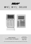
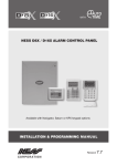
Ness aComms Install & User Manual
Phone GUI
Tablet GUI
1|Page
TABLE OF CONTENTS
Copyright Notice ................................................................................................................................................................................... 2
Important Information ................................................................................................................................... 3
Ness D8x / D16x Versions....................................................................................................................... 3
D8x / D16x Two-Way Communication Settings ...................................................................................... 3
Wiring Diagram .............................................................................................................................................. 4
Hardware / Parts Required ...................................................................................................................... 4
IP232 Ethernet to Serial Bridge Settings ..................................................................................................... 5
Ness aComms Configuration Setup ............................................................................................................ 7
IP Address ............................................................................................................................................... 7
Port Number ............................................................................................................................................ 7
Panel Type .............................................................................................................................................. 7
Zone Names ............................................................................................................................................ 7
AUX Output Names ................................................................................................................................. 7
Using the App ................................................................................................................................................ 8
Understanding the icons .......................................................................................................................... 8
Arm to away mode ................................................................................................................................... 9
Arm to Home / Monitor mode .................................................................................................................. 9
Activating Emergency Alarms .................................................................................................................... 10
Panic…. ................................................................................................................................................. 10
Fire...… .................................................................................................................................................. 10
Medical ................................................................................................................................................. 10
Viewing Zone status .................................................................................................................................... 11
Controlling the AUX Outputs ...................................................................................................................... 12
Troubleshooting .......................................................................................................................................... 13
Why Can’t I contorl the AUX Outputs? .................................................................................................. 13
I can’t control anything on the panel using the app? ............................................................................ 13
Why doesn’t the Panic, Fire or Medical buttons work? ........................................................................ 13
Can I Control my D8x / D16x over the internet using 3G? ................................................................... 13
COPYRIGHT
All rights reserved. No part of this publication may be reproduced, transmitted or stored in a retrieval system in any form or by
any means, electronic, mechanical, photocopying, recording, or otherwise, without the prior written permission of Ness.
Ness reserves the right to make changes to features and specifications at any time without prior notification in the interest of
ongoing product development and improvement.
© 2012 Ness Corporation Pty Ltd ABN 28 069 984 372
Android is a trademark of Google Inc
2|Page
IMPORTANT INFORMATION
Ness D8x / D16x Versions
The Ness aComms app only works with version 5.6 and above of the D8x and D16x PCB.
To control the AUX outputs in the Ness aComms App you must be using a D8x/D16x PCB
version 7.8 or above.
D8x / D16x Two-Way Communication settings
The two way communications on the D8x / D16x will only work if the following programming locations
are enabled on the panel:
P 199 E
1E ON: Send Address.
2E ON: Send Time Stamp
3E ON: Send Alarms.
4E ON: Send Warnings.
5E ON: Send Access Events.
Panic, Medical & Fire control
If you want to control the Panic, Medical & Fire in the Ness aComms app then you need to make sure
you have the following programming locations enabled in the D8x or D16x.
P 126 E
1E ON: (Double key PANIC)
2E ON: (Double key FIRE)
3E ON: (Double key MEDICAL)
P 62 E
4E ON: Shortcut Keypad Panic
P 64 E
7E ON: Keypad Fire Alarm (STD LCD KP)
8E ON: Keypad Medical Alarm (STD LCD KP)
3|Page
WIRING DIAGRAM
The Ness aComms app requires the D8x / D16x to be on a TCP/IP network.
Although the panel doesn’t have a TCP/IP connection you are required to use an Ethernet to serial
bridge to add the panel to your network.
Ness Part Number K-6002 includes the D8x-D16x Serial Lead 3 Way – Panel to DB9 and
IP232 Ethernet to serial bridge which it required to connect your panel to the network.
Hardware / Parts Required:
1 x D8x-D16x SERIAL LEAD 3 WAY - PANEL TO DB9
1 x IP232 ETHERNET TO SERIAL BRIDGE
You need to connect the white serial plug into the D8x/D16x and connect the other end into the IP232
Ethernet to serial bridge as shown in the image above, and then you need to connect the IP232
Ethernet to serial bridge into a wireless router/switch.
D8x/D16x Panel
Black
Blue
White
IP232 Ethernet to Serial Bridge
PIN5
PIN2
PIN3
4|Page
IP232 ETHERNET TO SERIAL BRIDGE SETTINGS
Before any connection can be made, you need to make a few changes in the IP232 Ethernet to serial
bridge.
To do this you need to open the IP232 Config Utility program which is available from the Ness
product page for the IP232 Ethernet to Serial Bridge.
You must be running at least version 1.1.0 or above of the IP232 Config Utility software.
You need to make sure that you have your network cable plugged into the IP232 Ethernet to
serial bridge and make sure that it’s connected to the same network your computer is
plugged into before continuing.
Now you need to click on the Search button, this will go and search for these IP232 Ethernet to serial
bridges on your network.
Once it finds an IP232 Ethernet to serial bridge it will display down the bottom how many was found,
as well as showing it in the dialog along with its MAC address and IP address.
If it fails to find any IP232 Ethernet to serial bridges it will come up with the following error:
5|Page
Once it finds your IP232 Ethernet to serial bridge, click on it and select Configure.
You now need to enter / change some settings in the configure screen.
1. You need to make sure you set the IP address to a static IP address.
2. You need to enter in an IP address for this RS232 Ethernet to serial bridge.
This should be on the same network range as your Android device. (e.g. 192.168.0.xx)
If you are unsure what IP settings to use you might need to contact the network administrator.
3. You need to set the Baud rate to 9600 as that is what the D8x/D16x communicates on.
4. The TCP Port to accept connections should be set to 2401.
This port number can be anything, but recommended to use the default 2401.
5. Once the settings have been entered, click on the ‘Send Settings (to IP232)’ button.
This will apply all the settings to the IP232 Ethernet to serial bridge.
6|Page
NESS ACOMMS CONFIGURATION SETUP
When you run Ness aComms for the first time, it will ask for your network settings as shown below:
You can also view this screen at a later time by pressing the settings button up the top right
of the main screen.
IP Address
The IP Address is what you entered into the IP232 Ethernet to serial bridge from the previous page.
Your Android Device is required to be on the same IP network and network range as your IP232
Ethernet to serial bridge. If you are connecting to your panel over 3G (mobile network) then port
forwarding is required to your network. Please refer to portforwading.com on how to set that up.
Port Number
The Port Number is what you entered into the IP232 Ethernet to serial bridge from the previous page.
Default Port is 2401.
Panel Type
You need to select the Panel Type of your panel that you are using.
If you are using an 8 zone panel select Ness D8x, if your panel is a 16 zone panel then choose Ness
D16x.
Zone names
By pressing the Edit Zone Names allows you to edit the name of the zone which you see in the GUI.
AUX Output Names
By pressing the Edit Output Names allows you to edit the name of the Output which you see in the
GUI.
7|Page
USING THE APP
Understanding the icons
Area is Disarmed
Zone is Normal
Area is Armed
Zone has be violated
Area is Armed to Monitor / Home
Mode
Zone is in alarm
Area is Armed to Day Mode
Panic / Fire / Medical is active
Panel has a low Battery
Panic / Fire / Medical is Normal
Panel is alarm
AUX / Output is OFF
AUX / Output is ON
8|Page
Arm to away mode
To arm the panel, you need to press the Arm button followed by your user code then press the E
button.
Arm to home / monitor mode
To arm the panel to home/monitor mode, you need to press the Home button followed by your user
code then press the E button.
This feature needs to be enabled in the panel.
Disarm the panel from away or home / monitor mode
To disarm the panel, you just need to enter in your user code followed by the E button.
9|Page
ACTIVATING EMERGENCY ALARMS
The Panic, Fire and Medical alarms will only work if it’s been enabled in the panel.
You have 3 different alarms to choose from:
Panic
Fire
Medical
Once you tap on the alarm buttons (Panic, Fire, Medical) it will ask you to confirm if you really want to
activate the alarm before it sends the request to the panel. This is in case you tap it by mistake.
Panic
The panic button will send a panic alarm to the alarm panel.
Fire
The Fire button will send a fire alarm to the alarm panel.
Medical
The Medical button will send a medical alarm to the alarm panel.
10 | P a g e
VIEWING ZONE STATUS
You can view the zone status from the panel by clicking on the Zones button up the top left of the
screen.
If you are running a tablet and the screen is 7” or bigger, then the zones button will not
appear on the screen as the zones will be on the screen already.
There are 3 different states
Zone Normal
Zone Violated
Zone is in alarm
Each zone status is updated automatically when a zone is violated or becomes back to normal.
You can rename each zone name by opening the settings screen.
Phone GUI
Tablet GUI
11 | P a g e
CONTROLLING THE AUX OUTPUTS
To control the AUX Outputs in the Ness aComms app, you must have a version 7.8 or above of
the D8x/D16x PCB.
You can tap the AUX Output to activate/deactivate the output at any time.
The AUX outputs have 2 states:
AUX Output is OFF / Normal
AUX Output is ON / Active
You can rename each AUX Output name by opening the settings screen.
12 | P a g e
TROUBLESHOOTING
Why can’t I control the AUX Outputs?
The outputs can only be controlled by version 7.8 and above on the D8x / D16x. Although you can use
the outputs on the keypads (such as the navigator keypad or KPX) and view the status in the Ness
aComms app, there is no serial protocols in earlier boards to turn the output on or off via the serial port.
I can’t control anything on the panel using the app?
The Ness aComms app will only work if the following is enabled on the panel:
P 199 E
1E: ON (Send Address.)
2E: ON (Send Time Stamp)
3E: ON (Send Alarms.)
4E: ON (Send Warnings.)
5E: ON (Send Access Events.)
6E: ON (Send Zone Seal State. (D8x/D16x V6 and later.))
Make sure your IP address isn’t being used by another device on your network, and make sure you
Android device is connected to the same network as the panel.
Why doesn’t the Panic, Fire or Medical buttons work?
Make sure you have the following programming locations enabled in the panel:
P 126 E
1E: ON (Double key PANIC)
2E: ON (Double key FIRE)
3E: ON (Double key MEDICAL)
P 62 E
4E ON: Shortcut Keypad Panic
P 64 E
7E: ON Keypad Fire Alarm (STD LCD KP)
8E: ON Keypad Medical Alarm (STD LCD KP)
Can I control my D8x / D16x over the internet using 3G?
Yes, however you will need to enable Port Forwarding in your router.
For more information on how to enable port forwarding please visit www.portforwarding.com for
detailed step-by-steps on port forwarding.
13 | P a g e