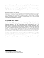
1
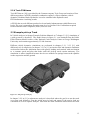
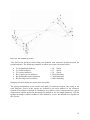
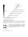
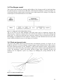
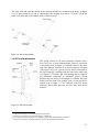
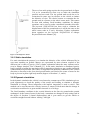
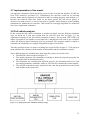
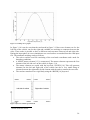
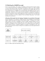
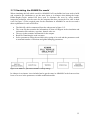
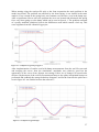
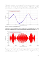
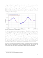
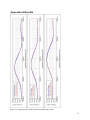
Figure 3.13: Bump curve profile
In figure 3.14 it can be seen that the road mesh in figure 3.12 have one element row for the
left side of the vehicle, one for the right and a middle row working as connector between the
sides. These make it possible to have a different road curvature between left and right side.
During the input phase in a new simulation a new road surface are meshed from the road input
file. The automatic meshing works as follows.
• The solver read the road file consisting of the road node coordinates and a node for
boundary conditions.
• A M3D49 master element [13] is constructed. The master element represents the first
element of the left side row on the vehicle in figure 3.14.
• The master element are copied with the keyword *ELGEN [16]. This will generate
elements for the left and right side of the vehicle but also a very small string of
element between the right and left side element with the task to connect the two sides.
• The road are transferred to a rigid body using the *RIGID [16] keyword.
Figure 3.14: First column of road mesh
9
General membrane element
30