1
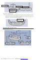
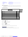
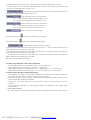
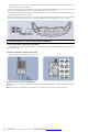
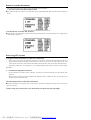
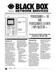
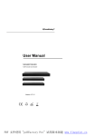
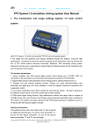
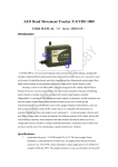
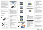
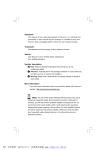
FOXTECH
Fly higher & see farther
ALL-IN-ONE GOGGLES
User Manual
FV01
Before using this FPV system, please read this manual carefully and keep it properly for future reference.
PDF 文件使用 "pdfFactory Pro" 试用版本创建 www.fineprint.cn
Contents
Notice…………………………………………………………………………………………………………………….
Start Guide………………………………………………………………………………………………………………
1. About Wireless Video FPV……………………………………………………………………………………………
2. About the Components of FPV System………………………………………………………………………………
3. Working Principle of FPV System………………………………………………………………………
4. R/C Device Compatible with FPV System……………………………………………………………………………
Installation…………………………………………………………………………………………………………….
1. Install Glasses Antenna………………………………………………………………………………………………
2. Install Transmitter Antenna………………………………………………………………………………………….
3. Install Transmitter, Camera…………………………………………………………………
4. Install Glasses and R/C Remote Controller…………………………………………………………………………..
5.External power supply of the glasses………………………………………………………………………….
Operation Guide for Video Glasses……………………………………………………………………………………
1. Schematic Diagram of Glasses…………………………………………………………………………….. ………..
2. Video Glasses Power on/off…………………………………………………………………………….. …………..
3. Function Setup Menu…………………………………………………………………………….. ………………..
1). Operation guide of buttons………………………………………………………………………
2). Menu function explanation……………………………………………………………………………..
4. Volume, Image Brightness and Contrast Adjustment…………………………………………………………………
5. Glasses Wireless Reception Channel Adjustment…………………………………………………………………
6. Glasses AV in/out……………………………………………………………………………..
7. Dispersing lens replacement(dispersing lens to be purchased seperately)………………………………
Operation Guide for Camera and Transmitter………………………………………………………………
1. Power on/off Video Camera and Transmitter…………………………………………………………………………
2. Wireless Transmitter Channel Adjustment……………………………………………………………………………..
3. Video Camera Lens Focus Adjustment……………………………………………………………………………..
Remote Controller Parameters ……………………………………………………………………………………
1. Set Video Camera Pan-tilt Working Channel ………………………………………………………………………
2. Set R/C Remote Controller DSC Function……………………………………………………………………………..
Start Using EPV System ………………………………………………………………………………………………
1. Image Reception and Sound Test of Wireless Transmission…………………………………………………………
2. Test of Head Tracking Function…………………………………………………………
3. Test of Reception Distance of Wireless Transmission…………………………………………………………
4. Start FPV flight…………………………………………………………
Other Functions …………………………………………………………………………………………………
The application of the following functions must be supported by the other products of the Company.
1. AV recording during flight ……………………………………………………………………………………………
2. GPS navigation ……………………………………………………………………………………………
3. Watch movies with FPV system……………………………………………………………………………………
Precautions of Using the FPV System …………………………………………………………………………………
1. The wireless transmission and reception distance of the FPV system………………………………………
2. How to prevent the remote controller being interfered…………
3. The working frequency of the FPV system……………………………………………………………
4. How to prevent the FPV system producing interference or being interfered…………………………………
5. Selection of the wireless reception and transmission frequency of the FPVsystem…………………………………
6. The application of more than two FPV systems at the same time in the same field or within the effective receiving
scope……
Troubleshooting …………………………………………………………………………………………………
1. The glasses display has no images……………………………………………………………
2. The head tracking system does not work……………………………………………………………
3. Bad image signals received by the glasses or short wireless transmission distance………………………………
Specifications …………………………………………………………………………………………………
Notice
PDF 文件使用 "pdfFactory Pro" 试用版本创建 www.fineprint.cn
n The FPV system cannot be used unless it conforms to the local laws and regulations on wireless application and can
be used only for models.
n If this product undergoes the modification, adjustment and parts replacement by others rather than us, we will not
bear any consequence resulting therefrom.
n Never use this product in the environment having same frequency; otherwise, the consequence of troubled flying
will occur due to interfered images.
n Please carefully check and test the functions of this product before use; Do not take off before these functions are
tested normal.
Start Guide
1. Wireless Video FPV Introduction
n The full name of WIRELESS VIDEO FPV is First Person View of the Wireless Video, which is called “FPV” in
short.
1. About the Components of FPV System
①GS920 Glasses (1)
③ Data cable (1)
⑤ Antenna (2)
⑦AV cable
②CM210 video camera (1)
④ TS330 2.4G wireless AV transmitter (1)
TS331 5.8G Wireless AV transmitter (1)
⑥ Shade(1)
⑧ Elastic Bandage (1)
PDF 文件使用 "pdfFactory Pro" 试用版本创建 www.fineprint.cn
3. Working Principle of FPV System
①This system consists of two modules:
n Video camera and transmitter module: On the plane model, a video camera and an video transmitter are
installed; the video camera has an electrical pan-tilt that can move upward, downward, leftward and
rightward; and the pan-tilt controls the upward, downward, leftward and rightward movements according to
the glasses’ head tracking signals received by R/C receiver.
n Reception and display module: The operator wears glasses that are inbuilt with a wireless AV receiver and a
virtual large screen real-time image display. The glasses and the R/C remote controller are connected via a
data cable. The R/C remote controller supplies power for the glasses via the data cable while the glasses send
the output signals of the head tracker to the R/C remote controller; then the remote controller transmits in
wireless manner the head tracker signals and model control signals together to the R/C receiver on the model;
the videos and audios taken by the video camera on the model plane; then the glasses can receive the video
and audio signals transmitted from the model plane within certain distance. The operator wearing glasses can
view images from the virtual display in the glasses and hear sound from the headset in the glasses. With this
FPV system, the operator can have virtual flying experience.
② Work principle diagram:
CM210 video camera
Model plane
R/C receiver
Wireless AV transmitter
R/C remote controller
GS920 glasses
Data cable
Video glasses imaging effect
4. R/C Device Compatible with FPV System
① The models of the R/C remote controller supported by this FPV system include FUTABA FF-7, FF-8, FF-9,
T9Z, T12MZ and T14MZ. For other types of RC controllers, please consult the distributor.
PDF 文件使用 "pdfFactory Pro" 试用版本创建 www.fineprint.cn
② The operation demonstration in this manual uses FF9 R/C.
Installation
1. Install Glasses Antenna (as indicated in Fig. 1)
n According to the working frequency, choose a 2.4GHz or 5.8GHz antenna and install it onto the SMA port of
the glasses by turning it tight. The antenna shall be kept in vertical state.
Fig. 1
2. Install Transmitter Antenna (as indicated in Fig. 2)
n According to the working frequency, choose a 2.4GHz or 5.8GHz antenna and install it onto the SMA port of
the transmitter by turning it tight. The antenna shall be kept in vertical state.
Fig. 2
3. Install Transmitter, Camera Head and R/C Receiver
CM210 video recorder
Connection of video recorder
Wireless AV transmitter
Steering gear
Steering gear
RC receiver
To battery
4 Install Glasses and R/C Remote Controller
n First, power off the R/C remote controller, insert the 4PIN plug on one end of the data cable into the data
socket of the glasses, the 6PIN plug on the other end of the data cable into the DSC socket on the back of the
R/C remote controller.
PDF 文件使用 "pdfFactory Pro" 试用版本创建 www.fineprint.cn
6PIN plug
4PIN plug
GS920 glasses
R/C remote controller
Data cable
5. External power supply of the glasses
n The glasses can work with power supply provided by the R/C remote controller via the data cable. If no R/C
remote controller is used for powering up the glasses, the external power port of the glasses can be used for
supplying power. The voltage of the external power supply shall be at 8-13V. And the specs of the power port
of the glasses is 2.5mm, positive inside and negative outside.
Power port
Inside + and outside -
Operation Guide for Video Glasses
1. Schematic Diagram of Glasses:
PDF 文件使用 "pdfFactory Pro" 试用版本创建 www.fineprint.cn
拨盘 Driver plate
亮度调节键 Brightness key
接收天线 Receiving antenna
眼罩 Shade
镜片 Lens
音量调节键 Volume key
对比度调节键 Contrast key
电源开关/复位开关/电源指示灯 Power switch/Reset switch/Power indicator
数据线接口 Data cable port
电源接口 Power port
2. Power on/off Video Glasses:
n
Press the power key on the glasses for about 3s to power on the glasses; in such case, the power indicator will
be on; press the power key on the glasses for about 3s again to power off the glasses; in such case, the
indicator will be off.
3. Menu Function explanation :
①Turn the driver plate to the position of “0”, then the screen of the glasses will display the main operation menu:
Main Menu
Main Menu
1. RX frequency
2.4GHz
2. PAN CH select
CH5
3. TILT CH select
CH6
4. PAN range
+/- 45o
5. TILT range
+/- 45o
6. Color
7.AUTO correct
ON
② The functions of keys in the Menu
Volume increase key
Volume reduce key
Brightness increase key
Brightness reduce key
moving among menu items
moving among menu items
confirm
back to previous menu
③ Turn the driver plate to the position of non-zero and then exit from the main operation menu.
2) menu functions explanation
①
Set working frequency at 2.4GHz/5.8GHz:
If 2.4GHz is chosen, the glasses can receive 8 channels of wireless AV signals with frequencies at 2.4GHz;
PDF 文件使用 "pdfFactory Pro" 试用版本创建 www.fineprint.cn
Submenu
If 5.8GHz is chosen, the glasses can receive 8 channels of wireless AV signals with frequencies at 5.8GHz.
② 2. PAN CH select CH5 Set head tracker signal output channel of PAN axis: choose CH5 and insert the servo head
of PAN servo of the pan/tilt to the CH5 of RC receiver.
③
Set head tracker signal output channel of TILT axis: choose CH6 and insert the servo
head of TILT servo of the pan/tilt to the CH6 of RC receiver.
Set the sensing range of PAN axis of head tracker
o
+/- 45 : The maximum testing angle in horizontal direction is 45º.
+/- 90º: The maximum testing angle in horizontal direction is 90º.
Set the sensing range of TILT axis of head tracker
o
+/- 45 : The maximum testing angle in vertical direction is 45º.
+/- 90º: The maximum testing angle in vertical direction is 90º.
Set the color saturation level of the display
Press volume increase key
Press volume reduce key
to increase color saturation level of the display
to reduce color saturation level of the display
set the automatic compensation of the head tracker
ON: When the sensed head tracker movement angle deviates more than +/- 4o from the actual movement angle, the
goggle compensates the movement angle to actual angle.
+/- 20: When the sensed head tracker movement angle deviates more than +/- 20o from the actual movement angle, the
goggle compensates the movement angle to actual angle
+/- 10: When the sensed head tracker movement angle deviates more than +/- 20o from the actual movement angle, the
goggle compensates the movement angle to actual angle
OFF: Auto correction function is then disabled.
4. Volume, Image Brightness and Contrast Adjustment:
①
②
③
④
For the following operations, make sure the driver plate is not at the position of “0”.
Volume adjustment: Press the volume key “+” to turn up, “-” to turn down.
Image brightness adjustment: Press the brightness key “+” to brighten images, and “-“ to darken images.
Image contrast adjustment: Press the contrast key “+” to increase contrast, and “-“ to decrease contrast.
5. Glasses Wireless Reception Channel Adjustment:
① If the transmitter uses 2.4GHz, in the menu settings of the glasses, choose the frequency 2.4GHz; if the transmitter
uses 5.8GHz, in the menu settings of the glasses, choose the frequency 5.8GHz.
② Rotate the driver plate to choose 1-8 reception channels and make sure the channel number of the glasses is the
same as and consistent with that of the transmitter.
③ During testing, if bad image quality occurs due to interference, switch to the other channels to avoid such
interference.
④ It is noticeable that, during flight, you cannot adjust the channel of the transmitter, so, before flight, test the
useable channels.
6. Use of Glasses AV in/out:
① AV in: The composite video signals and analogue audio signals from peripheral devices (such as DVD, MP4) are
PDF 文件使用 "pdfFactory Pro" 试用版本创建 www.fineprint.cn
input the AV IN socket of the glasses; the operator can see the images on the screen of the glasses and hear the
sound from the headset of the glasses.
② AV Out: The AV signals received in wireless manner by the glasses will be outputted from the AV OUT socket of the
glasses via AV cable, connected to DVR or screen to display images and make sound.
③ Use of headset: By inserting a standard 3.5mm headset into the AV IN socket of the glasses, you can hear the sound
received by the glasses in wireless manner.
7.Replacement of dispersing lens (optional): The design of the glasses allows for replacing lens in order to facilitate
those with short sight. The dispersing lens is optional and include such specifications as 200º, 400º and 600º.
Operation Guide for Video Camera and Transmitter
1. Power on/off Video Camera and Transmitter:
Insert the power plug into the battery socket to power the video camera and transmitter while pull the power plug
out to power them off.
2. Wireless Transmitter Channel Adjustment:
Adjust the toggle switch to adjust among Channels 1-8.
3. Video Camera Lens Focus Adjustment:
n When the screen of the glasses displays unclear images, rotate the lens with hand to adjust the focus until the images
are clear.
n When the images are unclear due to the dirt on the lens, clear the lens with soft cloth or other special tools.
PDF 文件使用 "pdfFactory Pro" 试用版本创建 www.fineprint.cn
Remote Controller Parameters
The instructions in this manual adopt FUTABA T9CHP R/C remote controller.
1. Set Video Camera Pan-tilt Working Channel
n If the pan-tilt of the video camera is set at CH5, CH6, then set [TRAINER]5CH, 6CH of the R/C remote controller at
FUNC.
3. Set R/C Remote Controller DSC Function
n When the DSC switch H of FF9 is pulled to the upward position, then the screen will display “ON”. During use, H
switch should be kept at ON.
Start Using EPV System
1. Image Reception and Sound Test of Wireless Transmission:
① Power on the video camera, the transmitter and then the video glasses, adjust the channel numbers of the video
glasses and the transmitter until they become the same. In such case, you can see the videos taken by the video
camera on the screen in the glasses and hear the sound sensed by the mike of the video camera from the headset.
② If the image performance is not satisfactory, you can adjust brightness and contrast to reach the optimal display
performance.
2
Test Head Tracking Function System:
① Set the parameters of the R/C remote controllers according to the related instructions and then pull the DSC
switch on.
② Move the glasses upward, downward, leftward and rightward, observe whether the video camera pan-tilt will
bring the video camera do the same.
3 Test Reception Distance of Wireless Transmission:
n Keep the transmitter and the glasses with certain distance and observe whether the images on the screen of the
glasses are normal.
4. If the system passes all the above tests, then launch your plane and enjoy FPV flight.
PDF 文件使用 "pdfFactory Pro" 试用版本创建 www.fineprint.cn
Other Functions
The application of the following functions must be supported by the other products of the Company.
n AV recording during flight: The videos received by the video glasses can be output to the external DVR via AV OUT
to record the whole flight.
n Flight with GPS navigation: If GPS devices are installed on the model plane, then you can see flight height, distance
and position of flight, battery voltage, current, etc on the screen of the glasses.
n Watch movies with FPV system: Connect the AV signals of such devices as DVD, MP4, DVB, etc to the transmitter,
then the glasses can receive AV signals in wireless manner within certain distance and thus wireless cinema can be
realized.
Precautions of Using the FPV System
1. The wireless transmission and reception distance of the FPV system:
n The wireless transmission and reception distance of the FPV system may vary greatly due to the barriers between the
receiver and the receiver, because the FPV system transmits images and sound with very high frequency, 2.4GHz and
5.8GHz. Under such high frequency, wireless waves can have only rectilinear transmission. With small barriers, the
transmission distance in air between the transmitter and the receiver is the longest; if there are such barriers as
mountains, houses, trees, etc, the distance will become short. Therefore, during use, if the quality of images is
becoming worse at certain distance, it indicates the flight will exceed the maximum transmission distance. In such
case, shorten the flight distance in order to prevent image signal loss and FPV system failure.
2 How to prevent the remote controller being interfered:
n First, it must be make cleared why wireless receiving and transmitting devices have interference problem? Two
wireless systems working at the same frequency will produce interference or interfere with each other. The actual
consequences include bad reception signals or signal interruption and shortened wireless communications working
distance.
3.
The working frequency of the FPV system:
n This system uses 2.4GHz or 5.8GHz wireless transmitting and receiving devices. This frequency belongs to ISM
frequency band, which is opened to civilian by the government, so you can use it without any application to the
competent authority of the government. However, as anyone can use the open ISM frequency band for their devices,
the FPV system may interfere with the devices at this frequency of others, or the FPV system will be interfered with
by the devices of others at the same frequency.
4. How to prevent the FPV system producing interference or being interfered:
There are two methods to solve the problem of the FPV system of interfering or being interfering:
① Avoid interference by setting the working frequency of the glasses. If the current frequency is interfered and thus
images are of low quality or short distance, adjust the frequency selection button of the glasses to change the
working frequency of the glasses; in addition, we need to change the frequency of the wireless transmitter of the
video camera to the corresponding working frequency.
② Choose one open field or the place without ISM frequency transmitting devices nearby.
5. Selection of the wireless reception and transmission frequency of the FPV system:
n If non-2.4GHz R/C devices are used, the working frequency of the FPV system should be set at 2.4GHz in order to
obtain the best FPV flight distance and this will depend on the maximum control distance of your R/C devices.
n If 2.4GHz R/C devices are used, choose 5.8GHz as FPV transmitting and receiving function in order to avoid the
interference caused due to the same frequency and this depends on the maximum control distance of your R/C
PDF 文件使用 "pdfFactory Pro" 试用版本创建 www.fineprint.cn
带格式的: 字体颜色: 自
动设置
devices.
6. The use of more than two FPV systems at the same time in the same field or within the effective
receiving scope:
①Make sure that every FPV system use a different channel and the spacing between the channel numbers of the
FPV systems is large enough to prevent mutual frequency interference and achieve the optimal application effect.
Troubleshooting
1
The glasses display no image:
① Check if the power supply voltage of the glasses is at 8-13V or if the glasses are powered on.
② Check if the reception frequency of the glasses is at 2.4GHz or 5.8GHz and consistent with that of the
transmitter; check if the reception channel of the glasses is consistent with that of the transmitter.
③ Check if the power supply voltage of the transmitter is at 8-13V and the power plug is inserted properly.
④ Check if the video camera plug is inserted into the transmitter.
⑤ Check if the antennas of the glasses and the transmitter are installed.
2
The head tracking system does not work:
① Check if the servo cable plug of the pan-tilt of the video camera is inserted into the corresponding channel
socket of the R/C receiver.
② Check if the channel number set under “Head tracker signal output channel” in the glasses is consistent with
that of the R/C receiver inserted into the steering gear cable of the pan-tilt of the video camera.
3. Bad image signals received by the glasses or short wireless transmission distance:
① Check if the FPV system is using 2.4GHz frequency when 2.4GHz R/C remote controller is used. The FPV
system then should choose 5.8GHz frequency.
② Check if there are wireless transmitting devices of the same frequency nearby causing interference. The FPV
system should choose any other frequency to avoid such interference frequency or avoid using the system in
the same field with the same frequency.
③ Check if the antennas of the glasses and the transmitter are installed.
④ Check if there are mountains, houses, trees etc between the glasses and the transmitter. Always use the FPV
system in open field.
Specifications:
GS920
Display resolution
VGA 640x480RGB, 922k pixel color display
Field of view
32º diagonal
Virtual image size
48 inches diagonal at 2m
Wireless receiver frequency
2.4G Hz 8-channel
5.8G 8-channel
Antenna connector
SMA
Power supply
8-13V, 300mA
CM210
Imaging sensor pixels
1/3 inches CCD sensor, pixels:628 x 582
Horizontal resolution
420TV lines
View Angle
90º
Lens focus:
3.6mm
Video output level
1V p-p @75Ω
Audio output level
1V p-p @10KΩ
PDF 文件使用 "pdfFactory Pro" 试用版本创建 www.fineprint.cn
Power supply
9-13V
TS321
Wireless transmit frequency
2.4GHz 8-channel
Antenna connector
SMA
Video input level
1V p-p @75Ω
Audio input level
1V p-p @10KΩ
Power supply
8-13V
Transmission distance
2000m
TS351
Wireless transmit frequency
5.8GHz 8-channel
Antenna connector
SMA
Video input level
1V p-p @75Ω
Audio input level
1V p-p @10KΩ
Power supply
8-13V
Transmission distance
800m
PDF 文件使用 "pdfFactory Pro" 试用版本创建 www.fineprint.cn