1
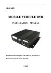
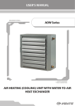
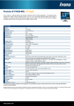
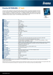
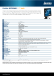
AH DV1 AH DV1 USER MANUAL ISSUE:09/11/2009 1 AH DV1 INDEX Foreword………………………………………………………………………………… 3 Presentation ……………….……………………………………………............. 4 Technical data and cross-sectional images…………………………………………. 5 Norms and certifications …………………………………………………………….. 7 Alert and identification labels on the cabinet………………………………………… 8 Mounting and environmental conditions …………………………………………….. 10 Multiplexing of two cabinets …..…………………………………………………….. 11 Connection of sidewalls……………………………………………………………… 12 Kickplate mounting…………………………………………………………………….. 14 Lighting…………………………..………………………………………………… 15 Electrical connections…………………………………………………………………. 15 Temperature control………………………………………………………………….. 17 Cabinet Merchandising………………………..……………………………………… 18 Defrost and drain……………………………………………………………………… 18 Defrost, electrical boxes and outlets for copper pipes ……………………………. 20 Maintenance, cleaning and technical services ……………………………………. 21 Recycling …………………………………………………………………………. 22 Spare parts …………………………………………………………………………. 23 Electrical schemes……………………………………………………………………… 25 ISSUE:09/11/2009 2 AH DV1 1. Foreword This guide has been prepared taking into account AH DV1 Freezer. In general the following details were examined - How to use the cabinet - Specifications - Installation and assembly - Product information and recommendations for users - Maintenance operations The manufacturer does not carry any responsibility in the following conditions -Cabinet misuse - Faulty installation - Electrical effects - In the case of periodic maintenance performed - Operational changes - Original spare parts not used - Failure to comply with the information Note: Electricity-related applications, it is dangerous for your life Everyone should read this guide before uses the cabinet ISSUE:09/11/2009 3 AH DV1 2. Presantation AH DV1 case produced for frozen foods. This cases is suitable to use for large supermarkets and hypermarkets with high performance and large display area.This case have been designed to able to meet all customer expectation. ISSUE:09/11/2009 4 AH DV1 3. Specifications Cross Section Drawing CE cross section drawing ISSUE:09/11/2009 5 AH DV1 TECHNICAL DATA SHEET ISSUE:09/11/2009 6 AH DV1 4. Norms and Certifications Used as a reference for cabinet certifications and approved norms;EN 60204-1; EN 60439-1; EN 60439-2 CLIMATIC ENVIRONMENTAL CONDITIONS (EN 441-4) These cabinet ambient temperature was tested according to class 3. Climatic Dry air conditions temperature 1 16˚C 2 22˚C 3 25˚C 4 30˚C 5 40˚C 6 27˚C Relative humidity %80 %65 %60 %55 %40 %70 Dew point 12˚C 15˚C 17˚C 20˚C 24˚C 21˚C This case has designed according to following directives EEC 73/23 , EEC 98/37 ISSUE:09/11/2009 7 AH DV1 5. Alert and identification labels on the cabinet ISSUE:09/11/2009 8 AH DV1 High voltage label High voltage label is located on the bottom of the cabinet, at the top electrical box. Product Description label Description label is located at the middle of case on the same side with electrical box and it is including all technical information. 1 Manufacturer logo and address information 2 Product model 3 Product's serial number 4 The product's production history 5 Conditioning of the product class 6 Minimum temperature of the product 7 Refrigerants used in the product 8 Operating voltage values 9 Product certificates and in accordance with the directives approved 10 Product certification and quality certificates of manufacturer 11 Evaporator fan power 12 Lighting electrical power 13 Defrost the electric power resistance 14 Electric power of blowing resistance 15 Electric power of drainage resistance 16 Electric power of glass resistance 17 Total electric power Transport label Cabinet is fitted with a pallet for transport. There is transport label at the back side of case. ISSUE:09/11/2009 9 AH DV1 6. Mounting and environmental conditions Please Follow the instructions below for assembly Cabinet positions that do not leave and do not mount. If there is an explosive gas near heat sources If there is air flow ISSUE:09/11/2009 10 AH DV1 7. Multiplexing of two cases For combining two or more cabinets, please follow the following order. - Remove the side walls (if there is any) - Bring cabinets side by side. - Remove palette. Set foot height of cabinet then bring them to scale. Using a spirit level to check the accuracy of case. Check the balance by moving the Cabinet. Please follow the steps below for multiplexing of two cabinets. Side Pillar Connection -Please use connection parts at bottom of pillar and tighteen with keys for connection. (figure 1, 2 ve 3) Be used connection parts and parts cabinet location as shown at figure 4 Figure 1 Figure 2 ISSUE:09/11/2009 Figure 3 11 AH DV1 POS NO 1 2 3 4 PARTS NAME Cabinet Side Pillar M10x110 Hexagon-headed bolt M10 Washer M10 Nuts UNIT On the Cabinet 1 2 2 Figure 4 Body Connections Two cabinet have to screwed with connection sheet from cabinet as shown figure 5 Figure 5 8. Connection of Side walls Please placed the insulation to inside of pillar base and stick adhesive tape to body before sidewall connection.(figure 6). You can do side connection from as Shown point in Figure 7 and 8 with M12x100 plastic bolts and nuts to connect. ISSUE:09/11/2009 12 AH DV1 Place the support plate inside to side thermopane profile (figure 9) and screwed to the uprights.(figure 10) Figure 6 Figure 7 Figure 9 ISSUE:09/11/2009 Figure 8 Figure 10 13 AH DV1 9. Kickplate connection Figure 11 POS NO 1 2 3 4 PART NAME Front Kickplate 4,2x13 Screw Cabinet Leg Side Kickplate UNIT 1 12 On the cabinet 2 First, please connect front kickplate from kickplate connection point to leg.Please put plastic tires to front kickplate then hold side kickplate which will coincides with connection holes as shown in figure 12 and use screw for connection. Please put plastic tires to side kickplate. Connection parts as shown in figure11. Figure 12 ISSUE:09/11/2009 14 AH DV1 10. Lighting Used LED lighting inside the case. Figure 14 Figure 13 Inserted the LED lamps into the case First plastic led lamp connection (figure 14) is screwed to the sliding glass plastic. LED lights should pressed up and installed to the connection plastic (figure 13) 11. Electrical Connection Electrical and pilot box in the closet long edge, is located in a sub. (Figure 15) LED lighting electric box is located at the middle wall. (figure 16) ISSUE:09/11/2009 15 AH DV1 Figure 16 When making electrical connections should be examined following details. Important! Before making electrical connection cabinet defined label and product information, books and electrical diagrams for further details. Protected automatically switches should used against electrical currents. In an emergency user should know the location of accessible key. Grounding should be at the electrical system Maximum voltage change must guaranteed of ± 6% Thickness of the cable power lines must be at least 2.5 mm ² and high current must be able to carry. Power line cable should not be long then 4-5m, depending on the case if cable length must increased the cable cross-section must increased. As the temperature and humidity to be suitable for cabinet. Make sure you have the climate class 3 (+25 o C, RH 60%) Electricity staff should have electrical certificate ISSUE:09/11/2009 16 AH DV1 12. Temperature Control Temperature control done with hair bulb in the front suction. Figure 17 Important: a pilot control module must make with a max of Section 3. PILOT CABINET PILOT CABINET 1. ADD-ON CABINET PILOT CABINET 1. ADD-ON CABINET ISSUE:09/11/2009 2. ADD-ON CABINET 17 AH DV1 13. Cabinet Merchandising False increases the formation of ice storage. Make sure that storage products does not cover air return grill. Closed air holes reduces the capacity of the cabinet and defrost process lengthens(Fig. 18) Figure 18 14. Defrost and drain These procedures prevent the cabinet sweats,smell bad inside of case, escape cooled air. On the AH DV1, cabinet that the ice melts is carrying out through resistance. Thermostat is being assembled cabinet by experts and set changes not allowed. After end of the ice resolve cabinet will start to work automatically. To taken of defrost water Cabinet shipped with, drainage on the part of drain hose is attached (fig. 21) turn this drainage to clockwise side and makes the connection. -Connect the hose to the edge of the water goes. - Before first run placed some water to drainage. ISSUE:09/11/2009 18 AH DV1 Figure19 Drainage of a piece to be installed to the cabinet; Figure21 Figure20 ISSUE:09/11/2009 19 AH DV1 15. Drainage, electrical box and copper pipe outlets According to the cabinet module drainage, electrical boxes and outlets for copper pipe is shown below. (Figure 22) Şekil 22 A : electric B: drainage C: copper pipe ISSUE:09/11/2009 20 AH DV1 16. CARE AND CLEANING Long life and satisfactory performance of any equipment is dependent upon the care it receives. To ensure long life, proper sanitation and minimum maintenance costs, these display Cases should thoroughly cleaned, all debris removed and the interiors washed down, weekly. Fan Plenum To facilitate cleaning, the fan plenum is hinged and also fastened with screws at each end. After cleaning be sure the plenum is properly lowered into position and that screws are reinstalled OR PRODUCT LOSS WILL RESULT due to improper refrigeration. Exterior Surfaces The exterior surfaces should clean with a mild detergent and warm water to protect and maintain their attractive finish. NEVER USE ABRASIVE CLEANSERS OR SCOURING PADS. Interior Surfaces The interior surfaces may cleaned with most domestic detergents, ammonia based cleaners and sanitizing solutions with no harm to the surface. DO NOT USE: Abrasive cleansers and scouring pads, as these will mar the finish. Solvent, oil or acidic based cleaners on any interior surfaces. ! WARNING DO: Remove the product and all loose debris to avoid clogging the waste outlet. Store product is in a refrigerated area such as a freezer. Remove only as much product as can be taken to the freezer in a timely manner. First turn off refrigeration, and then disconnect electrical power. • Thoroughly clean all surfaces with soap and hot water. DO NOT USE STEAM OR HIGH ISSUE:09/11/2009 21 AH DV1 WATER PRESSURE HOSES TO WASH THE INTERIOR. THESE WILL DESTROY THE DISPLAY CASES SEALING CAUSING LEAKS AND POOR PERFORMANCE. Remove screws and lift fan plenum for cleaning. BE SURE TO REPOSITION THE FAN PLENUM AFTER CLEANING DISPLAY CASE. Take care to minimize direct contact between fan motors and cleaning or rinse water. Rinse with hot water, but do NOT flood. NEVER INTRODUCE WATER FASTER THAN THE WASTE OUTLET CAN REMOVE IT. Allow Display Cases to dry before resuming operation. After cleaning completed, turn on power and refrigerant to the Display Case. Verify that Display Case is working properly 17. Recycle Parts All countries are disposing of waste according to EU laws and norms Current Recycle Parts on the case Painted Metals :Pillars ,shelves ,legs, back panel, base tray, ceiling Cupper, Aluminium :Evaporator and electrical parts Stainless Steels :Bottom panels painted panels ,basic parts , base tray Polyurethane :Thermal injection Thermopane :Glass parts PVC :Handrails Polystyrene :Side endwalls Polycarbon :Led Lighting cover ISSUE:09/11/2009 22 AH DV1 Spare Parts INPROGRESS ISSUE:09/11/2009 23 AH DV1 ISSUE:09/11/2009 24 AH DV1 Electrical Schemes ISSUE:09/11/2009 25 AH DV1 ISSUE:09/11/2009 26 AH DV1 ISSUE:09/11/2009 27 AH DV1 ISSUE:09/11/2009 28