1
BIG CEE
S T U D I O S
FLW Instruction Manual
The housing for this electronic sculpture was designed and built by J. Christopher Krok
of Big Cee Studios. However, the concept and circuitry of the four letter word generator
at the heart of the sculpture was created by Raymond Weisling of Zetalink Technologies.
The text on the following pages is reproduced from the original User Manual for the 2003
model of The Four Letter Word, documentation release version 2.5. It is presented here
verbatim to maintain the original intent of Mr. Weisling’s description of his work. The
sole exception is under the “User Settings” section, where the physical description of the
settings switches have been modified to represent the use of toggle switches on the Big
Cee housing, compared to the DIP switches referenced in the original text.
Further information on Mr. Weisling’s work can be found at the Zetalink Technology
website, www.zetalink.biz, under the “Chronotronics Products Division” link.
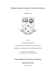
The display tubes used in the FLW are the Burroughs B-7971. These tubes were used in
various applications, including the display of price information on the New York Stock
Exchange, and were produced circa 1968-1972. The manufacturer’s data sheet lists a
lifetime of 50,000 hours for these tubes, and the circuitry operates the tubes below their
full brightness to further increase lifetime. Experimenters have found that these tubes
will last for decades under “recreational” use, but as they are no longer manufactured, the
FLW should be turned off when not in use. If needed, spare tubes are occasionally
available on Ebay.
J. Christopher Krok
bigcee.com
BIG CEE STUDIOS
THE FOUR LETTER WORD
SCOPE
This manual is intended for the Four Letter Word Kit, model FLW3K. This kit is a major
update to the previous design sold as a kit, model FLWK. There are only a few
similarities between these kits, at the hardware level, due to the extensive number of
design changes that went into the new version. The new model performs much like the
previous one, but with many operational improvements and an increased number of
words that are possible.
HISTORY
The Four Letter Word was first produced by Raymond Weisling in 1973 and appeared in
the June 1973 issue of Playboy magazine. Approximately 50 units were built between
1973 and 1975. In 1994 reconstruction of the piece was started using a small number of
parts still on hand, enough for about four units, but for a variety of reasons it was
sidetracked and somewhat forgotten. In 2001 several thousand of these jumbo Nixie
tubes were found in a barn loft somewhere in rural New England. Their renewed
availability, coupled with the power of Internet to locate them and people interested in
Nixie technology, prompted the completion of the work begun in 1994. The 2002 version
was an intermediate step, combining aspects of the 1994 work with several new ideas.
The 2003 model expanded considerably on that. The latest version is an item that may
look much like the original (depending on what kind of plastic case is used), but
operationally is totally different from the original. The technology employed in the
reconstruction was simply not available in 1973. Word generation is vastly improved and
several very entertaining word-game modes have been added. And to add a little
practical functionality, it now also has a clock feature to show time, though its function as
a clock was not the main intent.
OPERATION
When the unit is first turned on it will always display a greeting message: “FOUR
LETTER WORD BY RAYMOND WEISLING” followed by the internal program version
number, and then the word PLAY. At this point it will read and respond to the user
settings on the DIP switches and begin displaying words. Due to internal and external
indeterminate processes, the order and selection of words is always different. There
should be no discernible patterns or sequences of words.
The indeterminate processes utilize pseudorandom number generators in the internal
program and external oscillators that are read in parallel as a number at certain points.
Because these oscillators use imprecise components and do not in any way operate
synchronously with the program, the combination of the two results in considerable
indeterminacy, which is often called randomness.
FLWK3-DOC © 2003 Raymond Weisling & Zetalink Technology Indonesia — Rev 2.5 (0418) 2
USER SETTINGS
Eight switches are provided on the back of the housing for setting different operational
(performance) modes or user preferences. The switches are read at the beginning of
each new word display cycle. In certain performance modes it may require some time
before the word is finished displaying. Note that “ON” represents a switch in the up
position.
Switch position 1 = ON
When set to ON this selects the “stick hangman” mode. In this mode a word is chosen
internally while the display is completely blank. Then individual segments that form the
letters are turned on in an indeterminate sequence until the entire word is displayed in
full.
Switch position 2 = ON
This selects the “letter hangman” mode. In this mode a word is chosen internally while
the display is completely blank. Individual letters are turned on or enabled one at a time
until the whole word is visible. The sequence of segments enabled and their timing is
varied and indeterminate.
Both this and the “stick hangman” mode are especially entertaining to watch because
you invariably try to guess the word before it completely appears. It is even more fun
with a friend—it can become a game.
Switch position 3 = ON
This switch controls the normal display mode for words. When set to OFF a continuous
stream of words is displayed at a fairly rapid speed. The actual period of time is
somewhat indeterminate. When set to ON the same mode remains selected, but the
changes are slower. This switch is primarily intended for adding the normal mode to a
mixture of the other hangman modes, but also doubles as a speed control for the normal
mode.
Switch positions 1 or 2 or 3 = ON (any two ON, or all three ON)
When more than one of the first three positions (1, 2 and 3) are ON, then the unit enters
a mixed display mode. Words are arbitrarily shown in normal (all at once), letter
hangman or stick hangman modes, depending on which switches of these three are set
to ON. This is the only time that position 3 is functional to select its mode. It adds or
subtracts the normal mode to one or both of the hangman modes. With these you have
complete control of all three modes mixed any way that you wish.
Switch position 4 = ON
This switch enables the low-priority clock time mode. The clock has no battery
backup, so each time electric power is turned off and then back on the clock must be set
to the correct time. If the time has not been set, the clock mode is disabled regardless of
the position of this switch. Once the user has set the time, with this switch set to ON, the
FLWK3-DOC © 2003 Raymond Weisling & Zetalink Technology Indonesia — Rev 2.5 (0418) 2
time is displayed every 20 seconds (minimum), but only inserted in between two words
in sequence. If a word change occurs before the 20 second limit is reached, the time
display is deferred until the next word change. In the hangman modes this can end up
being considerably longer than 20 seconds. The clock display is brief, and involves rapid
flashing of the digits for about one second, so as to attract attention. Time is fleeting,
catch it if you can.
Switch position 5 = ON
This switch enables the high-priority clock mode. In this mode both hangman modes
are disabled. The words are displayed in the normal mode, alternating with the clock
display, which appears without flashing. In both clock modes the seconds are shown by
the underline segments, which represent a horizontal bar that starts at one segment (for
1 to 14 seconds) and extends to all four underlines (for 45 to 59 seconds); the first
second of each minute has all four underline segments off.
When the high-priority clock mode is selected, switch positions 1 to 4 control the display
speed for the clock and word display. Switches 1 and 2 control the duration of the word,
and switches 3 and 4 control the duration of the clock display. The higher number switch
of each pair has a greater weight in determining the duration.
If the clock has not been set since the last time power was turned on, then this mode will
be inhibited, and Switches 1 to 4 will be ignored, even for mixed modes. Once the time is
set by means of the buttons, the clock becomes active. There is no way to turn off the
word display. The Four Letter Word is not a clock; it is primarily a word entertainment
device.
Switch position 6 and 7
These two positions control the appearance or nonappearance of impolite, vulgar or socalled “dirty” words. There are four possible settings of these two switches as follows:
SW7
OFF
OFF
ON
ON
SW6
OFF
ON
OFF
ON
Resulting operation
Unaltered or neutral operation (no bias, no censorship)
Vulgar words biased to appear once every 7-14 minutes
Vulgar words biased to appear once every 3-10 minutes
Full censorship of vulgar words
The two selections to bias vulgar words to appear use indeterminacy in setting the
interval of time between appearances and which word is selected from a list of about 20
such words. When full censorship is selected, none of the words in the same list is
allowed to be displayed. There is no way to create your own list of these words. Your
sensibilities and sensitivities may differ with what is pre-programmed for this function.
The unaltered or neutral mode does not treat these words with any greater or lesser
frequency.
FLWK3-DOC © 2003 Raymond Weisling & Zetalink Technology Indonesia — Rev 2.5 (0418) 2
Switch position 8 = ON (and position 6 and 7 = OFF)
This switch enables a special mode that approximates, or roughly emulates, the
operation of the 1973 version of the Four Letter Word. That version did not have a
microcomputer or any memory chips—such technology was just appearing on the
horizon and was prohibitively expensive. Instead, each Nixie tube was arranged to only
display ten letters out of the full alphabet. The ten letters chosen was adjusted to be
different for each of the four tubes, based on analysis of English four-letter words. A
separate counter for each tube rapidly sequenced through the ten letters, and
periodically a snapshot of the counter value was grabbed and sent to the tube drivers,
where the segments to make the letters were encoded by means of a diode matrix.
Letter position 2 only had 8 letters since the 9th and 10th most frequent letters were
much further down the frequency list and the highest two were especially frequent
(consequently they were doubled). Thus 8000 different words could be displayed, of
which only about 900 were real English words (a list of these still exists). In this mode
DIP switch positions 1 to 5 are ignored. The clock set and advance buttons can be used
to decrease or increase the display speed (they have no effect on the clock time, which
is not displayed, but continues to run internally).
If both DIP switches 7 and 8 are ON, then the 1973 emulation is not selected. Instead
the Word Bank is inhibited and words only appear based on frequent letter pairs (letter
pair algorithm). This is only available with Version 5-1 firmware or later.
If both DIP switches 6 and 8 are on, the letter pair algorithm is inhibited and only words
from the Word Bank are selected. These are always real words, names, and
abbreviations; imaginary or “future” words will never appear. This is only available with
Version 5–5 firmware or later.
SETTING THE CLOCK
The clock hours and minutes are set by pressing one of two buttons. The SET (S) button
should be pressed once, at which time the Nixie tube display should show the hours.
The ADVANCE (A) button is then clicked until the hours desired appears. Then press
the S button again to select the minutes digits, and then press the A button to move
forward. The A button can be held down to quickly advance the digits. When the minute
has been set, wait for that actual minute shown to begin, and then press the S button to
return to the word display. The seconds, as shown by the underline segments, are reset
to zero when S button exits the clock-setting operation.
CLOCK TIMEBASE
The clock timekeeping is based on the local electrical power grid frequency, which is 60
Hertz (Hz) in North America and a few other isolated places, and 50 Hz most
everywhere else. Generally the power generation authorities maintain long-term stability
of this frequency, but it might go slightly up and down over a shorter time period. Your
Four Letter Word must be assembled with R4 and R7 placed to indicate which frequency
is to be used. (FLW units assembled by Big Cee Studios are set to 60 Hz.)
FLWK3-DOC © 2003 Raymond Weisling & Zetalink Technology Indonesia — Rev 2.5 (0418) 2
WORD BANK
While the main goal of the 1973 version was to make words by random selection of
letters that were weighted for English, the occurrence of real words was quite low
(technology was limited). The 2002 version added a list of 1344 real words (limited by
available memory), called a Word Bank. This was expanded further in this 2003 version
by development of several new compression schemes. The present Word Bank holds
over 2200 words in eight different internal database structures.
One of these structures, for example, has three of the four letters of a word explicitly
encoded (in from three to five bits per character), while the fourth letter is indicated by a
single bit in a field of bits that correspond to a set of letters (from 12 to 19 letters, never
all 26, are in different sets).
For example, #EAR might be one entry, where # is a variable, bit-encoded field with bits
set corresponding to the valid occurrence B, D, F, G, H, N, P, R, S, T, W and Y in real
words. Thus one such database entry could take the place of separate database entries
of these words: BEAR, DEAR, FEAR, GEAR, HEAR, NEAR, PEAR, REAR, TEAR,
WEAR and YEAR, given that the software knows how to process the data correctly, and
each of the variable letters is represented in the bit map field.
Four separate database structures having this basic form exist, for each of the four
letters being the variable (#), namely #AAA, A#AA, AA#A and AAA# (where A
represents any alphabetic character). These tables consume about 2100 bytes and
contain over 1700 words, for an efficiency of around 1.25 bytes per four-letter word.
Words that do not fit into the above scheme, or whose variable field was too sparse to
be efficient (e.g. #UOY, where only B is valid: BUOY) are encoded into several other
tables using a different encoding process which uses two bytes per word. Some unusual
words that would not fit into any other scheme are stored as 4 ASCII bytes.
WORD GENERATION BY RULES
Considerable research and analysis, done periodically over a 30 year period (”I do have
other interests”: Weisling), went into developing the word generation scheme. To begin
with, about 2500 English four-letter words were analyzed and three tables of letter-pair
frequencies were derived. For example, the word BALE would have a count of one for
the appearance of BA, AL and LE added to the tables for these pairs. For this version of
FLW, short tables consisting of the most frequent letter pairs for each position were
made. Each letter pair is encoded into one byte for storage.
Position 1 pairs include: AI, AR, BA, BE, BO, BR, BU, CA, CH, CL, CO, CR, CU, DA,
DE, DI, DO, DR, DU, FA, FI, FL, FO, FR, FU, GA, GE, GI, GL, GO, GR, GU, etc.
Position 2 pairs include: AI, AK, AL, AM, AN, AP, AR, AS, AT, AV, EA, EE, EL, EM, EN,
ER, ES, HA, HE, HI, HO, IC, ID, IK, IL, IN, IP, IS, IT, IV, LA, LE, LI, LL, LO, LU, NI, NO,
NT, NU, etc.
FLWK3-DOC © 2003 Raymond Weisling & Zetalink Technology Indonesia — Rev 2.5 (0418) 2
Position 3 pairs include: AD, AL, AN, AR, AT, CE, CH, CK, DE, DS, ED, ES, ET, FE, FT,
GA, GE, GY, ID, IL, IM, IN, IP, IR, IT, KA, KE, LD, LE, LL, LT, LY, MA, MB, ME, MP, ND,
NE, NG, NK, etc.
This is another one of the word generating schemes, which can make real words and
statistically-probable nonwords. Such as BA+AM+MP = BAMP.
Further rule checking discards words with three consonants or vowels in a cluster, such
as ODST, DRFY, or EAIS.
CIRCUIT DESCRIPTION
The heart of this device is the microcontroller, a Motorola MC68HC705C8A device that
has 7684 bytes of program storage and 176 bytes of RAM. The program is stored in
one-time programmable memory and is protected from copying or downloading. If you
attempt to read the contents of the chip you will fail and might damage the part. The
program is copyright by the author and represents an investment of considerable effort,
both in recreational linguistic research, word database design and assembly language
programming.
This 2003 model uses multiplexing to display characters on the nixie tubes. Only one
tube at a time is turned on, but the rotation or sequencing occurs so quickly that you see
a steady display of four characters. Multiplexing requires 15 transistors to turn on each
segment (cathode), and four transistors to connect each tube’s anode to the highvoltage power in sequence.
For those interested in the multiplexing details, nixie tubes are somewhat difficult to
multiplex due to the high voltages switched, the large tube and printed circuit board
geometries involved, which increase parasitic capacitance, and the relatively low current
required to strike ionisation at a level that can be seen as a dim glow. The capacitance
charges up to the potential, and if left charged when transistors switch off, can lead to
ghosting and even reversed polarity (the anode mesh can itself glow at random pinpoints
with glowing clouds surrounding them). The circuit in the FLW employs resistors from
each cathode and each anode connected to a common intermediate voltage. Electronic
circuit designers are familiar with pull-down and pull-up resistors. These are, in effect,
pull-middle resistors. If there are any free-floating cathodes and anodes left charged
after the transistors switch off, the charges are both brought to the same middle voltage,
approximately half of the full high voltage. Not only is ghosting eliminated, it also
appears to help silence acoustic buzzing noises that have been reported when
multiplexing some types of nixie tubes.
Other circuit details that might puzzle the reader of our schematic must be considered in
terms of functional options available with the FLW and also must consider that the same
PCB is used for our GeekKlok product. That design needs additional components and
interacts to a certain degree with the circuit of the FLW. Consequently some circuit and
mechanical provisions to allow all options to peacefully coexist on the same board were
implemented, though not all can be realised with components at the same time.
FLWK3-DOC © 2003 Raymond Weisling & Zetalink Technology Indonesia — Rev 2.5 (0418) 2
RANDOMNESS AND INDETERMINACY
Microcomputer programmers can simulate randomness in software by creating and
manipulating pseudorandom number generators. However, since microcomputers
basically start operating the same program steps when power is applied, the result is
that a pseudorandom generator always begins its operation from the same state, so the
sequence of random numbers produced is always the same. Even if started at a different
step ("seeded" with a different start value), the sequence from number to number is
always the same. To produce an apparent degree of randomness requires an external
source of imprecise and non-repeatable information not related or in any way
synchronized to the internal program.
The Four Letter Word has a five-bit indeterminacy generator external to the
microcontroller, consisting of five simple oscillators each with a different frequency,
determined by external components (resistors and capacitors) of imprecise values.
These oscillators operate at very approximately 100, 300, 450, 600 and 1400 Hz. Thus
the relationship between individual oscillators is itself indeterminate, as each one
oscillates at its own free-running frequency. When read as a parallel five-bit number, the
value read is quite certain to be sufficiently unpredictable. The number read in on U2–31
through U2–36 is then used internally to set certain parameters or to cause the internal
pseudorandom number generators to further scramble their data.
Randomness cannot be made more random, but pseudorandom generators can be
made less determinate by altering their sequences or occasionally skipping over a step
(shifting two times instead of once). There are four 16-bit nonlinear feedback shift
register pseudorandom sequencers, and each one is shifted at the same time, but based
on the external five-bit value, one or more of the four generators is allowed to jump
ahead to a different sequence, allowing the four different 65535-step sequences to slip
out of phase with each other. Some parameters only require an 8-bit (or smaller)
number, and these are taken, at different points in the program, from the high or low
bytes of the 16-bit register, so this makes it seem like there are eight sources of
pseudorandom numbers. With all of these factors combined, events are truly
indeterminate. You may use the word “random” when describing it to visitors if you wish.
This indeterminacy is used to select letter pairs, Word Bank records, which mode is used
next (when mixed modes are selected). It is also used to select hangman letter or
segment appearance sequences and numerous other attributes of operation to produce
a varied and interesting display. The operation of the pseudorandom generator coupled
with the external oscillators has been carefully adjusted to give the highest degree of
unpredictability possible, simply because words are so easy to remember and thus any
repeating patterns would potentially be easy to discern.
FLWK3-DOC © 2003 Raymond Weisling & Zetalink Technology Indonesia — Rev 2.5 (0418) 2