1
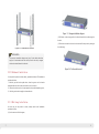
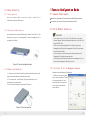
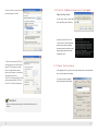
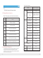
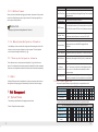
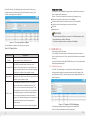
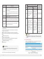
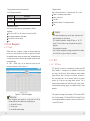
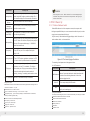
16/24 Ports Managed
PoE Ethernet Switch
16/24FE POE+2GE
User Manual
Preface
The user manual mainly introduces the product shape, product
positioning, hardware installation, Web management and other
related information.
I l l u st r a t i o n
(1)Format of Graphics Interface
Format
< >
[ ]
Description
“<>”means button name, such as “click <Confirm> button”.
“[ ]”means window name, menu name and data table, such as“pop out [New
user] window”.
“/”is used to seperate Multi-level menu. Such as [file/new/folder] multi-level
/
menu [file] menu [new] sub-menu [folder] menu option.
(2)Va r i o u s S igns
Caution
Instruction
Improper operation may damage the device or cause data loss.
Supplemental instruction for operation contents.
Content
1 Product Introduction
1.1
1.2
1.3
1.4
Overview
Product Feature
Board Diagram
Specification
2 Installation
2.1 Shipping List
2.2 Installation Precautions
2.2.1 Safety Precautions
2.2.2 Installation Requirements
2.2.3 The Requirements of Electromagnetic Environment
1
1
1
1
3
4
4
4
4
5
5
6
6
2.3 Installation Way
2.3.1 Rack Installation
2.3.2 Workbench Installation
2.3.3 Wall-hung Installation
7
7
2.4 Cable Connection
2.4.1 Device Connection
2.4.2 Configuration Cable Connection
2.4.3 Power Cable Connection
9
9
9
9
3 Function Configuration Guide
10
3.1 Computer Requirements
10
3.2 Set up Network Connection
3.2.1 Set Static IP for the Management Computer
3.2.2 Confirm the Network Connection by Ping Command
3.2.3 Cancel the Proxy Server
10
3.3 Web Page Configuration Guide
3.3.1 Start and Login
3.3.2 Change Language
3.3.3 Common Buttons Introduction
3.3.4 The Default Configuration
3.3.5 Web Users Timeout
3.3.6 Backup System Configuration Information
3.3.7 Restoring the Configuration Information
3.3.8 Quit
10
12
12
13
13
14
15
15
17
17
17
17
4 Web Management
4.1 System Status
4.2 Port Configuration
4.3 VLAN Setting
4.3.1 VLAN Configuration
4.3.2 VLAN forwarding
4.4 Trunk Management
4.4.1 Trunk
4.4.2 RSTP
4.5 Port Security
4.5.1 Static Address Latch
4.6 Web Management
4.6.1 SNMP Setting
4.6.2 Email Alarm
4.7 Network Statistics
4.7.1 Network Statistics
4.7.2 MAC Address
4.8 System Management
4.8.1 IP Address
4.8.2 User Management
4.8.3 Log Information
4.8.4 File Management
4.9 PoE Management
17
17
18
20
20
22
23
23
24
28
28
29
29
30
31
31
32
33
33
34
35
36
37
1
Product Introduction
Back panel
1.1 Overview
This item is a 16/24-port managed PoE Ethernet switch, which provides
16/24*100Mbps downlink PoE Ethernet ports, supports IEEE802.3 af/at and
2*1000Mpbs uplink Ethernet ports. It supports Layer 2 network management and
PoE management based on web and provides high-speed data forwarding. It is
widely used in security surveillance, network engineering projects and so on.
AC Power Input
Port
1.2 Product Feature
Ground
16 Ports 100M Managed PoE Switch Board Diagram
16/24 ports managed PoE Ethernet switch provides 16/24 * 10/100Mbps
downlink PoE Ethernet ports and 2 * 10/100/1000Mbps uplink Ethernet
Front panel
ports;
Recover IP & password
port
Provide web-based layer 2 network management and PoE management
with simple operation process;
Support high-speed data forwarding, perfectly designed for large flow of
Uplink Gigabit
Ethernet Port
video data forwarding in security surveillance;
Support one-key recovery of IP address & user password;
Excellent circuit isolation protection, lightning protection up to 2 KV ;
Quick installation, easy operation and convenient for wall/ desk/ rack
installation.
1.3 Board Diagram
100Mbps PoE Ethernet Port
Indicate Power
Working Status
24 Ports Managed PoE Ethernet Switch Board Diagram
Indicate downlink 10/100Mbps
Working Status
Front panel
Recover IP
address and
password
100M PoE
Ethernet
port
Uplink Gigabit
RJ45 Port
Indicate power
I ndicate downlink 10/100Mbps
status
PoE status
1
Back panel
AC Power Input
Port
Ground
2
1.4
Specification
2 Installation
Item
Products
Power
Description
Products
Mains on load
Anti-counterfeiting label is attached to switch's cover. Product damage
Voltage Range
AC 100~240V
caused by unauthorized disassembly is not covered under warranty.
Ethernet Port
250W
370W
1~16/24 Ports: 10/100Mbps Ethernet port,
adaptive control
UPLINK Ethernet port: 10/100/1000Mbps
Ethernet port
Transmission
Distance
1~16/24 ports: Recommended 120m Max.150m;
Uplink 1000Mbps Ethernet port: Max.150m
PoE Protocol
IEEE802.3af,IEEE802.3at
PoE Power Supply
End-span
PoE Power
Consumption
Network
Switch
Network Standard
EachPort≤30W,
Total ≤250W
Each Port≤30W,
Total≤370W
IEEE802.3 10BASE-T, IEEE802.3u 100BASETX, IEEE802.3ab 1000BASE-T, IEEE802.3z
Switch Capacity
16G
Management
Management
Management L2
ESD
Level 3, Per: IEC61000 - 4 - 2
Protection
Communication Port
Lighting Protection
Level 3, Per:IEC61000-4-5
Working Temperature
0℃ ~55℃
Environment Storage Temperature
al
Humidity
(non-condensing)
Mechanical
Caution
16 Ports PoE Ethernet Switch
Power Supply
Consumption
Network
Connector
24 Ports PoE Ethernet
Switch
P lease check the following items before installation, if any missing, please
contact your local dealer.
Quantity
Item
Name
Unit
1
Device
1
Set
2
AC Power Line
1
Piece
3
Accessories
1
Set
4
User manual
1
Piece
2.2 Installation Precautions
To avoid device damage or personal injury by improper use, please observe the
following precautions.
2.2.1 Safety Precautions
Instruction
- 40℃~85℃
This is level A product, which may cause radio interference in living
0~95 %
environment. Users may need to take corresponding and effective
Dimension (L×W×H)
442mm×124mm×44.5mm
Material
Sheet metal
measures to solve the problem.
Black
Color
Weight
2.1 Shipping List
2.79kg
2.69kg
Products are subject to change without prior notice.
3
4
Pull out the power plug before cleaning the switch. Do not use wet cloth nor liquid to
wipe or wash the switch;
Do not leave the switch close to water or wet place so as to prevent water or dampness
2.3 Installation Way
There are 3 installation ways: rack, workbench and wall-hung installation.
from entering into the switch;
Make sure the switch work in a clean environment. Excessive dust may cause
electrostatic adsorption, which will affect the equipment life and cause communication
Caution
failure;
The switch will work normally under the correct voltage. Please ensure the voltage
indicated on the switch corresponds to the power voltage;
To avoid the danger of electric shock, please do not open the switch case. Do not open
the switch case even if the switch is powered off;
Please pull out the power line before installing or moving the switch.
Grounding and anti-lightening can greatly increase the protection level of the
switch. please connect the earth terminal to the earth by using at least wire
20.
The accessories (including but not limited to power lines, etc.), which can be used for
the switch only, is prohibited for other applications.
2.2.2 Installation Requirements
The device should work in indoor environment to avoid thunder stroke. It is important to
Instruction
The diagram is for reference only, the products are subject to actual
product.
obey the following requirements no matter you install it in the cabinet or on the workbench
directly:
2.3.1 Rack Installation
Enough space (larger than 10cm) for air outlet so as to facilitate the heating
dissipation; Good ventilation system for cabinets and workbench;
Cabinet and workbench is sturdy enough to support the switch and it's accessories's
weight;
Cabinet and workbench have good grounding.
Installation process:
(1) Check rack grounding and stability;
(2) Use screws to fit hangers at the device board side; 2.2.3 The Requirements of Electromagnetic Environment
When it is working, the switch may be affected by external interference outside the system
through the ways of radiation and conduction. Please pay attention to the followings:
AC power supply is TN system, so it is necessary to use single phase power socket
(PE) which can protect ground wire so that the filter circuit can effectively filter out the
power grid disturbances;
The switch should work far away from high-power radio transmitters, radar
Figure 2-1 Install hangers diagram
transmitters, high-frequency devices;
Use electromagnetic shielding if necessary, such as shielded cable;
(3) Put the device on the rack’s bracket and move the rack along the slot to
Interface cables should be arranged indoor rather than outdoor to prevent over-
proper position ;
voltage and over-current caused from damaging to the signal port.
(4) Use screws to fit the installation hanger at rack’s fixed slot, make sure the
device is installed at rack’s bracket steadily.
5
6
Figure 2-3 Hangers installation diagram
(2) Drill holes on the strong position of wall and then drive the rubber plug into
the hole;
(3) Drive these screws into the hole for the rack and fix the product by aiming at
Figure 2-2 Install switch to the rack
the rubber plug .
Instruction
This product’s installation hangers are just to fix the switch rather than
support it. Use brackets under the device (fixed to the rack) to support
switch when install the switch to the rack.
Figure 2-4 Fix the switch on wall
2.3.2 Workbench Installation
You can put this product on clean, stable, grounded workbench. The installation
procedure is below:
(1)Carefully put the device upside down, clean the grooves on the chassis
backplane with soft cloth to make sure there is no oil or dust in it;
(2)Remove the stickers on the foot pad, paste the foot pad in backplane groove;
(3)Carefully put the device upright on the workbench.
2.3.3 Wall-hung Installation
You also can put the product on clean, steady vertical wall. Installation
procedure is below:
(1) Use the screws to fix the hangers;
7
8
2.4 Cable Connection
3 Function Configuration Guide
2.4.1 Device Connection
3.1 Computer Requirements
Use cross network cable or cross-over cable to connect PC or
other device with switch's Ethernet port;
2.4.2 Configuration Cable Connection
Use a network cable to connect all Ethernet ports ( Notice: The VLAN ID of this
Ethernet port must be 1) with management PC, and use management PC to
configure the PoE switch.
Make sure the management PC has already been installed with Ethernet adapter;
Use network cable connect Ethernet ports with network card of PC.
3.2 Set Up Network Connection
Instruction
(1) You need to set the IP of the PC and the switch in the same
network segment. The default IP address of the switch is 192.168.1.200,
gate is 255.255.255.0.
(2) The port to connect management PC for Web setting must be
management VLAN. By default, management VLAN is VLAN 1,and each
port of the switch is VLAN1.
(3) If you need to connect the remote network, please make sure the
management PC and the router can make this.
(4) This product can't assign the IP address for the management PC, you
need to set the management static IP by yourself .
Figure 2-5 Connect configuration cable
2.4.3 Power Line Connection
(1 ) Connect one side of switch’s power line with the switch's AC power port, and
connect the another side with external AC power socket;
(2)Turn on the power ,c heck if switch's AC power indicate light is on, on
3.2.1 Set Static IP for the Management Computer
Operation steps (take Windows XP as sample):
(1) Click <start> to enter the [start]
menu, select “control panel”. Double
click “network connection” icon,
means power connected correctly;
double click the “local connection”
(3)Use the power line snap to jammed the AC Power line.
icon, pop out “local connection
status” window.
Figure 2-6 Connect power line
9
10
(2) Click <property> button, enter "local
connection property" window.
3.2.2 Confirm the Network Connection by Ping Command
Operation Steps below:
(1) Click <Start> button to enter [Start]
menu, select [Run], pop out the dialog.
(2) Input "ping 192.168.1.200", click
<confirm> button. If there is equipment
response show in the pop out dialog,
that means network connection succeed,
otherwise please check if the network
connection is correct.
(3)Select "Internet protocol (TCP/IP),
click <property> button, enter”Internet
protocol (TCP/IP) property” window.
3.2.3 Cancel the Proxy Server
Select “ use the IP address below”
If this management PC use proxy server to visit the internet, then you must prohibit the
button, input IP address ( use arbitrary
proxy service, following is the operation:
value between 192.168.1.1~
192.168.1.254, besides 192.168.1.200)
and the subnet mask(255.255.255.0).
(1) In browser, select [ tool/Internet
option] enter [Internet option] window.
Click "OK" to finish the configuration.
Instruction
DNS server address can be empty or be filled in with the real server
address.
11
12
(2) Select “connection” tabs in [Internet
option] window, and click [LAN Setting]
button.
Caution
Please follow the steps to check if the switch is installed correctly:
(1) Whether the physical connection of the equipment is correct?
Use network line to connect the product’s network ports (except Console
port) with management computer network card, and ensure the link
indicator light of the network port is on.
(2) Whether the computer TCP/IP agreement setting is correct?
Your computer's IP address must be 192.168.1.x (x range is 1 ~ 254 and x
(3) Make sure the “Use proxy server for LAN”option is not selected. If selected, please
can not be 200, otherwise it will conflict with the product IP address
cancel it and click <yes> button.
192.168.1.200 ), subnet mask: 255.255.255.0.
(3) Whether the computer's port VLAN ID is 1?
The menu bar has the following options: [System Status], [Port Configuration],
By default, the management VLAN is VLAN 1, so as each port of switch.
[VLAN Settings], [QoS management], [link management], [Port Security],
[network management], [Network Statistics], [System management], [Exit] and
After inputting the correct password, click <Login in>, the browser will display
drop-down menu bar of the "language switching function". Click a option to
the product Web management page as the picture below:
make corresponding setting. The following will explain the function of each
option.
3.3 Web Page Configuration Guide
The browser version recommend:IE7 and later, Firefox browser, Chrome, 360
browser (IE7 and later).
3.3.1 Start and Login
This product web default IP address:
192.168.1.200, subnet mask:
255.255.255.0, administrator
account: admin, password: admin.
After installing the equipment
Web management page diagram
correctly and setting up the computer,
open the browser, input the switch
3.3.2 Change Language
default address in the browser
address bar: http://192.168.1.200 ,
then press the Enter key, the user
login page will show in front of you as
As shown below, in the upper right corner of the Web page, click on the dropdown menu bar, select [Chinese] or [English], to complete Web language
switching.
follows:
13
14
Table 3-2 Default Configuration
Options
Default Configuration
Web English language switching page diagram
Username / password
admin/admin
IP Address
Subnet Mask:255.255.255.0
MAC address table aging
time
300 Seconds
Ports Status
Enable
Ports Speed Rate
Auto-negotiation
Port duplex mode
Auto-negotiation
Flow Control
Open
Trunking
Port does not converge
Port Speed Limitation
No limitation for Speed
Port Link Type
Access
Management VLAN
VLAN 1
VLAN Function Mode
Port-based VLAN
3.3.3 Common Buttons Introduction
IP Address:192.168.1.200
System
Table 3-1 Web commonly used function buttons introduction
Button
Help
Function
Open the online help page of Settings page to display the help
information for current page.
Confirm
Submit the input i nformation and confirm the information the
current system provided.
Cancel
Cancel the current configuration input
Return
Return to the previous page
New page
Create a new project of the current page
Select all
Port
Select all the ports of the current page
VLAN
Refresh
Refresh the current configuration page
Delete all
To delete all configuration items the section selected
3.3.4 The Default Configuration
The following table lists some important default configuration of the switch, all
features will be described in details in following chapters. The default
MAC Binding
No Binding
RSTP
RSTP Function
Close
Network
Management
SNMP
Close
configuration is for most cases. Please reconfigure if the default configuration
does not match the actual requirements.
15
16
Specification
3.3.5 Web User Timeout
When you have left the Web setting page for a while, the system will log out and
return to the Web dialog box due to system time-out. Please log in again if you
want to proceed the operation.
Description
Display different time zones around the world. For example,
Word Time Zone select Automatically Adjust Daylight Saving Time in daylight
saving time zone.
Time
Configuration
You can select local time or use NTP
NTP is used when all the equipment clocks in the network
Instruction
have to be kept the same so as to ensure the accuracy of the
NTP Sserver
Web page login timeout setting defaults to 5 minutes.
System Time
PC Time
3.3.6
Backup System Configuration Information
Click <Backup> button to select the configuration file backup path, click <OK>
button to save the current configuration to the computer. The configuration
can be restored through the document [* .cfg] .
Device Name
clocks. Enter the correct NTP server’s IP address to start the
setup.
The current time of the device, if you did not get the NTP
updated time, then it will start to count from 0:00,1970.
Computer current time
Network identification device used to facilitate the integrated
management tools such as SNMP to judge different
equipment.
Contacts
Equipment maintenance personnel’s Contact Information
Contact Address
Equipment maintenance personnel’s Contact Information
Hardware address of the device is unique since it is
3.3.7 Restoring the Configuration Information
MAC Address
Click <Browse> button, select previous backup file[* .cfg], click <Recover>
button. The configuration information stored in the backup file will be restored to
the device, the configuration takes effect after the device restarts automatically.
3.3.8 Quit
Click the [Exit] menu item in navigation bar, return to the system status screen,
the login box will be popping out automatically till the next click on the page.
determined by the length of 48 bits (6 bytes), Hexadecimal
digits.
Pay attention to software release limit for the hardware
version. There are more functions in the updated software
Hardware,
Software Version version, some of which have new requirements about
Running Time
hardware version.
The time period since equipment has been running. when
the device is restarted, the time needed to be recalculated.
4.2 Port Configuration
16 port switch panel silkscreen port and Web port correspondence table
16 Ports Managed PoE Ethernet Switch
4 Web Management
4.1 System Status
The meaning of specification in the page shown as below.
Table 4-1 Specifications description
Web Port
Silkscreen Port(up)
Web port
Silkscreen
2
2
10
10
3
3
11
11
4
4
12
12
5
5
13
13
6
6
14
14
7
7
15
15
8
8
16
16
17
1
18
2
24 port switch panel silkscreen port and Web port correspondence table
24 Ports Managed Ethernet Switch/ PoE Ethernet Switch
Web Port
1 2 3 4 5 6 7 8 9 10 11 12
1 2 3 4 5 6 7 8 9 10 11 12
13 14 15 16 17 18 19 20 21 22 23 24
25
1
26
Silkscreen Port
(down)
13 14 15 16 17 18 19 20 21 22 23 24
2
Web Port
Silkscreen Port (up)
17
1
1
9
9
18
On the [Port security / Port Settings] page, you can observe all the current
Configuration direction:
switch port status information and can set [Port Enabled], [port rate], [Flow
To set the port 1-10 to 100Mbps half duplex mode, and disable the flow control
function, please follow these steps:
Control], [Port range], shown as figure 4-1.
Enter 1-10 (or click on the box in front of the port) in the range of ports;
Click the port speed drop-down menu to select 100Mbps;
Click dual- duplex mode on the drop-down menu to select half-duplex;
Click flow control the drop-down menu to select the Disable ;
Click Edit;
Operation ends.
Instruction
1-24 port for downlink RJ45 ports, at a rate of 10 / 100Mbps adaptive, which
can be manually set to 10M or 100M mode.
Figure 4-1 Port configuration diagram
25-26 port for uplink optical ports, at fixed rate of 1000Mbps.
The specification meaning in this page shown as below
4.3 VLAN Setting
Tabel 4-2 Specification
Switch supports two VLAN modes:
(1) Port-based VLAN mode: define VLAN members according to device port.
Description
Specification
Port Enable /
Disable
Display the data forwarding of the port. If a port is off, you
can not forward the data. Enabled by default.
Display the port configuration’s speed rate, including 10M,
100M, 1000M, auto-negotiation. It defaults to Auto-
Port Speed Rate negotiation, which means the port can automatically and
Duplex Mode
After you specify the port to a VLAN, specified VLAN Packets can be forwarded
by the port.
(2) 802.1Q VLAN mode: Defined by IEEE802.1Q protocol. Process the packets
by identifying the packets tags.
4.3.1 VLAN Configuration
directly connected the device on the other side to negotiate
On [VLAN / Port VLAN] page, you can observe the VLAN settings of all the
the port speed. It defaults to Auto-negotiation mode.
Display the port configuration’s duplex status, including full-
current port switch and can set several functions such as [Port range], [Link
type], [Default VLAN ID], [VLAN forwarding list], [vlan-untagged mark list] , as
duplex mode, half-duplex mode, and auto-negotiation mode.
shown in figure 4-2.
It defaults to auto-negotiation mode.
Choose whether to enable the function of flow control
When two switches have enabled the function of flow
control, if one of the two switches has congestion, it will
send message to the other switch to notify it to temporarily
Flow Control
stop sending messages or slow down the sending speed.
After receiving the message, the other switch will stop
sending or slow down the sending speed of messages so as
to avoid packet loss and ensure normal operation of
network services.
By default, the flow control function of the port is enabled.
Figure 4-2 Diagram of VLAN setting page
The meaning of the parameters on this page are as shown below.
Table 4-3 Parameter description as the following table:
19
20
Parameter
Description
Access :port, which is normally used for connecting
Port
Type
Received message
without Tag
devices, only belongs to one VLAN. By default, all ports
Link Type
are Access ports.
The default VLAN ID
Access
network devices.
port for the packet with
the corresponding
VLAN Tag.
Default VLAN ID
Enter the ID number which is needed to be divided.
(generally 1-4094)
message
message with
processing
and default VLAN
ID is the same,
receive the packet.
When the VLAN ID
Delete message Tag
before transferring it.
and default VLAN
ID is different,
When the VLAN ID
VLAN Forwarding
VLAN packets can be transferred, other will be discarded.
list
VLAN untagged
mark list
Received
When the VLAN ID
Trunk : port belongs to multiple VLAN and can receive and
send multiple VLAN packets. It is normally used to connect
Transferred
Received message processing
Compare port default
When VLAN ID
VLAN ID to check
allowed to pass
whether it is allowed by through in the VLAN
Port forwarded packets can be set in VLAN. Untagged
the VLAN ID, if yes, the
without a tag , but other can not.
Trunk
ID, then receive the
default message with
packet. If the VLAN
port VLAN ID
ID is not allowed to
corresponding VLAN
pass through the
Configuration Guide:
Tag; No, discard the
VLAN ID, the packet
Such as if port 1-10 has connected to a switch respectively, it is necessary to
packet.
is discarded.
divided port 1-10 into VLAN 20.
and default VLAN ID
is the same, remove
the tag and send the
message. When the
VLAN ID and default
VLAN ID is different,
and is allowed to
pass through the
port, maintain the
original tag and send
the message.
Enter 1-10 within the port range(or click on the box in front of the ports);
Choose Trunk on the menu(Switches connection is generally used with Trunk
Caution
mode);
Enter 20 to default VLAN ID;
Enter 1-10 to VLAN forwarding;
Enter on VLAN flag list based on actual relationship (the receiving and
sending of packets for port is shown in Table 4-4);
The default port VLAN and allowed VLAN must be existed
VLAN.
4.3.2 VLAN Forwarding
Press Set to save the setting;
On[VLAN / VLAN forwarding] "page, you can observe the current port
Operation ends.
VLAN forwarding information, shown in figure 4-3.
Instruction
VLAN ID range is 1-4094, VLAN flag list must be in the range of VLAN
forwarding list.
Table 4-4 Port processing of transferring and receiving message.
21
Figure 4-3 Diagram of VLAN forwarding
22
The page parameter description as the table shown.
Configuration Guide:
Table 4-5 parameter description
Such as connect the switch A’s 1-2 ports with switch
Description
Parameter
VLAN ID
VLAN Name
Select 1 and 2 ports;
VLAN ID needed to be changed
Click Save;
Change the VLAN name that need configuration
Switch B and Switch A in consistent procedure;
Configuration Instruction:
B’s 1-2 ports
Enable a convergence group in switch A;
End.
Such as revise VLAN20 name from sales department to financial
department.
Caution
Enter 10 to VLAN ID (or click on the box in front of the VID10);
Enter financial department to VLAN Name;
In the same convergence group, the port speed, duplex mode, and
Press Revise to save the setting;
basic configuration must be consistent.
End.
STP consistent configuration, including STP ports on / off, STP
4.4 Trunk Management
4.4.1 Trunk
priority, STP cost, whether to open loop guard and root guard, or
edge ports.
QoS configuration is consistent.
TRUNK means port convergence, configure the software settings and
VLAN
connect two or more physical ports to become a logical path to increase
port of VLAN ID. Link type on the ports is consistent.
consistent configuration, including permitted VLAN, the default
the bandwidth between switches and network nodes. The bandwidth merge
of several ports provides an exclusive high bandwidth several times than
an independent port.
On [LACP / TRUNK] page, you can observe the current port link
convergence information, shown in Figure 4-4.
4.4.2 RSTP
4.4.2.1
RSTP Uses
STP (Spanning Tree Protocol) is established in accordance with IEEE
802.1D standard. It is developed for the elimination of the data link
layer loops in the LAN protocol. Devices running this protocol exchange
packets with each other to find loops in the network, and choose to
block some certain ports. This will eventually make the loop network
structure
into
a
loop-free
tree
pruning
network
structure.
Thus
it
prevents packet proliferation and infinite from cycling in loop network,
avoiding declined processing capacity and repeated receiving of same
messages.
Figure 4-4 Trunk link diagram
Instruction
STP contains two meanings, narrow meaning of STP is defined in IEEE
802.1D, board meaning of STP includs IEEE 802.1D defined STP and
Each convergence group supports up to eight ports.Port with the
various enhanced spanning tree protocol produced on the basis of STP
following cases can not be added to an convergence group:
(such as RSTP protocol).
(1) Port with 802.1x function;
(2) The mirror port;
(3) Port with MAC address binding.
23
24
4.4.2.2
STP Basic Concept
4.4.2.3
(1) The root bridge
RSTP Introduction
RSTP (Rapid Spanning Tree Protocol) is an optimized version of STP. It
Network structure tree must have a root, then STP introduces the concept
is"fast" because the delay is shortened under certain conditions when a
of root bridge in. Only one root bridge and the root bridge will change
port is selected as the root port and designated port to enter to the
when the network topology changes, so the root bridge is not fixed.
forwarding state, thus the time to reaching topology stability is greatly
(2) The path cost
reduced.
Path cost is a reference value for STP to select a link. By calculating the
path cost of STP, STP chooses stronger links to block redundant links and
cut the network into a loop-free tree topology.
Instruction
In RSTP, to ensure fast move of root port: the old root port of the device
(3) The port role
Root port: responsible for forwarding data to the root port.
has to stop forwarding data and the upstream designated port has to have
Designated port: responsible for forwarding data to the downstream of
started forwarding data.
network segment or switch port.
In RSTP, to ensure fast move of designated port: the designated port should
Block Port: port suppressed by other's specific ports.
(4) Port status
Forwarding: Forwarding user traffic, only the root port or designated port
be an edge port or a port connected to point to point link. If the designated
port is an edge port, the designated port can enter the forwarding state; if
have this condition.
designated port is a port connected to point to point link, the device can
Learning: The switch builds the MAC address table according to user
handshake with the downstream device to give immediate response to enter
traffic received (but not forwarding traffic).
forwarding state.
Listening: the completion of the root bridge, select the root port and
designated ports.
On [LACP / RSTP ] page can observe the current port RSTP information
Blocking: Only BPDU is received and processed, no user traffic forwarded.
on the switch, shown in Figure 4-5.
Disabled: consider blocking or link disconnection.
(5) The designated bridges and designated ports
The meaning of designated bridges and designated ports is shown in Table
4-6 below.
Table 4-6 Designated port status
Classification
For equipment
Designated Bridge
Designated Port
Equipment connecting directly
Port used by
with switch and responsible to
designated bridge to
transfer BPDU message to
transfer BPDU
switch
message to switch
Figure 4-5 RSFP page diagram
Port used by
Responsible to transfer
For LAN
designated bridge to
BPDU message to local network
transfer BPDU
segment equipment
message to local
The meaning of main parameters of the pages as below.
List 4-7 parameters description
network segment
25
26
Description
Parameters
As the network bridge priority, network bridge and
Device priority
network bridge MAC address combine as bridge ID, of
information. The port recover time is around 10s by default, click right key to
which minimum bridge ID will become the root network.
refresh current status。
Sending message
The interval needed to sent a BPDU data bag.
interval
Maximum
message lifetime
Changing port
status delay
Means the validity of a BPDU data package of a swtich
received from another switch.
The forward delay of a switch port status in transition
status(listening and learning).
Setting port path cost, only setting when port default path
Path expenditure
Caution
After setting RSTP, click “RSTP information”to check root bridge and port
4.5 Port Security
4.5.1 Statics Address Latch
Statics MAC address is to limit computer movement, the computer with
binding computer MAC and port can not communicate with other port, but other
computer can communicate with this port.
On [ Port security / Stastic address lock] page displays switch information of
statics address latch, as shown as below:
cost on “off” status Port link cost, with port priority and port
ID form port ID to compare Value range 1~200000000
“0”means automatic check.
The priority of port in network bridge, with port priority
Port priority
and port ID form port ID to compare. Default port
priority is 128.
Switch port and switch connect directly, then this port is
Point to point port P2P port, RSTP adopts negotiation mechanism for P2P
port so as to achieve quick transformation of port status.
The network edge switch generally connects with terminal
equipments, such as PC, workstation.To configure
Edge port
these terminal port to Edge port can achieve quick port
Figure 4-6 Port security page illustration
The meaning of main parameters of the pages as below. .
List 4-8 Parameters
Description
Parameters
Static MAC address differs from the general dynamic MAC
status transformation without the transformation of
discarding,Learning,Forwarding transformation course.
MAC Address
RSTP information Check RSTP information and port information
Configuration guide:
address. Once a static address is added, the address will
remain in effect until being delete and it is free of the
maximum aging time limit.
VLAN ID
Port-corresponding VLAN ID number
Enable RSTP function to avoid broadcast storm caused by looped network among switch A
,switch B and switch C 1-10 port.
Enable switch A,B,C RSTP function;
Enter 1-10 within the Port range (or click box front of port)
Equipment priority, cycle of sending message, maximum lifetime of information,
default port status migration delay;
Path cost, enter "0" is automatically detected;
Port priority, choose “128”;
Point to point, choose“yes”;
Edge port, choose “No”;
Click save, operation ends.
27
Port
Select a static MAC address to forward port, you can only
specify one forwarding port.
Configuration Guidelines:
For example, when binding the port 10 of switch A with switch B, port 1 belongs to VLAN20.
Enable static address latch function of switch B;
Enter the MAC address of switch B;
Enter VLAN ID with 20;
Enter port with 20;
Click Save;
Operation ends.
28
Caution
This feature is a security mechanism which requires high attention to the settings;
Do not use a multicast address as a enter address;
Do not enter the reserved MAC address, such as local MAC address;
For port which has already been added to an aggregation group, it is not allowed to
set binding between port and MAC address.
Caution
Community name: used to define the relationship between the SNMP
manager and an SNMP agent. If the community name SNMP packets
have not been recognized by the device, the packet is discarded. You can
use the standard community name (public or private) or a user-defined
group name.
4.6 Web Management
4.6.2 Email Alarm
4.6.1 SNMP Setting
The device has been running an event supervision, the supervision sends an
SNMP is used to ensure the management information transferred between any two points,
so that network administrators can easily retrieve information on any node on the network
and realize modify information, fault search, troubleshooting, capacity planning and report
generation.
SNMP contains NMS and Agent, of which NMS is a workstation running the server-side
program, while Agent is the client software running on net work device. NMS can send
request message to Agent, after Agent receive request message from NMS, it starts to read
alert message to defined mail recipients when something wrong about defining
time and some abnormal event occurs, . Supervision also periodically send all
log messages to predefined recipients.
On the [Network management / Email alarm] page, you can turn on / off Email
alarm service, shown in figure 4-8.
or write and generate response packets and send the response packets back to the NMS.
On the [Network management / SNMP Settings] page, you can enable / disenable the SNMP
service ad set the community name, etc as shown in Figure 4-7.
Figure 4-8 Email alarm page illustration
The meanings of main parameters of the pages are as below.
Table 4-10 parameters description
Parameters
Mail Server
Figure 4-7 SNMP Schematic configuration page
The meaning of main parameters of the pages are as below.
Parameters
SNMP Gateway
SNMP version
Read-only
Description
Agent send the network IP address from receiver who send
abnormal alert.
O nly support V1/V2/V3 version.
A SNMP community named after a string, the group only has
community name Get permission operations .
Read-write
A SNMP community named after a string , the group has
The host computer’s IP address or the host computer that
provide POP3 mail delivery service to our devices.
Email Accounts The account name for logging in email server.
E-mail
Password
List 4-9 parameter description
Description
Recipient
Address
Email Reply
Address
Mail interval
The password to the account name for logging in email sever.
The email address used to inform recipients of abnormal
events.
The email address of who can help solve abnormal events.
The interval time to regularly send log and weekly reports.
community name permission to Get and Set operations.
29
30
Configuration guidelines:
If a switch can not send message out, it needs to send alarm messages to the
specified 163 mailbox.
Enable Email alarm function;
Enter your serve smtp.163.com in the mail server;
Enter the account ***@163.com in your email account to log in email server;
Enter email password;
Receipt email address should input email address of the email
receiver***@163.com;
Enter recipient or webmaster email in email address
The address is ***@163.com;
Mail intervals is 12 hours;
Click Save to finish the procedure.
Caution
Parameters
Description
Receive Frame singlecast The r eceived address is the number of packets in
Package
the unicast address.
Receive Frame
Packeage
Receive Frame
Package
multicast The received address is the number of packets in
the multicast address.
Broadcast The sent received address is the number of
packets in the broadcast address.
Receive Frame
Package
E r r o r Error package numbers due to various wrong
reasons sent and received by ports.
S e n d F r a m e S i n g l e c a s t The sent address is the number of packets in the
package
unicast address.
Send Frame
Package
M u l t i c a s t The sent address is the number of packets in the
multicast address.
S e n d F r a m e B r o a d c a s t The sent address is the number of packets in the
Package
broadcast address.
Some email service system requires that the "email reply address"
should match the"email account”; when sending system test email, the
Send Frame Error Package
password should be in plain text. The test mail can not be sent if the
password is "*".
4.7 Network Statistics
4.7.1 Network Statistics
Error package numbers due to various wrong
reasons sent and received by ports.
4.7.2 MAC Address
MAC (Media Access Control) address is the hardware identification of network
equipment. Switches could transfer message according to MAC address. MAC
address is unique ,which ensures the correct message. Every switch maintains
a MAC address table, in which, the MAC address corresponds to switch ports.
On the [Network statistics / Flow statistics] page, you can view the number of
The switch could decide to filter this data frame or transfer data frame to
data packets and bytes transferred for each port, shown in figure 4-9.
corresponding port according to MAC address table when the switch receives
data frame. MAC address is the basic and premise for fast forwarding.
On [Network statistics /MAC table] page, you could check MAC address of
each port, as the figure 4-10 shows:
Figure 4-9 Traffic statistics page illustration
The main parameters of the above illustration are described in the table below.
Table 4-11 the description of the main parameters
Figure 4-10 Diagram of MAC address table page
31
32
The main parameter description are shown as the table.
Table 4-12 Main parameter
Caution
(1) We could set IP address range as 192.168.x.x,172.[16-31].x.x or
10.x.x.x;
(2) Please fill in correct DNS address when using it for NTP and EMAIL.
Parameter
Inquiry by physical
port
Inquiry by MAC
address type
Description
4.8.2 User Management
Enter detailed physical MAC address to check.
On this page, you could modify and add use and password.
MAC address type consists of static MAC address and
as figure 4-12.
dynamic MAC address.
Caution
Multicast MAC address table is displayed in IGMP snooping table, all these
address tables are unicast addresses, The permanent static address is
configured in static MAC address port table. You need to modify
Figure 4-12 Diagram of user management page
corresponding entries when the port changes. The aging time of MAC
address is 300s, after port disconnecting , the upper port procedures clear
all correspond port entries.
4.8 System Management
4.8.1 IP Address
The description of main parameter as the table shown.
table 4-13 main parameter
User Index
IP address is a 32 bit length address connected on Internet equipment. IP
address consist of two fields: Net-Id and Host-Id.
Visit Level
On this page, you can check the IP address and etc of this device, just as shown
User Name
in fig. 4-11.
Description
Parameter
Input Password
Confirm
Password
User index indicates the group of users, There are three user
indexes in drop down table.
Administrator: view and set all settings.
User: some functions.
The identification of visitors. The combination of alphabet and
Chinese character.
Visitor password, the combination of alphabet and Chinese
character.
Confirm the password.
Instruction
Users enjoy the permission rights of all functions except for “power
Figure 4-11 Diagram of IP address page
33
configuration”,delete all logs ” , “ update software ” and “restore factory
setting”.
34
Caution
(1) If you forget your user name and password, please contact technical
support in order to get help.
Parameter
Log Sever
Address
(2) Set the same user name , only the top user / password could work.
4.8.3 Log Information
Record lowest
grade
Download All
enabled, corresponding events are recorded to the log:
(1) System restart;
Information
Delete All
(2) Port Link Down/UP;
Information
(4) login information;
(5) Boardcast storm;
(6) System action and operation record;
(7) NTP time synchronization information;
notification information to be logged, information in need of
quick reaction, serious information, information that can not
be used in system, normal but important information,
information in debug, warning information.
The log function allows users to access system operation, When this function is
(3) Power supply status;
The server address receiving log information.
There are eight optional levels: error information,
(3) Web supports up to one administrator and two ordinary users,
administrators can not be deleted.
Description
Download all information(Format.cfg).
Deleted all information.
4.8.4 File Management
On [System management/ File management] page,You could check
configure document, software upgrade, restore factory setting and reboot
system as shown in the figure 4-14.
(8) Other system information.
On [System management/ Log information ]page, you could check the time
and type of event , as shown in the figure 4-13.
Figure 4-14 Diagram of document management page
The main parameter descriptions are shown as the following table.
Table 4-15 main parameter description
Parameter
Figure 4-13 Diagram of log information page
Configuration
File
The received frame statistics and transmit frame statistics are shown as the
table .
Description
Backup switch configuration (File format .cfg );
Select configuration file you want to restore and restore all
configuration of switch (File format .cfg).
Software Update Select the software you want to upgrade.
Table 4-14 Part of error package description
Restore Factory Recover all configuration except for IP address, user name
Defaults
and password.
System Reboot Restart system and return to system status page.
35
36
Parameter
Caution
(1) Please keep the switch energized during the upgrade process and do
not cut the power.
Power
provided
Determined by built-in power supply module and can not
exceed maximum power supply.
Built-in power supply allows overload rate. Setting range
(2) Please save configuration before rebooting, otherwise the unsaved
configuration information will lose.
Description
Overload limit
0%~10%, default 5%, if actual output power is overlarge, it will
cause built-in power supply exceeds the set value, the
system will turn off the power supply of ports with lower priority.
4.9 PoE Management
Reservation power can not be used for distribution, but can be
used for PD consumption caused by overload change, The
On PoE management page, you could turn on/off PoE function, set input
power , maximum overload, reservation power etc, as shown in figure 4-15 .
default is 15% of the total power. The larger this number, the
Reserved rate smaller the risk of system overload, but the power used for
distribution and PD quantity become less; on the contrary,
the more the number of PD access, the greater risk of system
overload.
Consumed
Actual output total power.
Means power that could be used for redistribution. surplus=
input - actual output - reservation. Please note that when insert a
new PD equipment, the power will be distributed based on the
Remaining
detected PD power level instead of the actual power of inserted
PD , for example : when surplus power is 20W, the system still
can not distribute power nor supply power if insert power level of
PD is 25.5W and the actual power only requires 10W.
Figure 4-15 Diagram of PoE management page
The information
main
Reserved
parameter description as the table
shown.
Provided
Table 4-16 main parameter description
Used for PD consumption with overload changes, It stems from
the set menu “input power rate * reserve power”.
T otal power for system setting, It stems from the set menu “input
power”.
There have three level of “low”, “middle”, “high” for port power
Priority
supply priority. when the system is overloaded, the power supply
of the port with low priority will be turned off firstly.
Power limit
37
Set the output power limit for single port., the port will turn off
power when actual output power exceeds this number.
On/Off
Power on the port POE function /power off the port POE
Setting
Sett port priority, maximum power.
38
Caution
(1) Please do not modify the input power, if the setting value is more
than the actual power of the built-in power, there will be a risk of
overload burned for the built-in power. If the setting value is less than
the actual power of the built-in power supply, built-in power supply can
not be fully allocated out.
(2) Each port of the product is to provide maximum output power of
30W, if user setting exceeds 30W, 30W is still the maximum power
output only.
Environment protection
This product design is environmental friendly and the product should be stored,
used and dicarded in accordance with relevant national legal / regulatory
requirements.
39