1
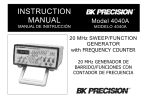
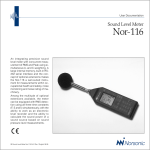
UNIVERSITY OF CYPRUS
DEPARTMENT OF COMPUTER
SCIENCE
CS 121 – DIGITAL SYSTEMS
LABORATORY
INTRODUCTORY TUTORIAL
LAB EQUIPMENTS
LAB INSTRUCTOR:
CHRYSOSTOMOS CHRYSOSTOMOU
SPRING 2001
CS 121 – DIGITAL SYSTEMS LABORATORY
INTRODUCTORY TUTORIAL
CS 121 – Digital Systems
Laboratory
Use of Lab Equipments
A. DIGITAL TRAINER – DT-01
You will be given a Digital Trainer (Figure 1). The DT-01 enables beginners
and advanced students to build and test circuits in a very short time, leading
to a rapid understanding of logic techniques. The built-in flexibility of the
solderless system means that circuits ranging from simple gates through
complex sequential logic can be developed.
Figure 1
The DT-01 provides a low cost method of prototyping circuit designs, which
can then be modified or extended with ease. The handy book-style case gives
complete protection to the circuit while in storage.
Prepared by Chrysostomou Chrysostomos
Department of Computer Science – University of Cyprus
1
CS 121 – DIGITAL SYSTEMS LABORATORY
INTRODUCTORY TUTORIAL
Features:
•
Logic probe included
•
Interconnection via solid 0.3mm ~ 0.8mm wire
•
Adjustable clock generator
•
9V 1A mains adapter provided
•
On-board 5V 750mA regulator
•
8 slide switches
•
2 bounce-free pushbutton switches
•
Two 4mm jacks provided
•
Two BNC connectors for linkup to test equipment
•
Sturdy book-style case
•
User manual included
Specifications:
Figure 2 explains the built-in accessories of the Digital Trainer.
1. AC ADAPTOR JACK: I/P DC + 8V 1.5A
2. PULSE SW.: Two bounce-free pushbuttons
Prepared by Chrysostomou Chrysostomos
Department of Computer Science – University of Cyprus
2
CS 121 – DIGITAL SYSTEMS LABORATORY
INTRODUCTORY TUTORIAL
3. LOGIC SW.: Eight logic level switches in DIP type.
4. DC O/P: DC + 5V, 750mA for user
5. B-023
BREADBOARD:
Solderless
bread-board
with
1580
interconnected tie points
6. CLIP TERMINAL: Logic probe clip terminal
7. LED DISPLAY: Eight LED buffered logic level indicators
8. BNC JACKS
9. SELECT SW.: Clock range selection.
L: 10 – 40 Hz
H: 1K – 20K Hz
10. BANANA JACKS
11. CLOCK ADJ.: Fine adj. of clock frequency.
Figure 2
PROVIDED FACILITIES
1. Power Supply
Input: The input supply will be supplied by AC Adaptor.
Output: The Digital Trainer has two parallel DC output ports by providing a
total DC power of +5V, 750 mA with an output short protection circuit.
How to select the input power:
Plug the DC jack of AC Adaptor into the black jack holder which is located
on the upper left corner of Digital Trainer, then plug the AC Adaptor into
the AC power outlet, you will then find the red LED power indicator is
lighting. It means that the system power is ready.
2. Pulses
The two independent de-bounced pushbuttons, called pulse switch P1, P2,
produce both the same positive-going 100ms pulse.
Prepared by Chrysostomou Chrysostomos
Department of Computer Science – University of Cyprus
3
CS 121 – DIGITAL SYSTEMS LABORATORY
INTRODUCTORY TUTORIAL
3. Logic switches
Eight logic level switches are provided in the form of an eight position
switch package, called DIP switch.
The output level is showing as follows:
L: Low, 0V
H: High, TTL compatible
4. Clock generator:
The frequency is adjustable between: 10 and 40 Hz on the L range, and
1K and 20K Hz on the H range.
5. LED display
Eight buffered logic level indicators are provided
6. BNC and BANANA connectors
Two 4mm BANANA connectors and two BNC I/O connectors are provided
for the external connection between this Digital Trainer and other
equipments such like OSCILLOSCOPE.
Adaptor Port No. 1. It presents the first BNC connector.
2. It presents the second BNC connector.
3. It presents the black BANANA connector.
4. It presents the red BANANA connector.
8. Logic Probe
The Logic Probe is provided as standard (Figure 3).
The portable Logic Probe is a versatile probe designed to measure logic
level such as TTL/CMOS and various kinds of ICs. It’s a perfect instrument
for troubleshooting and analysis of digital circuits.
With memory function, the pulse memory can detect the occurrence single
pulses or logic level. One shot, narrow pulses, which are nearly impossible
to be seen even with a fast scope, are easily detectable and visible. Its
memory function allows for indefinite storage of single shot.
Prepared by Chrysostomou Chrysostomos
Department of Computer Science – University of Cyprus
4
CS 121 – DIGITAL SYSTEMS LABORATORY
INTRODUCTORY TUTORIAL
Figure 3
Circuitry within the logic probe can examine the voltage at the point of
measurement and determine whether 0 or 1(Table 1). HI-LED (red) light
up indicates logic “1”, LO-LED (green) light up indicates logic “0”. The
PULSE-LED (yellow) enables one to observe a short-duration pulse that
would otherwise not be seen on the logic 1 and 0 LEDs.
The independent I/P power of this Logic Probe is supported by two fixed
gold clip terminals, which are located on the lower right corner of this
digital Trainer. The red alligator clip should be clipped to the positive side
of the power supply on the PC board under test. The black alligator clip is
to be clipped to the negative side of the power supply.
Logic
Input Level (TTL)
Display Light Up
0
< 0.8V
LO-LED (Green)
1
> 2.3V
HI_LED (Red)
Table 1
Prepared by Chrysostomou Chrysostomos
Department of Computer Science – University of Cyprus
5
CS 121 – DIGITAL SYSTEMS LABORATORY
INTRODUCTORY TUTORIAL
8. BreadBoarding
One model solderless breadboard is provided. The 1580 interconnected
tie points enable the users to make a practice without soldering. It
comprises of Distribution and Terminal strips (Figure 4 & Figure 5
respectively).
Figure 4
The Distribution strip is a 4-bus of 25 pre-connected tie point clip (every 25
points in a row are pre-connected -> horizontally connected).
Prepared by Chrysostomou Chrysostomos
Department of Computer Science – University of Cyprus
6
CS 121 – DIGITAL SYSTEMS LABORATORY
INTRODUCTORY TUTORIAL
Figure 5
The Terminal strip comprises of 128 groups of 5 pre-connected tie point
clip (every 5 points in column are pre-connected -> vertically connected).
Due to the different way of pre-connection of tie points (Distribution –
Terminal strips), BE CAREFULL how to make your connections in the
designed circuit. ALWAYS HAVE IN MIND THE HORIZONTAL AND
VERTICAL PRE-CONNECTIONS IN ORDER TO AVOID HAVING
SHORT-CIRCUITS IN YOUR CIRCUITRY!
WIRE CODING
For clarity of the way you design your circuitry, it is best to distinguish the
various parts, connected with wires, with different colour coding. A good
way to do so, is as follows:
Circuitry part
Wire coding
Supply
Red
Ground
Black
Inputs
Green
Outputs
Yellow
Inner-connections
Orange
Prepared by Chrysostomou Chrysostomos
Department of Computer Science – University of Cyprus
7
CS 121 – DIGITAL SYSTEMS LABORATORY
INTRODUCTORY TUTORIAL
INTEGRATED CIRCUITS (ICs)
You will be supplied with a Cutter Stripper Tool, a Whiteboard and a
Component Box with wires and the following ICs:
• 7400 x 2
• 7402 x 1
• 7404 x 1
• 7408 x 1
• 7420 x 2
• 7432 x 1
• 7447 x 2
• 7451 x 2
• 7475 x 2
• 7476 x 4
• 74289 x 1
•
SSDU x 2
A usual IC (e.g. 2-input NAND gate) is as shown below (Figure 6):
Figure 6
See Appendix A for details about all ICs (Data Sheets).
Prepared by Chrysostomou Chrysostomos
Department of Computer Science – University of Cyprus
8
CS 121 – DIGITAL SYSTEMS LABORATORY
INTRODUCTORY TUTORIAL
B. OSCILLOSCOPE
The oscilloscope is basically a graph-displaying device. It draws a graph of an
electrical signal. In most applications the graph shows how signals change
over time: the vertical (Y) axis represents voltage and the horizontal (X) axis
represents time.
An oscilloscope's front panel includes a display screen and the knobs,
buttons, switches, and indicators used to control signal acquisition and display
(Figure 7).
Figure 7
A signal is displayed when an oscilloscope probe is connected to a circuit.
You need to adjust three basic settings to accommodate an incoming signal:
•
The attenuation or amplification of the signal. Use the volts/div
control to adjust the amplitude of the signal to the desired
measurement range.
•
The time base. Use the sec/div control to set the amount of time per
division represented horizontally across the screen.
Prepared by Chrysostomou Chrysostomos
Department of Computer Science – University of Cyprus
9
CS 121 – DIGITAL SYSTEMS LABORATORY
INTRODUCTORY TUTORIAL
•
The triggering of the oscilloscope. Use the trigger level to stabilize a
repeating signal, or for triggering on a single event.
•
In addition, an oscilloscope has focus and intensity controls that can
be adjusted to create a sharp, legible display.
More precisely, the higher the voltage, the greater the vertical movement of
the display is. The grid on the face of the oscilloscope helps you measure the
amount of vertical movement of the display.
A vertical position control moves the "trace" up or down on the screen. With
the input switch set to "GND" (this grounds the input, making the input voltage
to the oscilloscope 0 volts) adjust the position so the trace is exactly in line
with one of the horizontal lines of the grid. This "baseline" is best positioned in
the centre of the grid.
Applying a positive voltage to the input of the oscilloscope will make the trace
will move up. Applying a negative voltage to the input of the oscilloscope
causes the trace to move down.
The space between two adjacent lines of the grid is called a "division". Each
major division is divided into five subdivisions. A control called the "volts/div"
switch sets the number of volts per division. For example, if the control is set
to 1 volt/div, then one volt applied to the tip of the oscilloscope probe will
make the trace move exactly 1 division. +1 volt will make the trace move up 1
division. -1 volt will make the trace move down 1 division. If the volts/div
switch on the oscilloscope is set for 2 volts/div, it requires 2 volts to move the
trace just one division. If the volts/div switch on the oscilloscope is set for 5
volts/div, it requires 5 volts to move the trace just one division.
There are two vertical inputs on the oscilloscope. They’re labelled channel 1
and channel 2. The vertical mode switch lets you select channel 1, channel
2 or both channels at the same time. The two channels allow the oscilloscope
to display two different signals.
Prepared by Chrysostomou Chrysostomos
Department of Computer Science – University of Cyprus
10
CS 121 – DIGITAL SYSTEMS LABORATORY
INTRODUCTORY TUTORIAL
The grid is divided into horizontal divisions just as it is divided into vertical
divisions. The oscilloscope shows you "time" in the horizontal direction. Just
as the vertical control sets the volts/div, the horizontal control sets the
seconds/div. At its slowest setting of 0.5 sec/div, the beam takes a full ½
second to cross just one horizontal division on the grid.
The next setting of the time-base speed is 0.2 sec/div. As we increase the
speed of the time-base, we decrease the amount of time required for the
beam to move a distance of 1 division. Now it takes just 0.2 sec for the
moving beam to pass each division. The next step up is 0.1 sec/div.; just onetenth of a second for each division. Since there are 10 horizontal divisions, it
takes 1 second to complete the trip from the left side of the screen to the right.
C. DIGITAL MULTIMETER
A multimeter (Figure 8) can be used for the majority of the various test and
measurements performed while repairing electronic circuits. Voltage, current,
and resistance can all be measured by the same unit, hence the name
"multimeter".
Measurements
such
as
these
are
often
the
key
to
troubleshooting and cannot be performed without help from the meter or a
similar piece of test equipment.
If the meter is to be of any use at all, it has to be connected to the circuit or
device to be tested. There are two test leads for the meter. One is coloured
red and the other is black. While the connection of each of the leads is totally
arbitrary for some tests, lead placement is critical for others so it's important to
install the meter lead correctly.
The black lead is connected to the meter jack marked "COM". This stands for
"common". The black meter lead will always be connected to the common
jack. As a reminder, there is a black ring surrounding this jack.
Prepared by Chrysostomou Chrysostomos
Department of Computer Science – University of Cyprus
11
CS 121 – DIGITAL SYSTEMS LABORATORY
INTRODUCTORY TUTORIAL
The red lead may be connected to any of three-meter jacks. There is a jack
on the meter marked "A" for "amperes" and another marked "10A" meaning
"10 amperes." The ampere (or "amp" for short) is the unit of measurement for
electric current. The red meter lead will be connected to either of these two
jacks if the meter is to be used for measuring current. Measurements of
voltage and resistance are where the digital multimeter is utilized most often.
For these tests, the red meter lead is inserted into the jack marked V-omega.
The Greek letter "omega" is used in electronics to denote resistance. The Vomega jack is marked with a red ring to indicate that this is the proper place to
install the red meter lead.
There are two types of voltage measurements that can be performed with the
meter. One is to measure the voltage of "direct current'' or DC. The other is to
measure the voltage of "alternating current" or AC. We will perform DC
voltage tests. DC voltage is measured with the meter set to "DCV".
Continuity tests
Testing to see if a wire is unbroken between two points is known as checking
the "continuity" of the wire. Continuity tests are performed with the meter set
to "beeper". Connectors are tested by connecting one meter lead to each side
of the suspect pin. A good connection makes the multimeter to “beep”.
Figure 8
Prepared by Chrysostomou Chrysostomos
Department of Computer Science – University of Cyprus
12
CS 121 – DIGITAL SYSTEMS LABORATORY
INTRODUCTORY TUTORIAL
APPENDIX A
DATA SHEETS
Prepared by Chrysostomou Chrysostomos
Department of Computer Science – University of Cyprus
13