1
Futek Advanced Sensor Technology – Futek VCal™Documentation
Rev. 1.8.0
07/26/05
Futek VCal™ Sensor Verification System
User’s Manual and Operating Instructions
Futek Advanced Sensor Technology – Futek VCal™ Documentation
Written by Futek Advanced Sensor Technology 
©Futek Advanced Sensor Technology 2005
1
Futek Advanced Sensor Technology – Futek VCal™Documentation
Rev. 1.8.0
07/26/05
Futek VCal™ Sensor Verification System – Table of Contents
I. About Futek VCal™
• System Features
• Calibration / Verification Features
• Quality Features
• Connections
• Service Agreement
• Technical Support
• VCal™ Accessories
• VCal™ Certified Auto Recognition Reference Sensor
II. Getting Started
• Getting To Know Your VCal™ System
•Power Face Plate
•Temperature Probe and Cable
•Sensor Face Plate
•VCal™ Identification Number Location
•VCal™ Overload Fuse Location
•Futek VCal™ Standard (CC1) Wiring Code
• Installation of Your VCal™ System
•Connecting Your VCal™ System
•Starting Your VCal™ System
•Removing Your VCal™ System
III. A Tour of Your VCal™ Environment
• Logging In To Your VCal™ System
• The Channel Display Windows
• Sensor Tab
• Filter Tab
• Functions Tab
• The Main Menu Toolbar
• The Display / Arrange Tool
• The RS232 Channel
• Setup Your Reference Sensor System
• Reference Sensor Options
• The Information Tabs Section
• The Sensor Tab
• The Setup Tab
• The Test Tab
• The Reference Sensor Test Grid
• The Calibration / Verification System
• The Information Tabs Section
• The Info Tab
• The Initial Tab
• The Setup Tab
• The Test Tab
• The Calibration Test Grid
• Futek Online
©Futek Advanced Sensor Technology 2005
***************** 4 - 6
***************** 4
***************** 4 – 5
***************** 5
***************** 5
***************** 5
***************** 6
***************** 6
***************** 6
***************** 7 – 19
***************** 7 – 9
***************** 7
***************** 7
***************** 7
***************** 8
***************** 8
***************** 9
***************** 10 – 13
***************** 13 – 15
***************** 16
***************** 17 – 19
***************** 20 – 39
***************** 20
***************** 21 – 22
***************** 21
***************** 21
***************** 22
***************** 22 – 39
***************** 22
***************** 23
***************** 24 – 28
***************** 24 – 25
***************** 26 – 28
***************** 26 – 27
***************** 27
***************** 28
***************** 28
***************** 29 - 33
***************** 30 – 33
***************** 30 – 31
***************** 32
***************** 32
***************** 33
***************** 33
***************** 34
2
Futek Advanced Sensor Technology – Futek VCal™Documentation
Rev. 1.8.0
07/26/05
Futek VCal™ Sensor Verification System – Table of Contents
• Vcal.net
• Calculators
• VCal™ Management Tools
• Send To Web
• Company Information
• The Backup / Restore Tool
• The User Management Tool
• Customer Information
• Manufacturer Information
• The Sensor Types Tool
• The Unit Conversions Tool
• The HV / Ohm Calibration Tool
• The Locations Tool
• The Load Direction Tool
• The Close Tool
• VCal™ Help
• The Electronic Data Sheet Tool
• Exit Management Tools
IV. Operational Instructions – “How To”
• Instructions For Calibrating Your Reference Sensor
• Introduction To Performing VCal™ Calibrations / Verifications
• Testing Modes
• Testing Options
• Testing Parameters
• Testing Conditions
• Calibration / Verification (Main Test)
• Calibration / Verification (Time Test)
• Calibration / Verification (Signature Test)
• Instructions For Performing Calibrations / Verifications
• Example: Calibration / Verification (Main Test)
• Example: Calibration / Verification (Time Test)
• Example: Calibration / Verification (Signature Test)
• Example: Applications – (Fixturing)
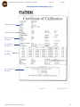
• Instructions For Printing A Calibration / Verification Certificate
• Example: Standard Calibration / Verification Certificate
• Instructions For Printing A Repeatability Report
• Example: Repeatability Report
V. Troubleshooting / Technical Support
VI. Futek VCal™ Specifications Page
VII. VCal™ Glossary of Terminology
©Futek Advanced Sensor Technology 2005
***************** 34
***************** 34
***************** 34 – 39
***************** 34
***************** 35
***************** 35
***************** 35
***************** 36
***************** 36
***************** 37
***************** 37
***************** 38
***************** 38
***************** 38
***************** 38
***************** 39
***************** 39
***************** 39
***************** 40 - 56
***************** 40 – 41
***************** 42 – 45
***************** 42
***************** 42
***************** 43
***************** 43
***************** 44
***************** 44
***************** 45
***************** 46 – 50
***************** 46 – 47
***************** 47
***************** 48
***************** 49 – 50
***************** 51 – 52
***************** 53 – 54
***************** 54
***************** 55 – 56
***************** 57
***************** 58
***************** 59 – 61
3
Futek Advanced Sensor Technology – Futek VCal™Documentation
Rev. 1.8.0
07/26/05
I. About Futek VCal™
Important: Please read
{If, during your reading, you come across words or terms which you are unfamiliar with, please check the Glossary we have provided. You can
find this Glossary at the end of this document, or by clicking this link. You may return to the Table of Contents from any page by clicking the
small VCal™ icon in the top corner of every page. Also, any references to page numbers llisted in blue are also links to those pages.}
System Features
1. The Futek VCal™ System comes equipped with an internal memory capability, which allows you to customize VCal™ to your own needs.
This capability allows for the storage of the data acquisition system and its related documents. It also allows for the storage of all of your
test data which can then be referenced later for print outs, certificates, signature checking, and for graphical analysis purposes.
2. The Futek VCal™ System supports Internet applications such as the remote management of your test data, test data backup &
retrieval, and for technical support and software upgrades.
3. The Futek VCal™ System features convenient ON/OFF and RESET switches.
4. The Futek VCal™ System offers the ease of ‘on the fly’ USB connections.
5. The Futek VCal™ System is very flexible and integrates easily into your current system by providing you a choice of either saving and
maintaining your test data in the VCal™ memory, or directly onto your PC.
6. The Futek VCal™ System offers a ‘user-friendly’ software and system environment, which requires no outside training. Easy to follow,
step by step instructions for installation and use are included in the VCal™ manual as well as online.
7. The Futek VCal™ System software supports one RS-232 channel (ASCII only).
Calibration / Verification Features
1. Includes (2) sensor inputs that support a full bridge input, and also includes a 5VDC-bridge excitation source.
2. Includes ± 20 bit Analog to Digital conversion of the sensor input.
3. Supports the use of sensors with amplified outputs (VDC or mA).
4. Offers software selectable, built-in Shunt Cal measurement, with scaling, for each input channel. Also supports external Shunt Cal resistors.
5. Offers built-in resistance measurement capability, which is useful as a bridge measurement tool or for troubleshooting sensors.
6. Offers sensor auto recognition capability (For sensors equipped with the Futek VCal™ Auto Recognition Chip).
7. Features built-in calculators for Zero Offset and Span adjustments, as well as a Unit Conversion calculator.
8. Offers additional features for troubleshooting strain-gaged sensors, and also for the revalidation of overloaded sensors.
9. Supports force, torque, and pressure types of measurements, as well as linearity, hysteresis, and repeatability testing with user-defined
load points.
10. Supports multi-component sensor testing with crosstalk check capability.
11. Supports either an automated or a manual test input.
©Futek Advanced Sensor Technology 2005
4
Futek Advanced Sensor Technology – Futek VCal™Documentation
Rev. 1.8.0
07/26/05
12. Supports calibration records with multiple ranges for reference sensors. Also allows you to manually enter test data from
a previously calibrated reference sensor.
13. Provides 3rd Order real time curve-fitting capabilities (Linearization).
14. Provides built-in, user-definable overload warnings, log reports, and recalibration date alarms.
15. Offers user customizable print outs, reports, and certificates.
16. Utilizes calibration methods that support ASTM Standards E4, E74-00a, ANSI/NCSL Z540, ISO Standards 17025, and 9001:2000, and
follows practices and procedures that are recommended by organizations such as A2LA and NVLAP.
Quality Features
1. Your stored test and calibration data is exportable to spreadsheet applications like Microsoft Excel for data analysis and graphing functions.
This aids in process control analysis, process and product performance analysis, and for meeting quality system statistical analysis
requirements.
2. Offers features that aid in the management of reference sensors; (1) support of multi-range calibration records, (2) allows manual entry of
test data from previously calibrated reference sensors, (3) provides 3rd Order, real-time polynomial linearization of reference sensors.
3. Offers built-in, user-definable overload warnings and log reports which aid in the documentation and control of nonconforming products
and built-in, user-definable recalibration alarms which aid in the control of planned calibration interval programs for reference sensors.
4. Utilizes methods, and provides tools for support of the following Quality Standards; ASTM E4 and E74, ANSI/NCSL Z-540, ISO 17025 and
9001:2000. Follows practices recommended by organizations such as A2LA and NVLAP.
5. Provides a clear audit trail for Reference Sensor traceability.
Connections
1. Includes (1) 15 VDC / 2A power supply connection.
2. Includes (1) 4-terminal connector block for I/O port connections.
3. Includes (2) sensor inputs.
4. Includes (1) temperature input connection.
5. Provides (2) LEMO quick-disconnect receptacles for sensor connections that utilize mV/V outputs, and (2) screw terminal connector
blocks for sensors that utilize amplified outputs.
6. Includes (1) 4-terminal connector block for external Shunt resistor connections.
7. Includes (1) USB connection.
Service Agreement
The Service Agreement includes; software upgrades and support, on-line data management access, VCal™ annual NIST traceable calibration
and system check, data transfer and storage on VCal™ Server at Futek Advanced Sensor Technology, and a membership to the VCal™ User
Group. Please contact Futek Advanced Sensor Technology for more information and details.
©Futek Advanced Sensor Technology 2005
5
Futek Advanced Sensor Technology – Futek VCal™Documentation
Rev. 1.8.0
07/26/05
Technical Support (The following features are available at the vcal.net web site - www.vcal.net).
1. On-line data management support.
2. Capability to review and/or print data reports or certificates via the Internet.
3. Store all test records and log all sensor overloads.
4. Easily monitor and manage upcoming recalibration due dates for your sensors.
5. On-line software upgrades and support.
Futek VCal™ Accessories
1. A Futek VCal™ Accessory Checklist is available online at the vcal.net web site in either HTML or PDF formats, or you may contact
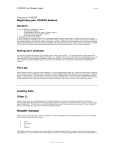
Futek VCal™ Certified Auto Recognition Sensor
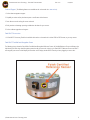
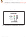
The following picture shows the Futek VCalTM Certified Auto Recognition Reference Sensor, all Certified Reference Sensors will feature the
label bearing the VCalTM logo. Auto Recognition means that all you have to do is plug in your Futek VCal™ Reference Sensor and VCal™
will recognize your sensor and will display its ID number on the Display window of the Channel you have plugged your sensor into.
©Futek Advanced Sensor Technology 2005
6
Futek Advanced Sensor Technology – Futek VCal™Documentation
Rev. 1.8.0
07/26/05
II. Getting Started
Getting To Know Your VCal™ System
Power Face Plate
I/O Connections
Power LED
Fuse Power Rating
DC Power Supply
ON/OFF Switch
USB Connection
{Temperature Probe Part # F-4569 / FSH01538}
Temperature Input
Reset Switch
{Temperature ExtensionCable Part #PK-10201 / FSH01537}
We are in the process of transitioning to a new system of Stock numbers for our inventory; for your convenience both are given when
listing model or part numbers in this manual. Older numbers are in black and newer numbers are in blue.
Sensor Fade Plate
Ch. 1 Amplified
VDC or mA Sensor
connection*
Ch. 1 Strain Gage
Sensor Connection
Exiteral Shunt Cal
Connection
Ch. 2 Amplified VDC
or mA Sensor
connection*
Ch. 2 Strain Gage
Sensor Connection
Note: You may notuse the Channel 1 strain gage Connection and the Channel 1 Amplified connection at the same
time. You may utilize a mV/V connection and an amplified connection at the same time, however; one must be
connected to Channel 1 and one connected to Channel 2. When using either of the Amplified Sensor connections;
*Please ensure that the exposed sections of sensor jumper wires do not contact each other.
©Futek Advanced Sensor Technology 2005
7
Futek Advanced Sensor Technology – Futek VCal™Documentation
Rev. 1.8.0
07/26/05
VCal™ Identification Number Location – Also displayed on Channel Display Screens when you are logged into VCal™
VCal™ Overload Fuse Location
©Futek Advanced Sensor Technology 2005
8
Futek Advanced Sensor Technology – Futek VCal™Documentation
Rev. 1.8.0
07/26/05
Warning! – Your Futek VCal™Reference Sensor comes equipped with an ID Auto Recognition Chip. Please do not apply power to this
chip or you may seriously damage it. Your Reference Sensor should only be connected to your Futek VCal™ unit, Futek accepts no
responsibility for any damage to ID Recognition Chips that are damaged in this manner.
Below is the Futek VCal™ Standard Wiring Code (CC1 Wiring Code)
The Futek VCal™Certified Auto Recognition Reference Sensor will support the IEEE 1451.4 Standard in the near future.
©Futek Advanced Sensor Technology 2005
9
Futek Advanced Sensor Technology – Futek VCal™Documentation
Rev. 1.8.0
07/26/05
Installation of Your VCal™ System
We recommend installing your VCal™ from the included installation CD; however you may also install from the VCal™ module.
From CD: If you have AutoPlay enabled simply plug in and follow the instructions on the screen. If not, you will need to open your CD
drive and run the Setup program from there. From VCal™: You will need to open the Removable Disk that VCal™ created, open the
Setup Folder, and run the VCal.msi installation program. Either method will work equally well; whichever method you use, please note
the following:Minimum Requirements: It is recommended that your VCal™ be installed on a PC running either Windows 2000 or
Windows XP; and with a Pentium II, 400 MHz or better, with an available USB port, and with a screen resolution of 1024 x 768, 256
colors, MDAC 2.7 (available at www.microsoft.com), all the latest service releases and updates (both critical and Windows) for you
roperating system, 100 MB of free disk space. You are also responsible for your PC’s hardware and BIOS updtaes and drivers.
The exact screens you will see after starting the installation CD will vary depending on your PC system’s setup and configuration.
However, no matter what your operating system or configuration they should all progress through the following steps in one form or
another.
Note: Windows XP users may encounter a message regarding Windows Logo Testing and incompatibility: we ask that you
please disregard this message and continue with the installation. We are in the process of working this issue out.
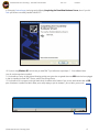
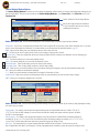
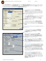
1. First you should see the Futek Vcal™ Installation opening screen...
2. Clicking Next brings up the Welcome to VCal™ Setup screen...
©Futek Advanced Sensor Technology 2005
10
Futek Advanced Sensor Technology – Futek VCal™Documentation
Rev. 1.8.0
07/26/05
3. Clicking Next brings up the License Agreement screen…
4. If you first select I Agree, and then Next, you will see the Select Installation Folder screen…
VCal™ will by default install to C:\Program Files\VCal\…, if this will work for your computer’s setup then simply click Next. If this will
not work for your computer’s setup then you may Browse and select the Drive and Folder that will work for you, and then click Next; or
click Previous to return to a previous screen and change a setting, or click Cancel to exit the Installation program.
©Futek Advanced Sensor Technology 2005
11
Futek Advanced Sensor Technology – Futek VCal™Documentation
Rev. 1.8.0
07/26/05
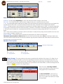
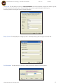
5. Clicking Next, brings up the Confirm Installation Screen . . .
6. If you are satisfied with the Installation settings you have chosen, then click Next. If not, then click Previous to return to a previous
screen and change a setting, or click Cancel to exit the Installation program. Clicking Next will bring up the Installing VCal™
screen…
©Futek Advanced Sensor Technology 2005
12
Futek Advanced Sensor Technology – Futek VCal™Documentation
Rev. 1.8.0
07/26/05
7. Once the installation is complete you will see the Installation Complete screen, simply click Close here and your VCal™
installation is complete!
Connecting Your VCal™ System
Now that you have successfully installed your Futek VCal™ system, it is time to connect your VCal™. Futek VCal™ is very simple to
connect. For best results we recommend that you connect your VCal™ in the following manner; Please note the General Safety precautions listed on (page 57) before connecting your VCal™.
1. Plug in the DC Power Supply (included with your VCal™) into the wall outlet and then into your VCal™ unit.
2. Push in the ON/OFF power button, the red power LED should light.
3. Plug the USB cable (included with your VCal™) into the USB outlet on your PC
4. Plug the USB cable into your VCal™ unit, and plug your Temperature Probe into the connector on the
Power Face Plate.
5. Your Futek VCal™ unit is now connected.
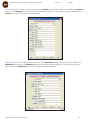
6. After connecting your VCal™ you should first see the Found New Hardware Screen...
©Futek Advanced Sensor Technology 2005
13
Futek Advanced Sensor Technology – Futek VCal™Documentation
Rev. 1.8.0
07/26/05
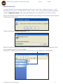
7. Clicking Next, brings up the Choose Driver Screen, please choose to search Removable Media {CD…}
8. Some Windows XP users may encounter the following Incompatibility message; Please disregard and continue…
©Futek Advanced Sensor Technology 2005
14
Futek Advanced Sensor Technology – Futek VCal™Documentation
Rev. 1.8.0
07/26/05
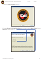
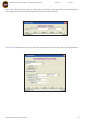
9. Clicking the Continue Anyway icon brings up the following Completing the Found New Hardware Screen, where if you click
Finish you will have successfully installed Futek VCal™!
10. If you are using Windows XP, the first time you install VCal™ you will need to repeat steps 6 – 9 two additional times
(once for each storage device installed).
11. You should see a series of dialog boxes informing you that your system has recognized that a new USB device has been plugged
in, that it is installing the Futek VCal™ Device, and the Mass Storage Device.
12. You should see an icon appear in the right hand side of the taskbar at the bottom of your screen, which indicates that an USB
piece of hardware is installed, and which allows you to safely unplug or eject the hardware. (An icon with a green arrow).
©Futek Advanced Sensor Technology 2005
15
Futek Advanced Sensor Technology – Futek VCal™Documentation
Rev. 1.8.0
07/26/05
To Start Futek VCalTM
Now that you have successfully installed and connected your Futek VCal™ system, it is time to start VCal™. To do this you will need
to open the Removable Disk that VCal™ has installed, and to do this you will need to open your My Computer folder. If you have a
shortcut to your My Computer folder on your desktop you may simply double click on this; or you can open your Windows Explorer
and you will find My Computer, or you can open your Start Menu and find My Computer. Use whichever method is easiest for you;
regardless of how you do it, once you open My Computer...
You will see that Futek VCal™ has installed a ‘Removable Disk’ on your computer. What is already installed on your computer will
determine what drive letter VCal™will assign to this ‘Removable Disk’, but for most systems it will probably be assigned the letter
E:. Double clicking this Removable Disk icon will bring up the following screen…
You may now double click the VCal™ icon to start Futek VCal™, or you may click and drag the icon onto your desktop to create a convenient
Shortcut to VCal™.
©Futek Advanced Sensor Technology 2005
16
Futek Advanced Sensor Technology – Futek VCal™Documentation
Rev. 1.8.0
07/26/05
Removal of Futek VCal™
To remove Futek VCal™ from your system you may either go to My Computer Control Panel -->Add Remove Programs --> VCal™
OR you may go to My Computer -->Removable Disk E: -->Setup -->Setup -->VCal™ (this way provides an option for repairing the
installation configuration settings). Either of these methods will work. First, the method which uses Add Remove Programs:
When you click on the Remove button under VCal™ in the Add Remove Programs window you are first asked to confirm that you wish
to that you wish to remove VCal™:
Clicking Yes will bring up the Removal Progress Bar window . . .
When this removal process finishes you will see the VCal™ listing disappear from your list of currently installed programs, and you
have successfully removed VCal™ from your computer.
Using the VCal™ installation program to remove VCal™; once you click on the VCal installation icon in the Setup folder:
©Futek Advanced Sensor Technology 2005
17
Futek Advanced Sensor Technology – Futek VCal™Documentation
Rev. 1.8.0
07/26/05
You will first see the VCal™ Logo Screen, clicking Next . . .
Will bring up the Welcome To The Setup Wizard Screen, where you are given the option to Remove or Repair. Choosing to
Remove VCal™ and then clicking Finish . . .
©Futek Advanced Sensor Technology 2005
18
Futek Advanced Sensor Technology – Futek VCal™Documentation
Rev. 1.8.0
07/26/05
Will bring up the Removing VCal™ Progress Bar Window . . .
Followed by the Installation Complete Screen when the process is finished. If you will click on the Close button you will have
successfully removed VCal™ from your computer.
©Futek Advanced Sensor Technology 2005
19
Futek Advanced Sensor Technology – Futek VCal™Documentation
Rev. 1.8.0
07/26/05
III. Tour of The VCal™ Environment
Logging In To Futek VCalTM
Now, you have installed the VCal™ software, you have connected VCal™ to your computer system, and you have learned how to start
your VCal™ system. Now it is time to Log in to VCal™ and get started. When you double click the VCal™ icon in the Removable Disk
E: or on the shortcut to VCal™ which you created earlier on your desktop, you will see the VCal™ Log In Screen . . .
The first time you log in to VCalTM you will need to use the Futek factory provided password to log in (located on
the silver label on the bottom of your VCal™, next to the VCal™ ID Number). Once you have logged in the first time you may go to
Management Tools (see pgs. 34 - 39) and set up your usernames and passwords to suit your application. Once you have entered
your username, password, and clicked OK, you will briefly see the Initializing and Detection Screen . . .
Followed by the VCalTM Main Screen, which contains the Main Menu Toolbar and the Channel Display Windows . . .
Main Menu Toolbar
Channel Display
Windows
©Futek Advanced Sensor Technology 2005
20
Futek Advanced Sensor Technology – Futek VCal™Documentation
Rev. 1.8.0
07/26/05
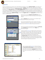
Channel Display Window Options
The Channel Display Windows are where your test readings are displayed, and also where you set your initial configuration settings for your
tests and verifications. There are three main tabs to the Channel Display Windows; (1) the Sensor Tab; (2) the Filter Tab; and (3) the
Functions Tab:
Hide or Unhide the Channel Display Window
You may also drag and drop the windows to
to any convenient location on the screen by
grabbing the blue title bar.
Under the Sensor Tab - You will find the following tools and command buttons (from left to right, and top to bottom):
ID Input Box - If your sensor is equipped with the Futek VCal™ auto-recognition ID chip the sensor serial number will appear here, or you may
enter a sensor serial number here manually. The checkbox allows you to select/unselect the Auto Read function. (pg. 32)
BRDG - Bypass ID-Chip Polling: Use when calibrating reference sensors with no ID chip.
CAP - This box lets you enter a capacity for the sensor you are testing or verifying on this channel.
Clear the Scaling - Clears any scaling factor which may currently be loaded. Used for creating a new calibration curve for calibrating your
Reference Sensors.
Tare - The zeroed reading of your sensor with all offsets nulled.
Gross - The untared reading of your sensor with all offsets still in place.
Set to Peak Mode - Takes a peak reading, unselect to clear the peak reading.
Set to Valley Mode - Takes a valley reading, unselect to clear the valley reading.
mV/V - Shows you the current mV/V reading of the sensor without clearing the scaling factor, used to verify that mV/V matches load.
DEC - Allows you to define the decimal places displayed.
F / C - Allows you to define whether test temperature is displayed in Fahrenheit or Celsius.
Loading Speed - Allows you to monitor and subsequently control, the speed with which your load, and thus output, changes.
UNITS - Allows you to change the displayed units in real time.
Under the Filter Tab - You will find the following available settings, which you may customize to your needs by simply adjusting the sliding
bars to the value you require.
Sampling Rate - This setting is used to adjust the internal sampling rate, the eight available rates are: 4.688; 9.375; 18.75;
37.5; 75; 150; 300; and 600 readings per second. Please note that filter settings and system overhead in general, will affect
the VCal™ actual throughput.
Filter Frequency - This setting is used to adjust the frequency of the low pass filter. On Standard Filter the following settings are
available: 40; 18; 8; 4; 2; 1; 0.5; and 0.25 Hz. On Fast Recovery Filter the following settings are available: 18; 11; 9; 7; 5; 4; 3.5;
3; and 2.5 Hz. The filter setting determines how fast the system will respond to changes in load.
Filter Type - This setting allows you to choose between Standard and FIR Fast Recovery filters. Transient recovery of this
filter is independent of the filter’s cutoff frequency. The filter setting determines how fast the system will respond to changes in load.
©Futek Advanced Sensor Technology 2005
21
Futek Advanced Sensor Technology – Futek VCal™Documentation
Rev. 1.8.0
07/26/05
Under the Functions Tab - The following command buttons are available:
HV OFF/ON - This button toggles High Voltage off and on, which determines whether reading is in mV/V or Volts
R IN / R OUT - These buttons take input / output resistance readings from the sensor connected to the chosen channel.
V / mA - This button toggles between voltage and mA readings. Please note that electrical connections for voltage and current are separate. Also
note that when HV is ON, no VCal™ sensor will be detected, and that ‘Clear Scaling’, mV/V, R IN, R OUT, and shunts will all be disabled.
INS-CAL - This button executes an internal calibration and compensation for the analog to digital converters (ADCs). This procedure compensates
for any changes in temperature and ensures that the instrument is in calibration. This procedure is automatically performed when the Reference
or Test Sensor tests are initialized. It is recommended that the INS-CAL be executed prior to taking readings when VCal™ is to be used as a
display.
RESET - Under normal circumstances you will never need to use this button. It is mainly for factory testing. It causes the ADCs to do a warm reset,
clears any tares, and initiates a calibration cycle.
SHUNTS - EXTERNAL - A shunt resistor must be connected to the shunt terminal, press ‘External’ to activate shunt.
Shunt button must turn yellow to indicate it is on. You must shut off any shunt buttons that are ON, before switching to another shunt
value. Please note that some shunt values will exceed your calibration range and produce undesired results. Please select shunt values which are
appropriate to the current range you are using.
Main Menu Toolbar Options
Main Menu Toolbar Options
Hide / Unhide The
Ch. 1 Display Window
Hide / Unhide The
Ch. 2 Display Window
Display / Arrange - This option provides you some ways to customize the look and function of the channel 1 & 2 displays. You can
drag and drop the displays to anywhere on your screen, by grabbing the blue, title bar at the top of the window with your mouse. You
can also hide the Sensor, Filter, and Functions tabs, leaving just the display itself, by simply clicking in the display portion of the window.
Please note that when the background of the display turns RED this indicates an “Over Load Condition”, and when the background of the
display turns YELLOW it indicates an “Over Range Condition.”
Please note that an “Over Range Condition”
indicates a load outside of the range of the sensor
is being applied and care should be taken.
An “Over Load Condition” is more severe (as
indicated by the red screen). This indicates that a
sensor is in a condition of Overload and is in danger
of being damaged.
©Futek Advanced Sensor Technology 2005
22
Futek Advanced Sensor Technology – Futek VCal™Documentation
Rev. 1.8.0
07/26/05
RS - 232 Channel - This option allows you to access the RS - 232 channel, where you can then connect ASCII devices to your VCal™
system, such as the Futek D502, D506, and D526 . . .
COM - Allows you to designate which communication port you wish to use (COM’s 1 – 16 are available).
Baud - Allows you to designate the baud rate you wish to use (300 – 115200 are available).
Parity - Allows you to choose between Non, Odd, or Even parity checking.
Char – Allows the user to choose between 7 or 8 character.
Stop Bit - Allows you to choose either 1 or 2 as your stop bit.
Handshaking - Allows you to choose between None, XonXoff, RTS, and RTSXonXoff as your handshake method.
Termination Characters - Allows you to define termination characters for strings received from, or transmitted to the device.
RX Data Command - Allows you to define data commands received from the device.
Profile - Allows you to enter and save commonly used profiles, so that they may be easily used later.
Misc. Commands - Allows you to define commonly used commands that are transmitted to the device.
©Futek Advanced Sensor Technology 2005
23
Futek Advanced Sensor Technology – Futek VCal™Documentation
Rev. 1.8.0
07/26/05
Setup Reference System - This option allows you to enter and setup Reference Sensor Information and Records, and to
calibrate your Reference Sensors. When you click the Reference Sensor button, it brings up the following Reference Sensor screen . . .
Reference Sensor Options First off, there is a row of command buttons near the top left corner of the screen that should be familiar to anyone familiar with Windows. . .
Clear - This option allows you to Clear currently loaded Reference Calibration information.
Open - This option allows you to manage your saved Reference Cell records by providing you the options to Load, Delete, or Close
any saved Reference Cell record
Save - This option allows you to Save the currently loaded Reference record (If there are existing records under the same serial number
you are asked if you wish to Create a New Record, Write Over the Existing Record, or Cancel the Save action)…
©Futek Advanced Sensor Technology 2005
24
Futek Advanced Sensor Technology – Futek VCal™Documentation
Rev. 1.8.0
07/26/05
Help - This option allows you to access this User Manual.
Exit - This option allows you to Exit the Reference Calibration interface of Futek VCalTM .
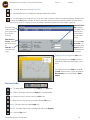
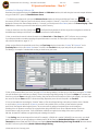
Plot - This option allows you to create 3D Graphs of your test results, or export your data to a spreadsheet application. Clicking the Plot
icon brings up the Plot interface. Here you can load your saved tests, determine which tests should be included in your plot, and then
either Generate your VCal™ 3D graph, or export your data to a spreadsheet application for further analysis or graphing.
Select which test
results you would
like to create Graphs
of by selecting
check box
Show Tests for
Current - all saved
tests under current
ID
Show All - all
saved tests under
any ID
Autoscale Check
Box - Automatically scales Y axis
based on given
values. Uncheck
to enter custom
values.
Select either Generate Plot (to
view Graph) or the
Export button to
send the data to a
spreadsheet
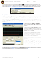
Clicking Generate Plot brings up this Plot screen . . .
Here, each colored line in the Graph represents a
separate set of test results chosen from the screen
above.
The bottom, or x-axis in this Graph represents %
of Load, while the vertical, or y-axis represents the
Non-Linearity error as a percentage of Rated
Output.
Plot Screen Toolbar
Print - This button allows you to print the current Graph(s) in the Plot screen.
Orbit - Creates a 360 Degree orbit of the plot Graph(s) in a separate window.
Zoom - Allows you to zoom in and out of the current Plot screen.
Pan - Allows you to pan left to right or up and down withing the Plot screen.
Restore - This button restores the default Graph view
Show Text - This option creates markers indicating point values on the Graph(s).
Close - Closes the Plot screen.
©Futek Advanced Sensor Technology 2005
25
Futek Advanced Sensor Technology – Futek VCal™Documentation
Rev. 1.8.0
07/26/05
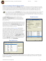
The rest of the Reference Sensor Calibration interface is broken into two, basic sections; the Information Tabs, and the
Test Grid sections . . .
Information Tabs Section
Test Grid Section
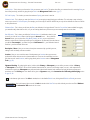
Information Tabs Section - There are three main windows to the Information Tabs Section . . .
First is the Sensor Info tab; this is where you will enter the descriptive information on the Reference Sensor you are calibrating. Please note that
Text Box Titles which are displayed in Blue are required if you wish to perform a calibration or test.
Manufacturer - This is where you enter the name of the
manufacturer of the load cell you are calibrating. Clicking the down
arrow icon at the right of the text box displays a pull - down menu
which lists all Manufacturers you have saved in the Management
Tools section of VCal™. (see pg. 36) Clicking the icon with three
periods will talke you to the section of Management Tools where you
save Manufacturer Names.
Model - This is where you enter the Model number of your sensor.
Sensor Type - This is where you enter the type of sensor you wish to
test or calibrate. Again, you have icons for accessing the pull - down
menu of saved sensor types, and for going to the Sensor Types in the
Management Tools section of VCal™. (see pg. 37)
Serial Number - This is where you enter the Serial Number of the
reference sensor you wish to calibrate.
Channel/Bridge - This is where you enter the Channel or Bridge you
wish to use (on multi-channel sensors) Default is 1.
Load Direction - This is where you specify which Direction you wish to
apply your load in. Again, there are icons for accessing the pulldown
menu of saved Load Directions and for going directly to the saved load
direction Units in the Management Tools section.(p. 38)
Full Scale Capacity - This is where you enter the Full Scale Capacity (max load) for your sensor. Again, there is the familiar, pull-down menu of
saved load units, and an icon for going directly to the saved Conversion Factors in the Management Tools section. (p. 37)
Calibration Load - This is where you designate the Maximum Load you wish to apply during this test. Please note that this amount may or may
not be the same as the Full Scale Capacity for your sensor. Again, there is an icon for the pull-down menu for Load Units, and also for 26 decimal
places in the Calibration Load values.
©Futek Advanced Sensor Technology 2005
26
Futek Advanced Sensor Technology – Futek VCal™Documentation
Rev. 1.8.0
07/26/05
Loading Points - This is where you enter the number of Load Points you wish to include in your test. Default is 5 points.
Calibration Date - This where you enter the Date of your test. If you are entering data from a previous test you may enter the date manually. If you
are performing the test now there is a convenient button for entering the current date with one click.
Next Calibration Date - This is where you define the Calibration Interval for your sensor. You may enter a date manually, or you can click the
Interval button to bring up a window where you can define Interval in terms of Daily, Weekly, Monthly, or Yearly.
Description / Notes - Here you can enter a brief Description or Notes to help you label or differentiate your tests (maximum 50 characters).
NIST Number - Here you can enter the NIST traceability number for your test.
Locations - Here you can enter the Location where your test took place. Once again, there is an available pull-down menu to quickly access
previously saved locations, as well as an icon for going directly to the Location section of Management Tools. (p.38)
Refresh - You can use this button to reload or Refresh your screen.
Next Tab - This button allows you to move to the next tab (Example: from Sensor Info to Test Setup). You can also click on
the tab title to move to that tab.
The next window under the Information Tabs is the Test Setup tab. This is where you define/document the conditions for your Test. . .
There are three main divisions to the Test Setup Tab;
The first is the Environmental Conditions Window Here you can manually enter readings for temperature
and humidity from your external sensors; OR you can
use the Futek VCal™ temperature probe and click Get
Reading and VCal™ will take and enter a value for you.
The next main division is the Test Parameters Window Here you can enter an Averaging Value, this number tells
VCal™ how many readings to take, and then return the
value which is the Average of these readings.
The last division under the Test Setup Tab is the Test
Conditions Window - Here you define whether you wish
to test for Linearity OR Linearity and Hysteresis; and also
whether you wish to enter your Data Manually, or let
VCal™ take and enter your Verification readings. There
is also an Initialize Test Button when you are ready to
start your test, and the Arrow Button to take you to the
next tab when you are ready.
©Futek Advanced Sensor Technology 2005
27
Futek Advanced Sensor Technology – Futek VCal™Documentation
Rev. 1.8.0
07/26/05
The final window under the Information Tabs Window
- is the Test Tab Window. This window provides you
some options for applying correction factors and
uncertainty values to your test to provide added
confidence in the accuracy of your results.
The Corrections section of this window is where
you can view the Linearization Coefficients and
Uncertainty Values for your calibration. Once you
have completed a test you can come to this tab
and click the Linearize Button to view these values.
Please note that Hysteresis Correction values will
only be calculated if Hysteresis was selected on the
Test Setup Tab under Test Conditions.
The Scaling section of this window is where you
can set Over Load and Over Range warning points,
as well as set Scaling Factors. You simply enter the
Rated Output of your sensor, load to the desired
calibration load, take a current output reading,
and then press Scale To Unit (more detail will be
given in the Instructions section). The number of
decimal points for pre-calibrated reference sensor
output can be entered in the Output Decimal Points
textbox.
Calibration Test Grid
The other half of the Reference Sensor interface
is
The C alibration Test Grid.
The Data Acquisition Channel is the channel you
have your Reference Sensor connected to.
The Test Grid is where you will perform your tests
and view your test results.
The Tare Button allows you to utilize offsets and
zero the unloaded output.
The Gross Button allows you to take an untared
reading with all offsets in place.
©Futek Advanced Sensor Technology 2005
28
Futek Advanced Sensor Technology – Futek VCal™Documentation
Rev. 1.8.0
07/26/05
Calibration / Verification - This option allows you to access the following interface used for calibrating and verifying sensors . . .
Once again, there is the familiar looking row of command buttons across the top of the interface . . .
New - This option allows you to create a New calibration record.
Load - This option allows you to Load a previously saved calibration record.
Save - This option allows you to Save the currently loaded record.
Print - This option allows you to Print a saved calibration record. (See page 25 for details.)
Polynomial - This option allows you to view the Polynomial coefficients for the current calibration
Plot - Graph the results of a saved calibration record.
Test - This option allows you to choose from three types of test; Main Test, Time Test, and Signature Test (see Calibration instructions for
details on these tests pgs. 40 - 56).
Help - This option allows you to access this User Manual.
Exit - This option allows you to Exit the Sensor Calibration interface.
©Futek Advanced Sensor Technology 2005
29
Futek Advanced Sensor Technology – Futek VCal™Documentation
Rev. 1.8.0
07/26/05
The rest of the Calibration / Verification interface is (like the Reference Sensor interface) divided into two main sections; the Information Tabs
section, and the Test Grid section . . .
Information Tabs Section - Under the Information Tabs section there are four tabs; Info, Initial, Setup, and Test . . .
First is the Info Tab, this is where you will enter the descriptive Sensor Information for your test. Please note that Text Box Titles which are
displayed in Blue are required information if you wish to perform a calibration or verification.
Manufacturer - This is where you will enter the name of the Manufacturer of
the load cell you are calibrating or verifying. Again (as in the Reference Sensor
interface) the icon with the down arrow just to the right of the text box,
will bring up a pull-down menu of the Manufacturer names you have saved in
the Management Tools section, and the icon with the three periods will take
you to the section of Management Tools where you save Manufacturer Info.
Model - This is where you will enter the Model Number or Model Name of the
sensor you are calibrating.
Sensor Type - This is where you will enter the Type of sensor you are
calibrating. Again, there are the down arrow and three period icons for
entering saved Sensor Types and for going directly to the Sensor Type section
of Management Tools. (pg. 37)
Serial Number - This is where you will enter the Serial or ID Number of the
sensor you are calibrating.
PO - This is where you will enter the Purchase Order number if applicable to your situation.
Customer - This is where you will enter the name of the Customer for whom you are performing the calibration. Once again there are icons
available for accessing saved customers and for going to Management Tools. ( pg. 37)
Channel / Bridge - This is where you will enter which Bridge ( on multi-channel sensors) you are calibrating (default is channel 1).
Load Direction - This is where you will enter which Direction you wish to apply your Load in (Compression, Tension, CW, CCW, etc.). There are again
the icons available for accessing your saved load directions, and for going to Load Direction in the Management Tools section.(pg. 38).
©Futek Advanced Sensor Technology 2005
30
Futek Advanced Sensor Technology – Futek VCal™Documentation
Rev. 1.8.0
07/26/05
Loading Units - This is where you wil enter the Units you measure your Load in. This option also offers you command icons for accessing Units you
have saved previously, and also for going directly to Units in the Management Tools section. (pg. 37)
Full Scale Capacity - This is where you enter the maximum Capacity your sensor is rated at.
Calibration Load - This is where you enter the Maximum Load you are going to apply during your calibration. This value may or may not be the
same as your sensor’s Full Scale Capacity. For example, your sensor may be rated at 1000 lbs but you only wish to calibrate the sensor to 500 lbs
on this particular test.
Calibration Date - This is where you will enter the Date your calibration is being performed. There is a Current Date button available for tagging
your test with today’s date with one click, or if you are entering data from a previous test you can manually enter the correct date.
Next Calibration - This is where you define the Calibration Interval (recalibration date) for your
sensor. If you click the Interval button it will bring up the Interval screen . . .Here, under the
Interval column, you can select from Daily, Weekly, Monthly, or Yearly as your main Interval
definition; and under the Sub-Interval column you can designate an incremental of the main Interval
you defined. For example; if you Select Yearly and a Sub-Interval of 1, your Calibration Interval
would be 1 year from the date of the test.
Description / Notes - Here you can enter a descriptive comment to help you label your test,
making it easier to identify and more traceable.
Location - Here you can record the name of the department or Location where your test was
performed for future reference and as a documentation aid. There are the now familiar icons for a
pull-down menu of saved Locations, and for going directly to the Location section of Management
Tools. (pg. 38)
Signature Checking - By selecting this option (and also either Primary or Subsequent) you can define your test as either a Primary
or Subsequent test, and VCal™ will record the standard characteristics of your test (non-linearity, output, error, etc), and compare these
characteristics against any Subsequent tests performed under identical test situations and conditions and using the same processes and
procedures as in the Primary test. More details will be given on Signature testing in the Instructions for Calibrating and Verifying section
on pgs. 45, 48.
In the bottom, right corner of the Info tab window, there is the familiar Refresh icon, clicking this will Refresh or Reload your screen.
Also in the bottom, right corner of the Info tab window is this Next Tab icon, which will take you to the next Tab or Window in
the Information Tabs section of the screen.
©Futek Advanced Sensor Technology 2005
31
Futek Advanced Sensor Technology – Futek VCal™Documentation
Rev. 1.8.0
07/26/05
The next Tab or Window under the Information Tabs section of the Calibration / Verification interface is the Initial Tab, where you will do
the Initial setup for your test: Record Environmental conditons, perform Shunt Calibration with either the built-in Shunt values,or with your
own, external shunt resistors, and also take and record Bridge Resistance readings.
The first section of the Initial tab is the Environmental
Conditions section; here you can enter and record the relative
humidity levels and leakage factor for your test, as well as obtain
and record the temperature in either Fahrenheit or Celsius from
your VCal™ temperature probe.
Next is the Shunt Calibration section; here you can use VCal™’s
built in Shunt values or select External and connect your own
shunt resistors to VCal™, and obtain and record the Shunt
Calibration readings for your test.
The final section of the Initial tab is the Bridge Impedance
section; here you can obtain and record the bridgeresistance
for the sensor you are calibrating by clicking the Take Reading
Button
The Next Tab icon will move you to the next window, in this case, to
the Setup Tab . . .
The Setup Tab is where you can define the Testing Mode,
your Test Options, the Test Parameters, and the Test
Conditions for your test.
Under Testing Modes you can choose between Normal,
Extrapolation, and Actual Modes of Testing. Descriptions
of these Modes will be given in the Calibration/Verification
Instructions section of this Manual. (pg. 42)
Under Test Options you can choose between either Manual
Entry, or Scaled Testing. More detail will be given on these
options in the Calibration/Verification Instructions section of
this Manual. (pg. 42)
Under Test Parameters you can define such parameters for your
test as Loading Points, Averaging, Decimal Points, and Target
Load Warning Tolerances. The Scaled Testing Decimal
Points textbox allows you to select output decimal points when
performing a scaled test. More details will be given on setting
these parameters in the Calibration/Verification Instructions
section of this Manual. (pg. 43)
Under Test Conditions you can define whether your test is
performed with VCal™ automatically taking readings at your
pre-determined load points, or whether you wish to read your
data from an RS232 device, and also whether you wish to test for
Linearity or Linearity / Hysteresis. There is also a button for
Beginning your test. (pg. 43)
©Futek Advanced Sensor Technology 2005
32
Futek Advanced Sensor Technology – Futek VCal™Documentation
Rev. 1.8.0
07/26/05
The final tab under the Information Tabs section of the Calibration / Verification interface is the Test tab. Here is where you obtain and
record your Offset readings (First and Final Unfixtured Zero Readings), and also where you will view the Uncertainty and Zero Return
values generated by your test results.
Under the Offsets section of the Test tab window is
where you will take your unfixtured zero readings,
both the First and the Final Zero Readings. To do
this you can either click into the text box next to the
Zero reading you wish to take and press Enter; or
you can click into the box and click on the Un-Fixtured
button to the right of the text box. Either way your
unfixtured zero reading will appear in the text box.
Under the Results section of the Test tab window is
where you will come to view the Uncertainty factor
calculated for your particular test results. This is
also where you will come to view the Zero Return
value as a percentage of Full Scale.
The Test Grid makes up the other half of the Calibration
/ Verification interface window.
Here is where you will define which Channel you have
connected your Reference Sensor to, and which you
have connected your Test Sensor to.
It is also where you will define which Units you want to
use to measure your Load and your Output.
This is the Test Grid where you perform your tests and
view your outputs.
There are also buttons available here for you to Tare
your display, take a Gross reading, and Cancel
the Current Test.
©Futek Advanced Sensor Technology 2005
33
Futek Advanced Sensor Technology – Futek VCal™Documentation
Rev. 1.8.0
07/26/05
Futek Online - This option allows you to connect directly to Futek’s web site (www.futek.com): Here you can make use of the many
resources available at Futek online. There are product catalogs, calculators, application solutions, and technical support options.
VCal.Net - This option allows you to access (www.vcal.net), where database management tools, software updates and upgrades,
record maintenance tools, and reference sensor maintenance tools are all available, as well as the HTML and PDF versions of this User
Manual.
Calculators - This option allows you to access the built-in calculator functions of VCal™. Below you will find a brief description of each of
the built-in calculator functions of VCal™:
Zero Balance Calculator: This calculator allows you to calculate the external resistance value required to bring the zero balance
within acceptable limits. You can enter the actual zero reading from the test in mV, the bridge resistance of the sensor, and the excitation
voltage, and the program returns the value of resistance needed in ohms. You can then enter the actual resistor value that you have on
hand, ( as close to the calculated value as possible) and VCal™ will return the zero value in mV for that resistance.
Span Adjustment Calculator: This calculator allows you to calculate the external resistance required to bring the sensor output
within an acceptable tolerance limit. You can then enter an actual output reading from the test in mV/V, enter the desired output in mV/V,
enter the input resistance of the bridge, and VCal™ will return the span resistor value required. You can then enter an actual resistor
value that you have on hand, and VCal™ returns the adjusted output.
Conversions Calculator: This calculator allows you to get immediate unit conversions in the following list of categories; Pressure, torque,
force, length, volume, temperature, Ratiometric, voltage, and current.
VCal™ Management Tools - This option allows you to acces VCal™’s array of Management Tools. The following outlines these tools:
Send To The Web - This feature allows you to transfer your test data to the Futek host server, where it is stored and available to you as a
resource management tool on the vcal.net web site.
©Futek Advanced Sensor Technology 2005
34
Futek Advanced Sensor Technology – Futek VCal™Documentation
Rev. 1.8.0
07/26/05
Company Info: This utility allows you to enter your Company Information, the common information (company name, address, city, state,
etc.) that is attached to all references to the companies that you do business with regularly. Clicking this button brings up
the following interface for entering and saving your company information.
Backup / Restore: This utility allows you to manage your VCal™ test data by backing up and restoring your stored test data…
User Management: This utility allows you to add, edit, or delete approved users and their associated passwords…
©Futek Advanced Sensor Technology 2005
35
Futek Advanced Sensor Technology – Futek VCal™Documentation
Rev. 1.8.0
07/26/05
Customer Information: This utility is used to record and store your customer information. Entries made here are available in the Customer pull
down menu of the Calibration program, and do not have to be entered manually. The Seek textbox allows you to type the first few letters of a
Customer name and VCal™ brings up the closest saved match.
Manufacturer Information: This utility is used to record and store your manufacturer information. Entries made here are available in the
Manufacturer pull down menu in the Calibration program and do not have to be entered manually. The Seek textbox allows you to enter
the first few letters of a Manufacturer name and VCal™ brings up the closest saved match.
©Futek Advanced Sensor Technology 2005
36
Futek Advanced Sensor Technology – Futek VCal™Documentation
Rev. 1.8.0
07/26/05
Sensor Types: This utility allows you to add, edit, or delete sensor type information. Sensor types listed here are available through the
Sensor Type pull down menu in the Calibration program and do not have to be entered manually.
Conversions: This utility allows you to add, edit, or delete unit conversion factors for pressure, force, torque, length, and temperature.
©Futek Advanced Sensor Technology 2005
37
Futek Advanced Sensor Technology – Futek VCal™Documentation
Rev. 1.8.0
07/26/05
HV / OHM Cal: This utility contains factory calibration settings. These settings affect VCal™’s accuracy and performance and have therefore
been password protected by Futek at the factory.
Locations: This utility allows you to enter and save Locations where your testing takes place at. Entries made here are available in the
Locations pull down menu in the Calibration program and do not need to be entered manually. Here you can add, edit, delete,
or Refresh your screen.
Load Directions: This utility allows you to enter and save Load Directions used often during your tests. Entries made here are available
in the Locations pull down menu in the Calibration program. Here you can add, edit, or delete Load Direction records.
Close : This button allows you to close the VCal™ Management Tools interface.
©Futek Advanced Sensor Technology 2005
38
Futek Advanced Sensor Technology – Futek VCal™Documentation
Rev. 1.8.0
07/26/05
Help - This option allows you to access this User Manual or Help file.
Electronic Data Sheet - This option stores VCal™ Sensor test data used for reports and certificates. The VCal™ Electronic Data Sheet
will soon support the IEEE Standard 1451.4.
Exit - This option allows you to close down and exit the entire VCal™ Program.
©Futek Advanced Sensor Technology 2005
39
Futek Advanced Sensor Technology – Futek VCal™Documentation
Rev. 1.8.0
07/26/05
IV. Operational Instructions - “How To”
Instructions For Calibrating A Reference Cell
Now that we have explored the layout of the Reference Sensor and Calibration interfaces; let’s walk through an instructive example calibration
using your Futek VCal™ system and Futek Reference Sensor:
1. The first thing you will want to do is to open the Reference Sensor interface by clicking on the Reference Sensor icon,
and
then connect your VCal™ Reference Sensor to the desired channel (usually this is channel 1). Once VCal™ has recognized the sensor ID and
displayed it at the top of the Channel Display window (4 - 5 seconds), you should press the Gross Button (either on the Channel Display or Test
Grid windows) to remove any previous tare values which may still be in memory.
2. Next you should press the “Clear Scaling” button
on the Channel Display window; this will clear any previous scaling factors and also set
the default output readings to mV/V. If this is not done your test will not be a valid calibration.
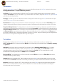
3. Next, you would need to enter all relevant information on the Sensor Info and Test Setup tabs (VCal™ will return an error message
if you attempt to initialize a test without providing all required information on each tab). For a description of each required field you
may review the information on pages 26 - 27.
4. When you have filled in all required fields on the Sensor and Test Setup tabs; then choose either “Linearity” OR “Hysteresis” on the
Test Setup Tab, and click on the Initialize Test button. This will fill in the Test Grid with the proper load points for your calibration.
The following is an example of a window similar to what you should see on your screen:
5. Next, you would need to fixture your sensor (see pages 49-50 for fixturing examples), and then tare your load cell by pressing the Tare button
(this puts all offsets in place and zeroes your display). You are now ready to begin taking readings. Click in the first Output box in the test grid,
next to zero, and press Enter to take your first zero reading. Next, load the cell to the first load point (50 lbs in this example), click in the output
box next to 50 and press Enter and VCal™ will take the reading. Repeat this process for each load point in the Test Grid.
6. Once you have taken the last reading, the “Linearize” button (on Test tab) will begin flashing; at this point you have the choice of whether
or not you wish to Linearize the load cell. A Hysteresis correction is also possible, for this correction you must select the hysteresis
option on the Test Setup tab before beginning a test. The correction works by applying a linearization factor on the loading and
unloading of the cell. Hysteresis corrections are only applied when doing a calibration on the Sensor Calibration window. Just click the
Linearize button to apply the corrections. The first linearization coefficients are applied on the loading of the sensor up to full scale.
After that, the hysteresis coefficients are applied during the unloading of the sensor.
7. Under Scaling, enter the rated output of the load cell: For example if a 5000 lb cell is rated at 2.000 mV/V (from cert or test), you should
enter 2.000 mV/V even if you are only loading to a calibration load of 500 lbs. Enter your Default Decimal Points to display. Over Load
Threshold determines at what level VCal™ will issue a red, flashing Sensor Overload Warning. Over Range Threshold determines at what
level VCal™ will issue a yellow, flashing Outside Calibration Range Warning.
©Futek Advanced Sensor Technology 2005
40
Futek Advanced Sensor Technology – Futek VCal™Documentation
Rev. 1.8.0
07/26/05
8. Make sure the system is at zero load, press tare and then load to your calibration load. Click in the Output Box, press Enter and VCal™ will
take the current reading. If you wish to recalibrate, just unload your sensor, press TARE and reload to your desired calibration load. The reading
taken will still be in mV/V even though the display is showing a scaled output. Press “Scale To Unit” to calibrate. You will have to re-save the
data iin order to store new calibration factors if you have saved the test previously. You won’t have to do a multi-point loading again unless you
wish to. During the scaling procedures the linearization factors are being applied. If entering calibration data in Manual Mode from a precalibrated load cell, the scaling factor will be estimated automatically.
9. Unless you are using VCal™ in Manual Mode, the test temperature will be automatically recorded.
10. You will now want to save the test, and you have calibrated your VCal™ Reference Sensor.
11. Manual Mode is used when entering calibration information that was done by a third party and calibration equipment is not available for a
self calibration.
©Futek Advanced Sensor Technology 2005
41
Futek Advanced Sensor Technology – Futek VCal™Documentation
Rev. 1.8.0
07/26/05
Introduction To Performing A VCal™ Calibration / Verification
You are nearly ready to do some calibrating, however; before we step through some Calibration Examples, there are several items which require
some additional explanation. Testing Modes, Testing Options, Testing Parameters and Test Conditions are all items which really need
to be explained a little before we proceed. All of these can be found under the Setup tab. We will also talk some more about the three types of
testing you can do in the Calibration / Verification interface; the Main Test, the Time Test, and the Signature Test.
Testing Modes
Under the Testing Modes section of the Setup tab you have a choice of whether you wish to use Normal, Extrapolation, or Actual Modes,
when you perform your test. Let’s define what these calibration modes actually are.
Normal Mode Calibration: This is your default calibration mode. In this type of calibration you load your sensor to as close as possible to the
load points indicated in the Load column of the Test Grid window, pressing Enter at each load point. Each time you press Enter, VCal™ takes an
output reading and calculates the non-linearity (and hysteresis if selected), based on the deviation from the nominal or ideal value.
Extrapolation Mode Calibration: In this calibration mode you load your sensor to a point somewhat close to the indicated load point
(max+/-10% of load), and press Enter, and VCal™ takes a reading at the point you actually hit Enter at and extrapolates the output at the the
load value indicated in the Test Grid. It calculates the non-linearity (and hysteresis if selected) based on the deviation from the nominal. For
Example; If you pressed Enter at 79.3 lbs load, and your output was 0.5335 mV/V, but the load indicated in the Test Grid is 80 lbs, then; 80.0
lbs X (0.5335/79.3) = 0.5402 mV/V (this would be VCal™’s output reading in Extrapolation Mode under the test conditons described.
Note: Extrapapolation Mode only works when you have a calibrated reference cell connected as well as your test cell, and all
channels must be designated correctly for the calculations to work correctly.
Actual Mode Calibration: In this mode you take readings at any pattern of points you desire, pressing Enter at each point, and VCal™ takes
a reading at that point, and changes the indicated loads in the Test Grid to reflect the points at which you pressed Enter. VCal™ then gives
an output reading at that point, and calculates the non-linearity based on the deviation from the new nominal value. For Example; If the load
indicated on VCal™’s Test Grid is 80 lbs and you press Enter when there is only 79.3 lbs of load applied, then VCal™ will change the value
indicated in the Test Grid to 79.3 lbs and will display the output value that corresponds to 79.3 lbs of load.
Note: Because hysteresis requires exactly matching ascending as well as descending load points, it is not available in this mode of
calibration.
Testing Options
Manual Entry: Manual Entry allows you to enter data from a certificate or a different data acquisition system, through the keyboard, directly into
the Test Grid. The use of Manual Entry actually prevents the program from obtaining data from the VCal™ module. With Manual Entry you
can enter the Load and Output values from your test, and VCal™ will caluclate the non-linearity (and hysteresis if you selected it) as soon as
you press Enter in the final zero output box in the Test Grid.
Scaled testing: Scaled Testing is designed to be used when data is being entered from an outside source which has already been scaled to a
known unit, such as a pre-calibrated Sensor-Display system (Futek D500 series). If you are using a sensor that is giving you a raw output in Volts
or mV/V you cannot use Scaled Testing, because your scaling factor is unknown at this time. Using Scaled Testing changes the way in which errors
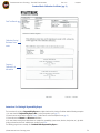
are calculated. Below are a couple of examples which illustrate the procedures used to calculate errors in both Scaled and Non-Scaled Testing:
Non-Scaled Example: (Output in mV/V)
0
0.0000
20
0.3995
LOAD
40
0.8000
OUTPUT
60
1.2000
80
.6000
100
2.0000
In this case the error is a percentage of full-scale, for example
the error at 20 lbs is ((0.4000 - 0.3995) / 2.0000) * 100
= 0.025% of full-scale. Note that 0.4000 is the ideal output
at a load of 20 lbs.
©Futek Advanced Sensor Technology 2005
Scaled Testing: (known output in lbs, kg, etc.)
0
0.0
20
19.8
LOAD
40
39.9
OUTPUT
60
60.0
80
79.7
100
101.3
In this case the error is a percentage of load, for example; the error
at 20 lbs is ((20 - 19.8) / 20) * 100 = 1% of the Load.
42
Futek Advanced Sensor Technology – Futek VCal™Documentation
Rev. 1.8.0
07/26/05
Test Parameters
Under the Test Parameters section of the Setup tab there are are options for defining the number of Load Points (required to perform a test),
Averaging, Decimal Points, and Target Load Warning Tolerances.
Load Points: This field is required to perform a calibration or test. This is where you define how many points in the load range you will take
readings at. For example; if your cell is rated at 500 lbs, your calibration load is also at 500 lbs, and you set Load Points to 5, your Load Points
will be 100, 200, 300, 400, and 500 lbs.
Averaging: The number you enter here determines the number of readings VCal™ will take when you press Enter, and then return an output
value that is an Average of all the output readings taken.
Decimal Points: This setting is where you determine the resolution of the data points. This box is only used with the Manual Entry mode of
calibration. Under normal calibration or testing circumstances the number of decimal points will be determined by the resolution of the display.
Target Load Warning Tolerance: This setting allows you to set a tolerance level with regards to your load points, so that VCal™ will issue a
warning that you are within the tolerance level you have set of your load point. For example; if your first load point is 50 lbs, and you have your
Target Load Warning Tolerance set to 1, then when you increase the load applied to 49 lbs, VCal™ ‘s display screen background will change
from Black to Yellow to let you know that you are within the 1 lb tolerance level you have set. The number you enter in the Tolerance box is
an increment of whatever units you are measuring your load with. If you enter a 2 in the box, and you are measuring your load in kilograms; then
VCal™ will issue a warning when the load applied is within 2 kgs of the load point.
Test Conditions
The final section of the Setup tab is the Test Conditions section. Here is where you decide whether to perform your calibration using
VCal™’s Auto Read function, or maybe to read from an RS232 device, and also where you decide whether to test for Linearity or Linearity
and Hysteresis.
Auto Read: By selecting this option you are telling VCal™ that you wish to utilize the Automatic Reading Taking function. This feature
works like a normal calibration except that you do not need to press Enter as you reach each Load point. With Auto Read selected you
simply start loading your sensor, and as you reach each load point indicated in the Test Grid, VCal™ will automatically take a reading
and display the corresponding outptut value in the Output column of the Test Grid.
Read from RS232: This setting allows you to read from an externally connected RS232 device (such as the Futek D500 series displays),
and display the data on your VCal™ display.
Linearity: With this type of calibration, VCal™ takes a reading every time you press Enter on the ascending loading of your sensor, returns
an output value to the Test Grid, and calculates the non-linearity error based on your output’s deviation from the ideal value at that load point.
Hysteresis: With this type of calibration, VCal™ takes a reading every time you press Enter on both the ascending and descending loading
of your sensor, returns output values for each point, and then calculates the error based on the differences between the ascending and
descending output values at each load point.
©Futek Advanced Sensor Technology 2005
43
Futek Advanced Sensor Technology – Futek VCal™Documentation
Rev. 1.8.0
07/26/05
Now we need to talk a little about the three types of testing which are available to you in the Calibration interface. I told you a little earlier that
we would give some more details about the Main Test, the Time Test, and the Signature Test. The Main Test is the default type of test, and
iwhat type of test you will perform if you do not select either Time or Signature Test on the pull-down menu available from the hand signing icon in
the row of command buttons along the top of the interface window (see page 30 for location).
Main Test
The Main Test is the default, or standard calibration type. It consists of you entering all the required information asked for on the Information
Tabs sections of the interface (the Info, Initial, Setup, and Test tabs), followed by you pressing Begin Test on the Setup tab,, and then taking
a first zero reading with your sensor unfixtured on the Test tab. You would then fixture your sensor, click into the Output box to the right of the
first Load point (0) in the Test Grid, and press Enter. After this you would proceed through the load points indicated on the Load column of the
Test Grid, after clicking into each of the output boxes in a progressive fashion (0 through full scale, then final zero still fixtured) in the Test Grid.
After this you would take a final zero reading with your sensor unfixtured on the Test tab, and possibly view your Uncertainty and Zero Return
values on the Test tab. You would then have the options of saving, graphing, or printing certificates and reports stating the results of your
calibrations and tests.
Time Test
Selecting the Time Test option in the pull-down menu brings up the following screen, where you can perform VCal™’s Time Test calibration.
Here you are able to run a timed test with readings taken at pre-defined intervals, watch the graphic display of the outputs in real time, and
also save the results of these timed tests to a file of your choosing. The screen below and the descriptive text that accompany it will give you an
overview of the Time Test interface; more detailed instructions for using this interface will be given in the Instructions For Performing
A Calibration Verification section of this Manual. (pg. 47)
Vert Lo - This setting determines the lower output limit which will
be displayed on the Time Test Grid. This output is displayed in
the same units you have chosen for output.
Vert Hi - This setting determines the upper output limit which will
be displayed on the Time Test Grid. This output is displayed in the
same units you have chosen for output.
Time Lo - This setting determines the start time for your test run.
Please note that negative start times aren’t valid, you must start
your test at 0 seconds start time or higher.
Time Hi - This setting determines the end time for your test, or if
your start time is 0, the length of your test. Please note that all
end, as well as start times are in seconds. You may also choose
to make your test continuous (no end time) by selecting the
Continuous checkbox.
Initialize - This button initializes the test grid with traces for the
Channels you have selected in the Channels section.
Interval - This option allows you to set at what interval VCal™
will take readings. These can be set at any increment of 0.1s. For
example; if you have Time Hi set to 10s, and your Interval set to
0.1s, then VCal™ will take 100 readings during the test.
Save To File - This option allows you to save the data from your
test to a spreadsheet application file.
File - Click this button and point the window at the location of the file where you wish to save your data.
Channels - Here you select which channels you wish to have displayed on the Grid during the test.
Start / Pause / Stop - These buttons give you contol over your test by allowing you to Start, Pause, or Stop your test at any time.
©Futek Advanced Sensor Technology 2005
44
Futek Advanced Sensor Technology – Futek VCal™Documentation
Rev. 1.8.0
07/26/05
Signature Test
In this type of calibration you are given the chance to take advantage of Futek VCal™’s tools for Signature Checking. This tool allows you to
monitor and control the performance of your sensors. Here you can define a Primary ‘signature’ for a sensor; VCal™ will create a profile for
your sensor, recording such characteristics as Output, Non-Linearity, and Hysteresis. Then, you can perform Subsequent tests and match the
characteristics of your Subsequent Test against the Primary Signature Test characteristics. This allows you to track the performance of your
sensor, and allows you to identify non-conforming trends in their earliest stages. This aids in the establishment of performance traceability, and in
the definition of calibration intervals, and gives added assurance in the reliability of your calibration measurement results. If you load a saved test
on the sensor you wish to perform Signature Checking on, and then select Signature Test under the Signing Hand icon pulldown menu, you
will first see the following screen . . .
Here you can see a list of the Signature Test Profile Tests you have
performed on this specific cell. Select all of the tests you wish to compare the
results of.
Under the Comparison section of the pane you can select which output
characteristics of the tests you wish to compare.
Once you have selected which tests you wish to compare, and you have
selected which characteristics of these tests to include in your comparison,
you can press the Generate Data button to bring up the next screen . . .
Here you can see that I have selected all three saved tests, one Primary (P),
and two Subsequent (S), and that I have chosen Output as my
characteristic to compare.
Then when I pressed Generate Data it brought up the this comparison Grid.
In this Grid VCal™ lists the load points, (which must be same in all tests you
wish to compare), the outputs in all three tests and the percentage of error
between the first and second tests, and the first and the third tests. Had I
chosen Non-Linearity instead of Output in the Comparison area,
the Comparison Grid would have shown the Load points from the three
tests, the the Non-Linearity errors from the three tests, and the percentage
of error between the readings of the tests. Had I chosen Hysteresis the Grid
would have displayed the appropriate hysteresis data.
There is also a button marked Export Data, clicking this will bring up
this Save Text File in Desired Path box; here you can specify where
to save a text version of your test. Just give your test file a name, and
specify where on your hard drive or Removable media to save the file
to, and it may be referenced later for analysis, or performance monitoring
activities.
©Futek Advanced Sensor Technology 2005
45
Futek Advanced Sensor Technology – Futek VCal™Documentation
Rev. 1.8.0
07/26/05
Instructions For Performing A Calibration Verification
A test cell calibration describes the procedure determining the sensitivity of an unknown sensor, or a repetition of previous tests to acquire
comparable data. The sensor calibration interface allows you to test various sensors under a pre-determined load. The load would usually be
supplied by a pre-calibrated reference sensor or a dead weight load or pressure system. When the interface is loaded you will choose initially
which channel the reference sensor is connected to and which channel the test sensor is connected to. It makes no difference which cell is
connected to which channel, although under normal circumstances channel 1 would be used for the reference sensor.
Now that you have gotten familiar with the layout of the Calibration interface, and we have discussed configuring your test (setting Test Modes,
and Options, Conditions and Parameters), and we have discussed the three different types of tests (Main, Time, and Signature), let’s walk
through a couple of examples and take a look at some pictures that will illustrate the calibration procedures described here.
Example Calibration Verification (Main Test): (Please refer to the screen shot below as a visual aid for performing the following steps:)
1. The first step in performing a Calibration Verification is to fill in all the information we have just talked about; starting with the Info tab, to
the Initial tab, and on through the Setup tab. Once you have filled in all required information on these three tabs you can press the Begin Test
Button, and the Test Grid will be filled in based on the information you have provided on these Information Tabs.
2. Once the Test Grid appears with the Load Points you chose filled in, you will want to connect the reference and test sensors to the
appropriate channels (if they are not connected already), and the temperature probe to the Power Face Plate of your VCal™.
3. The next step would be to take a First Zero (unfixtured) reading by going to the Test tab, making sure the cell is under no load,
pressing the Gross button on the Test Grid window, clicking into the First Zero text box, and either pressing Enter, or clicking the
Un-fixtured button next to the First Zero text box.
4. Next you would fixture your sensors, Tare both channel displays, click into the first output grid box and press Enter to take a
first fixtured zero reading.
5. Next you would click into the second output grid box, load the cells (with either dead weight or pressure system) until the reference
cell display reflects the first load point ( 500 lb in our example), and then press Enter.
6. Repeat Step 5 for each of the remaining load points.
7. Take a final fixtured zero with no load applied, by clicking into the last output grid box and pressing Enter.
8. Take a final unfixtured zero with no load applied, by clicking into the Final Zero Box, and pressing Enter.
Step 3
Step 8
Step 4
Step 5
Step7
©Futek Advanced Sensor Technology 2005
46
Futek Advanced Sensor Technology – Futek VCal™Documentation
Rev. 1.8.0
07/26/05
9. The only things left to do is to save your test by clicking the Save button
, If this is the first time you have saved a test under this serial
number then VCal™ will save the test without any further prompting. If however, this serial number has been saved before, then VCal™ will ask
whether you wish to Write Over An Existing Record or Create a New Record....... simply choose the option which works best for your application.
Example Calibration Verification (Time Test):
1. The first step in performing a Time Test is to connect your Reference and Test sensors to the appropriate channels (you may connect either
sensor to either channel, although connecting your Reference sensor to Channel 1 is the common connection method).
2. Next you would need to open the Calibration Verification interface if it is not already. Once you have opened the Calibration interface, you
will need to select Time Test from the pull down menu of the ‘Signing Hand’ icon. Once you have selected the Time Test option, you will see the
Time Test interface . . .
3. Next you need to set your Output limits (Vert Hi & Lo),
these are an increment of whatever Units your output is being
measured in.
4. Next you need to set the Start and End Times for your test.
Please note that the Start time cannot be less than zero, and
also that all times are measured in seconds. You can also choose
Continuous instead of setting Start .
5. Next you need to set the Interval (frequency of readings)
Please note that the interval can be set in increments of onetenth of a second, or 0.1seconds (You can also set your test to
run continuously by selecting the Continuous box).
6. Next you need to select all channels that you wish to run the
Time Test on.
7. Next you need to let VCal™ know if you wish to save the
results of your Time Test to a file by selecting or unselecting
the checkbox next to Save To File. If you choose to Save, you
should also click the File button, and point the resulting window
to the location of the Excel file where you wish to save your
results.
8. Finally, you will need to click the Initialize button to bring up the Time Test Grid, and then press Start to begin the test. You may temporarily
halt your test at any time by pressing Pause, or can cancel the test at any time by pressing Stop.
©Futek Advanced Sensor Technology 2005
47
Futek Advanced Sensor Technology – Futek VCal™Documentation
Rev. 1.8.0
07/26/05
Example Calibration Verification (Signature Test):
1. The first step in performing a Signature Test Calibration is to fill in all the required information on the Information Tabs (Info, Initial,
and Setup), be sure to check the checkbox next to Signature Test (at the bottom of the Info tab), and also to check either Primary or
Subsequent, whichever applies to your particular test. Once you have filled in all the appropriate information to configure your test, you can
press the Begin Test button on the Setup tab. Doing this will bring up the Test Grid, filled in per your configuration settings.
2. If you are performing this test right now, you would connect your sensors and proceed through the Instructions for Performing a Main Test
first, (see pgs. 46 - 47), and when you have completed and saved your test, continue with Step 3.
3. If you are comparing the results of previously performed calibrations which you have loaded from the database, you would then click on the
down-arrow icon just to the right of the ‘Signing Hand’ icon. This will bring up the pull-down menu where you can select the Signature Test
option. Clicking this option will bring up the Signature screen . . .
4. Here you can select which saved tests you wish to compare the results of. Select all that are appropriate to your needs. You can also select
which output characteristic you wish to compare the results of , here you can only compare one characteristic at a time. For this example I am
going to pick all three tests, and I will select Output as my characteristic to compare. Next you would press Generate Data, and that would bring
up this screen . . .
5. You have successfully completed your Signature Test. If you wish to save the comparison results to a file you may press the Export Data
button, and follow the directions there to save your results.
©Futek Advanced Sensor Technology 2005
48
Futek Advanced Sensor Technology – Futek VCal™Documentation
Rev. 1.8.0
07/26/05
Application Examples
The following are some examples of different types of calibrations being performed; and also some examples of how the VCal™ Reference
Sensor can be fixtured for these different types of calibrations. Of course your applications may be different than what is shown here. These
pictures are included for general guidance purposes only. This first picture shows the Futek VCal™ Reference Sensor hooked up in a hydraulic
Tension/Compression Calibrator machine, fixtured for a Force Calibration / Verification in Compression . . .
The following picture shows the Futek VCal™ System connected, and the Futek VCal™ Reference Sensor fixtured for Force Calibration /Verification
iin Tension . . .
The following picture shows the Futek VCal™ System connected, and the Futek T5410 (TDF 600) Reference Sensor connected for a Torque
Calibration / Verification of the Futek model T6005 (TAT 500) Torque Wrench . . .
©Futek Advanced Sensor Technology 2005
49
Futek Advanced Sensor Technology – Futek VCal™Documentation
Rev. 1.8.0
07/26/05
Application Examples - Continued
The following picture shows the Futek VCal™ Module connected, and the Futek VCal™ Reference Sensor fixtured for Pressure Calibration /
Verification, using a hydraulic pressure testing system . . .
The following picture shows two Futek VCal™ systems hooked up in a Multi-System manner with two Futek VCal™ Reference Sensors, using
the VCal™ Loading Tower in a Compression direction . .
©Futek Advanced Sensor Technology 2005
50
Futek Advanced Sensor Technology – Futek VCal™Documentation
Rev. 1.8.0
07/26/05
Instructions For Printing A Calibration Verification Certificate
Now that we have walked through the layout of the Calibration interface, we have talked about the methods of configuring your test to obtain
the types of results you desire. We have also talked about the three different types of calibrations you can perform (Main, Time, and Signature),
we have now walked through some examples of each type, and we have looked at some pictures of some different ways to fixture your
sensor for the different calibration directions. Now we need to talk about printing out reports and certificates which will state your results.
Print - Clicking this icon brings up the Print Options interface. Here you can search for and select which tests to print, set print options
before printing, decide whether you wish to print a simple report or a full certificate, decide exactly which fields you wish to include
or exclude in your print out or certificate, and decide exactly how you want the included fields named. This allows you to fully modify and
customize your print out or certificate to fit your individual application.
1. Under Print Options the first thing to decide is whether to print a
Certificate or a Repeatability Report. For our purposes we will list the
steps for printing a Certificate first, so we will leave the Repeatability Report
Box unselected for now.
Print Options Interface
2. Next, by simply selecting or unselecting the appropriate checkboxes, you can
decide whether to Preview the Certificate before printing, whether to include an
additional page which will show Company Information, whether to print your
Certificate with borders, and whether to include your Company Logo or not.
Please select or unselect the options as you see fit.
3. Also under Print Options; pressing Report Captions shows the following
screen where you have the option of changing how any of the fields are
labeled on your Certificate. The first column on this screen shows the maximum
allowed length for the name of this field; the second column shows VCal™’s
current name for the field; the third column shows the name which will be
displayed on the Report or Certificate. To edit the name which is displayed on
your Certificate or Report, simply click on it in the Report Captions Screen,
then type the name you wish to appear in the Display Caption text box on the
right half of the Report Captions Screen. In the example below; VCal™’s name
for the field is Sensor ID, the Display Caption name is Serial No, and I have
changed the Display Caption name to Sensor Number.
Report Captions Screen
COL 1 COL 2 COL 3
4. Under Print Options you are also given the chance to include your company logo on your Report or Certificate. To use this function simply
click on the Show Logo button, and then point the Save window at the location of your Company Logo file. (At this time VCal™ only supports
Logo files in the bitmap format).
©Futek Advanced Sensor Technology 2005
51
Futek Advanced Sensor Technology – Futek VCal™Documentation
Rev. 1.8.0
07/26/05
5. Under the Search section of the Print Options interface, you can bring up a previously saved Certificate by entering a known Certificate Number,
or you can search for a particular test to print by entering the sensor Serial Number, pressing Enter, and then selecting the specific test you wish
to print by double clicking on it, and then pressing Print. Please note that to print a Certificate, you must select one, and only one test at a time,
6. This will bring up the “Print Settings” screen where you can choose exactly which sections are or are not included in your Certificate. Under
Template with Standard selected; Test Counter, Calibrated With, Best Fit Equations, Extended Test Results, Max Non-Linearity, and Max Hysteresis
are all sections that you can choose to include or not include. Under Template with Custom selected; all of the above-mentioned sections, and also
Customer Address and Last Page Statements (Calibration Technician, etc.) can be selected for including or excluding from your Certificate.
Print Options Interface
Print Settings Screen
7. Once you have decided on, and selected all of the Sections you wish to include on your Report or Certificate, then pressing Print will either
allow you to preview the certificate (if you selected the Show Settings Before Printing checkbox on the Print Options interface), or print the Report
On the following pages is an example of the Standard Mode Calibration Certificate with all Sections selected…
©Futek Advanced Sensor Technology 2005
52
Futek Advanced Sensor Technology – Futek VCal™Documentation
Rev. 1.8.0
07/26/05
Standard Mode Calibration Certificate (pg. 1)
Customer Information
Sensor Information
Reference Sensor
Information
Test Results Information
Best Fit Equation
Information
©Futek Advanced Sensor Technology 2005
53
Futek Advanced Sensor Technology – Futek VCal™Documentation
Rev. 1.8.0
07/26/05
Standard Mode Calibration Certificate (pg. 2)
Final Test Results
Calibration Closing/
Disclaimer Statements
Company /
Calibration Lab
Information
Instructions For Printing A Repeatability Report
The instructions for printing a Repeatability Report are identical to those for printing a Certificate with the following exceptions:
1. You must check the Repeatability Report Box; (on the Print options screen pg. 51)
2. Enter the sensor serial number and press’ Enter ‘; (Under Search on the Print Options screen pg. 51)
3. Choose the correct Channel and Direction information;
4. You must choose exactly three identical tests to compare for repeatability (same sensor, direction, load points, etc.), by double
clicking on them from the list of available tests, and then press Print.
The following pages show an example of a Standard Mode Repeatability Report....
©Futek Advanced Sensor Technology 2005
54
Futek Advanced Sensor Technology – Futek VCal™Documentation
Rev. 1.8.0
07/26/05
Standard Mode Repeatability Report (pg. 1)
Customer Information
Sensor Information
Reference Sensor
Information
Test Conditions
Information
Test Results
Information
Best Fit Equation
Information
©Futek Advanced Sensor Technology 2005
55
Futek Advanced Sensor Technology – Futek VCal™Documentation
Rev. 1.8.0
07/26/05
Standard Mode Repeatability Report (pg. 2)
Calibration / Closing
Disclaimer Statements
Company / Calibration
Information
©Futek Advanced Sensor Technology 2005
56
Futek Advanced Sensor Technology – Futek VCal™Documentation
Rev. 1.8.0
07/26/05
V. Troubleshooting and Technical Support
Problems Powering on Your VCal™ Unit:
• Check that the red LED is lit on the ON/OFF switch faceplate of your VCal™. If not then . . .
• Check that the wall AC outlet is operating correctly
• Check that all cable connections are secure
• Check that the fuse in your VCal™ unit has not been blown
Warning! – If you must open your VCal™ unit to change or check the fuse, we ask that you obtain Futek factory authorization and
instruction first, and then remove only the Power side faceplate! And please observe all precautions appropriate for the handling of
electronic components. Failure to observe these precautions could result in the voiding of your warranty !
• If Futek VCal™is closed incorrectly or unexpectedly ( USB cable gets disconnected etc.), you will need to restart the VCal™program.
Installation or USB Related Problems:
• If VCal™ gives a message that it was unable to locate the driver files, please make sure you are not on the Internet, and use the Browse
function of the dialog window to point VCal™ to the folder labeled Drivers in the Removable Drive that VCal™ installed.
• Check that USB Devices are enabled in your PC’s BIOS setup
• Please shut the unit off and power on again
• Windows XP users - If you receive any incompatibility messages, please disregard. We are in the process of working this detail out.
General Safety and Use :
• Please observe all appropriate safety precautions for electronic devices.
• Please do not short circuit +E and –E.
• Please do not short circuit power and common.
• Please only run your Futek VCal™ from the installed ‘Removable Drive’ only. Failure to do so could cause VCal™ to become unstable.
• Please do not use in conditions of extreme heat or cold. (Operating Temperature = 0 to 60° C.)
• Please do not consume food or beverages near your VCal™unit.
• Please do not open your VCal™unit, unless you have to check or change the fuse, and then obtain Futek factory authorization and
instruction first, and then observe the above-mentioned warning.
• There is a slight delay when printing a report or certificate before the preview image comes up, this is normal and unavoidable due to the
Crystal viewing components
• Please note that because of the significant amount of resources required by the 3D graphing program, we recommend that it be used
on systems utilizing at least 128 MB of RAM and with a processor speed of at least 400 MHz.
To Contact Futek :
• Email us at [email protected]
• Or, call us directly at 800–23–FUTEK or at 949-465-0900
©Futek Advanced Sensor Technology 2005
57
Futek Advanced Sensor Technology – Futek VCal™Documentation
Rev. 1.8.0
07/26/05
VI. Futek VCal™Specification Page
Physical Specifications :
• Length – 123/8 in or (31.5 cm)
• Width – 6 in or (15.24 cm)
• Height – 15/8 in or (4.06 cm)
• Weight – 2.8 lbs. or (1.27 kg)
VCal™Data Acquisition Module Specifications :
• Resolution: ± 20 bits
• Input range: ± 4.5mV/V
• Analog input range: ±15 VDC, 4 – 20 mA
• Power Supply Output: 15 VDC @ 2A
• Default Shunt Cal Values: 60.4KΩ, 100KΩ, and 150KΩ (Other Shunt Values available per customer request)
• Measuring rate: 4.7 to 600 Hz
• Filter frequency: 0.25 to 40 Hz
• Storage Temperature: 0 to 60° C (32 to 140° F)
• Temperature Probe Range: -55 to 125° C (-67 to 257° F)
• Sensor Connection: 4 wire
• Fuse: 250V @
©Futek Advanced Sensor Technology 2005
58
Futek Advanced Sensor Technology – Futek VCal™Documentation
Rev. 1.8.0
07/26/05
VII. Futek VCal™Glossary of Terminology
A2LA The American Association for Laboratory Accreditation. (http://www. a2la2.net)
Accuracy Stated as a limit tolerance which defines the average deviation between the actual output versus theoretical output. In practical
transducer applications, the potential errors of nonlinearity, hysteresis, nonrepeatability and temperature effects do not normally occur
simultaneously, nor are they necessarily additive. Therefore, accuracy is calculated based upon the RMS value of potential errors, assuming a
temperature band of ± 10° F, full rated load applied, and proper set up and calibration. Potential errors of the readout, crosstalk, or creep
effects are not included.
ANSI The American National Standards Institute. (http://www.ansi.org)
ASTM The American Society for Testing and Materials. (http://www.astm.org)
Audit Trail The chronological set of records that provides evidence of system activity. These records can be used to reconstruct, review and
examine transactions from inception to output of final results. The records can also be used to track the calibration history of a reference sensor
back to it’s original calibration (generally with NIST calibrated dead weights).
Average to Best Fit Output The average of the standard deviations between the individual measured outputs and the Best-Fit Outputs for each
load point.
Axial Load A load applied along a line concentric with the Primary Axis.
Best Fit Equation The equation of a straight line, calculated from a set of measurement results, which attempts to minimize the differences
(usually called residuals) between the line and the measurement results. There is more than one statistical method used, each of which may place
the straight line in a slightly different position with respect to the measurement data.
Calibration Certificate For the purposes of this Glossary; A document which lists all of the information relevant to a Calibration (Customer info,
Sensor info, Test Conditions, Test Results, etc.), and certifies that the information is accurate within a certain limit of uncertainty.
Calibration Curve A record of the comparison of the transducer outputs versus standard test loads.
Calibration Interval A period of time or amount of use between calibrations determined to be adequate to ensure equipment remains reliable,
where reliable is defined as within sufficient tolerance (or uncertainty) for the tests being done.
Calibration Load For the purposes of this Glossary; The maximum load which is to be applied during a particular Calibration.
Calibration The comparison of transducer outputs against standard test loads.
. Compensated Temperature The range of temperature over which the transducer is compensated to maintain Rated Output and Zero Balance
within specified limits.
.Correction Factor Numerical factor by which the uncorrected result of a measurement is multiplied to compensate for systematic error.
Creep The change in transducer output occurring with time, while under load, and with all environmental conditions and other variables remaining
constant. Usually measured with Rated Load applied and expressed as a percent of Rated Output over a specific period of time.
Crosstalk With one component loaded to capacity, and the other unloaded, the output of the unloaded component will not exceed the percentage
specified of its full-scale capacity. .
Deflection The change in length along the Primary Axis of the load cell between no-load and Rated Load conditions.
Drift A random change in Output under constant Load conditions.
©Futek Advanced Sensor Technology 2005
59
Futek Advanced Sensor Technology – Futek VCal™Documentation
Rev. 1.8.0
07/26/05
.
Error The algebraic difference between the indicated and true value of the load being measured. Error is numerically equal to correction but
opposite in sign.
Excitation The voltage or current applied to the input terminals of the transducer.
Hysteresis The maximum difference between the transducer output readings for the same applied load;
one reading obtained by increasing the load from zero and the other by decreasing the load from Rated Output.
Usually measured at half Rated Output and expressed as a percent of Rated Output. Measurements should be
taken as rapidly as possible to minimize Creep.
IEEE Standard 1451.4 (Institute of Electronic and Electrical Engineers) Standard for Plug and Play for Sensors and Signal Conditioning
(http://www.ieee.org)
.ISO International Organization for Standardization. (http://www.iso.ch/iso/en/ISOOnline.frontpage)
Linearity The closeness of a calibration curve to a specified straight line. Linearity is expressed as the maximum deviation of any calibration point
on a specified straight line during any one-calibration cycle.
.
Load Cell A force transducer typically employing strain gages to measure elastic deformation, which produces an output signal that is proportional
to the applied load or force.
Load The weight, torque, pressure or force applied to the transducer.
.
Natural Frequency The frequency of free oscillation under no-load conditions.
.
NIST National Institute of Standards and Technology (http://www.nist.gov)
Non-linearity The maximum deviation of the Calibration Curve from a straight line drawn between the No-load and Rated Load outputs, expressed
as a percentage of the Rated Output and measured on increasing load only.
Non-repeatability The maximum difference between transducer output readings for repeated loadings under
identical loading and environmental conditions. .
Operating Temperature The extremes of temperature within which the transducer will operate without
permanent adverse change to any of its performance characteristics.
.
Primary Axis The axis along which the transducer is designed to be loaded; normally its geometric centerline.
.
Rated Load (Rated Capacity) The maximum Axial Load that the transducer is designed to measure within its specifications.
.
Rated Output The signal (voltage) produced by the transducer. Where the output is directly proportional to excitation, the signal is expressed in
terms of (mV/V) of excitation.
.
Reference Sensor Sensor, generally having a known, output versus load quality, at a given location or in a given organization, from which
measurements made there are derived. The reference sensor itself must be periodically claibrated.
Repeatability (of results of measurement) Closeness of the agreement between the results of successive measurements of the force carried out
under the same conditions of measurement. Conditions include same procedure, observer, instrument, conditions, and location; and carried
out over a short period of time.
Repeatability Report For the purposes of this Glossary; a document which reports the results of comparing three separate, but identical,
test for closeness of result agreement.
©Futek Advanced Sensor Technology 2005
60
Futek Advanced Sensor Technology – Futek VCal™Documentation
Rev. 1.8.0
07/26/05
Reproducibility (of results of measurements ) Closeness of the agreement between the results of measurements of the force carried out under changed
conditions of measurement. Includes changing some of those conditions that are held constant for ‘repeatability’, and may refer to measurements carried out
over a long period of time.
Resolution The smallest change in mechanical input which produces a detectable change in the output signal.
.
Safe Overload The maximum load in percent of Rated Capacity that can be applied without producing a permanent shift in performance characteristics beyond
those specified.
Scale Factor The full-scale output minus any offsets, divided by the full-scale load applied.
.
Sensor Element of a measuring instrument or measuring chain that is directly or indirectly affected by the measurand.
Shunt Calibration Electrical simulation of transducer output by insertion of known shunt resistors between appropriate points within the circuitry.
Signature Test A type of calibration procedure which involves performing a Primary test under repeatable conditions to establish a sensor’s “signature” (output,
non-linearity, and zero characteristics), so that Subsequent tests may be performed to be compared against this Primary
Signature for performance monitoring and control.
.
Span Modulus of the difference between the two limits of a nominal range. (Maximum - Minimum = Span)
Standard Deviation A mathematical quantity used to characterize the dispersion of results.
Strain Gage A measuring element for converting force, pressure, torque etc., into an electrical signal.
Tare The weight of the container in which goods are packaged, and a deduction from the gross weight to compensate for this.
Temperature Shift Span The change in Output due to a change in transducer temperature.
Expressed as a percentage of load per degree Fahrenheit (Celsius) change in temperature. .
Temperature Shift Zero The change in Zero Balance due to a change in transducer temperature.
Expressed as the change in Zero Balance in percent of Rated Output per degrees Fahrenheit (Celsius)
(change in temperature).
Time Test A type of test procedure which involves setting a start and end time for the test, setting limits on viewable outputs (Hi and Lo limits), and setting the
Interval (how often VCal™ is to take and save readings during the duration of the test).
.
Uncertainty of Measurement A parameter, associated with the result of a measurement that characterizes the dispersion of values that could reasonably be
attributed to the measurand.
Validation Confirmation by examination and provision of objective evidence that the particular requirements for a specific intended use or purpose are fulfilled
(ISO 8402).
Verification Confirmation by examination and provision of objective evidence that specified requirements have been fulfilled (ISO 8402).
Wheatstone Bridge A network of four resistances, an emf source, and a meter connected such that when the four resistances are matched, the meter will show a
zero deflection or “null” reading.
Zero Balance The output signal of the transducer with rated Excitation and with no-load applied usually expressed in percent of Rated Output.
Zero Offset The difference expressed in degrees between true zero and an indication given by a measuring instrument.
Zero Return The difference in Zero Balance measured immediately before Rated Load application of specified duration, and measured after removal of the load,
and when the output has stabilized.
.
Zero Stability The degree to which the transducer maintains its Zero Balance with all environmental conditions and other variables remaining constant.
©Futek Advanced Sensor Technology 2005
61
Futek Advanced Sensor Technology – Futek VCal™Documentation
©Futek Advanced Sensor Technology 2005
Rev. 1.8.0
07/26/05
62
Futek Advanced Sensor Technology – Futek VCal™Documentation
©Futek Advanced Sensor Technology 2005
Rev. 1.8.0
07/26/05
63
Futek Advanced Sensor Technology – Futek VCal™Documentation
©Futek Advanced Sensor Technology 2005
Rev. 1.8.0
07/26/05
64
Futek Advanced Sensor Technology – Futek VCal™Documentation
©Futek Advanced Sensor Technology 2005
Rev. 1.8.0
07/26/05
65