1
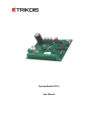
SECURITY MODULE SP131 User manual 1 CONTENTS SAFETY REQUIREMENTS .................................................................................................................................3 DESCRIPTION OF THE SECURITY MODULE SP131 ............................................................................................4 COMPATIBLE MODULES................................................................................................................................... 6 TECHNICAL PARAMETERS ................................................................................................................................. 7 PACKAGE CONTENT ........................................................................................................................................ 7 MODULE COMPONENTS .................................................................................................................................. 8 TERMINAL BLOCK DESCRIPTION ......................................................................................................................... 8 LIGHT INDICATION ......................................................................................................................................... 8 INSTILLATION .................................................................................................................................................9 INSTILLATION GUIDELINES ................................................................................................................................ 9 WIRING DIAGRAM ....................................................................................................................................... 10 SETTING UP OPERATING PARAMETERS OF THE MODULE ............................................................................. 12 CONNECTING TO A COMPUTER VIA USB ........................................................................................................... 12 CONNECTING TO A COMPUTER VIA GPRS ......................................................................................................... 13 SPCONFIG SOFTWARE ................................................................................................................................... 14 SETTING THE MAIN CHARACTERISTICS OF SECURITY MODULE ...................................................................... 14 USER CODE MANAGEMENT ................................................................................................................. 16 INPUTS........................................................................................................................................... 17 SMS TEXT ...................................................................................................................................... 18 PGM OUTPUTS ............................................................................................................................... 18 CMS REPORTING ............................................................................................................................. 19 USER REPORTING ............................................................................................................................. 20 EVENT SUMMARY ............................................................................................................................. 21 BUS MODULES ................................................................................................................................. 21 MCI BUS MODULES ......................................................................................................................... 21 EVENTS LOG .................................................................................................................................... 22 RESTORE TO DEFAULT PARAMETERS...................................................................................................... 22 FIRMWARE UPGRADE ........................................................................................................................ 22 SECURITY SYSTEM CONTROL ........................................................................................................................ 23 CONTROL BY SMS ....................................................................................................................................... 23 CONTROL BY THE KEYPAD PROTEGUS ............................................................................................................... 24 CONTROL BY THE KEYPADS OF PARADOX ........................................................................................................... 26 ANNEX 1. ZONE TYPES .................................................................................................................................. 28 ANNEX 2. PGM OUTPUT TYPES ..................................................................................................................... 29 ANNEX 3. WARRANTY AND LIABILITY RESTRICTIONS .................................................................................... 31 Safety requirements Please read this manual carefully before using the security module SP133. Security module should be installed and maintained by qualified personnel, having specific knowledge regarding the functioning of GSM devices and safety requirements. The device must be disconnected from external power supply source before starting device installation. Module should be mounted in places with restricted access and in safe distance from any sensitive electronic equipment. The device is not resistant to mechanical effects, dampness and hazardous chemical environment. Casings, transformers, batteries and programming devices must conform to LST EN60950 standard safety requirements. nd Security module is powered from 16-24V DC source or with 16-18V through a 2 class power transformer from a 50 Hz frequency alternating current power grid. For backup power batteries with 12 V/7 Ah or higher capacity must be used. Current consumption of the module depends on load of all connected external devices. An automatic bipolar overload cut-out must be installed in the electricity supply circuit to safeguard from a current overload in the power grid. Release contacts separation must be ≥ 3mm. Cut-out must be installed in a place well known to the personnel maintaining the module. The device is disconnected from the power source: From alternating current source – by switching off the automatic cut-out; From direct current source (e. g. battery) – by unplugging the clamps. 3 Description of the security module SP131 The module SP131 is an intruder and fire alarm control panel with an integrated GSM modem which can transmit event messages through GPRS connection or SMS messages to central monitoring station as well as SMS messages can be sent to user mobile phone. Messages are sent encoded in codes of Contact ID protocol and/or plain text. Features: Arming/disarming of the security system The module can be armed/disarmed by: Protegus SK130LED W/B, Paradox MG32LED, K636 and MG10LED keypads; OS Android smartphone or tablet with GSM modem app “Protegus“; Telephone call; Telephone SMS message; iButton switch; Code or other electrical switch. Setting of the operating parameters via USB All operating parameters of the SP module can be set with an OS Windows computer via USB cable by using program SPconfig. 5V power supply from USB is sufficient for module programming. Set parameters are stored in the memory of the module for storage period. Management of operating parameters and the module from central monitoring station It is possible to change the operating parameters, turn off zone control (bypass), change state of PGM output, ARM and DISARM or update firmware of the already installed module from central monitoring station. This feature is useful for organizing e.g. cash machine protection. Multifunctional data bus MCI The module has a single wire Multifunctional data bus MCI, which automatically recognizes and registers wired compatible devices (maximum 4): Additional transmitting module, which by VFH radio (T10C), Ethernet (E10C) or GSM/GPRS (G10) will transmit in parallel all event messages of the security system to central monitoring station. iButton key scanning device W131. Two-wire data bus YG (YEL/GRN) The module has data bus YG, which automatically recognizes and registers wired compatible devices (maximum 12): Keypads Protegus SK130LED W/B or Paradox MG32LED, K636, MG10LED. ZN inputs expander CZ8. 8 zones (expandable up to 32) The module has eight terminals ZN1–ZN8 for connecting to the sensor controlled external circuits. Zones number can be expanded up to 32 by using CZ8 expanders. Up to 12 various expansion modules can be connected to YEL/GRN data bus. For example: 4 keypads and 8 zone inputs expanders. An external circuit of any type (NC, NO or EOL=2,2 kΩ) can be connected to the terminals. Type of ZN circuit can be set as ON/OFF, Delay, Interior, Interior STAY, Instant, Instant STAY, 24 hours, Fire or Silent zone. Zone type defines how control panel should react to the event and restore of the zone. Fire zone Every ZNx input of the module can be set to Fire zone and four-wire fire detector can be wired to it. ZN8 terminal can be used for wiring of a two-wire fire detector. There is a Reset function for resetting twowire fire detectors by keypad command code or SMS. 4 4 PGM output The module has four programmable outputs PGM1–PGM4 for connecting of external circuits. Every output can be set to operate in any of 14 operating modes. Remote control of PGM outputs Output state can be controlled remotely by SMS or telephone call if the output mode is set to Remote Control by SMS or Remote Control by DIAL. This function helps remotely to control various devices (gates, healer, cooler, etc.) without changing security mode of the premises. Event messaging to any central monitoring station The module transmits messages to central monitoring station via GPRS or SMS communication channel. Information is sent in Contact ID protocol codes. For connection control with central monitoring station receiver PING signals are used. Several reporting IP addresses can be programmed. In case of a failed reporting to the main address, the messages will be reported to a backup address. If reporting fails to the main and backup addresses, the module will send SMS in Contact ID format to set number of central monitoring station SMS receiver. Event messaging to mobile phone Event messages can be sent as SMS messages to 5 mobile phones. SMS text of the event can be described in Lithuanian or Latin alphabet. It is possible to select sending SMS of specified events or all events. Event messaging to OS Android phone or tablet with GSM/3G modem Module can be set to send a special format SMS messages to OS Android device with installed app PROTEGUS. The app PROTEGUS will convert your OS Android device into user-friendly, informative and cost effective (depends on cost of SMS) console for security system control and management. PROTEGUS has easy to use widget for Arming/Disarming the system and checking the status of it. The widget enables to ARM/DISARM the system just in couple seconds and additional information will be readily available. Note. When choosing payment plans for Smart Phone and GSM module pay close attention to the cost of SMS messages. Module Calls Module can call to two phones if a specified event occurs, for example: robbery. Events for calling can be specified while setting parameters of the module. Calling function is useful then SMS sound is disabled and meaningful event occurs. Note: The alarm call has higher priority than security system control call or PGM output control call. When the module is calling to a user phone, all the incoming calls are rejected and commands controlled by call are not executed. It is highly recommended to configure the security system either to make alarm calling or be able to be controlled by call, but not the both at the same time. System status messages Module sends to programmed addresses the messages about robbery, fire, other hazard, system troubles such like power supply failure etc.; sends the Test messages in set time Test Time or in set period Test Period and also information who, when and how armed or disarmed the control panel. Bell Squawk function The function applied for sound indication of the security system arming/disarming. Door Chime function The module can inform with short buzzer signal about door opening and closing when system is in DISARM mode. BYPASS function The zones can be temporary bypassed for one security system arming period. It will allow to arm the system even if bypassed zone is violated. 5 Auto ARM function The function applied for protecting against accidental system disarming. If the security system is disarmed with a phone call and during the time for entry into the premises none of the secured zones are violated, the module will automatically rearm to previous ARM / STAY / SLEEP mode by itself. Event Log function Module registers and stores all the occurred events. Event log can be read by the program SPconfig. The occurred events are registered by their occurrence time, which is calculated by internal clock of the module. The main power supply from the AC or DC power source The module and the entire alarm system can be powered by standard 16-18V AC or 16-24V DC power supply. The latter feature is useful then premises are not connected to electricity network and the security system must be powered from an independent source of energy (e.g., solar power). Power supply voltage is monitored. If there is a problem with power supply it will be reported to central monitoring station and user (depends on settings of module). Compatible modules These modules can be wired to YG (YEL/GRN) or MCI bus. CZ8 W131 Product code Bus YG MCI Description Input expander up to 8 zones Interface with scanning device of iButton key codes Radio transmitter sending messages in VHF radio frequencies Ethernet communicator sending messages through internet networks T10R MCI E10C MCI GM10 MCI PROTEGUS SK130LED W/B YG Paradox K636 Paradox MG10LEDV and MG10LEDH Paradox MG32LED YG 16 zones touchscreen LED keypad with white or black glass 10 zones LED keypad YG 10 zones LED keypad 50-100 mA YG 32 zones LED keypad 50-150 mA GSM communicator sending messages over GPRS 6 Current consumption 50 mA 30 mA 50 mA idle 1000 mA transmitting 60 mA idle 100 mA transmitting 60 mA idle 120 mA transmitting 60-150 mA 50-100 mA Technical parameters Power supply AC 16–18 V or DC 16 – 24 V Power consumption (only module) 80 mA idle running Up to 150 mA within transmitting Backup power supply 12 V / 7 Ah battery Battery charging current 0,1-2,0 A Power supply for connected security devices Direct 13.6 V voltage between [AUX+] and [COM] contacts, current up to 1.1 A GSM modem SIM900 specification GSM EGSM 900 MHz and DCS 1800 MHz Power failure thresholds Alternating power supply is lost/restored Voltage of the battery has dropped to 11,5 V Voltage of the battery has restored to 12,6 V ZN terminals (inputs) 8 programmable; selectable NC, NO or EOL=2,2 kΩ type; Expandable to up to 32 inputs with input expansion modules CZ8 Various expansion modules Up to 14, including keypads PGM terminals (outputs) 4, NO type terminals of the field-effect transistor, able to commutate up to 30 V / 1.5 A between COM terminal Control codes Up to 40 Entry Delay and Exit Delay times 0-255 seconds Siren duration 0–9999 seconds Communication protocols TCP/IP or UDP/IP over GPRS; SMS Encoding of messages Contact ID protocol codes SMS messages to users Customized text to 5 mobile phones, according to selected event types Calls to the user To 2 mobile phones, according to selected event types Operating environment From -10 C to 50 C when relative air humidity is 80 % at +20 C Dimensions 130 x 65 x 25 mm Package content Security module SP131 Battery connection cable Resistors 2,2 kΩ Plastic holder Manual 1 pc. 1 pc. 8 pcs. 4 pcs. 1 pc. 7 Module components 4 1. 2. 3. 4. 5. 6. 7. 8. 9. 10. 5 1 6 2 3 7 8 9 Light indication of network and operation Terminal for backup power Terminal block for power wires RESET button GSM antenna connector SIM card holder USB socket for configuring the module Two wire data bus terminals Single wire MCI bus terminal Terminal block 10 Terminal block description Terminal AC/DC+ AC/DCAUX+ BAT+/ BATCOM YEL GRN MCI ZN1-ZN8 PGM1-PGM4 Description Terminals for connecting the main power supply source either AC 16-18 V or DC 16-24 V Terminals for powering the keypad(s), signalling-devices and various sensors with +13,6 V voltage Terminals for connecting the backup power supply source (battery 12 V, 7 Ah) Common terminal for the keypad(s), signalling-devices and sensors Terminal for connecting the keypad circuit YEL Terminal for connecting the keypad circuit GRN Terminal for connecting of iButton reader W131 and/or transmitting module Terminals for connecting external circuits of the sensors. Input ZN8 can be used for two-wire fire detectors. Programmable outputs for various signalling-devices and controlled devices Light indication LED “Network“ displays message transmitting Operation Description OFF Green frequently flashing Green flashing Green ON Yellow ON Yellow flashing “Data“ displays data transfer “Power“ displays power supply status and programming mode Green ON Green flashing Green flashing Yellow flashing Green and yellow flashing in turn All OFF 8 SIM card read error SIM card PIN code error Connecting to GSM network Module is connected to GSM network Message is being sent Number of flashes represent GSM signal strength (up to 10) Unsent messages present in module memory Messages are being received and send Power supply is sufficient Power supply is not sufficient (< 11,5 V) Programming mode Power supply is off or the voltage of the battery is lower than 9,5 V Instillation Instillation guidelines 1. Make a rough sketch of the premises to get an idea of where mounting frame for module, keypads, signalling devices and other modules are to be located. According to evaluation of the premises and protection requirement for them select the type of sensors and the number of places where they should be placed. 2. It is recommended to use the default parameters set in the module when developing your alarm system. In order to check the default parameters of the module use the program SPconfig. The default parameters can be seen in the windows of the program SPconfig without necessity to wire module to the PC. However, if there is a need to change the default parameters follow the Setting up operating parameters of the module. Note. The default parameters remains in the memory of the module even if it is stored unpowered for long period of time. 3. Secure the module plate with the plastic distance holders in a plastic or metal mounting case with integrated power supply. Note. If metal case is selected, do not forget to ground it. 4. Screw the connector of 2.5 m long GSM antenna to the antenna connector on the module plate. Insert the SIM card to SIM card holder. The SIM card has to be already registered to provider GSM network. 5. In order to connect the external devices, for example door and wall mounting tamper, magnetic door contact, fire sensors, siren etc. follow the schemes of this manual and wiring schemes of devices you want to connect to the module plate. Correctly wired devices will be recognised and registered automatically by SP131. 6. Put the battery in the casing and connect it to the backup power terminals of plate BAT+ / BAT–. 7. Connect the main power supply cables to AC/DC+ and AC/DC– terminals. 8. Turn on the main power supply. Security system will send E305 (system reset) event message. If there are additional modules wired to YEL/GRN and MCI of the module SP131, security system will send R333 (Expansion Module Restore) event message in addition to E305. In set time interval E760 (PING) event message will be sent to central monitoring station IP receiver. PING event messages enable communication control with the module. 9. Check operation of the security system and reporting of messages by set addresses as well. In order to check forming and transmission of event messages zone input should be shorted, security system armed and disarmed several times. Check if IP receiver received all event messages about zone alarm and security system ARM/DISARM. 10. If there is a need to change or edit parameters of the module it can be done even when security system is installed and turned on. Note. In case of parameters change when module is on, press the RESET button or turn off and turn on power supply. 9 Wiring diagram Typical zone circuits Normally closed circuit (NC) Normally open circuit (NO) 10 Normally open (NO) or normally closed circuit (NC) with end of line resistor (EOL = 2K2) PGM connections 2-wire smoke detectors 4-wire smoke detectors Transmitter and interface W131 connections 11 Setting up operating parameters of the module Module SP131 operating parameters are set with SPconfig program operating on MS Windows OS. The program can be found on website www.trikdis.lt. Connecting to a computer via USB 1. Connect the module to a computer by USB cable. Module doesn`t need external powering while programming. USB driver has to be installed on the computer. If the module is connected to a computer for the first time, MS Windows OS should open the window Found New Hardware Wizard for installing USB drivers. Download the USB driver file USB_driver*.zip from www.trikdis.lt and extract it. In the wizard window select the function Yes, this time only and press the button Next. When the window Please choose your search and installation options opens, press the button Browse and select the place where the file USB_COM.inf was extracted. Follow the remaining wizard instructions to finish the USB driver installation. Note. Computer has to have internet connection for proper USB driver installation! 2. 3. Start the program SPconfig. Choose the command Settings in the menu bar and select the port to which the module is connected in the Serial port list. Press the button OK. Note: specific port appears only when the module is connected to a computer and USB driver is installed properly. Set the preferred language in the Language option field. Press the button OK. Choose the command Devices in the menu bar and make sure it is set to SP131/SP133. Default parameters will be shown in SPconfig windows and the lower bar will show info about module. System is ready for configuration even if in the lower bar of program window is showed Disconnected. For more, see Setting up operating parameters with SPconfig. When desired parameters and functions are set press the button Write [F6] and new configuration will be sent to module SP131. When configuration is finished, turn off the program SPconfig and unplug USB cable from the USB socket. 4. 5. 6. 7. 8. Button for writing configuration to the module Button for opening TCFG configuration file Button for reading configuration off the module Button for saving TCFG configuration file Serial port list. Select the right port to which module is connected Language option field Firmware version of the module Connection state Open USB port 12 Connecting to a computer via GPRS In order to be able to program the module SP131 remotely via GPRS, several conditions has to be met: 1. 2. Inserted SIM card in to the module has to be with enabled GPRS service. For activating GPRS service you have to contact your network provider. The module has to be connected to IPcom program (must be v.1.10 or newer version) installed on OS Windows computer with Internet connection. IPcom installation file can be found on www.trikdis.lt. Connection to IPcom 1. 2. 3. Install the program IPcom (v1.10 or newer version) on the OS Windows computer and start it. How to configure IPcom for receiving module signals correctly, please read the user manual of the IPcom. Set the port forward to a computer with installed IPcom, refer to your router operating manual. For the module to open up a GPRS session with an IPcom a SMS message with the particular syntax must be sent by GSM number of SIM card put in the module: PSWxxxxxx ˽ 10 ˽ xxx.xxx.xxx.xxx#yyyy# Description: PSWxxxxxx – initial command and the six-digit remote access code; 10 – command code for setting an IP address; xxx.xxx.xxx.xxx – external IP address of computer LAN; yyyy – forwarded port of IPcom program; ˽ - space. Spaces are necessary in marked places; # - the end mark of values. Do not forget to end an IP address and port number with this mark. 4. 5. If configurations of LAN and IPcom are correct the module should appear in IPcom window not for long after it receives a SMS message. Open the window of IPcom program and select the object, which operating parameters have to be changed. To select it, right click of the mouse on the object data. The SPconfig icon will appear. To launch SPconfig program press the left click of the mouse on the icon. 6. After the launch of SPconfig click the button Read [F7] to read the present configuration of the module. The reading process will displayed in progress bar. Data exchange may take up to a minute. 7. Set the desirable values of module operating parameters. Refer to SPconfig software. 8. After entering the desirable values click the button Write [F8] of SPconfig program. 9. Then setting of operating parameters is finished close SPconfig program. 10. To close out the GPRS session between module and IPcom, the SMS with zero values of IP and port has to be sent by GSM number of SIM card put in the module: PSWxxxxxx ˽ 10 ˽ 000.000.000.000#0000# 13 SPconfig software It is recommended to use the default parameters set in the module when developing your alarm system and change them only then there is a need and knowledge that they mean. Setting the main characteristics of security module In the System Options directory of SPconfig the common parameters of the module can be set. Object name Account number 0001-FFFF PIN code of SIM card. If there is no set PIN code on SIM card leave the default value. 4 1 Charging current of battery. Possible values 100-2000 mA. Set according to recommendation of battery manufacturer. 5 2 3 Bell Squawk activation. If activated short bell signals will be formed then Arming (one short signal) and Disarming (two short signals) the security system. Zone 8 set as 2-wire zone. If box is checked it will be possible to reset 2-wire fire sensor with keypad or SMS. 1 Checkbox to activate the Buzzer signal formation everytime the door is opened in DISARM mode. Checkbox to activate the event buffer clearing after every reset. Switch mode Pulse or Level selection for ON/OFF zone depending on switch type. If Remote Open/Close is marked the Pulse mode will be set automatically `` 2 Enable Arm/Disarm by phone call. If enabled PGM control by call and calling to user functions will be disabled 14 Checkbox to activate the automatic arming function of the security system. If Delay zone is not activated in set Entry Delay time after phone call to disarm the control panel, the module will automatically switch back to previous mode, for example ARM mode 3 Emergency mode selection. If Audible mode is selected the message will be sent and keypad sound will be formed. If Silent mode is selected the message will be sent, but keypad sound will not be formed. Test Time Entry delay time. 0-255s Test period. 0-99 days. If 0 is set, the test messages will not be sent. 4 Exit delay time. 0-255s Bell duration time. 0-9999s Button for setting module time to PC time 5 Button for reading internal clock of the module 15 User code management The directory Users is for entering telephone numbers, names and user codes of the users who will be able to control the security system. User number Section for entering a user code Section for entering name of the user. The name of the user will be included in SMS message Section for entering user telephone number which will be allowed to ARM/DISARM the security system remotely. Telephone number must be entered with international country code but without “+” (plus) sign, for example 37061111111 Section for iButton key codes. If there is an iButton code in the section and interface W131 with iButton scanner connected to the module, security system can be armed and disarmed with iButton key. iButton key code register 1. The module will automatically record iButton code to the Master user when the old code is 000000000000. If there is another code, enter all zeros to iButton Code section of the master user. 2. Touch the iButton key reader with iButton. 3. Automatically recorded iButton code can be transferred to other User box by using CTRL+C (copy) commands CTRL+V (paste). 4. For security reasons iButton Code of Master user has to be changed to 100000000000 or other code to prevent another key scan. 5. Press Write (F6) in SPconfig and iButton key will be saved in the memory of module. Note. If there is a need to remove iButton code from the system, enter the 000000000000 instead of it. 16 Inputs Zone properties can be set in Settings tab of Inputs directory. The module will not react to disturbances in a protected zone if their recurrence period is shorter than set in this section Zone serial number, 1-32 Module or expansion module registration number and zone serial number The module will not react to disturbances in a protected zone if their duration will be shorter than set in this section Marked zone can be bypassed. Bypass can be activated by keypad or with special Android OS application Selectable input type. EOL, NO or NC Selectable zone type By double-clicking left mouse button on an input row a table will appear, intended for setting parameters of the necessary input. Selectable input type Selectable zone type Event code in Contact ID format. Changes automatically if another zone type is set, or can be set manually Physical module of the zone SMS text to user if zone is violated. Text can be changed manually 1 SMS text to user if zone is restored. Text can be changed manually The module will not react to disturbances in a protected zone if their duration will be shorter than set in this section Enable Alarm reporting 1 Enable Restore reporting Marked zone can be bypassed The module will not react to disturbances in a protected zone if their recurrence period is shorter than set in this section 17 SMS text SMS text can be set in Reporting tab of Inputs directory. Zone serial number, 132 Restore SMS text. If there is a need, text can be changed manually Event code in Contact ID format Enable Alarm reporting Alarm SMS text. If there is a need, text can be changed manually Enable Restore reporting PGM outputs PGM outputs parameters are configured in Outputs directory. Every output mode is described in annex. Note: If there is PGM output set to Remote Control by DIAL mode, Remote Arm/Disarm by call and warning call functions will be disabled. Drop-down list invoked by double press of left mouse button presents PGM output operation options. PGM1-4 output signal ON (active state) is a closed type circuit in respect of common terminal COM Area for setting the parameters of remotely controlled output. After receiving a control message or call, the output state of the Remote Control outputs will change to opposite. When level mode is selected the output state will not change to opposite until it receives another remote control command. If pulse mode is selected the output state change to opposite will last only for the set time in Pulse Time (0-9999s) box 18 CMS Reporting GPRS and/or SMS reporting to central monitoring station parameters of the module can be set in CMS Reporting directory. The exact values of parameters should be provided by a person in charge of the central monitoring station and by GSM/GPRS provider. Program table to set the communication parameters for the Backup channel. The parameters are set the same way as in Primary channel table Communication type For GPRS communication: Remote IP 1 – IP address of the monitoring station server. Domain 1 – if monitoring station doesn’t have a static ip, the domain name can be used. Port 1 – port number of IP receiver at the monitoring station For SMS communication: SMS Tel 1 – the phone number of the SMS receiver at the monitoring station 1 2 3 SMS Tel 3 - the phone number of the second backup SMS receiver at the monitoring station 1 Access point name for connecting to the GSM network of operator User name for connecting to the GSM network Password for connecting to the GSM network Address of internet name server Section for selecting transmission protocol TCP/IP or UDP/IP 2 The number of attempts before module switches to backup channel, 0-999 6-digit encryption key for messages. This key has to be identical to a decryption password entered in a server program IPcom 3 The set time for the module return from Backup to Primary reporting channel, 0-999 min Time interval according to which the module sends signals PING for checking connection 30-9999 s. In order to activate PING sending mark the near placed markbox 19 User Reporting Reporting to the user GSM phone parameters can be set in User Reporting directory. Note: CMS reporting has priority over User reporting. Messages are sent to monitoring station first and only then to the user. If there is a need for messages to be sent only to the user, CMS Reporting has to be disabled in Communication type section. If there is a need for notifications to be sent to GSM phone, phone number has to be entered in international format without “+” sign. Enable checkbox has to be ticked. For OS Android application Apps checkbox has to be ticked too. Tick the specific events for getting notifications of them Desired SMS encoding 1 6-digit password for remote control and configuration of the module by SMS messages. Default value 123456. It is highly recommended to change it The alarm call has higher priority than security system control call or PGM output control call. It is highly recommended to configure the security system either to make alarm calling or be able to be controlled by call, but not the both at the same time Tick the specific events for getting notification call For notification calls enter GSM phone number in international format without „+“ sign. To enable notification calls to entered GSM phone number tick Enable 1 20 A number of attempts to make a call to the User. If set to dial two times or more and a call is rejected after 15 seconds from the start of it, the module will not call anymore. Call time 60 seconds Event summary The Event summary directory presents the list of events with their codes in Contact ID format and SMS text. Event Notification SMS text. Text can be changed manually Enable CMS and User Reporting Contact ID code of the event Bus modules The Bus modules directory presents the list of expansion modules connected to YEL/GRN data bus and registered on SP131 module, for example, keypad or input expanders. Module number Module serial number Name of the module Outputs number of the module Inputs number of the module MCI Bus Modules The MCI Bus Modules directory presents the list of expansion modules which can be connected to MCI data bus and registered ones on SP131 module. Module number Module serial number Module name/type. Seletc the module which will be connected to MCI data bus Firmware version of the module 21 Events log The Events Log directory presents events log list. Read log button Clear log button Serial number of the event Internal module time of the event Object ID Event type. 1 – E event, 3 – R restore Zone number Partition number of the zone Code of the event in Contact ID Restore to default parameters Parameters are restored to default values after firmware update of the module. Default parameters also can be restored manually: 1. 2. 3. 4. Restart SPconfig program. When SPconfig is launched it shows the default parameters of the module. Connect the module as described in Connecting to a computer via USB. Click the Write [F6] button to write the default parameters into memory of SP131 module. If there is a need to change the parameters (see. SPconfig software), enter the new values and click Write [F6] button to write parameters into memory of module. Firmware upgrade If there is a new update, firmware of SP131 module can be updated: 1. Download the latest version of the configuration program SPconfig from http://www.trikdis.lt/en . 2. Connect SP131 module to the PC by using USB cable. Press the Browse button in SPconfig Firmware directory window, the window for selecting firmware file will appear. Select SP13x.enc file and Open it. Firmware file will be loaded in SPconfig. 3. Press Start FW Update [F9] button to initiate firmware update of the module. To start firmware update press reset at the back of the SP131 module and wait until Wait until end of process bar will be filled. Reset the module. Firmware update is done. 4. After firmware update all parameters of the module are default. 22 Security system control Control by SMS Security system can be controlled by SMS, but only some parameters of the module can be changed by SMS. To change all parameters of the module, use the program SPconfig. In order to change the desired parameter of the module, it is necessary to send an SMS message with the following syntax: PSW[Password] space [Command code] space [Command content] Note: Change the default password (123456) to new one known only by you, for example 111111, send a SMS message with the following syntax: PSW123456 98 111111 Every SMS message has to be started with capital letters PSW and 6-digit code. The symbol „ ˽ „ indicates a space in SMS message text. The module will send the SMS message – a response to request – to the phone, from which the request was received. SMS text PSW000000 ˽ 97 ˽ 3 PSW000000 ˽ 97 ˽ 4 PSW000000 ˽ 97 ˽ 5 PSW000000 ˽ 97 ˽ 6 PSW000000 ˽ 50 ˽ N PSW000000 ˽ 5N ˽ 0 PSW000000 ˽ 5N ˽ 1 PSW000000 ˽ 59 PSW000000 ˽ 10 ˽ xxx.xxx.xxx.xxx#yyyy# PSW000000 ˽ 11 ˽ xxx.xxx.xxx.xxx#yyyy# PSW000000 ˽ 12 ˽ APN#LOGIN#PSW#ENC#PING# PSW000000 ˽ 96 ˽ yyyy/mm/dd#hh:mm# PSW000000 ˽ 98 ˽ 999999 PSW000000 ˽ 99 PSW000000 ˽ 80˽NN˽S PSW000000 ˽ 60 ˽S Description Module will send an SMS message about the status of PGM outputs Module will send an SMS message about the state of inputs and power supply Module will send an SMS message about GSM network level and module IMEI number Module will send an SMS message about module firmware version and IMEI number th N output state will be changed to opposite, if N output is set to „Remote Control by SMS“. N values: 1, 2, 3, 4 th N output state will be changed to OFF, if N output is set to „Remote Control by SMS“. N values: 1, 2, 3, 4 th N output state will be changed to ON, if N output is set to „Remote Control by SMS“. N values: 1, 2, 3, 4 Reset of two wire detectors connected to IN8/2Wire input To set the first IP address and port number. xxx.xxx.xxx.xxx IP address yyyy Port number To set the second IP address and port number. xxx.xxx.xxx.xxx IP address yyyy Port number To set APN, six-digit encryption key and interval of PIN messages. In the example SMS enter corresponding values instead of acronyms and use # as the end mark, for example, PSW000000 12 banga#... . If network provider does not require APN, user LOGIN or Password PSW, the SMS message should look like this: PSW000000 12 banga###123456#180# Set the date and time of the module. yyyy – year, mm – month, dd – day, hh – hour, mm – minutes. Set a new code. 999999 new code (six 0-9 digits) Module restart BYPASS mode for input NN. NN values: 01 – 32; S values: 1 – BYPASS on, 0 – BYPASS off. Change the state of the system: S values: 0 –Disarm, 1 – ARM, 2 – STAY. 23 Control by the keypad Protegus 1. ARM. Note. If there is zone alarm, security system cannot be armed. [1234] Enter a User code with a keypad. After entering a User code the time countdown Exit Delay for leaving the premises and closing the door will start. The keypad indicator [ARM] will start flashing until ARM mode turns on, after that indicator [ARM] will be constantly on until DISARM. If there is a Bell Squawk function enabled, the short bell signal will be formed then security system arms. 2. ARM in STAY mode. Note. If there is zone alarm, other than Interior STAY or Instant STAY zone, security system cannot be armed in STAY mode. Note. At least one zone has to be set to Interior STAY or Instant STAY mode. [ ]+[1234] Touch the key [ ] and enter the user code. After entering a User code the time countdown Exit Delay for leaving the premises and closing the door will start. When security system will arm the keypad indicators [ARM] and [STAY] will light up. In STAY mode, violations of Interior STAY and Instant STAY zones will be allowed. If there is a violation of Delay zone a time (Entry Delay) count will start for entering premises and User code. 3. ARM in SLEEP mode. Note. If there is zone alarm, other than Interior STAY or Instant STAY zone, security system cannot be armed in SLEEP mode. Note. At least one zone has to be set to Interior STAY or Instant STAY mode. [ ]+[1234] Touch the key [ ]. Enter the user code and do not violate Delay zone during Exit Delay time, for example, do not open the door. The security system will arm in SLEEP mode. When security system will arm the keypad indicator [ARM] will light up and [STAY] will start to blink. In SLEEP mode, violations of Interior STAY and Instant STAY zones will be allowed. In this mode Delay zone becomes Instant type zone, there is no time delay (Entry Delay) if zone is violated. The security system will be alarmed immediately and event messages will be sent. 4. DISARM. [1234] In any ARM or STAY mode you must enter your User code during set time Entry Delay to DISARM the security system. If security system is armed in STAY or SLEEP mode and you are inside of premises, in order to disarm it you must enter your User code. If there is a Bell Squawk function enabled, the two short bell signals will be formed then security system disarms 24 5. Bypass function. It will be possible to ARM the security system, though the bypassed zone will be violated. Zone bypass can be done only for one arm/disarm period. [ ]+[1234]+[12]+[ ] Before arming the security system touch the key [ ] on the keypad and enter the User code. The indicator [BYP] will start flashing. Enter the 2-digit zone number and touch [ ]. The indicator [BYP] will light up. If there is a need to bypass another zone, repeat the previously described actions. Then finished, ARM the security system in usual way by entering user code. The security system will ARM, though there will be a violated zone. 6. Bypass turn off. If there is needed to turn off the bypass for selected zone, please repeat the same actions as noted in “BYPASS function“. 7. Master code. Master code can be edited, but cannot be deleted. [ ]+[1234]+[01]+[XXXX]+[XXXX]+[ ]+[ ]+[ ] Touch the key [ ] and enter the Master code (default - 1234). The zone indicators will be illuminated on a keypad according to serial numbers of already entered user codes. Enter a 2-digit serial number of User code [01] and then enter the new 4-digit User code twice. Touch the key [ ] and then the key [ ] twice. 8. New User codes. [ ]+[1234]+[02]+[XXXX]+[XXXX] +[ ]+[ ]+[ ] Touch the key [ ] and enter the Master code (default - 1234). The zone indicators will be illuminated on a keypad according to serial numbers of already entered user codes. Enter a 2-digit serial number of User code, for example [02], and then enter the new 4-digit User code twice. Touch the key [ ] and then the key [ ] twice. 9. Delete of User code. [ ] + [ 1 2 3 4 ] + [ 0 2 ] + [ ]+ [ ] + [ ] Touch the key [ ] and enter the Master code (default - 1234). The zone indicators will be illuminated on a keypad according to serial numbers of already entered user codes. Enter a 2-digit serial number of User code you want to delete, for example [02]. Touch the key [ ]. A sound signal will be heard and zone key lighting, indicating the serial number of the code being deleted, will turn off. Touch the key [ ] twice. 10. Security system alarm memory clear. [ ] – 3 seconds, [ ] After the security system has been disturbed, the indicator [MEM] will be illuminated on the keypad and keys describing serial numbers of violated zones will start flashing rapidly. The indication of violated zones on the keypad will be the same even after disarm. In order to clear the memory, hold down the key [ ] for 3 seconds and then touch key [ ]] one more time. 11. Reset of 2-wire detectors. [ ] – 3 seconds 2-wire detectors connected to the IN8/2Wire terminal can be reset by holding down the key [ ] for 3 seconds. 12. To exit programming mode, erase or edit incorrectly entered values, always use touching the key [ ]. 13. Emergency Keys. Panic – hold down the [1] key for 3 seconds. Auxiliary – hold down the [4] key for 3 seconds Fire – hold down the [7] key for 3 seconds. 25 Control by the keypads of Paradox 1. ARM. Note. If there is zone alarm, security system cannot be armed. [1234] Enter a User code with a keypad. After entering a User code the time countdown Exit Delay for leaving the premises and closing the door will start. The keypad key [ARM] will start flashing until ARM mode turns on, after that [ARM] key will be constantly on until DISARM. If there is a Bell Squawk function enabled, the short bell signal will be formed then security system arms. 2. ARM in STAY mode. Note. If there is zone alarm, other than Interior STAY or Instant STAY zone, security system cannot be armed. Note. At least one zone has to be set to Interior STAY or Instant STAY mode. [STAY] + [1234] + [ENTER] Press the key [STAY] and then enter the User code, confirm command by pressing the [ENTER] key. After entering a User code the time countdown Exit Delay for leaving the premises and closing the door will start. When security system arms, the key [ARM] will turn on and [STAY] will start flashing. In ARM mode, violations of Interior STAY and Instant STAY zones will be allowed. If there is a violation of Delay zone a time (Entry Delay) count will start for entering premises and User code. 3. ARM in SLEEP mode. Note. If there is zone alarm, other than Interior STAY or Instant STAY zone, security system cannot be armed. Note. At least one zone has to be set to Interior STAY or Instant STAY mode. [STAY] + [1234] + [ENTER] Enter the user code and do not violate Delay zone, for example, do not open the door. If there is no Delay zone violation during Exit Delay time, the security panel will arm in STAY mode. Keypad keys [STAY] and [ ARM] will light up after security system arms. In STAY mode Delay zone becomes Instant type zone, there is no time delay (Entry Delay) if zone is violated. The security system will be alarmed immediately and event messages will be sent. 4. DISARM. [1234] In ARM or STAY mode you must enter your User code during set time Entry Delay to DISARM the security system. If security system is armed in STAY or SLEEP mode and you are inside of premises, in order to disarm it you must enter your User code. In DISARM mode the key [OFF] will light up. If there is a Bell Squawk function enabled, the two short bell signals will be formed then security system disarms. 5. Bypass function. Note. It will be possible to ARM the security system, though the bypassed zone will be violated. Zone bypass can be done only for one arm/disarm period. [BYP] + [1234] + [12] + [ENTER] Before arming the security system press [BYP] key on the keypad and enter the User code. The [BYP] key will start flashing. Enter the 2-digit zone number and press [ENTER]. The [BYP] key will light up. If there is a need to bypass another zone, repeat the previously described actions. Then finished, ARM the security system in usual way by entering user code. The security system will ARM, though there will be violated zones. 6. Bypass turn off. If there is a need to turn off bypass for selected zone, please repeat the same actions as noted in „ BYPASS function“. 26 7. Master code. Master code can be changed, but cannot be deleted. + [1234] + [01] + [XXXX] + [XXXX] + [ENTER] + [CLEAR] + [CLEAR] Press the key and enter the Master code (default - 1234). The key will start to flash and the key [1] will light up. Enter a 2-digit serial number of Master code [01] and then enter the new 4-digit Master code twice. Press the key [ENTER] and then the key [CLEAR] twice. 8. New User codes. + [1234] + [02] + [XXXX] + [XXXX] + [ENTER] + [CLEAR] + [CLEAR] Press the key and enter the Master code (default - 1234). The key will start to flash and illuminated keypad numbers will display serial numbers of already entered user codes. Enter a 2-digit serial number of User code, for example [02], and then enter the new 4-digit User code twice. Press the key [ENTER] and then the key [CLEAR] twice. 9. Delete of User code. + [1234] + [02] + [SLEEP] + [CLEAR] + [CLEAR] Press the key and enter the Master code (default - 1234). The key will start to flash and illuminated keypad numbers will display serial numbers of already entered user codes. Enter a 2-digit serial number of User code you want to delete, for example [02]. Press the key [SLEEP]. A sound signal will be heard and key lighting, indicating the serial number of the code being deleted, will turn off. Press the [CLEAR] key twice. 10. View of security system alarm memory. [MEM] + [CLEAR] After the security system has been disturbed, the key [MEM] will be illuminated on the keypad and keys describing serial numbers of violated zones will start flashing rapidly. The indication of violated zones on the keypad will be the same even after disarm. In order to clear the memory, please press the key [MEM] and then the key [CLEAR]. 11. Reset of 2-wire detectors. [CLEAR] and [ENTER] 2-wire detectors connected to the IN8/2Wire terminal can be reset by pressing together the [CLEAR] and [ENTER] keys at the same time. 12. To cancel the programming mode, erase or edit incorrectly entered command, always use press the key [CLEAR]. 27 ANNEX 1. Zone types Zone type ON/OFF Description of reaction Security system can be armed and disarmed by breaking the input circuit. The security system will arm after the specified duration of time (Exit Delay), during which one the secured premises can be leaved. Set by default on ZN7, EOL; Delay When the security system is armed, during the time period for leaving the premises Exit Delay, break of input circuits is allowed. If after this duration of time the circuits remain disturbed, Bell and Flash outputs signals will be created and messages will be sent. If an input circuit is broken while the security system is armed, this will start the counting of time for entering into the premises Entry Delay. The security system must be disarmed during this time period, otherwise Bell and Flash outputs signals will be created and messages will be sent. Set by default on ZN1, EOL; Interior If an input circuit is broken while the security system is armed, Bell and Flash outputs signals will be immediately created and messages will be sent. Break of input circuits is allowed during the time periods for entering or leaving the premises (Entry Delay and Exit Delay). Set by default on ZN2, EOL; Interior STAY Operates similarly to Interior, however when the arming mode STAY is turned on, the module will not react to the break in input circuits. Instant If input circuit is broken while the security system is armed, Bell and Flash outputs signals will be immediately created and messages will be sent. Set by default on ZN3 and ZN4 (EOL); Instant STAY Operates similarly to Instant, however when the arming mode STAY is turned on, the control panel will not react to the break in input circuits. 24 hours Constant control of input circuit. If an input circuit is broken in arm or disarm mode, Bell and Flash outputs signals are immediately created and messages are sent. Set by default on ZN5 and ZN6 (EOL); Fire For connecting 4-wire fire detectors. If an input circuit is broken in arm or disarm mode, Bell and Flash outputs fire signals are immediately created and messages are sent. Set by default on ZN8, NO; Silent Constant control of input circuit. If an input circuit is broken, messages are immediately sent, however Bell and Flash outputs signals are not created. 28 ANNEX 2. PGM output types PGM output Bell Output signal Output for connecting a sound-emitting (siren) device. The continuous or pulsed signal is formed if security system is alarmed. Set by default on PGM1. Fire Alarm Alarm OFF ON Buzzer Output for connecting a sound emitting device. The pulsed signal is formed during the time for leaving the premises (Exit Delay). During entering the premises time (Entry Delay) or system alarm the continuous signal will be formed. ON Enter/Alarm OFF ON Delay Flash Output for connecting light emitting device. During ARM mode the continuous signal is formed and during alarm – pulse signal. Alarm ARM OFF ON System State Output for connecting a light emitting indicator. During ARM mode the continuous signal is formed and during the time for leaving/entering the premises (Entry Delay, Exit Delay) – pulse signal. Set by default on PGM2. ON ARM OFF ON Ready Output for connecting a light emitting indicator to display the input state. The continuous signal is formed then all secured zones are in order. Set by default on PGM3. Zone Fault All Zones OK OFF ON Remote Control by SMS Output which can be controlled by SMS message. SMS OFF ON Pulse Time Pulse mode: SMS 1 SMS 2 OFF Level mode: AC OK ON Output for connecting an indicator which informs about powering of the module from the mains. AC Fail AC OK OFF ON 29 Battery OK Output for connecting an indicator which informs about powering of the module from the battery. Battery OK Battery Fail OFF ON Remote Control by DIAL Output which can be controlled by phone call. DIAL OFF ON Pulse Time Pulse mode: DIAL DIAL OFF Level mode: ARM/DISARM ON Output for connecting an indicator which informs about system state. During the arm mode the continuous signal is formed. ARM OFF OFF ON Alarm Indication Output for connecting a state indicator. During alarm the continuous signal is formed. Alarm OFF ON Lost Primary Channel A continuous signal is formed if the primary communication channel is lost. Primary Lost Primary Restore OFF ON Lost Secondary Channel A continuous signal is formed if the secondary communication channel is lost. Secondary Lost Secondary Restore OFF ON Fire Sensor Reset A sensor reset signal is formed in the output when command is received by SMS or keypad. Reset OFF ON Pulse Time 30 ANNEX 3. Warranty and Liability restrictions The manufacturer provides a 24 month warranty. Warranty coverage begins on product purchase date. Manufacturer is not responsible for burglary, fire or any other breach of Buyer’s and/or User’s premises and is not liable for any direct or indirect damages incurred thereof. Manufacturer provides no guarantees that the Device shall function as declared if the Device is installed and used not according to its original purpose, user manual and relevant electronic and technical conditions. Manufacturer is in no way associated with GSM/GPRS/Internet service providers (operators), thus UAB “TRIKDIS” is in no way responsible for any defects in Device operation if they have occurred because of the loss of GSM/GPRS/Internet connection, or because of other defects in the service provider network. Manufacturer is not responsible if GSM/GPRS/Internet services are not provided to the Buyer and/or User of the Device or were cancelled and any direct or indirect damages were incurred thereof. Manufacturer is not responsible for any direct or indirect damages incurred by the Buyer and/or User of the Device due to loss of electricity. 31