1
Section 7-5
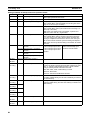
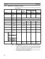
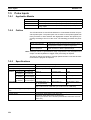
Pulse Inputs
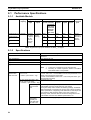
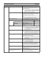
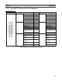
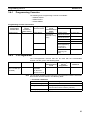
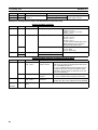
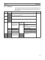
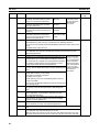
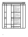
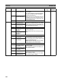
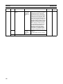
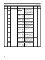
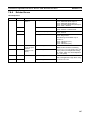
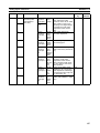
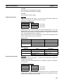
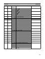
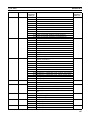
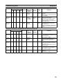
Item
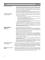
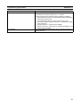
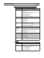
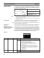
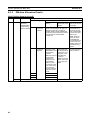
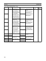
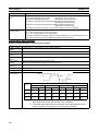
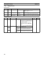
High-speed counter PV storage locations
Control
method
Specification
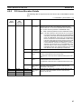
Port 1: AR 01 (upper bytes) and AR 00 (lower bytes)
Port 2: AR 03 (upper bytes) and AR 02 (lower bytes)
Target value or range comparison can be performed for the above values.
These values are updated during the I/O refresh period of the Customizable
Counter Unit. The stored data can be read using the PRV instruction.
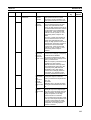
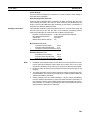
Stored Data (8-digit hexadecimal)
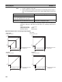
Linear Mode: 8000 0000 to 7FFF FFFF Hex
Ring Mode: 0000 0000 to Ring set value (Hex)
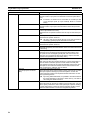
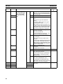
Up to 48 target values and interrupt subroutines registered.
Target value comparison
Range comparison
Counter reset
Up to 16 upper limits, lower limits, and output bit patterns registered.
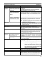
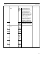
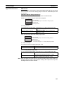
Phase Z Signal + Software Reset
The counter is reset on the phase-Z signal if the Reset Bit is ON.
Software Reset
The counter is reset when the Reset Bit is turned ON.
The counter reset methods is set in Unit Setup Area.
Reset Bit
Port 1: AR 0901, port 2: AR 0909
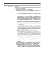
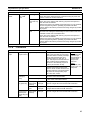
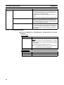
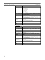
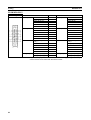
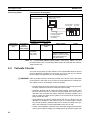
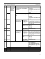
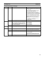
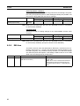
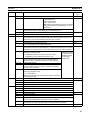
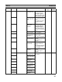
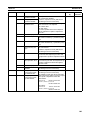
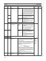
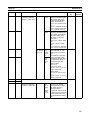
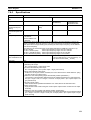
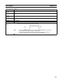
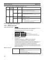
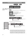
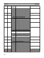
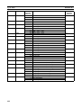
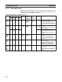
Measurement
mode
High-speed counter rate of
change for port 1 or 2
High-speed frequency for port 1
Measurement storage location
for above measurements
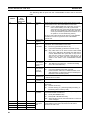
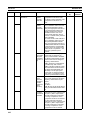
The change in the high-speed counter’s PV for the set sampling time or
each scan is measured.
Sampling time: 1 to 99 ms
Rate of change: 0000 0000 to FFFF FFFF Hex
The frequency is calculated from the PV between 0 and 200,000 Hz.
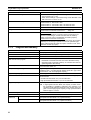
Port 1: AR 05 (upper bytes) and AR 04 (lower bytes)
Port 2: AR 07 (upper bytes) and AR 06 (lower bytes)
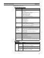
The high-speed counter value can also be read with the PRV instruction.
Stored Data
Rate of change: 8-digit hexadecimal
Frequency: 8-digit BCD
Updated during the I/O refresh period.
Measurement mode set in User Setup Area
(Port 1: Bits 00 to 03 of DM 6606; port 2: Bits 00 to 03 of DM 6608)
Measurement is started when the Measurement Start Bit (AR 0902 or AR 0910) is turned ON.
The Measuring Flag (AR 0806 or AR 0814) will turn ON during the measurement.
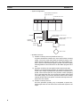
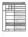
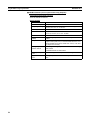
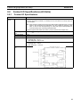
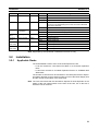
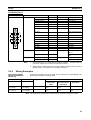
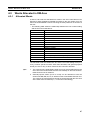
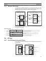
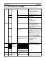
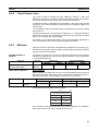
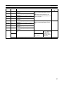
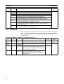
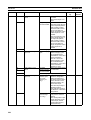
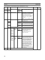
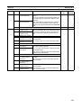
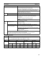
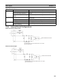
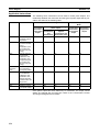
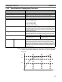
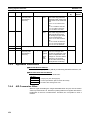
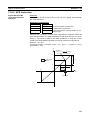
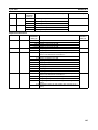
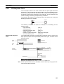
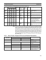
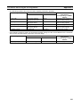
Pulse Input Specifications
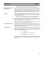
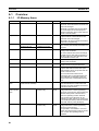
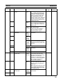
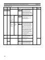
Item
Number of
pulse inputs
Signals
Specification
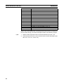
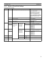
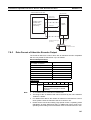
2 inputs (port 1 and port 2 = high-speed counter 1 and high-speed counter 2)
Port 1 is an RS-422A line driver input or an input voltage of 5 or 24 VDC.
Port 2 is an RS-422A line driver input or an input voltage of 5 or 12 VDC.
Encoder inputs A and B and pulse input Z
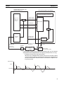
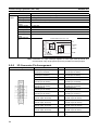
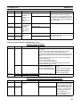
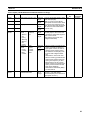
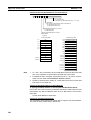
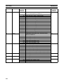
Ports
Port 1
Input voltage 5 VDC ±5%
Port 2
12 VDC ±10%
Ports 1 and 2
24 VDC ±10%
Ports 1 and 2
RS-422A line driver
(AM26LS31)
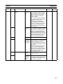
Phase Z
Phases A
and B
Phase Z
Phases A
and B
Phase Z
Phases A
and B
Phase Z
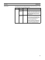
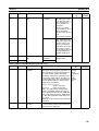
Input current 5 mA typ
ON voltage 4.5 V min.
7 mA typ
4.5 V min.
6 mA typ
8.8 V min.
10 mA typ
7.8 V min.
5 mA typ
19.6 V min.
8 mA typ
18.6 V min.
10 mA typ
---
13 mA typ
---
OFF voltage 1.5 V max.
1.3 V max.
2.4 V max.
2.0 V max.
4.0 V max.
4.0 V max.
---
---
Phases A
and B
127