1
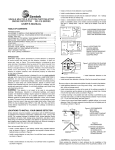
Installation Manual REW Solar Module
1. Purpose of this Manual
3.3 REW SOLAR® reserves the right to update the products, specification or this installation manual without no-
1.1 This manual contains information regarding the in-
tification in advance.
stallation and safe handling of photovoltaic modules
made by REW SOLAR®, which hereafter referred to as
4. Attention to unpacking and sto-
"modules".
ring modules
1.2 All instructions should be read and understood be-
Utmost attentions are required while unpacking & trans-
fore installation. The installer should conform to all safety
porting & storing the modules as following.
precautions in the manual when installing modules. Before installing a solar photovoltaic system, the installer
4.1 Don’t strike or physically damage the module.
should be familiar with the mechanical and electrical requirements for photovoltaic systems. Keep this guide in a
4.2 Carry modules with both hands. Don’t use the con-
safe place for future reference.
nection socket as a handle.
2. Permit
4.3 Don’t stand on the module.
2.1 Before installation your system, please contact local
4.4 Don’t twist the module.
authorities to determine the necessary permitting, installa4.5 Don’t mark on the rear of the module with sharp
tion and inspection requirement.
tools.
3. Disclaimer of liability
5. Safety Precautions
3.1 The installation, handling and use of modules are
beyond company control. Accordingly, REW SOLAR®
PV modules generate electricity when exposed to the
does not assume responsibility for loss, damage, injury
sunlight .One module produce a safe ,lower voltage
or expense resulting from improper installation handling,
level, but multiple modules in series or in parallel will
use or maintenance.
be danger. To avoid the risk of fire ,sparking and fatal
electric shock during handling, the following precautions
3.2 REW SOLAR® assumes no responsibility for any inf-
is necessary:
ringement of patents or other rights of the third parties that
may result from use of the modules. No license is granted
5.1 Don’t insert any electrically conducting material into
by implication or under any patents or its rights.
the plugs or sockets.
REW Solar® Auf dem Hövellande 6 | 44269 Dortmund, Germany
Phone: +49 231 - 58 44 93 - 0 | Fax: +49 231 - 58 44 93 - 20
E-Mail: [email protected] | Web: www.rewsolar.de
5.2 Don’t fit solar modules and wiring with wet plugs
7. Orientation:
and sockets.
7.1 Install the PV module facing South (in Northern He5.3 Make sure to use safety equipments (such as: insula-
misphere), or North (in Southern Hemisphere). Module
ted tools, insulated gloves, etc) during wiring.
facing West or East can generate a smaller amount of
electricity than facing South (in Northern Hemisphere), or
5.4 Make sure that the connection is made when the
North (in Southern Hemisphere). Incorrect orientation will
circuitry is cut off. Don’t disconnect under load.
result in loss of power output.
5.5 To prevent the electric arc, please ensure that the
7.2 PV modules connected in series should be installed
connectors is available (without any contamination and
in same orientation and angle. Different orientation or
worn out).
angle may cause loss of output power due to difference
of amount of sunlight exposed to the module.
6. Climate Condition
7.3 Install the PV as free as possible from shading. ShadInstall the PV modules as following conditions:
ing causes loss of output, even though the factory fitted
bypass diode of the PV module will minimize any such
6.1 Ambient temperature : -40°C to 40°C.
loss.
6.2 Operating temperature : -40°C to 85°C.
7.4 The PV modules connected in series should be installed at same orientation and angle. Different orientation
6.3 Storage temperature: -30°C to 50°C.
or angle may cause loss of output power due to difference of amount of sunlight exposed to the module.
6.4 Humidity: below 85RH%
7.5 The PV modules produce the most power when they
are pointed directly at the sun. For installations where
6.5 Snowfall pressure: below 5400Pa.
the PV modules are attached to a permanent structure,
the PV modules should be tilted for optimum winter per-
6.6 Wind pressure: below 3000Pa.
formance. As a rule, if the system power production is
6.7 Water resistance: don’t install the PV module in a
adequate in winter, it will be satisfactory during the rest
place where it would be immersed in water or continually
of the year. The module tilt angle is measured between
exposed to water from a sprinkler or fountain etc.
the solar modules and the ground (Figure 1). Optimal
tilting of PV module is almost the same as the latitude of
6.8 Corrosion resistance: far from corrosive salt area
installation location.
and sulfurous area.
REW Solar® Auf dem Hövellande 6 | 44269 Dortmund, Germany
Phone: +49 231 - 58 44 93 - 0 | Fax: +49 231 - 58 44 93 - 20
E-Mail: [email protected] | Web: www.rewsolar.de
8.6 Use the existing fixing holes instead of drilling additional holes for installation. The installa
and attachment material (nuts, washer, bolt) must be corrosion-resistant. Moments of force is 5N
for module mounting.
宁波尤利卡太阳能科技发展有限公司
8.7 The most common mounting is achieved by mounting the module using the four symmetry po
NINGBO ULICA SOLAR SCIENCE & TECHNOLOGY
CO.,
close to
theLTD.
inner side on module frame. If excessive wind or snow loads are expected, all e
mounting holes must be used.
Figure 1 PV Module Tilt Angle
Figure 1 PV Module Tilt Angle
Figure 2 PV module Mechanical drawing
Figure 2 PV module Mechanical1 drawing
中国·浙江省宁波市鄞州区望春工业园区杉杉路
号
邮编 PC:315177
No.1,Shanshan Road,Wangchun Industrial District, Ningbo, China,PC:315177
Tel: 86-574-28828976
Fax: 86-574-28828973
t and Notes:
propriate methods to mount PV modules. Fall of modules from high place will cause death,
8. Mount and Notes:
8.7 The most common mounting is achieved by mounting
amage.
disassemble, bend, impact by sharp objects, walk on, and throw or drop etc. the module using the four symmetry points close to the inconnect by demolishing or breaking the junction box, connector and guide wire. You’d
8.1 Use appropriate methods to mount PV modules. Fall
ner side on module frame. If excessive wind or snow loads
ow up the installation instruction to assemble module. When installing, the slope of module
of modules from high place will cause death, injury or
are expected, all eight mounting holes must be used.
less than 5 in/ft.
an choose thisdamage.
fix-up method to support the module as the least requirement.
module should be fixed by at least 4 points along the length of the frame.
8.8 REW SOLAR® PV modules can be mounted using the
e existing fixing holes instead of drilling additional holes for installation. The installation
following
methods:
Don’t
disassemble,
bend,
impact by sharp objects,
ment material8.2
(nuts,
washer,
bolt) must
be corrosion-resistant.
Moments of force
is 5N*m
e mounting. walk on, and throw or drop etc.
ost common mounting is achieved by mounting the module using the four symmetry points
(Note:allAlleight
installation methods herein are only for refehe inner side on module frame. If excessive wind or snow loads are expected,
holes must be8.3
used.
rence, and REW SOLAR® will not provide related BOS
Don’t connect by demolishing or breaking the junction box, connector and guide wire. You’d better follow
components, the system installer or trained professional
up the installation instruction to assemble module. When
personnel must be esponsible for the PV system’s design,
installing, the slope of module should be less than 5 in/ft.
installation, and mechanical load calculation and security of the system.)
8.4 You can choose this fix-up method to support the
− Using corrosion-proof screws (M8) in the existing instal-
module as the least requirement.
ling holes in the module frame.
8.5 Each module should be fixed by at least 4 points
Figure 2 PV module Mechanical drawing
along the length of the frame.
− Using suitable module clamps on the long side of the
·浙江省宁波市鄞州区望春工业园区杉杉路 1 号
邮编 PC:315177
module frame to mount the modules (“portrait orientation”)
hanshan Road,Wangchun Industrial District, Ningbo, China,PC:315177
8.6 Use the existing fixing holes instead of drilling additi6-574-28828976
Fax: 86-574-28828973
onal holes for installation. The installation and attachment
material (nuts, washer, bolt) must be corrosion-resistant.
Moments of force is 5N*m for module mounting.
REW Solar® Auf dem Hövellande 6 | 44269 Dortmund, Germany
Phone: +49 231 - 58 44 93 - 0 | Fax: +49 231 - 58 44 93 - 20
E-Mail: [email protected] | Web: www.rewsolar.de
1) Screw fitting: The frame of each module has 4 moun-
The movement of the mounting rail and the clamps center
ting holes (Length* Width: 18mm*9mm) used to secure
line are recommended to the mounting holes
the modules to supporting structure. The module frame
must be attached to a mounting rail using M8 corrosi-
8.7 To ensure the building safety, the recommended stan-
on-proof screws together with spring washers and flat
doff height is 20 cm. For rooftop installation, a minimum
washers in four symmetrical locations on the module. The
slope of 5cm/12 cm is required.
applied torque should be approximately 5 Newton-meters. Please find detailed mounting information
9. Grounding:
2) Clamp fitting (portrait orientation): Use a certain num-
Grounding is always to be used in order to improve sys-
ber of clamps to fix the modules on the mounting rail.
tem safety. The grounded connection must be made by a
The module clamps should not come into contact with the
qualified electrician as request following,
front glass and must not deform the frame. Be sure to avoid shadowing effects from the module clamps. The modu-
9.1 All module frames and its racks must be properly
le frame is not to be modified under any circumstances.
grounded in accordance with the appropriate respective
宁波尤利卡太阳能科技发展有限公司
NINGBO ULICA
SOLARpleSCIENCE &national
TECHNOLOGY
CO., LTD.
When choosing this type of clamp-mounting
method,
electrical
code.
ase be8.8
sure
to use
least four
on each
Ulica
PV at
modules
can clamps
be mounted
usingmodule,
the following methods:
(Note:
All
installation
methods
herein
are
only
and grounding
Ulica solar conductor
will not provide
9.2 The
or strap may be copper,
two clamps should be attached on the long sides of
thefor reference,
related BOS components, the system installer or trained professional personnel must be esponsible
copper alloy or other material acceptable for use as an
module. Depending on the local wind and snow loads,
for the PV system’s design, installation, and mechanical load calculation and security of the
electrical conductor per respective National Electrical
additionalsystem.)
clamps may be required to ensure the module
− Using corrosion-proof screws (M8) in the existing installing holes in the module frame.
Codes. The grounding conductor must make a conneccan bear the load. The applied torque should be about
− Using suitable module clamps on the long side of the module frame to mount the modules
tion to earth using a suitable earth ground electrode.
8 Newton-meters.
(“portrait orientation”)
1) Screw fitting: The frame of each module has 4 mounting holes (Length* Width: 18mm*9mm) used
to secure the modules to supporting structure. The module frame must be attached to a mounting rail
using M8 corrosion-proof screws together with spring washers and flat washers in four symmetrical
on the
module.with
TheScrew
applied
torque
should be approximately 5 Newton-meters. Please find
Figure locations
3 PV module
installed
fitting
method
detailed mounting information
Figure 3 PV module installed with Screw fitting method
2)Clamp fitting (portrait orientation): Use a certain number of clamps to fix the modules on the
mounting rail. The module clamps should not come into contact with the front glass and must not
deform the frame. Be sure toREW
avoid Solar
shadowing
® effects from the module clamps. The module frame
Auf dem Hövellande 6 | 44269 Dortmund, Germany
is not to be modified under any circumstances. When choosing this type of clamp-mounting
Phone:
+49
231 - 58
93 - should
0 | Fax:
method, please be sure to use
at least four clamps
on each
module,
two44
clamps
be+49 231 - 58 44 93 - 20
attached on the long sides of
the module. Depending
the local wind and| snow
additional
E-Mail:[email protected]
Web:loads,
www.rewsolar.de
clamps may be required to ensure the module can bear the load. The applied torque should be
宁波尤利卡太阳能科技发展有限公司
NINGBO ULICA SOLAR SCIENCE & TECHNOLOGY CO., LTD.
The movement of the
mounting rail and the clamps
center
line are recommended to the
mounting holes
Figure
4 atPV
module
installed
orientation
with
fitting
Figure 4 PV module
installed
portrait
orientation
withat portrait
10.3
Ensure that
all Clamp
materials
meet method
the requirements of
Clamp fitting method
the system maximum voltage, current, moisture and tem-
8.7 To ensure the building safety, the recommended standoff height is 20 cm. For rooftop installation,
perature when they are exposed to sunlight. Normally,
a minimum slope of 5cm/12 cm is required.
PV module is likely to produce more current and/or vol-
9. Grounding:
10. Wiring and Notes:
tage than that reported under Standard Test Conditions.
Grounding is always to be used in order to improve Accordingly
system safety.
grounded
connection
must
the The
values
of Isc and
Voc marked
on be
the
made by a qualified electrician as request following,
10.1 To minimize the risk of indirect lighting strike, avoid
module should be multiplied by a factor of 1.25 when
9.1 All module frames and its racks must be properly grounded in accordance with the appropriate
forming
closed loops
whenelectrical
designingcode.
the system. Check
selecting electrical components voltage rating, conductor
respective
national
that 9.2
wiring
correct before
starting the
fuseor
type,
and
type ofacceptable
control components
Theis grounding
conductor
or generator.
strap mayIfbethecopper,capacities,
copper alloy
other
material
for use
as
an
electrical
conductor
per
respective
National
Electrical
Codes.
The
grounding
conductor
must
measured open circuit voltage and short-circuit current
connected to the PV output.
a connection
to earth
using
earth ground electrode.
differmake
from the
specifications,
there may
beaasuitable
wiring fault.
11. Maintenance:
10.2 The plug connector has its own polarity. Make sure
that the connection is safe and tight. The plug connector
11.1 Check if mounting structure is loose. If necessary,
should not receive external trees. Connectors should only
please tighten the loose component again.
中国·浙江省宁波市鄞州区望春工业园区杉杉路 1 号
邮编 PC:315177
be used to connect the circuit. But never use to turn the
No.1,Shanshan Road,Wangchun Industrial District, Ningbo, China,PC:315177
circuit on or off.
Check connections of cables, grounding cables
Tel: 86-574-28828976
Fax: 11.2
86-574-28828973
and connectors periodically.
REW Solar® Auf dem Hövellande 6 | 44269 Dortmund, Germany
Phone: +49 231 - 58 44 93 - 0 | Fax: +49 231 - 58 44 93 - 20
E-Mail: [email protected] | Web: www.rewsolar.de
宁波尤利卡太阳能科技发展有限公司
NINGBO ULICA SOLAR SCIENCE & TECHNOLOGY CO., LTD.
Figure 5 Schematic drawing for PV module grounding
re 5 Schematic
drawing for PV module grounding
11.3 Often clean the face with soft cloth etc.
11.4 If changing one of module, the same kind and type
is needed.
11.5lighting
Don’t touch live
parts of cable
and connectors.
indirect
strike,
avoid
forming closed loops when designing the
Must use appropriate safety equipment (such as: insulacorrecttedbefore
starting the generator. If the measured open circuit voltage
tools, insulated gloves.
er from the specifications, there may be a wiring fault.
11.6 Strongly recommend covering the front surface
s its own
polarity. Make sure that the connection is safe and tight. The
of the PV module by an opaque cloth or other material
eceive when
external
trees.
Connectors
should only be used to connect the
repairing because
the PV
modules under the sunlight generate
highoff.
voltage and are danger.
the circuit
on or
als meet the requirements of the system maximum voltage, current,
when they are exposed to sunlight. Normally, PV module is likely to
voltage than that reported under Standard Test Conditions. Accordingly
marked on the module should be multiplied by a factor of 1.25 when
nts voltage rating, conductor capacities, fuse type, and type of control
PV output.
ture is loose. If necessary, please tighten the loose component again.
ables, grounding cables and connectors periodically.
h soft cloth etc.
REW Solar Auf dem Hövellande 6 | 44269 Dortmund, Germany
ule, the same kind and type
is needed.
Phone: +49 231 - 58 44 93 - 0 | Fax: +49 231 - 58 44 93 - 20
f cable and connectors. Must
use appropriate
safety
E-Mail: [email protected]
| Web:equipment
www.rewsolar.de (such as:
®