1
AD-4401
WEIGHING INDICATOR
1386-2A-IE
© 1998 A&D Company Ltd. All rights reserved.
No part of this publication may be reproduced, transmitted, transcribed, or translated into any
language in any form by any means without the written permission of A&D Company Ltd.
The contents of this manual and the specifications of the instrument covered by this manual are
subject to change for improvement without notice.
CONTENTS
CHAPTER 1 GENERAL DESCRIPTION...................................................................................... 3
CHAPTER 2 SPECIFICATIONS ................................................................................................... 4
2-1 A/D CONVERTER BLOCK ........................................................................................................ 4
2-2 DIGITAL BLOCK...................................................................................................................... 4
2-3 GENERAL SPECIFICATIONS ..................................................................................................... 4
2-4 ACCESSORIES ....................................................................................................................... 5
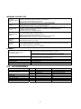
2-5 FRONT PANEL ....................................................................................................................... 6
2-6 REAR PANEL ....................................................................................................................... 10
CHAPTER 3 INSTALLATION AND CONNECTIONS ................................................................ 11
3-1 ENVIRONMENT..................................................................................................................... 11
3-2 POWER SUPPLY .................................................................................................................. 11
3-3 LOAD CELL.......................................................................................................................... 12
CHAPTER 4 OPERATION.......................................................................................................... 13
4-1 OPERATION MODE ............................................................................................................... 13
4-2 CONFIRMATION OF OPERATIONS .......................................................................................... 14
4-3 SETTING A SETPOINT ........................................................................................................... 15
CHAPTER 5 CALIBRATION ...................................................................................................... 18
5-1 GENERAL DESCRIPTION ....................................................................................................... 18
5-2 ACTUAL LOAD CALIBRATION (CAL SET)............................................................................... 19
5-3 CALIBRATION RELATED FUNCTIONS ...................................................................................... 20
5-4 CALIBRATION ERRORS ......................................................................................................... 24
5-5 INITIALIZATION OF ALL THE DATA .......................................................................................... 24
CHAPTER 6 GENERAL FUNCTIONS ....................................................................................... 25
6-1 BASIC CAPABILITIES RELATED .............................................................................................. 26
6-2 WEIGHING SEQUENCE RELATED........................................................................................... 28
6-3 CONTROL I/O INPUT RELATED .............................................................................................. 30
6-4 CONTROL I/O OUTPUT RELATED .......................................................................................... 30
6-5 STANDARD SERIAL OUTPUT RELATED .................................................................................. 31
1
CHAPTER 7 WEIGHING SEQUENCE ....................................................................................... 32
7-1 WEIGHING SEQUENCE................................................................................................... 32
7-2 CUSTOMER PROGRAMMED CONTROL MODE ......................................................................... 33
7-3 BUILT-IN AUTOMATIC PROGRAM MODE ................................................................................. 35
7-5 CHECK WEIGHING MODE ...................................................................................................... 43
7-6 COMPARISON WEIGHT ......................................................................................................... 51
7-7 AUTO PRINT ........................................................................................................................ 51
7-8 AUTOMATIC ACCUMULATION ................................................................................................. 51
7-9 AUTOMATIC FREE FALL COMPENSATION ............................................................................... 52
7-10 FUZZY AUTOMATIC FREE FALL COMPENSATION .................................................................. 52
CHAPTER 8 INTERFACE........................................................................................................... 53
8-1 CONTROL I/O ...................................................................................................................... 53
8-2 SETPOINT ........................................................................................................................... 56
8-3 STANDARD SERIAL OUTPUT (SER. OUT) ............................................................................. 57
CHAPTER 9 OPTIONS ............................................................................................................... 60
9-1 OP-01 PARALLEL BCD OUTPUT .......................................................................................... 60
9-2 OP-03 RS-422/-485 INTERFACE ......................................................................................... 62
9-3 OP-04 RS-232C INPUT/OUTPUTS ....................................................................................... 64
9-4 OP-05 SETPOINT UNIT ........................................................................................................ 70
9-5 OP-07 ANALOG OUTPUT ..................................................................................................... 73
CHAPTER 10 MAINTENANCE................................................................................................... 74
10-1 CHECK MODE .................................................................................................................... 74
10-2 INITIALIZATION ................................................................................................................... 76
CHAPTER 11 SETTING LISTS .................................................................................................. 77
11-1 GENERAL FUNCTIONS ........................................................................................................ 77
11-2 CALIBRATION RELATED FUNCTIONS .................................................................................... 83
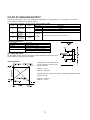
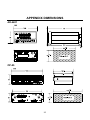
APPENDIX DIMENSIONS .......................................................................................................... 85
AD-4401 .................................................................................................................................. 85
OP-05 ...................................................................................................................................... 85
2
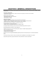
CHAPTER 1 GENERAL DESCRIPTION
The AD-4401 is a compact-weighing indicator equipped with high-performance A/D conversion and general-purpose capabilities. It has the
following features.
User-friendly cabinet design
• Small DIN size (panel dimensions: 138+1.0/-0 x 68+0.7/-0 mm) easy to mount in a control cabinet.
• Splash-proof front panel.
High-performance A/D Converter
• High-speed sampling, 100 times/second.
• High resolution, 1/16,000.
• High sensitivity, 0.3 µV/D.
Digital Span Capability
• Capable of calibration by inputting a mV/V value without an actual load.
• Capable of directly reading a load cell output (mV/V), for easy installation and maintenance.
• Replaceable without re-calibrating with an actual load in case of trouble.
Flexible Digital Filter allows installation in unstable environments
• Excellent vibration canceling performance.
• Widely covers from high-speed hopper scales to platform scales.
Two-stage Indicators monitoring Tare, Final, and Accumulated Weight values at any time.
Eight Weighing Modes available for wider applications
Capable of being used in a PLC-free hopper system owing to a complete weighing sequence.
• Built-in discharging sequence
• Monitors loading and discharging times
• Supplementary flow capability
Setpoints can be set using RS-232C/422/485 (Optional) as well as the front panel keys or an external thumbwheel
switch.
Control I/O providing a selection of the input/ output terminal capabilities and is available for any system.
High-speed, high-accuracy hopper scale based on Fuzzy Automatic Free Fall Compensation.
3
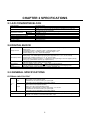
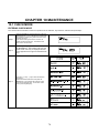
CHAPTER 2 SPECIFICATIONS
2-1 A/D CONVERTER BLOCK
Input sensitivity
Zero correction range
Load Cell Excitation
Temperature coefficient
Zero point
Sensitivity
Non-linearity
Maximum measurement voltage
Internal resolution
Maximum display resolution
Sampling speed
0.3 µV/D or more
0 to 20 mV ( 0 to 2mV/V)
10VDC +/- 5 %, 230 mA, with remote sensing capability (Up to eight 350
ohm load cells can be connected)
±(0.2 µV + 0.0008 % of Dead Load ) / °C typ
± 0.0008 % / °C typ
± 0.01%FS
32 mV (3.2 mV/V)
Approx. 1/1,000,000
16000
100 times/second
2-2 DIGITAL BLOCK
Display element
Main display section
Subdisplay section
Status display
section
Operational Keys
Fluorescent display tube (Display color: Cobalt blue, Status display in orange)
Display types;
1) Main display section: 7-segment 7-digit, Character height: 13 mm
2) Subdisplay section: 7-segment 8-digit, Character height: 7 mm
3) Status display: Up to 14 "-" marks are displayed
Switchable between net weight and gross weight
Display range: 0 to 16000D (Minimum division D is selectable out of 1, 2, 5, 10, 20, and 50)
Decimal point: Capable of setting 101, 102,103, and 104 digits
Overflow display: All digits turned off ("-" is displayed in the highest digit in case of negative polarity)
Units: g, kg, t (international version), kg, lb (USA version).
Tare, final, and accumulated weight values are selectable by the function. Also available for
Calibration setting, function setting, and error display.
Zero point, stability, gross, net, hold, , alarm, final, free fall, preliminary,
optional preliminary, overlimit, underlimit, and zero band depending on the weighing mode
SETPOINT, ZERO, TARE, NET/GROSS, F, ENTER, OPR/STB, CAL
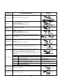
2-3 GENERAL SPECIFICATIONS
EXTERNAL INPUT/OUTPUT
Input
Control
I/O
Output
Standard serial output
Setpoint
6 points (6 bits, 1 COM)
Dry contact or open collector signal
Insulated from an internal circuit by an optocoupler.
*Terminal functions selectable by the function settings
8 points (8 bits, 1 COM)
Open collector output (NPN transistor)
Rating: 30 V DC, 50 mA (Resistance load)
Saturation voltage between a collector and emitter: 1.2 V or less
Insulated from an internal circuit by an optocoupler.
*Terminal functions selectable by the function settings
Output for our peripheral device connection (0 to 20 mA current loop signal)
Changes setting of each setpoint, using a thumbwheel switch. Capable of connecting an OP-05
setpoint unit in addition to the thumbwheel switch. Input
4
WEIGHING CAPABILITIES
Zero point
correcting capability
(Zero)
Zero tracking
capability
Tare subtracting
function
Stability detecting
capability
Clears the gross to zero in compliance with a command from the ZERO keys, Control I/O, etc.
Capable of enabling or disabling operations at unstable time.
Zero correction value is backed up by a battery.
Adjustable range: Can be freely set within 1 to 30 % of weighing capacity.
Detects gross zero point drift and performs zero correction automatically.
Tracking time: 0.0 to 5.0 (seconds)... A range can be set freely
Tracking width: 0.0 to 4.5 (D) ... A range can be set freely
Clears the net weight zero in compliance with a command from the TARE key, Control I/O, etc.
Capable of enabling or disabling operations at unstable time or negative weight time.
The battery backs up a tare value.
Adjustable range: gross ≤ Weighing capacity
When a weighed value fluctuation amount per sampling enters a set width within a set time, a stability
mark is illuminated, judging it a stable condition.
Capable of confirming stability through Control I/O.
Stability detection time: 0.1 to 5.0 (seconds) ... A range can be set freely
Stability detection width: 0 to 9 (D) ... A range can be set freely
Digital filter function
Integrating
capability
Two digital filters connected in series
Cutoff frequency range: 0.7 to 11 (Hz)
Integrating
capability
Integrates the net weight automatically or manually.
An accumulated weight and the number of accumulated weighing times are backed up by the battery.
Accumulated weight range: 0 to 99999999
Accumulated weighing times range: 0 to 99999999
OVERALL
Power failure countermeasure
Data backup method
Supply voltage
Power consumption
Working temperature and humidity range
Mounting method
Weight (accessories not included)
Zero point correction value, tare value, setpoint, accumulated weight
Memory backup by the lithium battery (Approx. 10 years)
An alarm indicator lamp is turned on when the battery is running out.
Calibration data, each function data
Writes into the non-volatile memory(EEPROM).(Up to 10,000 times)
100 to 120 VAC +10%/-15%, 50 Hz or 60 Hz
200 to 240 VAC +10%/-15%, 50 Hz or 60 Hz
Approx. 30 VA
-5 to +40 °C, 20 to 85 % R.H
Panel mounting type
Approximately 1.3 kg
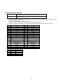
2-4 ACCESSORIES
Parts Name
Fuse
Connector for Control I/O
Connector for standard serial output
Capacity plate
Unit label
Panel mount packing
Terminal block cover
Rubber leg
Q'ty
1
1
1
1
1
1
1
1
4
A&D’s parts Number
FS-EAK-1A
JI-361J016-AG
JI-360C016-B
JA-TCP0576
5
Description
EAK-1A (Time lag fuse, 1 A)
FCN361J016-AG (FUJITSU)
FCN360C016-B (FUJITSU)
TCP0576 (HOSHI ELECTRIC)
N/A
N/A
N/A
N/A
N/A
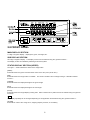
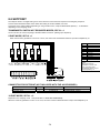
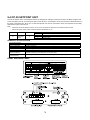
2-5 FRONT PANEL
MAIN DISPLAY SECTION
A 7-digit 7-segment display. Displays the gross, net weight, etc.
SUB DISPLAY SECTION
An 8-digit 7-segment display. The display content can be selected using the “general functions.”
The display content is indicated by attaching an accessory label.
STATUS DISPLAY SECTION (UPPER)
The upper “-” mark indicates the status of the weight value.
[ZERO]
Illuminated when the gross is located at the center of the zero point (center zero).
[MD]
Illuminated when the weight value is unstable. The motion condition can be changed using a " calibration related
function."
[GROSS]
Illuminated when the displayed weight is the gross weight.
[NET]
Illuminated when the displayed weight is the net weight.
[HOLD]
Illuminated when the weight display is being held. Either normal hold or peak hold can be selected using the "general
functions."
[
]
This display capability can be changed depending on the application and selected using the “general functions.”
[ALARM]
Illuminated in case of zero range error, weighing capacity overflow, or low battery.
6
STATUS DISPLAY SECTION (LOWER)
The lower “-” mark indicates a comparison result.
In the normal mode, it is illuminated when a setpoint output of an identical name is turned on. In the setpoint setting
mode, the “-” mark relevant to the value in the lower numerical display section blinks. Attach an accessory label
depending on the weighing mode.
< Normal Batching >
[FINAL]
Blinks while setting the final weight.
Normal batching —— Illuminated when the net weight is within a positive range.
[F. FALL]
Blinks while setting the free fall.
Normal batching —— Illuminated when the net weight is more than the final weight minus free fall.
Built-in-automatic program mode —— Illuminated during dribble flow.
[PRELIM]
Blinks while setting the preliminary.
Normal batching —— Illuminated when the net weight is more than the final weight minus preliminary.
Built-in-automatic program mode —— Illuminated during medium flow.
[OP PLM]
Blinks while setting the optional preliminary.
Normal batching —— Illuminated when the net weight is more than the final weight minus optional preliminary.
Built-in-automatic program mode —— Illuminated during full flow.
[OVER]
Blinks while setting the overlimit.
Illuminated when the net weight is more than the final weight plus overlimit.
[UNDER]
Blinks while setting the underlimit.
Illuminated when the net weight is less than the final weight minus underlimit.
[ZERO BAND]
Blinks while setting the zero band.
Illuminated when the gross weight is less than the zero band.
< Loss-in-weight >
Attach a label that has “OPTIONAL PRELIMINARY replaced by “FULL.” The other operations are the same as normal
batching.
[FULL]
Blinks while setting the full weight./ Illuminated when the gross weight is more than the full weight.
7
< Check Weighing >
The meaning of each “-” mark differs completely. Attach a different accessory label. There are four kinds of Check
Weighing.
[Z.BAND]
Illuminated when the gross weight is less than the zero band.
[Lo-Lo]
Blinks while setting the Lo-Lo.
Illuminated when the comparison result output, Lo-Lo, is turned on.
[Lo]
Blinks while setting the Lo limit.
Illuminated when the comparison result output, Lo, is turned on.
[Go]
Blinks while setting a reference value.
Illuminated when the comparison result output, Go, is turned on.
[Hi]
Blinks while setting the Hi limit.
Illuminated when the comparison result output, Hi, is turned on.
[Hi-Hi]
Blinks while setting the Hi-Hi limit.
Illuminated when the comparison result output, Hi-Hi, is turned on.
8
KEY SWITCHES
[CAL]
The key used to enter the calibration mode. A cover is provided so that this key can not be operated if used in a certified
commercial application. In order to prevent erroneous operation, attach and seal the cover.
[SETPOINT]
The key used to set a setpoint. If this key is pressed together with the [ENTER] key, you will enter the “general function”
mode.
[ZERO] ([<])
The key used for zeroing. A zeroing condition can be set with the “calibration related functions. ” While inputting a
number, this key is used to shift the blinking digit to the left.
[TARE] ([>])
The key used to subtract the tare. The tare subtraction condition can be set with the “calibration related functions.”
While inputting a number, this key is used to shift the blinking digit to the right.
If the [ON/OFF] key is pressed together with this key in the OFF mode, the zero compensation value and the tare value
will be cleared.
[GROSS/NET] ([^])
The key used to switch the weight display from gross weight to net weight and vice versa. While inputting a number,
pressing this key will increase the number of the blinking digit by one.
[F] ([V])
The capability of this key can be changed depending on the application. The following capabilities can be selected using
the “general functions.”
No capability (Setting upon shipment)
Print command for manual print
Hold
Batch Start
Emergency stop
Clear to zero
Clear tare
Clear accumulation
While inputting a number, pressing this key decreases the number of the blinking digit by one.
[ENTER]
While inputting a number, pressing this key writes that number into memory.
[OPR/STB] ([ESC])
The key used to switch from the normal mode (ON state) to the standby mode (OFF state) and vice versa. In the
standby mode, all displays and external inputs/outputs are turned off and a circle (O) appears in the unit display section.
While inputting a number, this key serves as the [ESC] (Escape) key.
TOP OF FRONT PANEL
The top of the front panel has a concave area for attaching a weighing capacity nameplate.
,+.*
/-,*
9
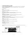
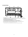
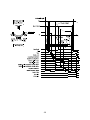
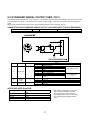
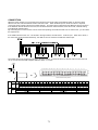
2-6 REAR PANEL
(a) Connects the thumbwheel switch or setpoint unit (OP-05) to set a setpoint required for a weighing sequence.
See 8-2 and 9-4.
(b) Inputs/outputs the signals such as tare subtraction input, each loading output required for the weighing sequence.
The capability of each terminal can be changed freely. See 8-1.
(c) Provides an output for the standard serial interface (current loop).
(d) One of the following options can be attached;
OP-01 BCD output, OP-03: RS-422/-485 input/output, OP-04: RS-232C input/output
(e) Connects to the power source. Confirm the description on the supply voltage label. See 3-2.
(f) Provides an analog output if option OP-07, analog output, is attached. Use a shielded cable for wiring.
(g) Connects to the load cell. Use a shielded cable for wiring. See 3-3.
Be sure to attach a cover to the terminal block on the rear panel in order to prevent an accident.
10
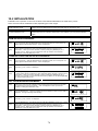
CHAPTER 3 INSTALLATION AND CONNECTIONS
This chapter describes the installation environment, and connections to the power terminals and load cell connector. For
other external inputs/outputs, see their relevant descriptive chapters.
Control I/O, Setpoint (SETPOINT), Standard serial output (SER. OUT) —— Chapter 8
Options —— Chapter 9
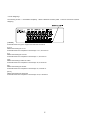
3-1 ENVIRONMENT
,017694
,0938
+<623 -068
This is a precision electronic instrument. Handle it very carefully.
working temperature range is -5 to +40°C. Install it in a place free
the direct sunlight. When water drops may splash over the
instrument, attach it to a control panel, using the accessory
packing. This makes the instrument's front panel splash-proof.
/0;53:
.1:3=
The
from
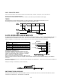
3-2 POWER SUPPLY
1) Prior to connecting the power source, read this manual thoroughly.
2) Be sure to earth ground the instrument. Use independent grounding if possible. Try not to share grounding with
other electric devices that create electrical noise.
3) The power source should be either 100 to 120 VAC +10%/-15% specification, or 200 to 240 VAC +10%/-15%
specification; with a frequency of 50 or 60 Hz. Use a stable power source free from instantaneous dropout or
noise. Sharing a power line could result in malfunctioning.
4) The load cell output is very weak. Do not install any noise-generating device near the load cell or the load cell
cables.
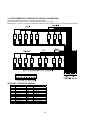
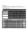
5) Each input/output cable should be shielded and connected to either shield terminal 7 or 10 of the terminal strip on
the rear of the indicator. Use of terminal 11 or the indicator body, could induce electrical noise.
Terminal No.
1
2
3
4
5
6
7
8
9
10
11
12
13
Terminal Function
EXC+
Load cell excitation voltage (+)
SEN+
Sensing input (+)
SENSensing input (-)
EXCLoad cell excitation voltage (-)
SIG+
Load cell input (+)
SIGLoad cell input (-)
SHLD
Shield
A+
4 to 20 mA output (+)
A4 to 20 mA output (-)
SHLD
Shield
E
FG
AC
AC power supply
AC
AC power supply
Load cell Connections
OP-07
11
6) To change a blown fuse.
Turn the power off and wait 10 seconds or more. Replace the
fuse with the accessory fuse without touching other parts.
Make sure that no stray material is left in the case, screws,
spacer, etc., before closing the case.
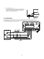
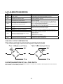
3-3 LOAD CELL
For a load cell cable, the use of a 6 wire shielded cable is recommended in order to reduce weighing error.
When using a 4 wire cable, connect pin no. 1 to no. 2 (load cell applied voltage + and sensing input +), and pin no. 3 to
no. 4 (load cell applied voltage - and sensing input -).
12
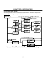
CHAPTER 4 OPERATION
4-1 OPERATION MODE
This instrument has various “modes” in compliance with its operating conditions. Use the keys to change the mode.
You can change the mode in the full-line arrow direction. The broken-line arrow direction indicates only an automatic
reset after completion of setting or a reset by turning off the power.
.
13
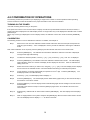
4-2 CONFIRMATION OF OPERATIONS
The following outlines the procedure up to displaying a weight value in order to confirm operations after unpacking.
Connect a load cell or load cell simulator to the proper terminals on the rear of the indicator.
TURNING ON THE POWER
* Do load cell wiring before turning on the power.
If the power is turned on in the normal mode, the display unit will be fully illuminated for about 2 seconds, and then, a
weight value will be displayed in the main display section. A weight value may not be displayed if calibration has not been
performed yet.
When only a circle (O) is displayed in the unit display section, the indicator is in the OFF mode. Press the [OPR/STB]
key.
CALIBRATION
The following outlines on how to calibrate the indicator. For details, see Chapter 5.
Step 1
Remove the cover from the calibration switch located at the lower left of the front panel and press the
[CAL] key (found inside). “CAL” is displayed to inform you that the indicator is entering the calibration
mode.
Note: When calibration is not required, press the [ESC] key and the indicator will return to the normal mode.
Step 2
Press the [ENTER] key. The indicator has entered the calibration mode and “CAL SEt” is displayed.
The right most digit starts blinking.
Step 3
To select the desired operation, use the [ ∧ ] or [ ∨ ] key, Press the [ ∧ ] key, “CAL Fnc” is displayed.
Step 4
Press the [ENTER] key. The indicator enters the calibration related function mode. The main display
section displays “CALF-01” and the sub-display section displays its set value. CALF-01 indicates the
setting of the unit.
Step 5
Select the function number you want to set, using the [ ∧ ] or [ ∨ ] key. The lower display section displays
the set value for the selected function. CALF-02 indicates the setting of a decimal point position.
Step 6
In this example, you change the decimal point position to the 101 digit. Press the [ENTER] key. The
Subdisplay section now starts blinking.
Step 7
Press the [ ∧ ] key. The Subdisplay section displays “1”.
Step 8
Press the [ENTER] key. The main display section starts blinking again and you are returned to Step 5,
the selection of a function number.
Step 9
Press the [ESC] key. The main display section starts blinking again and the settings so far are saved in
the EEPROM.
This state is the same as in Step 3. Press the [ESC] key again twice. The indicator will return to the
normal mode.
Step 10
Subsequently, calibrate with an actual load. Press the [ENTER] key. The main display section displays
“CAL 0.”
Step 11
With no weight placed on the system and press the [ENTER] key after the motion-detect mark is turned
off. The Subdisplay section displays “——” for about 2 seconds.
14
Step 12
The main display section displays “CAL SPn”, the Subdisplay section displays a weight value (current
weighing capacity, set value for CALF-04), and the lowest digit of the weight value blinks. Adjust to the
calibration weight value that you have on hand, using the [<], [>], and [ V ] keys.
Step 13
Place the weight on the system, and press the [ENTER] key after the motion-detect mark is turned off.
The Subdisplay section displays “——” for about 2 seconds.
Step 14
The main display section displays “CAL End.” If “C ErrXX” has been displayed so far, there is an error
taking place. See 5-5.
Step 15
Press the [ESC] key. The main display section displays “CAL SEt” and the actual load calibration data is
saved in the EEPROM.
Step 16
This state is the same as in Step 3. Press the [ESC] key again twice. The indicator will return to the
normal mode.
The normal mode is restored and the weight value is displayed.
After calibration is finished, be sure to attach the [CAL] key cover.
4-3 SETTING A SETPOINT
The setpoint refers to a weight setting such as a target weight or final weight required for a weighing sequence. The
following describes how to set the setpoint. For the details of the thumbwheel switches, see 8-2.
The following four methods are available for setting the setpoint:
1. Setting with the key switches (Thumbwheel switch not required)
2. Setting with a 5-digit thumbwheel switch
3. Setting with a 16-digit thumbwheel switch or OP-05 setpoint unit
4. Setting with the RS-232C/-422/-485 (See 9-2, 9-3)
Select one of the above-mentioned methods in the “setpoint read mode (SPF-01)” of the general functions.
All of the setpoint settings are backed up by the memory battery and held even if the power is turned off.
The setpoint differs depending on the weighing mode. When the weighing mode (CALF-14) is changed, attach a
relevant accessory label onto the specified area of the front panel. The following describes the initial setting state and no
label is required to be attached.
15
SETTING WITH THE KEY SWITCH (SPF-01 = 0)
This method sets the setpoint using only the keys on the front panel.
Step 1
Press the [SETPOINT] key in the normal mode. The indicator will switch to the setpoint setting mode.
The “-” mark above FINAL in the Subdisplay section blinks and a final value is displayed.
• Operating the [SETPOINT] key allows you to refer to other setpoints.
• Operating the [<] or [>] key also allows you to refer to the setpoint.
• If the [SETPOINT] key is pressed while the right end (ZERO RANGE) is being displayed, you will be
returned to the normal mode.
• Pressing the [ESC] key returns you to the normal mode at any time.
Step 2
Press the [ENTER] key. The blank digits of the Subdisplay section are filled with the character “0”.
A cursor appears at the lowest digit and the right most digit starts blinking.
Step 3
Rewrite the set value, using the [<], [>], and [ V ] keys
• In this example, the set value has not been saved internally.
• When you want a negative set value in Check Weighing, and so on, move the cursor to the left end and
use the [ V ] key to decrement 0.
Step 4
Press the [ENTER] key. The set value is saved internally. Surplus zeros and the cursor disappear.
• This state is the same as in Step 1.
• To return to the normal mode, press the [ESC] key.
SETTING WITH A 5-DIGIT THUMBWHEEL SWITCH (SPF - 01 = 1)
In the normal mode, the 5-digit thumbwheel switch is read as the final value in real time. Using this thumbwheel switch,
you can set other setpoints.
When the setting of the minimum graduation (CALF-03) is 10 or more, the value of the thumbwheel switch is multiplied by
10 when saved.
Step 1
Press the [SETPOINT] key in the normal mode. The indicator will switch to the setpoint setting mode.
The “-” mark above FINAL in the Subdisplay section blinks and a final value is displayed.
• Operating the [SETPOINT] key allows you to refer to other setpoints.
• Operating the [<] or [>] key also allows you to refer to the setpoint.
• If the [SETPOINT] key is pressed while the right end (ZERO RANGE) is being displayed, you will be
returned to the normal mode.
• Pressing the [ESC] key returns you to the normal mode at any time.
Step 2
In this example, a free fall is set. Press the [SETPOINT] key. The “-” mark above FREE FALL blinks and
a free fall value is displayed.
Step 3
Change the thumbwheel switch to the desired value and press the [ENTER] key. The value of the
thumbwheel switch is saved internally as the free fall.
• This state is the same as in Step 1. To return to the normal mode, press the [ESC] key.
Note: Prior to returning to the normal mode, be sure to return the value of the thumbwheel switch
to the final value.
16
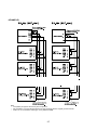
SETTING WITH THE 16-DIGIT THUMBWHEEL SWITCH (SPF - 01 = 2)
This method assigns an exclusive thumbwheel switch to each setpoint. Some setpoints are set with the front panel keys
without using the thumbwheel switch.
Assignment of the thumbwheel switch and the front panel keys differs depending on the weighing mode (CALF-14)
Since the setpoint assigned to the thumbwheel switch is read in real time, it can be referred to by key operation, but it
cannot be altered. The following shows assignment of the setpoints.
Normal Batching (Customer Programmed Control Mode)
Normal Batching (built-in Automatic Program Mode)
(CALF-14=1)
(CALF-14=3)
For the thumbwheel switches
Final (5 digits), Free Fall (3 digits), Preliminary (4 digits) Over Limit (2 digits),
Under Limit (2 digits)
For the key switches
Option Prelim, Zero Band
Loss-in-weight (Customer Programmed Control Mode)
Loss-in-weight (built-in Automatic Program Mode)
(CALF-14=2)
(CALF-14=4)
For the thumbwheel switches
Final (5 digits), Free Fall (3 digits), Preliminary (4 digits)
Over Limit (2 digits), Under Limit (2 digits)
For the key switches
Full, Zero Band
Check Weighing Mode 1
Check Weighing Mode 2
For the thumbwheel switches
For the key switches
Check Weighing Mode 3
(CALF-14=5)
(CALF-14=6)
Lo (5 digits), Hi (5 digits)
Zero Band, Lo-Lo, Hi-Hi
(CALF-14=7)
For the thumbwheel switches
Lo-Lo (4 digits), Lo (4 digits), Hi (4 digits), Hi-Hi (4 digits)
For the key switches
Zero Band
Check Weighing Mode 4
(CALF-14=8)
* For setting with the front panel keys, see “Setting with the Key Switches (SPF - 01 = 0).”
* When the minimum graduation setting (CALF-03) is 10 or more, 10 will multiply the value set with the thumbwheel
switch.
17
CHAPTER 5 CALIBRATION
5-1 GENERAL DESCRIPTION
In the calibration mode, you carry out an operation, which associates a load cell output voltage with a weight value, and
operations directly related to weighing. There are the following four kinds.
Actual load calibration
Calibration Modes:
Calibration related functions
Digital span
Initialization of all data
This is calibration with weights.
[Zero calibration]
The zero point is measured with no weight loaded.
[Span calibration] The full weighing capacity point is measured with a calibration
Actual load calibration
weight loaded.
• Once in the calibration mode, the tare value and zero compensation value are
cleared automatically.
Calibration related
They set the data directly related to weighing as well as basic constants for the
functions
weighing instrument such as minimum graduation, weighing capacity, and so on.
The zero point and span are set by entering the load cell output (mV/V) using the keys.
No calibration weight is loaded. (CALF-15 ~ CALF-17 of the Calibration related
functions,)
• [Zero calibration]
Enter the load cell output at the zero point.
Digital span
• [Span calibration]
Enter the difference of the load cell output between at
the full weighing capacity and at the zero point.
• Weight to Span calibration Relate the input voltage at [Span calibration] above with
weight to be displayed.
Initialization of all data
All the data of the EEPROM and RAM are initialized.
• All the data set in calibration is saved in the EEPROM and held even if the backup battery is fully discharged.
• Do the all load cell wiring before turning the power on. Calibration may be failed if wired after turned on.
18
5-2 ACTUAL LOAD CALIBRATION (CAL SET)
The zero point and span are calibrated using a calibration weight. When making calibration for the first time, it is
necessary to set the unit, decimal point position, minimum division, and capacity in advance, using the calibration-related
functions mentioned in 5-3.
In order to avoid influence by temperature drift; carry out this calibration 10 minutes or more after turning on the power.
Step 1
•
Remove the cover from the calibration switch located at the lower left of the front panel and press the
[CAL] key (found inside). “CAL” is displayed to inform you that the indicator is entering the calibration
mode.
Note: When calibration is not required, press the [ESC] key. The indicator will return to the normal mode.
Step 2
Press the [ENTER] key. The indicator has entered the calibration mode and “CAL SEt” is displayed.
The right most digit starts blinking.
ZERO CALIBRATION
Step 3
Press the [ENTER] key. The main display section displays “CAL 0.”
When you want to monitor the current weight value, press the [SETPOINT] key. The Subdisplay section
displays the value. Pressing the [SETPOINT] key again erases this display.
When zero calibration is not necessary, press the [F] key. The indicator will go to span calibration
(Step 5).
Step 4
•
With no weight placed on the system, press the [ENTER] key after the motion-detect mark is turned off.
The Subdisplay section displays “——” for about 2 seconds.
When “C ErrXX” is displayed, there is an error taking place. See 5-4.
SPAN CALIBRATION
Step 5
The main display section displays “CAL SPn,” the Subdisplay section displays the weight value (current
weighing capacity, set value for CALF-04), and the lowest digit of the weight value blinks. Adjust to the
calibration weight value that you have on hand, using the [<], [>], [ ∧ ] , and [ ∨ ] keys.
When you want to monitor the current weight value, press the [SETPOINT] key. The Subdisplay section
displays the value. Pressing [SETPOINT] again replaces this display with the weight value.
When span calibration is not necessary, press the [ESC] key twice. You are returned to the normal mode.
Step 6
•
Place the calibration weight on the system and press the [ENTER] key after the motion-detect mark is
turned off.. The Subdisplay section displays “——” for about 2 seconds.
When “C ErrXX” is displayed, there is an error taking place. See 5-4.
Step 7
The main display section displays “CAL End.”
When you want to readjust the span, press the [F] key. This will allow you to continue span calibration.
Step 8
Press the [ESC] key. The main display section displays “CAL SEt” and the actual load calibration data is
saved in the EEPROM.
Step 9
This state is the same as in Step 3. Press the [ESC] key once again. The indicator will return to the
normal mode and the weight value is displayed.
19
5-3 CALIBRATION RELATED FUNCTIONS
The calibration related functions are designed to set the basic constants for the indicator. They should be carried out first
thing upon installation.
Step 1
Remove the cover from the calibration switch located at the lower left of the front panel and press the
[CAL] key (found inside). “CAL” is displayed to inform you that the indicator is entering the calibration
mode.
Step 2
Press the [ENTER] key. The indicator switches to the calibration mode and “CAL SEt” is displayed. The
right most digit starts blinking.
Step 3
Press the [] key. “CAL Fnc” is displayed.
Step 4
Press the [ENTER] key. The indicator switches to the calibration related function mode. The main
display section displays “CALF-01” and the Subdisplay section displays its set value. CALF-01 is the
function for the setting of the unit.
Step 5
Select the function number you want to set, using the [<], [>], [ ∧ ] , and [ ∨ ] keys. The display section
displays a set value for the selected function. In this example, select CALF-02 to set the decimal point
position.
Step 6
In this example; you change the decimal point position to the 101 digit. Press the [ENTER] key. The
Subdisplay section now starts blinking.
Step 7
Press the [] key. The Subdisplay section displays “1”.
Step 8
Press the [ENTER] key. The main display section starts blinking again and you are returned to selection
of the function number (Step 5).
Step 9
Press the [ESC] key. “CAL SET” is displayed and the settings so far are saved in the EEPROM.
Step 10
This state is the same as in Step 3. Press the [ESC] key once again. The indicator is return to the normal
mode.
The normal mode is restored and the weight value is displayed.
•
•
When “Err” is displayed, the value input exceeds the setting range.
When “C ErrXX” is displayed, there is an error taking place. See 5-4.
20
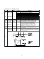
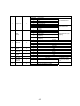
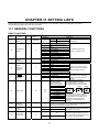
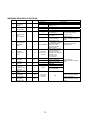
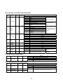
CALIBRATION RELATED FUNCTIONS
Setting
CALF-
Name
01
Weighing Unit
2
02
Decimal Point
Position
0
Default
Parameter
0
1
2
3
4
0
1
Description
None
g (International version)
kg ( International version and USA version)
t (International version)
lb. ( USA version)
None
12345
1
1234.5
10
2
2
10
3
10
4
1, 2, 5, 10,
20, or 50
03
Minimum
Division
1
04
Capacity
16000
0 to 800000
05
Zero Range
2
0 to 30
06
Zero Tracking
Time
0.0
0.0 to 5.0
Zero Tracking
Width
0
0 to 9
3
4
123.45
12.345
1.2345
10
Minimum division (increment) for the weight value.
Input 1,2, 5, 10, 20, or 50(decimal point ignored).
Capacity of the weighing. Weighing is allowed up to this
setting + 9D(9 divisions). A weight value beyond this limit
is an overflow and not displayed.
A range of accepting "zero" from the [ZERO] key or
Control I/O. Represented in terms of percent(&) with
respect to the weighing capacity, centering around the zero
calibrated point in calibration. If this is set to 2, "zero" can
be accepted within a range of the zero calibrated point
+/- 2 %.
Zero tracking is performed in combination with CALF-07
Zero Tracking Width. It is not performed when set to 0.0.
Its unit is seconds
Zero tracking is performed in combination with CALF-06 Zero
Tracking Time. It is not performed when set to 0. Its least input
increment is 1/2D. (The width for setting of 1 is equivalent to 1/2 of
the minimum graduation)
07
21
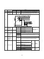
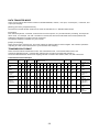
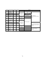
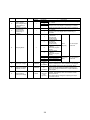
CALF08
Name
Motion
Detection Time
Motion
Detection
Range
Setting
Default
Parameter
1.0
0.0 to 5.0
2
0 to 9
Description
Motion is detected in combination with CALF-09 Motion Detection
Width. It is not detected when set to 0. Its unit is seconds.
Motion is detected in combination with CALF-08 Motion Detection
Time. Its least input increment is 1D. (The range for setting of 1
is equivalent to the minimum division)
09
10
11
12
13
0
Tare and Zero
at Unstable
Weight Value
1
Tare at
Negative gross
1
Standard Serial
Output; Output
When Weight
Value Is
Overflowing or
Unstable
RS-232C/-422/485; Output
When Weight
Value Is
Overflowing or
Unstable
1
0
1
1
0
1
0
1
1
3
Does not output when the weight value is overflowing or unstable
Outputs even if the weight is overflowing or unstable
Does not output when the weight value is overflowing or unstable.
1
Outputs even if the weight value is overflowing or unstable
2
Weighing Mode
Not available on the
USA version.
0
1
14
"Tare" is not accepted when the weight
value is unstable.
"Tare" is accepted even if the weight
value is unstable.
"Tare" is not accepted when the gross
weight is negative.
"Tare" is accepted even if the gross
weight is negative.
3
4
5
6
7
8
Normal batching
(Customer programmed control
mode)
Loss-in-weight
(Customer programmed control
mode)
Normal batching
(Built-in automatic program mode)
Loss-in-weight
(Built-in automatic program mode)
Check weighing 1
Check weighing 2
Check weighing 3
Check weighing 4
22
Batch
Weighing
For the
hopper
scale use
Check
Weighing
For the
platform
scale use
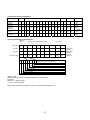
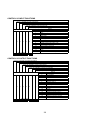
15
Zero Input
Voltage
0.000000
0.000000
to
2.200000
Input Voltage (mV/V) from the Load Cell at "Zero",
which is determined in "Zero Calibration" with weights.
16
Span Input
Voltage
(Capacity to
zero)
3.200000
0.000000
to
3.200000
Input Voltage (mV/V) from the Load Cell at "Span",
which means the difference between Capacity and
Zero. The voltage is determined in "Span Calibration"
with weights.
17
Weight against
Span Input
Voltage
16000
0 to 800000
(decimal point ignored)
When "Digital-Calibration", calibration not using
weights, is performed, CALF-15 and CALF-16
also have to be done.
This setting will be changed to Capacity (CAL-04) if
"CAL Set" is done.
Note: Write down the value of CALF-15, and
CALF-17 on the setting list attached back of this
manual for the maintenance purpose.
(Accuracy at replacement: approximately 1/500)
The scale can be calibrated with the stored
value, CAL-15,CALF-17. (Digital span function
approximately 1/1000) However it is
recommended to use weights for a better
accuracy.
23
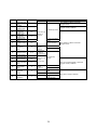
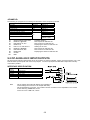
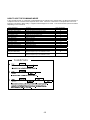
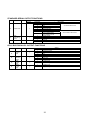
5-4 CALIBRATION ERRORS
Err
messages
CErr 0
CErr 1
CErr 2
CErr 3
CErr 4
CErr 5
CErr 6
Causes
The minimum graduation is other than 1, 2, 5,
10, 20, and 50.
Resolution (weighing capacity/minimum
graduation) is more than 16000.
The voltage of the zero calibration point is
overloaded in the positive direction.
The voltage of the zero calibrated point is
overloaded in the negative direction.
The calibration weight is more than the weighing
capacity.
The calibration weight is less than the minimum
graduation
Sensitivity of the load cell is insufficient.
CErr 8
The output voltage of the load cell is too high
with the span capacity loaded,
CErr 7
The voltage of the span calibration point is
negative with respect to the zero point.
Solutions
Confirm setting of the minimum graduation, CALF-03.
Confirm the relations between the weighing capacity, CALF-04, and
minimum graduation, CALF-03.
Confirm the rating and connection of the load cell and see if the
load cell is damaged.
When the load cell is connected properly and is not defective, the
load cell output can be corrected by attaching a resistor as shown
below, “Load cell output compensation”.
When it is likely that the load cell or A/D converter is defective, use
the check mode in 10-1 to verify the problem.
Calibrate with the proper calibration weights.
When “C Err 6” or “C Err8” is displayed after CALF-03 (Minimum
division setting) and CALF-04 (Capacity setting) have been set, try
to do the following settings for solution.
• Reset CALF-03.
• Reset CALF-04.
• Set CALF-16 to “3.200000 “.
• Set CALF-17 to the capacity weight.
Confirm the connection of the load cell.
LOAD CELL OUTPUT COMPENSATION
Attach a resistor to a place as shown in the picture below to compensate the load cell output.
• Use a resistor with as high resistance and low temperature coefficient as possible.
5-5 INITIALIZATION OF ALL THE DATA
This is to initialize all the data of the EEPROM and RAM. Therefore, the calibration data and general function data are
also initialized. For the details, see 10-2.
24
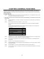
CHAPTER 6 GENERAL FUNCTIONS
The general functions determine the operations of the AD-4401 and are all stored in the EEPROM. Each function is
sorted into the groups by capabilities and represented by prefixing a function number (F-XX) with its group name. This
chapter describes how to set the general functions and their details. For functions related to options, see the descriptive
sections for the options.
SETTING METHOD
Step 1
•
With the [ENTER] key pressed and held, press the [SETPOINT] key. “Fnc” is displayed to inform you that
the indicator is entering the general function mode.
Note: When you did not want to enter the function mode, press the [ESC] key. The indicator will return to the
normal mode.
Step 2
Press the [ENTER] key. The indicator will switch to the general function mode and the cursor appears at
the letter, “c”.
Step 3
Select the target function group, using the [ ∧ ] , and [ ∨ ] keys
After selecting the function group, press the [ENTER] key. (In this example, select Basic Capabilities
Related)
The main display section displays the function number and the cursor appears in the lowest digit. The
Subdisplay section displays a set value for the function.
Group Name
Basic Capabilities Related
Weighing Sequence Related
Control I/O Input Related
Control I/O Output Related
Standard Serial Output Related
Parallel BCD Output Related
RS I/O Related
Setpoint Value input Related
Analog Output Related
Symbol
Fnc
Sq
in
out
si
bcd
rS
SP
An
Step 4
Using the [<], [>], [ ∧ ] , and [ ∨ ] keys, select the function number you want to set. In this example, select
FNCF-02. For your information, FNCF-02 is a capability of the [F] key.
Step 5
In this example, set the [F] key to a “print command.” Press the [ENTER] key. The Subdisplay section
starts blinking.
Step 6
Press the [ ∧ ] key. The Subdisplay section displays “1”.
Step 7
Press the [ENTER] key. The main display section starts blinking and you are returned to Step 4, selection
of the function number.
Step 8
Press the [ESC] key. The function number disappears and you are returned to Step 2.
Step 9
Press the [ESC] key again. The settings so far are saved in the EEPROM and the indicator is returned to
the normal mode.
25
6-1 BASIC CAPABILITIES RELATED
FNCF-
01
Name
Key switch
disable
Setting
Default
00000000
Parameter
00000000
to
11111111
0
1
2
02
Capabilities of
[F] Key
0
03
Display Rewrite
Rate
1
04
Display Content
of Subdisplay
Section
0
Description
3
4
5
6
7
8
1
2
3
0
1
2
3
4
5
6
0
Not disable
1
Disables
None
Print command for manual print
Hold
Hold function by the F key is not available if there
is any set to “HOLD” in the Control I/O (see6-3).
*Batch Start
*Emergency stop
Clear to zero
Clear tare
Clear accumulation
lb-kg conv. (USA ver.)
20 times/sec
10 times/sec
5 times/sec
None
Gross
Net
Tare
Final value (target weight)
Accumulated weight
Accumulated count
26
Each bit
corresponding
to the relevant
key.
This function is
only available in
the normal
mode.
All keys are
usable if keys
are enabled in
the Control I/O
(see6-3),
* Denotes
exclusive for
Built-in
automatic
program
mode.
Paste the
accessory label
to the front
panel in
compliance with
the display
content.
FNCF-
05
Name
“
“
Status display
Capability
Setting
Default
0
Parameter
0
Description
None
1
* discharging
2
Zero tracking
Value of each digit
and cutoff
frequency
"Discharging" is exclusively intended for
normal batching (built-in automatic
program mode).
0: None
1: 11.0Hz
2: 8.0Hz
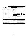
06
Digital Filter
(Series
connection of
two digital
filters.)
The digital filter is designed to suppress
dispersion of a load cell output signal.
Two of them are connected in series as
shown below.
3: 5.6Hz
48
00
to
79
4: 4.0Hz
5: 2.8Hz
6: 2.0Hz
7: 1.4Hz
Low frequency components, which cannot
be covered only by setting of the digital
filters, can be dealt with by equivalently
lowering the cutoff frequency of the digital
filters at FNCF-07.
8: 1.0Hz
9: 0.7Hz
07
Sampling
frequency
dividing ratio.
1
08
Hold operation
1
09
Comparison
stop at “hold”
0
1
to
10
1
2
Normal hold
Peak hold
During peak hold, the positive peak of the
weight value is held.
0
No
1
Yes
In Built-in automatic program mode, do not
set "1" because the weighing sequence
stops when comparison stops.
Lower the cutoff frequency of the digital filters equivalently by
reducing the specified sampling times to one.
27
6-2 WEIGHING SEQUENCE RELATED
SQF-
Name
Default
01
Selection of
comparison
weight
1
02
Automatic
accumulation
0
Internal count
2
Display count
0
No Automatic accumulation
Accumulates only acceptable
weight
Accumulates all values
No automatic free fall
compensation
Moving average of last four
times (See 7-9 for details.)
Fuzzy automatic free fall
compensation (See 7-10 for
details.)
Automatic free fall
compensation is made if a
loaded weight is within the final
+/- automatic free fall effective
width.
If Dribble Flow-time is shorter
than the setting, the preset
Free Fall is applied to the
weighing instead of the
Auto-Free-Fall compensation.
Real-time comparison
Synchronized with Batch Finish
Output
Not required
Required
1
2
0
03
Automatic free
fall
compensation
0
Setting
Description
Parameter
1
1
2
04
Automatic free
fall effective
width.
05
Unstable
Dribble Flow
Timer
06
Overlimit/underl
imit operation
2
07
Stability at
judgment
1
0
1
08
Maximum
number of
supplementary
flow times
0
0 to 255
0
0 to
99999999
3.0
0.0 to 25.5
(In step of
0.1 second)
1
2
0: Unused
Non-0: Set times
28
See 7-6 for details.
See 7-8 for details.
Only effective in Batch
weighing mode
Only effective in
Built-In-Automatic Program
mode.
Only effective in Batch
weighing mode.
Only effective in
Built-In-Automatic Program
mode.
SQF09
10
11
12
13
14
15
16
17
18
19
20
21
22
Name
Batch start wait
timer
Full-flow
comparator
Inhibiter timer
Medium-flow
comparator
Inhibiter timer
Dribble-flow
comparator
Inhibiter timer
Judgment wait
timer
Batch Finish
complete output
width
Batch
monitoring
timer
Supplementary
flow open timer
Supplementary
flow close timer
Discharging
start wait timer
Discharging
valve close wait
timer
Discharging
time monitor
timer
Add the final to
zero band
setting
Add the final to
full setting
Default
Setting
Description
Only effective in Built-In-Automatic
Program mode.
Parameter
0.0
Only normal batching(built-in automatic
program mode) is effective
0.0
Intentionally blank
0.0
0.0
0.0 to 25.5 (In
step of 0.1
second)
0.1
0: Until next Batch
start
0.0
Non-0: Set time
0
0.10
0 to 255 (In
step of 1
second)
0.01 to 2.55
(In step of
0.01 second)
0.1
0.0
0.0 to 25.5 (In
step of
0.1 second)
0: Unused
Non-0: Set time
(Intentionally
blank)
Only normal batching(built-in automatic
program mode) is effective
0.1
0
0
0 to 255 (In
step of
1 second)
0
1
0
Only effective in Built-In-Automatic
Program mode.
0
1
0: Unused
Non-0: Set time
Does not add the
final
Adds the final
Does not add the
final
Adds the final
29
Only loss-in-weight is effective
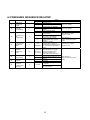
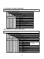
6-3 CONTROL I/O INPUT RELATED
INF-01 through INF-06 represents the input terminals A1 through A6, respectively. The content of setting is
common to each terminal, but initial setting differs.
INF-01: Capability of Input Terminal A1
INF-02 : Capability of Input Terminal A2
INF-03: Capability of Input Terminal A3
INF-04: Capability of Input Terminal A4
INF-05: Capability of Input Terminal A5
INF-06: Capability of Input Terminal A6
Setting
Default
Parameter
Description
0
No capability
1
Zero
2
Tare
3
Batch start
4
Emergency stop
5
Discharge start
6
Key enable
1
2
3
4
5
6
7
Automatic free fall command
8
Disable thumbwheel switch read
9
Clear tare
10
Accumulation command
11
Cancel previous accumulation
12
Clear accumulation
13
Hold
14
Print command for manual print
6-4 CONTROL I/O OUTPUT RELATED
OUT-01 through OUT-08 represent the output terminals B1 through B8, respectively. The content of setting is
common to each terminal, but initial setting differs.
OUTF-01: Capability of Output Terminal B1
OUTF-02: Capability of Output Terminal B2
OUTF-03: Capability of Output Terminal B3
OUTF-04: Capability of Output Terminal B4
OUTF-05: Capability of Output Terminal B5
OUTF-06: Capability of Output Terminal B6
OUTF-07: Capability of Output Terminal B7
OUTF-08: Capability of Output Terminal B8
Setting
Default
Parameter
Description
0
No capability
1
Zero range
2
Underlimit / (Hi-Hi)
3
Overlimit / (Hi)
[ ] Loss-in-weighing
4
Full flow / [Full] / (Go)
( ) Check-weighing
5
Medium flow / (Lo)
6
Dribble flow / (Lo-Lo)
7
Discharge gate open
1
2
3
4
5
6
7
8
8
Batch Finish
9
Stability
10
Online
11
Weighing sequence running
12
Weighing sequence error
13
Input acknowledge
14
Zero range error
15
Weighing capacity overflow
16
Low battery
30
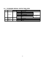
6-5
SIF-
01
STANDARD SERIAL OUTPUT RELATED
Name
Output Data
Setting
Default
1
Parameter
1
2
3
4
5
6
7
8
02
Data
transmitting
mode
1
03
Baud rate
2
1
2
3
1
2
Description
Displayed weight
Gross
Net
Tare
Gross/Net/Tare
Accumulated weight
Accumulated counts
Accumulated weight /Accumulated
counts
Stream mode
Auto-Print mode
Manual-Print mode
600 bps
2400 bps
31
A & D standard format
Accumulation data
format
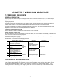
CHAPTER 7 WEIGHING SEQUENCE
7-1 WEIGHING SEQUENCE
GENERAL DESCRIPTION
Weighing sequence, means to output control signals to the units connected to the Control I/O, etc., by means of input
signals from the load cell and external unit. In order to cope with a wide range of applications, the AD-4401 has various
weighing sequences.
The weighing sequence differs depending on the weighing mode. The AD-4401 has 8 kinds of weighing modes; four
kinds of “batch weighing” for the hopper scale and other 4 kinds of “check weighing” for the platform scale.
The weighing modes can be sorted into “customer programmed control mode” and “built-in-automatic program mode”,
depending on their operations. The following describes their difference.
Customer programmed control mode
Always compares a weight to a setpoint and outputs its result to the Control I/O.
Built-in-automatic program mode
So that a hopper scale gate can be controlled by the AD-4401 alone, the control software conventionally contained in the
PLC is now incorporated in the weighing sequence.
Loading is initiated by a batch start signal from an external unit, and when the specified weight is obtained, a gate is
closed and a loading result is judged.
The AD-4401 can also deal with a discharging sequence.
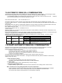
Weighing Mode CALF-14
Operation
Application
Normal batching
1
(Customer programmed
Customer
control mode)
Programmed Control
Loss-in-weight (Customer
mode (Real-time)
Batch
2
programmed control
Weighing
Hopper scale
mode)
Mode
Normal batching (Built-in
3
Built-in automatic
automatic program mode)
program mode
Loss-in-weight (Built-in
4
automatic program mode)
5
Check weighing 1
Check
Customer
6
Check weighing 2
Platform scale
Weighing
Programmed Control
7
Check weighing 3
Mode
mode (Real-time)
8
Check weighing 4
A sequence signal (comparison result) is output to the Control I/O. For the details of the Control I/O, see 8-1.
FUNCTIONING OF EACH WEIGHING MODE
The setpoints used in the weighing sequence are set with the keys, thumbwheel switches, and so on. The keys and
5-digit mode thumbwheel switch may be used in the same manner regardless of the weighing mode. When using the
16-digit mode thumbwheel switch, however, its digit distribution varies from one weighing mode to another. The
following describes the functioning of each weighing mode and connection of the 16-digit mode thumbwheel switch.
32
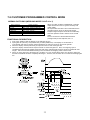
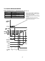
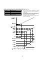
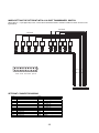
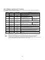
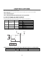
7-2 CUSTOMER PROGRAMMED CONTROL MODE
NORMAL BATCHING (WEIGHING MODE: CALF-14 = 1)
Output Terminal
Zero band
Full Flow
Medium Flow
Dribble Flow
Overlimit
Underlimit
When an output condition is established, a relevant
output terminal is turned on (power continuity with
output COM).
An output terminal number can be selected with the
general functions, OUTF-01 through OUTF-08.
A setpoint signal output is turned off unconditionally
when the operation mode is other than the normal
mode.
For the connection of the thumbwheel switch
(16-digit mode) for the setpoints, see 7-4.
Output Condition
Gross ≤ Zero band
Net ≥ Final - Optional preliminary
Net ≥ Final - Preliminary
Net ≥ Final - Free fall
Net > Final + Overlimit
Net < Final – Underlimit
FUNCTIONAL DESCRIPTION
1. First, press TARE to clear the display on the AD-4401 to zero.
2. Open gates G1 (full flow), G2 (medium flow), and G3 (dribble flow). The display on the AD-4401 is
incremented, and when it reaches optional preliminary its output is turned on and closes gate G1.
3. When the display reaches preliminary its output is turned on and closes gate G2.
4. When the display reaches final its output is turned on and closes gate G3. Now, one weighing cycle is
completed and the AD-4401 display shows the final value, indicating that hopper 2 has been loaded with that
weight. Use the overlimit/underlimit setting to check whether the weighing value is within limits.
5. When you open gate G4 to discharge into a container, you can use the setting of the zero range to make sure
that the raw material has been completely discharged. However, the AD-4401 cannot control the discharge gate
G4.
33
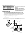
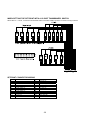
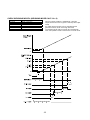
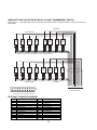
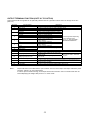
LOSS-IN-WEIGHT (WEIGHING MODE CALF-14 = 2)
Output Terminal
Zero band
Full (Hopper Full)
Medium Flow
Dribble Flow
Overlimit
Underlimit
Output Condition
Gross ≤ Zero band
Gross ≥ Full
-Net ≥ Final – Preliminary
-Net ≥ Final – Free fall
-Net > Final + Overlimit
-Net < Final – Underlimit
When an output condition is established, a relevant
output terminal is turned on (power continuity with
output COM).
An output terminal number can be selected with the
general functions, OUTF-01 through OUTF-08.
A setpoint signal output is turned off unconditionally
when the operation mode is other than the normal
mode.
For the connection of the thumbwheel switch
(16-digit mode) for the setpoints, see 7-4.
FUNCTIONAL DESCRIPTION
1. Initially, with the weighing hopper 2 being empty, the AD-4401 displays the zero range at the gross.
2. In this state, open gate G1. When the display on the AD-4401 reaches the Full (optional preliminary) set value,
its output is turned on and closes gate G1. The weighing hopper 2 has now been filled with raw material.
3. Press TARE. The display on the AD-4401 is cleared to 0.
4. Open gates G2 and G3. The display of the AD-4401 is decremented, and when it reaches preliminary
Its output is turned on and closes gate G2.
5. When the display reaches final output is turned on and closes gate G3.
Now, one weighing cycle has completed and the display on the AD-4401 shows the final value, indicating that
receiving bin has been loaded with that weight. Use the setting of overlimit/underlimit to check whether the
weighing value is within limits.
5. When the volume of material left in the weighing Hopper 2 becomes less than Zero band, Zero band
Output signal is turned on.
Note: SQF-21/ SQF-22 setting enables to add automatically FINAL to ZERO BAND or FULL. Therefore there is
always enough ingredient left in the hopper for a measurement.
34
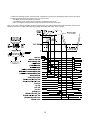
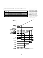
7-3 BUILT-IN AUTOMATIC PROGRAM MODE
NORMAL BATCHING / NO SUPPLEMENTARY FLOW
(WEIGHING MODE CALF-14 = 3)
Output Terminal
Zero band
Full Flow
Medium flow
Dribble flow
Overlimit
Underlimit
When an output condition is established, full flow,
medium flow, and dribble flow outputs are turned
off, but the other outputs are turned on.
Once the full flow, medium flow, and dribble flow
are turned off, they are not turned on until the next
start of loading.
Overlimit/underlimit is activated based on the net
upon batch finish. (May be changed to real-time
operation)
The zero range is a customer programmed control
mode operation.
For the connection of the thumbwheel switch
(16-digit mode) for setpoints, see 7-4.
Output Condition
Gross ≤ Zero band
Net ≥ Final - Optional preliminary
Net ≥ Final - Preliminary
Net ≥ Final – Free Fall
Net > Final + Overlimit
Net < Final-Underlimit
FUNCTIONAL DESCRIPTION
1. The instrument is waiting for a batch start signal or
discharging start signal to be input.
2. When the batch start signal is input, the Batch Start wait timer starts.
3. When the Batch Start wait timer completes the set time;
• Full-flow, medium-flow, and dribble-flow output signals are turned on.
• The full-flow comparator inhibitor timer starts.
• The Batch monitoring timer starts.
4. When the weight reaches optional preliminary setting:
• The full-flow output is turned off.
• The medium-flow comparator inhibitor timer starts.
5. When the weight reaches preliminary' setting:
• The medium-flow output is turned off.
• The dribble-flow comparator inhibitor timer starts.
6. When the weight reaches free fall setting:
•The dribble-flow output is turned off.
• The judgment wait timer starts.
7. When the weight has stabilized after the judgment wait timer completes the set time;
• If automatic free fall compensation is being used, its calculation will be made.
• The Batch Finish output signal is turned on.
• If there is excess or shortage, a judgment result output signal (overlimit or underlimit) will be turned on.
• The Batch monitoring timer is reset.
• The net is accumulated automatically.
• The data is output from the interface set for auto print.
8. If the discharging start signal is input, the discharging start wait timer will start.
9. When the discharging start wait timer completes the set time;
• The discharging output signal is turned on.
• The discharging time monitor timer starts.
10. When the gross becomes lower than the zero range;
• The discharging valve close wait timer starts.
• The discharging time monitor timer is reset.
35
11. When the discharging valve close wait timer completes the set time, the discharging output signal is turned off.
12. When the Batch Start input signal for the next cycle is input;
• The Batch Finish output signal is turned off.
• The judgment result output signal (overlimit or underlimit) is turned off.
• Now, the weighing sequence has cycled and restarts from Step 2 at this time.
Note: In the case of built-in-automatic program mode batching, the setpoint data is held until batch finish since start of
batching. Therefore, a setpoint altered during loading takes effect after batch finish is output.
36
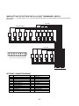
NORMAL BATCHING/ WITH SUPPLEMENTARY FLOW
(WEIGHING MODE CALF-14 = 3)
Supplementary flow automatically turns on the dribble flow for the specified time when the loaded weight is not sufficient.
To make supplementary flow, set the “maximum supplementary flow times, SQF-07,” to other than 0, and the
“supplementary flow open timer, SQF-15,” and “supplementary flow close timer, SQF-16,” to their respective times.
Supplementary flow is also available in loss-in-weight (built-in automatic program mode).
FUNCTIONAL DESCRIPTION
1. The instrument is waiting for the Batch Start signal or discharging start signal to be input.
2. When the external Batch Start signal is input, the Batch Start wait timer starts.
3. When the Batch Start wait timer completes the set time;
• Full-flow, medium-flow, and dribble-flow output signals are turned on.
• The full-flow setpoint disable, and the Batch monitoring timers start.
4. When the weight reaches optional preliminary setting:
• The full-flow output is turned off.
• The medium-flow comparator inhibitor timer starts.
5. When the weight reaches preliminary setting:
• The medium-flow output is turned off.
• The dribble-flow comparator inhibitor timer starts.
6. When the weight reaches free fall setting:
• The dribble-flow output is turned off.
• The judgment wait timer starts.
• The Batch monitoring timer is reset.
7. When the weight has stabilized after the judgment wait timer completes the set time;
• If automatic free fall compensation is being used, its calculation will be made.
If the net is insufficient;
• The dribble-flow output signal is turned on.
• The supplementary flow open timer starts.
8. When the supplementary flow open timer completes the set time;
• The dribble-flow output signal is turned off.
• The supplementary flow close timer starts.
9. When the supplementary flow close timer completes the set time;
• It is checked whether the net is insufficient, and if yes;
• The dribble-flow output signal is turned on.
• The supplementary flow open timer starts.
10. When the supplementary flow open timer completes the set time;
• The dribble-flow output signal is turned off.
• The supplementary flow close timer starts.
11. When the supplementary flow close timer completes the set time;
• It is checked whether the net is insufficient, and if not;
• The Batch Finish output signal is turned on.
• If a judgment result is overlimit, an overlimit output is turned on.
• The Batch monitoring timer is reset.
• The net is accumulated automatically.
• The data is output from the interface set for auto print.
12. If the discharging start input signal is turned on, the discharging start wait timer will start.
37
13. When the discharging start wait timer completes the set time;
• The discharging output signal is turned on, and the discharging time monitor timer starts.
14. When the gross becomes lower than the zero range;
• The discharging valve close wait timer starts.
• The discharging time monitor timer is reset.
15. When the discharging valve close wait timer completes the set time, the discharging output signal is turned off.
16. When the Batch Start signal for the next cycle is input;
• The Batch Finish output signal is turned off.
• The judgment result output signal (overlimit or underlimit) is turned off.
• Now, the weighing sequence has cycled and restarts from Step 2 at the same time.
38
LOSS-IN-WEIGHT (WEIGHING MODE CALF-14 = 4)
Output Terminal
Zero band
Full (Hopper full)
Medium flow
Dribble flow
Overlimit
Underlimit
Output Condition
Gross ≤ Zero band
Gross ≥ Final - Full
- Net ≥ Final - Preliminary
- Net ≥ Final – Free Fall
- Net > Final + Overlimit
- Net < Final-Underlimit
When an output condition is established, medium
flow and dribble flow outputs are turned off, but the
other outputs are turned on.
Once the medium flow and dribble flow are turned
off, they are not turned on again until the next start of
loading.
The overlimit/underlimit is activated based on the net
upon batch finish. (Can be changed to Real-time
mode operation)
The zero range is a customer programmed control
mode operation.
For the connection of a thumbwheel switch (16-digit
mode) for setpoints, see 7-4.
FUNCTIONAL DESCRIPTION
1. If the zero range signal is being output, replenish the raw material until a full signal is output.
2. Wait for stabilization and input a tare subtraction signal.
3. If a Batch Start signal is input, the Batch Start wait timer starts.
4. When the Batch Start wait timer completes the set time;
• The medium and dribble-flow output signals are turned on.
• The medium-flow comparator inhibitor timer starts.
• The Batch monitoring timer starts.
5. When the weight reaches preliminary setting:
• The medium-flow output is turned off.
• The dribble-flow comparator inhibitor timer starts.
6. When the weight reaches preliminary free fall setting:
• The dribble-flow output is turned off.
• The judgment wait timer starts.
7. When the weight has stabilized after the judgment wait timer completes the set time;
• If automatic free fall compensation is being used, its calculation will be made.
• The Batch Finish output signal is turned on.
• If there is an excess or shortage, the judgment result output signal (overlimit or underlimit) is turned on.
• The Batch monitoring timer is reset.
• The net is accumulated automatically.
• The data is output from the interface set for auto print.
Note:
SQF-21 and SQF-22 settings enable to add automatically FINAL to ZERO BAND or FULL. Therefore there is always
enough ingredient left in the hopper for a measurement.
• In the case of built-in-automatic program mode batching, the setpoint data is held until batch finish since start of loading.
Therefore, a setpoint altered during loading takes effect after batch finish is output.
39
40
SUPPLEMENTARY DESCRIPTION FOR BUILT-IN-AUTOMATIC PROGRAM MODE
To subtract the tare automatically prior to loading
Set the Batch Start wait timer to 0.1 second or more and connect the tare subtraction input and the Batch Start
input in parallel.
When using with a high-speed packer and it is difficult to stabilize after the judgment wait timer completes the set
time
Set stability at Judgment to “Unrequired.”
When the Batch Start signal is input while outputting the weighing completion signal
The Batch Start input is accepted and the weighing completion output is turned off.
To discharge prior to starting loading
Input the discharging start signal before the Batch Start signal. Begin with the discharging sequence.
When an emergency stop signal is input
Since the instrument waits for the Batch Start signal to be input, regardless of the running condition, all the
loading signals and discharging signals are turned off. Also, a weighing sequence error signal is output. This
signal is output continuously until the loading or discharging start signal is input.
When loading has taken more than the specified time, an alarm signal is output as follows
With the Batch monitoring timer, set the maximum expected loading time. If loading exceeds this time, each
loading signal will be turned off and a weighing sequence error signal will be output. Input the Batch Start signal
to reload, and input the discharging start signal to discharge.
Functioning of the comparator inhibitor timer
In order to prevent the medium-flow or dibble-flow gate from being closed by mistake due to fluctuations of the
weight value resulting from vibration upon closing the full-flow gate, the weight value is not compared for the set
time of the comparator inhibitor timer when the loading signal is changed.
Functioning of the medium flow when preliminary is set to 0
No medium flow is provided when preliminary is set to 0. Likewise, no full flow is provided when optional
preliminary is set to 0. When free fall is set to 0, however, dribble flow is provided until the net exceeds the final.
Functioning of the medium flow and dribble flow when preliminary is set smaller than free fall
When the dribble flow is turned off, the medium flow is also forced to OFF.
Set Optional preliminary > Preliminary > Free Fall. (0 is allowed because of A8)
41
7-4 SUPPLEMENTARY DESCRIPTION FOR BATCH WEIGHING
When setting the setpoint with the 16-digit thumbwheel switch
In batch batching, connection of the 16-digit thumbwheel switch is common.
When SPF-01 = 2 is set, connect the thumbwheel switch to the SET POINT connector as show in the figure below.
SETPOINT CONNECTOR WIRING
Pin #
A1
A2
A3
A4
A5
A6
A7
A8
A9
A10
A11
A12
1
2
4
8
Final 100
Final 101
Final 102
Final 103
Final 104
Free Fall 100
Free Fall 101
Free Fall 102
Pin #
B1
B2
B3
B4
B5
B6
B7
B8
B9
B10
B11
B12
Prelim. 100
Prelim. 101
Prelim. 102
Prelim. 103
OVER 100
OVER 101
UNDER 100
UNDER 101
Used internally
Shield
42
7-5 CHECK WEIGHING MODE
CHECK WEIGHING MODE 1 (WEIGHING MODE CALF-14 = 5)
Output Terminal
Zero band
Hi-Hi
Hi
Go
Lo
Lo-Lo
Output Condition
Gross ≤ Zero band
Net > Hi-Hi limit
Net > Target Weight + Hi limit
Target Weight + Hi limit ≥ Net ≥ Target
Weight – Lo limit
Net < Target Weight – Lo limit
Net < Lo-Lo limit
When an output condition is established, a
relevant output terminal is turned on (power
continuity with output COM).
An output terminal number can be selected
with the general functions, OUTF-01 through
OUTF-08.
The setpoint signal output is turned off
unconditionally when the operation mode is
other than the normal mode.
43
WHEN SETTING THE SETPOINT WITH A 15-DIGIT THUMBWHEEL SWITCH
When SPF-01 = 2 is set, connect the thumbwheel switch to the SET POINT connector as show in the figure below.
SETPOINT CONNECTOR WIRING
Pin #
A1
A2
A3
A4
A5
A6
A7
A8
A9
A10
A11
A12
1
2
4
8
Target weight 100
Target weight 101
Target weight 102
Target weight 103
Target weight 104
Hi Limit 100
Hi Limit 101
Hi Limit 102
Pin #
B1
B2
B3
B4
B5
B6
B7
B8
B9
B10
B11
B12
Hi Limit. 103
Hi Limit. 104
Lo Limit 100
Lo Limit 101
Lo Limit 102
Lo Limit 103
Lo Limit 104
Used internally
Shield
44
CHECK WEIGHING MODE 2 (WEIGHING MODE CALF-14 =
6)
Output
Terminal
Zero band
Hi-Hi
Hi
Go
Lo
Lo-Lo
Output Condition
Gross ≤ Zero band
Net > Hi-Hi Limit
Target Weight + Hi-Hi Limit ≥ Net > Target Weight
Target Weight + Hi Limit ≥ Net ≥ Target Weight – Lo Limit
Target Weight – Lo-Lo Limit ≤ Net < Target Weight – Lo Limit
Net < Lo-Lo Limit
45
When an output condition is
established, a relevant output
terminal is turned on (power
continuity with output COM).
An output terminal number can
be selected with the general
functions, OUTF-01 through
OUTF-08.
The setpoint signal output is
turned off unconditionally when
the operation mode is other
than the normal mode.
WHEN SETTING THE SETPOINT WITH A 15-DIGIT THUMBWHEEL SWITCH
When SPF-01 = 2 ( 16-digit mode ) is set, connect the thumbwheel switch to the SET POINT connector as show in the
figure below.
;I <IKIQ
?AOGEQ REIGHQ
9
9
9
9
9
9
.-1
.-0
.-/
.-.
.--
51/.
51/.
51/.
51/.
51/.
9
9
.-1 .-0
51/.
51/.
9
9
.-/ .-. .-51/.
51/.
51/.
: I M D E + ?M P H I B A . > . 2 5 5 M O Q H E C M K N A Q I B J E ,
<M <IKIQ
8
7
.
/
0
1 2
3
4
5
6
.- .. ./
@IER FOMK QHE =EAO NALEJ
9
9
9
9
9
.-1
.-0
.-/
.-.
.--
51/.
51/.
51/.
51/.
51/.
. 0 2 4 6 .. . 0 2 4
/ 1 3 5 .- ./ / 1 3 ./
7
SETPOINT CONNECTOR WIRING
Pin #
A1
A2
A3
A4
A5
A6
A7
A8
A9
A10
A11
A12
1
2
4
8
Target weight 100
Target weight 101
Target weight 102
Target weight 103
Target weight 104
Hi Limit 100
Hi Limit 101
Hi Limit 102
Pin #
B1
B2
B3
B4
B5
B6
B7
B8
B9
B10
B11
B12
Hi Limit. 103
Hi Limit. 104
Lo Limit 100
Lo Limit 101
Lo Limit 102
Lo Limit 103
Lo Limit 104
Used internally
Shield
46
8
CHECK WEIGHING MODE 3 (WEIGHING MODE CALF-14 = 7)
Output Terminal
Zero band
Hi-Hi
Hi
Go
Lo
Lo-Lo
Output Condition
Gross ≤ Zero band
Net > Hi-Hi Limit
Net > Hi Limit
Hi Limit ≥ Net ≥ Lo Limit
Net < Lo Limit
Net < Lo-Lo Limit
When an output condition is established, a relevant
output terminal is turned on (power continuity with
output COM).
An output terminal number can be selected with the
general functions, OUTF-01 through OUTF-08.
The setpoint signal output is turned off
unconditionally when the operation mode is other
than the normal mode.
47
WHEN SETTING THE SETPOINT WITH A 10-DIGIT THUMBWHEEL SWITCH
When SPF-01 = 2 (16-digit mode) is set, connect the thumbwheel switch to the SET POINT connector as show in the
figure below.
<L <HJHP
;H <HJHP
9
9
9
9
9
.-1
.-0
.-/
.-.
.--
51/.
51/.
51/.
51/.
51/.
9
9
.-1 .-0
51/.
51/.
9
9
9
.-/ .-. .-51/.
51/.
51/.
: H L D E + ?L O G H B A . > . 2 5 5 L N P G E C L J M A P H B I E ,
8
7
.
/
0
1 2
3
4
5
6
.- .. ./
@HEQ FNLJ PGE =EAN MAKEI
. 0 2 4 6 .. . 0 2 4
/ 1 3 5 .- ./ / 1 3 ./
7
SETPOINT CONNECTOR WIRING
Pin #
A1
A2
A3
A4
A5
A6
A7
A8
A9
A10
A11
A12
1
2
4
8
Hi Limit 100
Hi Limit 101
Hi Limit 102
Pin #
B1
B2
B3
B4
B5
B6
B7
B8
B9
B10
B11
B12
Hi Limit. 103
Hi Limit. 104
Lo Limit 100
Lo Limit 101
Lo Limit 102
Lo Limit 103
Lo Limit 104
Used internally
Shield
48
8
CHECK WEIGHING MODE 4 (WEIGHING MODE CALF-14 = 8)
Output Terminal
Zero band
Hi-Hi
Hi
Go
Lo
Lo-Lo
Output Condition
Gross ≤ Zero band
Net > Hi-Hi Limit
Hi Limit > Net ≥ Hi Limit
Hi Limit ≥ Net ≥ Lo Limit
Lo Limit > Net ≥ Lo-Lo Limit
Net < Lo-Lo Limit
When an output condition is established, a relevant
output terminal is turned on (power continuity with output
COM).
An output terminal number can be selected with the
general functions, OUTF-01 through OUTF-08.
The setpoint signal output is turned off unconditionally
when the operation mode is other than the normal mode.
49
WHEN SETTING THE SETPOINT WITH A 16-DIGIT THUMBWHEEL SWITCH
When SPF-01 = 2 (16-digit mode) is set, connect the thumbwheel switch to the SET POINT connector as show in the
figure below.
=N ?NPNV
=N -=N ?NPNV
:
:
:
:
:
:
:
:
/.1
/.0
/./
/..
/.1
/.0
/./
/..
620/
620/
620/
620/
620/
620/
620/
620/
; N R J K + ER U M N H G / D / 3 6 6 R T V M K I R P S G V N H O K ,
:
:
:
:
:
:
:
:
/.1
/.0
/./
/..
/.1
/.0
/./
/..
620/
620/
620/
620/
620/
620/
620/
620/
?R ?NPNV
?R-?R ?NPNV
/ 1 3 5 7 // / 1 3 5 /0
0 2 4 6 /. /0 0 2 4 6
9
8
/
0
1
2 3
4
5
6
7
8
/. // /0
FNKW LTRP VMK CKGT SGQKO
SETPOINT CONNECTOR WIRING
Pin #
A1
A2
A3
A4
A5
A6
A7
A8
A9
A10
A11
A12
1
2
4
8
Hi-Hi Limit 100
Hi-Hi Limit 101
Hi-Hi Limit 102
Hi-Hi Limit 103
Hi Limit 100
Hi Limit 101
Hi Limit 102
Hi Limit 103
9
ER D < E B A > @ E
Pin #
B1
B2
B3
B4
B5
B6
B7
B8
B9
B10
B11
B12
Lo Limit 100
Lo Limit 101
Lo Limit 102
Lo Limit 103
Lo-Lo Limit 100
Lo-Lo Limit 101
Lo-Lo Limit 102
Lo-Lo Limit 103
Used internally
Shield
50
7-6 COMPARISON WEIGHT
Although the weight compared with the setpoint is mainly the net, the gross is partially compared. Since the net
assumes a negative value in loss-in-weight, setpoint is made with the polarity reversed.
Setpoint of the weight with the setpoint allows you to select the display count and internal count.
One graduation of the weight value appearing in the display section is the minimum graduation set with CALF-03.
Provided internally is the weight value called high-resolution “internal count” with the minimum graduation calculated as 1.
For example, when the minimum graduation is 10, a display changes only in a step of 10, but a finer change is captured
internally.
Batch weighing mode mainly uses the internal count, and Check comparison mode uses the display count.
This is because the internal count is superior from a viewpoint of weighing accuracy, but if the platform scale is compared
using the internal count, it appears as if the displayed weight and comparison result are contradictory to each other.
The comparison weight is selected with the general function, “Selection of Setpoint Weight SQF-01.” It is meaningless to
use the internal count, unless the minimum graduation is 2 or more.
7-7 AUTO PRINT
Auto print is the capability to output the Batch Finish weight from the external output where the output mode has been set
to Auto Print. The output timing is as follows depending on the weighing mode.
CUSTOMER PROGRAMMED CONTROL MODE (NORMAL BATCHING , LOSS-IN-WEIGHT)
Since the weighing completion timing is not definite in customer programmed control mode, the weight is output only
once when a setpoint target net value is stabilized at 5D or greater.
To output again, the setpoint target net value must be to less than 5D (5 graduations).
BUILT-IN-AUTOMATIC PROGRAM MODE
The weight is output the moment the weighing sequence encounters the batch finish timing.
7-8 AUTOMATIC ACCUMULATION
The Automatic accumulation function automatically accumulates the net weight after weighing. The its timing is the same
as auto print, but its functioning differs depending on “Automatic accumulation SQF-02.”
SQF-
Name
Default
02
Automatic
accumulation
0
Parameter
0
1
2
Setting
Description
No Automatic accumulation
Accumulates only acceptable weight
Accumulates all values
51
7-9 AUTOMATIC FREE FALL COMPENSATION
Automatic free fall compensation is the capability to reduce a loading error in batch weighing. The following two kinds
can be selected depending on the functioning of the automatic free fall compensation (SQF-03).
1) Automatically setting the “moving average of the last four actual free falls” as the free fall for the next
weighing.
2) Automatically adjusting free fall setting, applying fuzzy logic.
This section describes item 1; item 2 is described in 7-10.
The hopper scale has a certain increase in the weight value until batch finish since the dribble gate is closed. This
increase is called a free fall. To perform weighing with little error, the free fall setting for the setpoint must be equal to an
actual free fall.
As a remedy, there is an option to automatically update the “moving average of the last four actual free falls” as the next
free fall setting. The loading error and actual free fall are expressed by the following formulas.
Error = Batch Finish net - final
Actual free fall = Batch Finish net - *Dribble flow cut net
* Final - Free fall
When the loading error exceeds the automatic free fall effective width (SQF-04), automatic free fall compensation is not
performed, taking it as an error.
Since customer programmed control mode judges the Batch Finish timing externally, a calculation is made assuming that
weighing is completed when an automatic free fall command is input to the Control I/O.
Automatic free fall compensation is designed to reduce the weighing error in batch weighing. Therefore, Check
Weighing does not have this capability.
SQF03
04
Name
Automatic Free
Fall
Compensation
Automatic Free
Fall Effective
Width
Default
0
0
Parameter
0
1
2
0
to
9999999
Setting
Description
No Automatic Free Fall Compensation
Moving average of last four actual Free Falls
Fuzzy Automatic Free Fall Compensation
If a loading weight is within the final +/- automatic
Free Fall effective width, Automatic Free Fall
Compensation is on.
7-10 FUZZY AUTOMATIC FREE FALL COMPENSATION
Automatic free fall compensation mentioned above is very effective when the actual free fall does not change.
However, it is very difficult for conventional automatic free fall compensation to eliminate the
following actual free fall fluctuation factors.
• Changes of specific gravity or viscosity of the weighed substance
• Inconstant flow rate due to a change of water pressure, and so on
• Bad flow due to adherence of the weighed substance to the surface of the hopper
• Clumps in the weighed substance
Fluctuation factors mentioned above affect the actual free fall, but their relations are fuzzy.
The AD-4401 takes in their effects as the data 1 through 3 and reflects the fuzzy data in calculation of the free fall,
applying fuzzy logic theory.
1) Flow rate and its change
• The actual free fall increases as the flow rate becomes greater.
• Reliability of the actual free fall becomes higher as a flow is stabilized.
2) Lapse of time
• The newest weighing result is least affected by a secular change.
3) Reliability of the loading result
• Higher reliability is given to the actual free fall where distribution of the loading result is more focused.
Note : Precautions for using Fuzzy Automatic Free Fall Compensation
• Fuzzy automatic free fall compensation is not made on the first loading after free fall setting for a setpoint.
• Take 3 seconds or more to carry out the dribble flow in order to calculate an internal flow rate.
• The free fall value always changes because it is calculated per sampling.
52
CHAPTER 8 INTERFACE
8-1 CONTROL I/O
The Control I/O is intended for inputting/outputting weighing control signals to an external unit. It consists of 6 inputs and
8 outputs.
The capability of each input/output terminal can be selected, except COM (see 6-3, 6-4 for selection method).
Upon shipment, the Control I/O terminals were set for normal batching (Built-in Automatic Program Mode).
TERMINAL FUNCTIONS IN THE BUILT-IN AUTOMATIC PROGRAM MODE
Division
Input
COM
Output
Terminal
No.
Function Name
Description
A1
Zero
A2
A3
Tare
Batch start
A4
Emergency stop
A5
Discharge start
A6
Key enable
A7
A8
B1
B2
B3
B4
B5
B6
B7
B8
Input COM
Output COM
Zero band
Underlimit
Overlimit
Full flow
Medium flow
Dribble flow
Discharge
Batch finish
Clears the gross to zero. However, it does not function beyond the
range set with the calibration
Subtracting the tare weight and a displayed weight becomes the net.
Starts the weighing sequence.
Stops charging or discharging and turns on the output terminal set for
the weighing sequence error.
Starts the discharging sequence.
While this input is ON, the keys disabled by the general function
(FNC-01) are enabled.
Input COM. Each input is accepted by shorting it with this terminal.
Output COM
Turned on when the gross is lower than zero band setting.
Turned on when the judgment result is underlimit.
Turned on when the judgment result is overlimit.
Turned on when the weighing sequence is full flow.
Turned on when the weighing sequence is medium flow.
Turned on when the weighing sequence is dribble flow.
Turned on during the discharging sequence.
Turned on when the weighing sequence is completed and judged.
CONTROL I/O CONNECTOR, ACCESSORY
Parts Name
Connector
Connector cover
Q'ty
1
1
A&D’s parts Number
JI-361J016-AG
JI-360C016-B
53
Description
FCN361J016-AU (or AG),Fujitsu
FCN360C016-B, Fujitsu
INPUT TERMINAL FUNCTION (INF-01 TO INF-06)
The capabilities of the input terminals A1 through A6 can be optionally selected with the “general functions INF-01
through INF-06.” (See 6-3 for method of selection)
Set value
0
Terminal No.
<No function>
Function Name
N/A
1
Zero
Edge
2
3
Tare
Batch start
Edge
Edge
4
Emergency
stop
Level
5
Discharge start
Edge
6
Key enable
Level
7
Automatic free
fall command
Edge
8
9
10
11
12
13
14
Note 1:
Note 2:
Note 3:
Digital switch
read disable
Clear tare
Accumulation
command
Accumulation
cancel
Clear
accumulation
Hold
Print command
for manual print
Description
N/A
Clears the gross to zero. However, it does not function beyond the
condition set with the calibration.
Subtracts the tare. A displayed weight becomes the net.
Starts the batch weighing.
For the Built-in
Stops batching or discharging and
automatic program
turns on an output pin set for the
mode.
weighing sequence error.
For Normal batching in
Starts the discharging sequence.
the Built-in automatic
Exclusive for sequential batching
program mode
While this input is turned on, the keys disabled by the general
function(FNC-01) are enabled.
Normal batching &
Performs automatic free fall
Loss-in weighing in the
compensation. Exclusive for customer
Customer programmed
programmed control mode
control mode
Level
While this input is turned on, reading of the digital switch stops.
Edge
Clears the tare value. A displayed value becomes the gross.
Accumulates the current net into the accumulated weight and
increments the accumulated times by one.
Edge
Edge
Subtracts the previously accumulated weight from the
accumulated weight and decrements the accumulate.
Edge
Clears the accumulated weight and accumulated times.
Level
While this input is turned on, the weight value is held.
Outputs the specified data from the external input/output set for
manual print.
Edge
An edge input is accepted when it is switched from OFF to ON, and a level input is accepted while it is
ON.
Input ON refers to the state when each input terminal and input COM are connected together.
An input has chattering eliminated. Both ON time and OFF time require 50 ms or more.
In order to prevent malfunctioning, each input terminal does not accept an input in the non-normal mode
such as “before displaying the weight after power-on” or “OFF mode.”
54
OUTPUT TERMINAL FUNCTION (OUTF-01 TO OUTF-08)
Output terminals B1 through B6 can be optionally selected with the “general functions OUTF-01 through OUTF-08.”
(See 6-4.)
Set value
0
1
2
3
4
5
Function Name
No function
Zero range
Underlimit
Hi-Hi
Overlimit
Hi
Full flow
Full
Go
Medium flow
Lo
6
Dribble flow
7
8
9
10
Lo-Lo
Discharge
Batch finish
Motion detection
Online
11
Weighing sequence running
12
Weighing sequence error
13
Input acknowledge
14
Zero error
15
16
Capacity overflow
Low battery
Note 1:
Description
N/A
Turned on when the gross is close to the zero range.
In case of Normal batching/Loss-in-weight
In case of check weighing
In case of Normal batching/Loss-in-weight
In case of check weighing
In case of normal batching
In case of Loss-in-weight
Functioning differs depending
In case of check weighing
on the weighing mode
In case of Normal batching /
CALF-14. See CHAPTER 7
Loss-in-weight
WEIGHING SEQUENCE.
In case of check weighing
In case of Normal batching /
Loss-in-weight
In case of check weighing
Exclusive for built-in automatic program
Turned on when the weight value is stabilized.
Turned on in case of the normal mode
Turned on when waiting for an input of the
Exclusive for built-in automatic
loading signal.
program
Turned on when a weighing sequence
error occurs.
Turned on for 0.5 second after detecting a rise edge of the input terminal.
Turned on when zeroing was performed and could not be accepted because it
was beyond the condition.
Turned on when the gross overflows.
Turned on when the memory backup battery has run out.
Output ON refers to the state that the open collector circuit for each output and output COM have power
continuity. (See 8-1 for circuit description)
In order to prevent malfunctioning, each output terminal is turned off in the non-normal mode such as
“before displaying the weight after power-on” or “OFF mode.”
55
8-2 SETPOINT
The setpoint refers to a weight setting such as the reference value and final required for the weighing sequence.
Connect the thumbwheel switch which makes this setting to the SET POINT connector.
Connection of the setpoint differs depending on the general function, “Setpoint Read Mode (SPF-01).” It also differs
depending on the weighing mode.
THUMBWHEEL SWITCH NOT REQUIRED MODES; SPF-01 = 1
You do not have to connect anything to the SET POINT connector. (Setting upon shipment)
5-DIGIT MODE; SPF-01 = 1
When the minimum graduation is set to 10 or more, the value of the thumbwheel switch is input and multiplied by 10.
Pin #
A1
1
A2
2
A3
4
A4
8
A5
Final 100
A6
Final 101
A7
Final 102
A8
Final 103
A9
Final 104
B12
Shield
Only use the pins listed
above.
When the minimum
graduation is set to 10 or
more, the value of the
thumbwheel switch is input
and multiplied by 10.
CONNECTOR FOR SETPOINT (NOT INCLUDED WITH THE ACCESSORIES.)
Parts Name
Connector
Connector cover
Q'ty
1
1
A&D’s parts Number
JI-361J024-AG
JI-360C024-B
Description
FCN361J024-AU(or AG), Fujitsu
FCN360C024-B, Fujitsu
16-DIGIT MODE; SPF-01 = 2
Depends on the weighing mode. See {CHAPTER 7. WEIGHING SEQUENCE}
When the minimum graduation is set to 10 or more, the value of the thumbwheel switch is input and multiplied by 10.
56
8-3 STANDARD SERIAL OUTPUT (SER. OUT)
The standard serial output is a 20 mA current loop. It is located on the rear panel of the indicator, and is used to connect
a remote indicator or printer. This output does not have a power supply. Therefore, the external unit must supply the
power.
Setting of the standard serial output is done with the general functions, SIF-01 through SIF-03.
CONNECTOR FOR STANDARD SERIAL OUTPUT (INCLUDED WITH THE ACCESSORIES.)
Parts Name
Q'ty
1
Connector
SIF-
01
Name
Output data
Default
1
A&D’s parts Number
JA-TCP0576
Parameter
1
2
3
4
5
6
7
8
02
Data
transfer
mode
1
03
Baud rate
2
1
2
3
1
2
Description
TCP0576, Hoshi Electric
Setting
Description
Displayed weight
Gross
Net
Tare
Gross/Net/Tare
Accumulated weight
Accumulated counts
Accumulated weight/
counts
Stream
Auto print
Manual print
600 bps
2400 bps
A&D standard format
Accumulated
Accumulated data
format
INTERFACE SPECIFICATION
Signal System
Data bit
Parity bit
Stop bit
Code used
20 mA current loop 1=20 mA, 0=0
mA
7 bits
1 bit (EVEN)
1 bit
ASCII
57
Note: When connecting any unit other
than an external indicator or printer
manufactured by A & D, the device
must supply power (active current loop)
or an external power supply must be
used.
OUTPUT DATA
There are two kinds of transmission formats; “A & D standard format” and “Accumulation data format”.
The A & D standard format has been used for our weighing indicators. It consists of two headers, data, unit, and
terminator. The Accumulation data format outputs a simple header, numerical data, unit and terminator. The following
shows their examples.
<A & D STANDARD FORMAT>
Header 1
S
T
Header2
G
S
,
Data (Eight digits; polarity and decimal point included)
+
0
0
1
2
3
4
5
,
ASCII code
ST
US
OL
GS
NT
TR
,
0 to 9
+
SP (space)
•
SP SP
SP g
kg
SP t
lb
Header-1
Header-2
Separator
Data (ASCII code)
Unit
Hexadecimal number
[53 54]
[55 53]
[4F 4C]
[47 53]
[4E 54]
[54 52]
[2C]
[30 to 39]
[2B]
[2D]
[20]
[2E]
[20 20]
[20 67]
[6B 67]
[20 74]
[6C 62]
Unit
k
g
Terminators
CR
LF
Description
(STable)
(UnStable)
(Over Load)
(GroSs)
(NeT)
(TaRe)
(No unit)
(g)
(kg)
(t)
(lb)
< Example >
8 Digits Including Data, Polarity, and
Decimal Point
Header
2
Header
1
Unit
Terminator
Gross
S
T
,
G
S
,
+
0
0
1
2
3
4
5
k
g
CR
LF
Net
S
T
,
N
T
,
+
0
0
1
0
0
0
0
k
g
CR
LF
Tare
S
T
,
T
R
,
+
0
0
0
2
3
4
5
k
g
CR
LF
S
T
,
G
S
,
+
0
1
2
3
.
4
5
k
g
CR
LF
O
L
,
G
S
,
+
SP
SP
SP
SP
.
SP
SP
k
g
CR
LF
Minus
overflow
O
L
,
G
S
,
-
SP
SP
SP
SP
.
SP
SP
k
g
CR
LF
Unstable
U
S
,
G
S
,
+
0
1
2
3
.
4
5
k
g
CR
LF
Output
OFF data
O
L
,
G
S
,
+
SP
SP
SP
SP
.
SP
SP
k
g
CR
LF
With
decimal
point
Plus
overflow
58
Header-2 is
"GS"
Header-2 is
"NT"
Header-2 is
"TR"
"." in numerical
data
Header-1 is
"OL"
Header-1 is
"OL" and
polarity is "-"
Header-1 is
"US"
Same as plus
overflow
<ACCUMULATION DATA FORMAT>
< Example >
Accumulated
weight
Weight +
Overflow
Weight Overflow
Accumulated
count
Counts +
Overflow
Header1
8 Digits Including Data, Polarity, and Decimal Point
T
W
,
+
0
1
2
3
4
5
6
.
7
8
k
g
CR
LF
T
W
,
+
SP
SP
SP
SP
SP
SP
SP
.
SP
SP
k
g
CR
LF
T
W
,
-
SP
SP
SP
SP
SP
SP
SP
.
SP
SP
k
g
CR
LF
T
N
,
+
0
1
2
3
4
5
6
7
8
9
SP
SP
CR
LF
T
N
,
+
SP
SP
SP
SP
.
SP
SP
.
SP
SP
SP
SP
CR
LF
Unit
Terminator
Header
is "TW"
"SP"
value
"SP"
value,
"-"
polarity
Header
is "TN"
"SP"
value
[Stream]
The data is transmitted in synchronization with the update of the display. When the display rewrite exceeds the baud
rate, data transmission is suspended until the next display update.
The transmitted data is the same as what is being displayed. Therefore, non-displayed data is never transmitted.
[Auto Print]
The data is transmitted each time weighing has been completed. The weighing completion timing differs depending on
the weighing mode. See CHAPTER 7 WEIGHING SEQUENCE.
[Manual Print]
The data is transmitted when you press the key set for the “print command for manual print” or a Control I/O input is
made.
59
CHAPTER 9 OPTIONS
There are the following external input/output options.
Note) The 4401 has only one slot for OP-01, OP-03 or OP-04. Therefore only one of them can be installed.
• OP-01 BCD output
• OP-03 RS-422/-485 input/output
• OP-04 RS-232C input/output
• OP-05 Setpoint unit (Setpoint setting thumbwheel switch, common to the AD4323)
• OP-07 Analog output (100 times/sec. high-speed output, can be scaled optionally)
9-1 OP-01 PARALLEL BCD OUTPUT
Setting of the BCD output is done with the general functions, BCDF-01 through BCDF-05.
BCDF-
Name
Default
01
Output data
1
02
Data transfer mode
1
03
Data output logic
2
04
Strobe output logic
2
Parameter
1
2
3
4
1
2
3
1
2
1
2
Setting
Description
Displayed weight
Gross
Net
Tare
Stream
Auto print
Manual print
Positive logic
Negative logic
Positive logic
Negative logic
,19
,0-9
7:G=?F?
+5A>;+
6@BFE
8FEBFE
/-?2 AC
><DD
4A??A@
.
/3
2
.
/-
CONNECTOR FOR OP-01 BCD OUTPUT (INCLUDED WITH THE OP-01 ACCESSORIES.)
Parts Name
Connector
Connector cover
Q'ty
1
1
Parts Number
JI-361J040-AG
JI-360C040-B
60
Description
FCN361J040-AU (or AG),Fujitsu
FCN360C040-B, Fujitsu
INTERFACE SPECIFICATION
Open collector (Common is connected to the NPN transistor emitter sides)
Output data: 6-digit BCD code, overflow, polarity, motion, strobe
Dry contact (Pulled up to +5 V by a resistor)
Input data: Hold
Output
Input
•
•
•
In case of negative logic, each terminal is turned on at “1”. “ON” refers to the state that there is power continuity
between the terminal and GND.
Example: The B14 terminal is turned on in NET.
0
5,
In case of overflow the digits, 1x10 to 1x10 of the weighing data become “1”.
Hold-input is fixed at negative logic. All outputs including strobe are held when HOLD input is turned on.
Pin #
A1
A2
A3
A4
A5
A6
A7
A8
A9
A10
A11
A12
1 x 100
4 x 100
1 x 101
4 x 101
1 x 10²
4 x 10²
1 x 10³
4 x 10³
1 x 10⁴
4 x 10⁴
1 x 10⁵
4 x 10⁵
Pin #
B1
B2
B3
B4
B5
B6
B7
B8
B9
B10
B11
B12
2 x 100
8 x 100
2 x 101
8 x 101
2 x 10²
8 x 10²
2 x 10³
8 x 10³
2 x 10⁴
8 x 10⁴
2 x 10⁵
8 x 10⁵
A13
OVER
B13
Positive
A14
Motion Detect
B14
Net
A15
1
Decimal Point 10
B15
Decimal Point 102
A16
Decimal Point 103
* Unit 1
Strobe
Common
FG
B16
Decimal Point 104
* Unit 2
Hold-Input
Common
FG
A17
A18
A19
A20
B17
B18
B19
B20
*Unit 1, Unit 2
Unit
None
kg
lb
t
g
Unit 1
0
0
1
0
1
Unit 2
0
0
0
1
1
61
DATA TRANSFER MODE
There are three kinds of data transfer modes for the BCD output; “stream,” “auto print,” and “manual print.”
[Stream], [Auto Print], and [Manual Print]
The functions of these transfer modes are the same as described in {8-3 Standard Serial Output}.
TIMING
Strobe pulses are turned on approximately 7 ms after rewriting the output data and turned off in 17 ms.
If a hold input is turned on , an update of the output data will stop within 50 ms.
9-2 OP-03 RS-422/-485 INTERFACE
OP-03 provides external inputs/outputs to be connected to a personal computer. It can be set to RS-422 or RS-485. It
is different from the RS-232C in that up to 10 units can be connected in series (RS-422) or parallel (RS-485) by the
address capability. The data format, function settings, and so on are common to the OP-04 RS-232C.
Signal
System
Data bits
Parity bits
Stop bits
Baud rate
Code used
Conforms to the EIA RS-422 or RS-485
7 bits, 8 bits
1 bit (Even or Odd), None
1 bit, 2 bits
600, 1200, 2400, 4800, 9600, 19200 bps
ASCII
ADDRESS CAPABILITY
The address capability responds only when your own
instrument is called from a host computer. The address
number of each instrument can be set from 1 to 99 with
RSF-09; 0 denotes no address capability.
When a command prefixed with an address “@xx”(xx is an
address number) is sent from the host computer, each AD-4401 compares this with address setting of the individual
instrument.
If a result of setpoint matches, the command will be analyzed and responded to. At this time, the instrument’s address is
added to the response.
Example of Adding the Address (For MZ Command)
SWITCHING TO RS-422/RS-485
Switching to RS-422/RS-485 is made with RSF-08. When more than two units are connected to the AD-4401, select "
Command " for RSF-02 and " With address " for RSF-09.
62
<EXAMPLE>
Note:
• The polarity of signal A and B vary from computers.
• Not necessary to ground the SG terminal for the computer without a signal ground terminal.
• Wait 8 ms or more before selecting a unit by SDA and SDB.
63
<EXAMPLE>
The following is a program for connecting two AD-4401s and a computer by RS-422.
Setting item
Baud rate
Parity bit
Character bit
Stop bit length
Terminator
Output data (Display weight)
Data transmitting mode ( Command)
RS-422/485 switching (RS-422)
Computer
960 0 bps
Even
7 bits
1 bit
CR, LF
N/A
Address number
10
20
30
40
50
60
70
80
90
100
OPEN "COM:E71NN" AS#1
PRINT #1,"@01RW"
LINE INPUT #1,A1$
PRINT A1$
FOR I=1 TO 100: NEXT I
PRINT #1,"@02RW"
LINE INPUT #1,A2$
PRINT A2$
CLOSE
END
AD-4401
RSF-03 = 5
RSF-04 = 2
RSF-05 = 7
RSF-06 = 1
RSF-07 = 2
RSF-01 = 1
RSF-02 = 4
RSF-08 = 1
RSF-09 = 1 (#1)
RSF-09 = 2 (#2)
RS-232C stand-by
Data request for AD-4401 #1
Data receive from AD-4401 #1
Displaying the data from AD-4401 #1
Waiting for the next
Data request for AD-4401 #2
Data receive from AD-4401 #2
Displaying the data from AD-4401 #2
9-3 OP-04 RS-232C INPUT/OUTPUTS
OP-04 provides external inputs/outputs to be connected to an external indicator, printer, personal computer, etc. It has
both RS-232C inputs/outputs and current loop outputs. Current loop outputs and RS-232C outputs are internally
connected in parallel.
INTERFACE SPECIFICATION
Signal
System
Data bits
Parity bits
Stop bits
Baud rate
Code used
Note:
Conforms to the EIA RS-232C
7 bits, 8 bits
1 bit (Even or Odd), None
1 bit, 2 bits
600, 1200, 2400, 4800, 9600, 19200 bps
ASCII
OP-04 settings are made with RSF-01 through RSF-07.
These settings are common to OP-03 (RS-422/-485).
OP-04 RS-232C I/O connector, not included. Use the one below or the compatible on the market.
D-Sub 25P Plug: HDBB-25P, Hirose
Connector cover: HDB-CTF, Hirose
64
RSF-
01
Name
Output data
Default
1
Parameter
1
2
3
4
5
6
7
8
02
Data
transfer
mode
1
1
2
3
4
5
6
03
Baud rate
5
04
Parity
2
05
06
Character
bit length
Stop bit
length
7
1
07
Terminator
2
08
RS-422/
RS-485
switching
1
09
Address
number
0
1
2
3
4
5
6
0
1
2
7
8
1
2
1
2
1
Setting
Description
Displayed weight
Gross
Net
Tare
Gross/Net/Tare
Accumulated weight
Accumulated counts
Accumulated weight/ Accumulated
counts
Stream
Auto print
Manual print
Command
Comparison data + Gross ; Output per
sampling
Comparison data + Net; Output per
sampling
600 bps
1200 bps
2400 bps
4800 bps
9600 bps
19200 bps
None
Odd
Even
7 bits
8 bits
1 bit
2 bit
CR
CR LF
RS-422
2
0
01 to 99
RS-485
Without address capability
01-99: With address capability
With address capability
65
A&D standard format
Accumulated data
format
Set to 9600 bps or less
at the time of output per
sampling.
This setting is invalid
when the RS-232C is
used.
Set to 0 in case of the
RS-232C.
DATA TRANSFER MODE
There are five kinds of data transfer modes for RS-232C/422/485; “stream,” “auto print,” “manual print,”,“command”, and
“output per sampling.”
[Stream], [Auto Print], and [Manual Print]
The functions of these transfer modes are the same as described in 8-3 Standard Serial Output.
[Command]
This mode analyzes the “command” received from the host computer, etc. provides relevant processing, and responds
with a result. For example, if an “MT” command is received, the tare will be subtracted and its result (whether tare
subtraction is allowed or not) will be sent as a response.
The address capability is available only in this mode.
[Output per Sampling]
There are two types; gross and net. This mode outputs the setpoint state as well as weights. This is stream operations
outputting at a rate of 100 times/second in synchronization with sampling.
TRANSMISSION FORMAT
There are three kinds of transmission format; “A & D standard format”, “Accumulation data format”, and
“Output-per-Sampling format.” ( Outputs data 100 times per second synchronized with sampling.)
The A & D standard format used for this weighing indicator consists of two headers, data, unit, and a terminator.
A & D Standard Format Example
8 Digits Including Data, Polarity, and
Decimal Point
Header2
Header1
Unit
Terminator
Gross
S
T
,
G
S
,
+
0
0
1
2
3
4
5
k
g
CR
LF
Net
S
T
,
N
T
,
+
0
0
1
0
0
0
0
k
g
CR
LF
Tare
S
T
,
T
R
,
+
0
0
0
2
3
4
5
k
g
CR
LF
S
T
,
G
S
,
+
0
1
2
3
.
4
5
k
g
CR
LF
O
L
,
G
S
,
+
SP
SP
SP
SP
.
SP
SP
k
g
CR
LF
Minus
overflow
O
L
,
G
S
,
-
SP
SP
SP
SP
.
SP
SP
k
g
CR
LF
Unstable
U
S
,
G
S
,
+
0
1
2
3
.
4
5
k
g
CR
LF
Output OFF
data
O
L
,
G
S
,
+
SP
SP
SP
SP
.
SP
SP
k
g
CR
LF
With
decimal
point
Plus
overflow
66
Header-2 is
"GS"
Header-2 is
"NT"
Header-2 is
"TR"
"." in
numerical
data
Header-1 is
"OL"
Header-1 is
"OL" and
polarity is
"-"
Header-1 is
"US"
Same as
plus
overflow
Accumulation data format Example
Accumulated
weight
Weight +
Overflow
Weight Overflow
Accumulated
count
Counts +
Overflow
Header
-1
8 Digits Including Data, Polarity, and Decimal Point
T
W
,
+
0
1
2
3
4
5
6
.
7
8
k
g
CR
LF
T
W
,
+
SP
SP
SP
SP
SP
SP
SP
.
SP
SP
k
g
CR
LF
T
W
,
-
SP
SP
SP
SP
SP
SP
SP
.
SP
SP
k
g
CR
LF
T
N
,
+
0
1
2
3
4
5
6
7
8
9
SP
SP
CR
LF
T
N
,
+
SP
SP
SP
SP
.
SP
SP
.
SP
SP
SP
SP
CR
LF
Unit
Terminator
*The decimal point position remains unchanged in case of overflow.
Output-per-Sampling Format Example
Setpoint
data
←⎯⎯→
Weight data, Hexadecimal, 6 digits
←⎯⎯⎯⎯⎯⎯⎯⎯⎯⎯⎯⎯⎯⎯⎯⎯⎯⎯→
Terminator
←⎯⎯⎯⎯→
Gross/ Net
3
0
0
0
2
7
1
0
CR
LF
+ Overflow
0
0
7
F
F
F
F
F
CR
LF
Weight data
[7FFFFF]
- Overflow
0
1
8
0
0
0
0
0
CR
LF
Weight data
[800000]
Output Off data
0
0
7
F
F
F
F
F
CR
LF
Same as
+ Overflow
Comparison result acquired from the weighing
sequence is shown in hexadecimal.
Zero range
Under (Hi-Hi)
Over (Hi)
Full Flow (Go)
Medium Flow (Lo)
Dribble Flow (Lo-Lo)
Discharge gate open
Batch finish
0
0
1
0
1
1
0
0
Weighing data
Weighing data is described in 6 digits (HEX) and no decimal point.
(Example)
999.9 kg ---> 00270F (HEX)
-0.1 kg ---> FFFFFF (HEX)
Note) Select 19200 bps when data is output in the Output-per-Sampling Form.
67
Header is
"TW"
"SP"
value
"SP"
value,
"-" polarity
Header is
"TN"
"SP"
value
HOW TO USE THE COMMAND MODE
In the command mode, a “command” is transmitted from an external unit to the AD-4401, the AD-4401 operates in
compliance with the command and responds with a result. When the command is not accepted due to an error
(improper command or faulty data), a “negative acknowledgment” is made. The communication procedure differs
depending on the command.
Command Name
RW (Request Weight)
RB (Req. Batch status)
RF (Request Final)
RT (Request Total)
DT (Delete Total)
MG (Make Gross)
MN (Make Net)
MZ (Make Zero)
MT (Make Tare)
CT (Clear Tare)
BB (Begin Batch)
BD (Batch Discharged)
HB (Halt Batch)
SS (Set Setpoints)
RS (Request Setpoint)
RE (Read EEPROM)
WE (Write EEPROM)
Function
Reads the weight
Reads the weighing sequence status
Reads the weighing(loading) result
Reads the accumulated weight and times
Clears the accumulated value
Displays the gross
Displays the net
Clears to zero
Subtracts the tare
Clears the tare
Starts batching
Starts discharging
Emergency stop
Sets the setpoints
Reads the setpoints to be used.
Reads from the EEPROM.
Note: Accepted only in the calibration mode
Writes to the EEPROM.
Note: Accepted only in the calibration mode
Com. Procedures
B
B
B
B
A
A
A
A
A
A
A
A
A
C
B
B
C
* RE and WE commands are accepted only in the calibration mode. (Step 2 state in 5-2)
68
Type of Response
Description
Communication procedure A: Repeats the command as it is.
Communication procedure B: Returns the data.
Communication procedure C: Returns the command as it is
and waits to receive the data.
Acknowledgment
Negative acknowledgment (Beyond condition): AD-4401 in
non-receiving mode
Negative acknowledgment (Beyond range):
Data format correct, but value beyond allowable range
Negative acknowledgment (Illegal command/data): Command or
data format illegal
IE
VE
?E
Any response is made within 200 ms after receiving the command.
Command
Name
RW
Request-Weight
RB
Request-Batch-status
RF
Request-Final
RT
Request-Total
Set Setpoints
Function
Reads out the weight; The content of the response data is the same as that set with
RSF-01. Same operation as when the manual print key is pressed.
Data is sent in the “A&D standard format”.
Reads out the weighing sequence status; The response data is sent in the
“Output-per-Sampling Format”. The weight output value is the net.
Reads out the weighing (Batching) result; Outputs net weight when weighting completes.
Data is sent in the “A&D standard format”.
Reads out the accumulated weight and times;
Data is sent in the “Accumulation data format”.
Sets the setpoints; Writes 42-character for 7 setpoints altogether. Blanks are filled with 0.
Each value is shown in 6 digit without decimal point. Data is sent in the following format.
SS
RS
Request-Setpoint
RE
Read-EEPROM
WE
Write-EEPROM
Reads out the Setpoints.; Same format as SS
Reads from the EEPROM; Reads the calibration or function data from the EEPROM. The
data equivalent to 206 characters is returned in the ASCII code except the terminators.
If this data is written to another AD-4401 with a “WE” command, calibration and function
settings can be copied.
Writes to the EEPROM: Same format as the RE command
69
9-4 OP-05 SETPOINT UNIT
The OP-05 setpoint unit is a thumbwheel switch unit designed for setting the setpoints exclusive for Batch weighing and
Loss-in-weighting use. By connecting this option to the AD-4401, each setpoint can be set with the thumbwheel switch on
the panel or the BCD input. Since up to 10 of these optional units can be connected in series, the setpoints can be easily
switched through an external unit.
Note
• When the minimum division is set to 10 or more, ten times the value set on the OP-05 will be used.
• When using this option, set the setpoint read mode SPF-01 to “2.”
SPF01
Name
Setpoint
value read
mode
Default
0
Parameter
0
1
2
Setting
Description
Thumbwheel switch Unrequired mode
5-digit mode
16-digit mode
GENERAL SPECIFICATION
General Specification
Power supply
Power consumption
Working temperature
Weight
Outer dimensions
Setpoint parameter
Setpoint Values Which Can
Be Set Externally
11.5 to 25 V DC (Unrequired when external setting input or serial connection is not used)
3.5 W at maximum
-5 °C to 40 °C
Approx. 1 kg
192(W) x 118.6(D) x 57(H) mm (See the appearance drawing)
Final (5 digits) / Free fall (3 digits) / Preliminary ( 4 digits)/ Overlimit (2 digits)/ Underlimit (2 digits)
INT/EXT, switching by the slide switch on the front panel
Final (5 digits. No input of 8 x 10⁴) / Free fall (3 digits) / Preliminary (4 digits)
FRONT AND REAR PANEL
70
CONNECTION
When the power supply is not connected, this instrument can be set with the thumbwheel switch on the front panel.
When this is done, set the INT/EXT selector switches to INT. When the BCD input or serial connection is required,
connect the power supply and short the CONT terminal. This instrument is selected and the SELECT lamp is turned on.
If the INT/EXT selector switch is set to INT, the thumbwheel switch will be selected, and if set to EXT, external setting
input (BCD IN) will take effect.
By connecting two or more of these units in series and operating the CONT terminal from an external unit, you can select
the required unit.
If the CONT terminal of the unit 2 is shorted in the figure below, the data set for 2 will be input. When this is done, if
the other units are shorted simultaneously, the data for the unit closest to the AD-4401 will be input.
The CONT terminal is configured as shown in the figure below. It should be driven so that the rated current will be 50
mA or more and the terminal voltage at ON time will be 1 V or less.
-/ -. -- -, -+ ,4 ,3 ,2 ,1 ,0 ,/ ,. ,- ,, ,+
4
3
2
1
0
/
.
-
,
7
8
A
#
1
Func.
COM
59>;F <DB@ E=; D;:D C:A;?6
#
B
Func.
1
1
2
1
3
2
4
4
5
8
6
1
7
2
100
2
2
3
4
4
8
8
4
9
8
10
1
101
5
1
1
6
2
7
4
2
10
10
8
8
11
2
12
4
13
8
14
1
15
2
102
Final
9
1
10
2
11
4
12
8
0
16
4
17
8
10
13
1
14
2
15
4
16
8
20
4
21
1
104
17
1
18
2
19
4
2
10
10
Preliminary
71
19
2
103
1
Free Fall
18
1
22
2
23
4
24
8
100
Free Fall
20
8
21
1
22
2
23
4
3
10
24
8
USING THE EXTERNAL SETTING INPUT
External setting input for final, free fall, and preliminary is enabled by setting their respective INT/EXT selector switches to
EXT. It is of BCD code and negative logic, and its level is about 10 V. Drive it with an open collector input or no-voltage
(shorting type) contact input.
When using a relay, pay attention to the minimum applicable load.
The following figure shows the connections used when using a PLC to set the final, free fall, and preliminary through the
BCD input. Set the slide switch to EXT for the item you want to set from the external unit
ACCESSORIES FOR OP-05 SETPOINT UNIT
Parts Name
Fuse
Connector
Connector cover
Q'ty
1
1
1
A&D’s Parts Number
FS-F7142-0.3A
JI-361J048-AG
JI-360C048-B
72
Description
F7142-0.3A, Sato Parts
FCN361J048-AU (or AG),Fujitsu
FCN360C048-B, Fujitsu
9-5 OP-07 ANALOG OUTPUT
The OP-07 analog output option is for sending the weight data to an analog input unit. The output is a 4 to 20 mA
current output proportional to the display reading.
The output data is updated in synchronization with the display update.
ANF-
Name
Default
01
Output data
1
02
03
Weight
value at 4
mA output
Weight
value at 20
mA output
0
16000
Setting
Description
Same as display
Gross
Net
Parameter
1
2
3
-999999
to
9999999
The position of decimal point is set in CALF-02.
Interface Specification
Current output
Applicable load resistance
Resolution
Non-linearity
Temperature coefficient
4 to 20 mA
0 to 520 Ω
Approximately 1 / 3000
+/- 0.1% F.S or less
Zero point: +/- 0.02 %FS/ °C or less
Sensitivity: +/- 0.02 %FS/ °C or less
SETTING METHOD
Set the weight value at a 4 mA output point in ANF-02 and that at a 20 mA output
point in ANF-03, ignoring the unit of weight.
<Setting Example>
Outputting 4 mA at 0.0 kg and 20
mA at 1,000.0 kg. (Full line in the
figure at the left )
ANF-02 = 0.0 kg
ANF-03 = 1000.0 kg
Outputting 20 mA at 0.0 kg and 4 mA at 1,000.0 kg. (Dotted line in the
figure at the left)
ANF-02 = 1000.0 kg
ANF-03 = 0.0 kg
73
CHAPTER 10 MAINTENANCE
10-1 CHECK MODE
ENTERING CHECK MODE
The check mode is intended to check the operations of the indicator, key switches, and external input/output.
Step 1
Step 2
Step 3
With the [ENTER] key pressed and held, press the
[SETPOINT] key. “Fnc” is displayed to indicate that
the indicator is entering the general function mode.
Release both keys.
Note: When entering the function mode is not
wanted, press the [ESC] key. The indicator will
return to the normal mode.
With the [ZERO] key pressed and held, press
the [ENTER] key. The indicator will enter the
check mode. “Chc key” is displayed and the
cursor appears at the right end. Release both
keys.
Using the [ ∧ ] and [ ∨ ] keys, select the desired
check item.
Select the desired check item and press the
[ENTER] key. The indicator will enter the check
mode for the selected item. To exit each check
mode, press the [ESC] key.
74
Item
checked
Key Switches
Control I/O
Standard Serial
Output
OP-01 BCD
OP-03
(RS-422/-485),
OP-04
(RS-232C)
Setpoints and
OP-05 Setpoint
Unit
OP-07 Analog
Output
Checking procedures
Display
(O) Mark of the pressed key moves upward.
<Input terminal number>
(O) Mark of the ON-terminal moves upward.
<Output terminal number>
The terminal of the displayed number is on.
Pressing the [ENTER] key sends “1 2 3 <CR><LF>” at the baud rate set
in the general function setting.
<Hold>
(O) Mark moves upward when “Hold” is on.
<Output terminal number>
The terminal of the displayed number is on.
Pressing the [ENTER] key sends “1 2 3” based on setting made in the
general functions. If the same data as the sent data is received, “PASS”
will be displayed.
<Terminal number>
The number of COMMON terminal of the digit to be read is shown.
<Set value>
The value of the digit to be read is shown.
A current value (mA) being output is displayed.
The current value can be changed with the [∧] or [ ∨] key.
A load cell signal value being input is displayed in the unit of mV/V.
When this value is within a range of 0 to 2 mV/V with no load, it is likely
that the load cell is damaged or it is connected improperly.
Since an offset can be added to an A/D input, using the [ ∧ ] or [ ∨ ], the
A/D converter can be checked for operations without applying a load to
the load cell.
Procedure
A/D Converter
1
Problem
With +SIG and –SIG Load Cell terminals shorted, 0.0
mV/V is not displayed.
When not loaded, the displayed value is out of a range
of 0.0 mV/V to 2.0 mV/V.
When loaded, the displayed value is smaller than that of
3
procedure 2, or larger than 3.2 mV/V.
* When the [ ∧ ] or [ ∨ ], key pressed, the displayed
4
value does not increase.
* Note the value increase for future reference.
2
ROM version
CPU Version
ROM version is displayed.
CPU version is displayed.
75
Cause
Load Cell excitation voltage or output
voltage is incorrect, or Load Cell is
wired incorrectly.
Damaged Load Cell
Load Cell is wired incorrectly, or
incorrect rate of Load Cell.
Load Cell is incorrectly wired.
10-2 INITIALIZATION
Initialization is the operation to return the contents of the RAM and EEPROM to the initial factory values.
There are three kinds of initialization modes, depending upon their ranges.
RAM initialization mode
General function initialization mode
All data initialization mode
Initializes the RAM only. Since the zero compensation value, tare value, setpoint, accumulated
weight, and accumulated times are stored in the RAM, they are all cleared to zero.
Initializes both the RAM and the general function settings stored in the EEPROM.
Initializes the RAM and all data stored in the EEPROM (the general function settings, calibration
related data) Since the calibration related data is also initialized, you must perform calibration
again.
RAM INITIALIZATION MODE
Step
1
Turn off the power. With the [SETPOINT] key pressed and held, turn on the power. All
display digits are illuminated, and then, “init ra” is displayed.
Step
2
Press the [ENTER] key. The indicator enters the RAM initialization mode. The “-” marks
appear above and below the upper and lower display sections to prompt you for
confirmation. When you want to initialize, continue pressing the [ENTER] key for 3
seconds or more. When you have entered this mode by mistake, do not hold the
[ENTER] key, press the [ESC] key to exit.
GENERAL FUNCTION INITIALIZATION MODE
Step
1
Turn off the power. With the [SETPOINT] key pressed and held, turn on the power. All
display digits are illuminated, and then, “init ra” is displayed.
Step
2
Press the [ ∧ ] key. “initFnc” is displayed.
Step
3
Press the [ENTER] key. The indicator enters the general function initialization mode. The
“-” marks appear above and below the upper and lower display sections to prompt you for
confirmation. When you want to initialize, continue pressing the [ENTER] key for 3
seconds or more. When you have entered this mode by mistake, do not hold the [ENTER]
key, press the [ESC] key to exit.
ALL DATA INITIALIZATION MODE
(Enter the All Data Initialization Mode from the calibration mode.)
Step
1
Remove the cover from the calibration switch located at the lower left of the front panel
and press the [CAL] key (found inside). “CAL” is displayed to inform you that the
indicator is entering the calibration mode.
Step
2
Press the [ENTER] key. Now, the indicator enters the calibration mode and “CAL SEt” is
displayed. The right most digit starts blinking.
Step
3
Press the [ ∨ ] key. “init ALL” is displayed
Step
4
Press the [ENTER] key. The indicator enters the all data initialization mode. The “-” marks
appear above and below the upper and lower display sections to prompt you for
confirmation. When you want to initialize, continue pressing the [ENTER] key for 3
seconds or more. When you have entered this mode by mistake, do not hold the
[ENTER] key, press the [ESC] key to exit.
76
CHAPTER 11 SETTING LISTS
Use the settings list as a quick reference for maintenance of your AD-4401. When consulting with your A & D
representative, let them know the user set values.
11-1 GENERAL FUNCTIONS
BASIC FUNCTIONS
FNCF01
Name
Key switch
disable
User’s
Default
00000000
Parameter
00000000
to
11111111
0
0
1
None
Print command for manual
print
Hold
* Batch Start
* Emergency stop
Clear to zero
Clear tare
Clear accumulation
lb-kg conv.(USA ver.)
20 times/sec
10 times/sec
5 times/sec.
None
Gross
Net
Tare
Final value (Target weight)
Accumulated weight
Accumulated count
None
* discharging
1
02
Capabilities of
[F] Key
0
03
Display
Rewrite Rate
1
04
Display
Content of
Subdisplay
Section
0
"
05
06
"
status display
Capability
Digital Filter.
0
2
3
4
5
6
7
8
1
2
3
0
1
2
3
4
5
6
0
1
2
48
Setting
Description
Not disable
Each bit corresponding to the
relevant key
Disables
Zero tracking
Series connection of
two digital filters.
Value of each digit
and cutoff frequency
0: None
1: 11.0 Hz
2: 8.0 Hz
3: 5.6 Hz
4: 4.0 Hz
5: 2.8 Hz
6: 2.0 Hz
7: 1.4 Hz
8: 1.0 Hz
00
to
79
9: 0.7 Hz
07
Sampling
frequency
dividing ratio.
1
08
Hold
operation
1
09
Comparison
stop at hold
0
1
to
10
* : Denotes exclusive for
Normal batching mode.
Paste the accessory label to
the front panel in compliance
with the display content.
"Discharging" is exclusively
intended for normal batching
(built-in automatic program
mode).
The digital filter is designed to
suppress dispersion of a load
cell output signal. Two of them are
connected in series as shown below.
Low frequency components which
cannot be covered only by setting of
the digital filters can be dealt with by
equivalently lowering the cutoff
frequency of the digital filters at
FNCF-07.
Lower the cutoff frequency of the digital filters equivalently by
reducing the specified sampling times to one.
1
Normal hold
2
Peak hold
0
No
1
Yes
77
During peak hold, the positive peak of
the weight value is held.
In case of sequential batching, do not
set "1" because the weighing sequence
stops when comparison stops.
WEIGHING SEQUENCE FUNCTIONS
SQF01
Name
Selection of
comparison
weight
02
Automatic
accumulation
03
Automatic free
fall
compensation
User’s
Default
1
0
Setting
Parameter
1
2
Display count
0
1
2
No Automatic accumulation
Accumulates only acceptable weight
Accumulates all values
No automatic free fall
Only effective in Batch
compensation
weighing mode
Moving average of last
four times.
Only effective in
Fuzzy automatic free
Built-In-Automatic Program
fall compensation
mode.
Automatic free fall
compensation is made
if a loaded weight is
Only effective in Batch
within the final +/weighing mode.
automatic free fall
effective width.
If Flow-time is shorter
than the setting, the
preset Free Fall is
applied to the weighing
instead of the
Auto-Free-Fall
compensation.
Real-time comparison
Only effective in
Synchronized with
Built-In-Automatic Program
Batch Finish Output
mode.
Unrequired
Required
0: Unused
0
0
1
2
04
Automatic free
fall effective
width.
05
Unstable
Dribble Flow
Timer
06
07
08
09
10
11
Overlimit/
underlimit
operation
Stability at
judgment
Maximum
number of
supplementary
flow times
Batch start wait
timer
Full-flow
comparator
inhibitor timer
Medium-flow
comparator
inhibitor timer
0
0 to 99999999
3.0
0.0 to 25.5
(In step of 0.1
second)
1
2
Description
Internal count
2
1
0
1
0
0 to255
Non-0: Set times
0.0
0.0
0.0 to 25.5
(In step of 0.1
second)
0.0
78
N/A
Only normal batching
(built-in automatic program
mode) is effective
Only effective in
Built-In-Automatic Program
mode.
SQF12
13
14
15
16
17
18
19
20
21
22
Name
Dribble-flow
comparator
inhibitor timer
Judgment wait
timer
Batch Finish
output width
Batch
monitoring
timer
Supplementary
Flow open timer
Supplementary
Flow close
timer
Discharging
start wait timer
Discharging
valve close wait
timer
Discharging
time monitor
timer
Add the final to
zero band
setting
Add the final to
full setting
User’s
Default
Setting
Parameter
Description
0.0
0.1
N/A
0.0 to 25.5
(In step of 0.1
second)
0.0
0
0.10
0:Until
Start
next
Batch
Non-0: Set time
0.0 to 25.5
(In step of 1
second)
0.0 to 25.5
(In step of 0.01
second)
0: Unused
Non-0: Set time
Only effective in
Built-In-Automatic Program
mode.
0.1
0.0
0.0 to 25.5
(In step of 0.1
second)
Intentionally blank
0.1
0
0
0
0.0 to 25.5
(In step of 1
second)
0
0: Unused
Non-0: Set time
Does not add the final
1
Adds the final
0
1
Does not add the final
Adds the final
79
Only normal batching (built-in
automatic program mode) is
effective
Only loss-in-weight is
effective
CONTROL I/O INPUT FUNCTIONS
INF-01: Capability of Input Terminal A1
INF-02 : Capability of Input Terminal A2
INF-03: Capability of Input Terminal A3
INF-04: Capability of Input Terminal A4
INF-05: Capability of Input Terminal A5
INF-06: Capability of Input Terminal A6
Setting
Default
Parameter
Description
0
No capability
1
Zero
2
Tare
3
Batch start
4
Emergency stop
5
Discharge start
6
Key enable
1
2
3
4
5
6
7
Automatic free fall command
8
Disable thumbwheel switch read
9
Clear tare
10
Accumulation command
11
Cancel previous accumulation
12
Clear accumulation
13
Hold
14
Print command for manual print
User’s settings
CONTROL I/O OUTPUT FUNCTIONS
OUTF-01: Capability of Output Terminal B1
OUTF-02: Capability of Output Terminal B2
OUTF-03: Capability of Output Terminal B3
OUTF-04: Capability of Output Terminal B4
OUTF-05: Capability of Output Terminal B5
OUTF-06: Capability of Output Terminal B6
OUTF-07: Capability of Output Terminal B7
OUTF-08: Capability of Output Terminal B8
Setting
Default
Parameter
Description
0
No capability
1
Zero range
2
Underlimit/ Hi-Hi
3
Overlimit/Hi
4
Full flow/ Full/ Go
5
Medium flow/ Lo
6
Dribble flow/ Lo-Lo
7
Discharge
1
2
3
4
5
6
7
8
8
Batch Finish
9
Stability
10
Online
11
Weighing sequence running
12
Weighing sequence error
13
Input acknowledge
14
Zero range error
15
Weighing capacity overflow
16
Low battery
User’s settings
80
STANDARD SERIAL OUTPUT FUNCTIONS
SIF-
01
Name
User’s
Output Data
Setting
Default
1
Parameter
1
2
3
4
5
6
7
8
02
Data
transmitting
mode
1
03
Baud rate
2
1
2
3
1
2
Description
Displayed weight
Gross
Net
Tare
Gross/Net/Tare
Accumulated weight
Accumulated counts
Accumulated weight
/Accumulated counts
Stream mode
Auto-Print mode
Manual-Print mode
600 bps
2400 bps
A & D standard format
Accumulation data format
”
OP-01 BCD PARALLEL OUTPUT FUNCTIONS
BCDF-
01
02
03
04
Name
Output
data
Data
transfer
mode
Data
output
logic
Strobe
output
logic
User’s
Default
1
1
2
2
Parameter
1
2
3
4
1
2
3
1
2
Setting
Description
Displayed weight
Gross
Net
Tare
Stream
Auto print
Manual print
Positive logic
Negative logic
1
Positive logic
2
Negative logic
81
OP-03 RS-422 / OP-04 RS-232C FUNCTIONS
RSF-
01
Name
User’s
Default
Output data
1
Parameter
1
2
3
4
5
6
7
8
02
Data
transfer
mode
1
2
3
4
1
5
6
03
Baud rate
5
04
Parity
2
05
06
07
08
09
Character
bit length
Stop bit
length
1
2
3
4
5
6
0
1
2
7
8
1
2
1
2
1
7
1
Terminator
2
RS-422/
RS-485
switching
Address
number
1
Setting
Description
Displayed weight
Gross
Net
Tare
Gross/Net/Tare
Accumulated weight
Accumulated counts
Accumulated weight/ Accumulated
counts
Stream
Auto print
Manual print
Command
Comparison data + Gross ; Output per
sampling
Comparison data + Net; Output per
sampling
600 bps
1200 bps
2400 bps
4800 bps
9600 bps
19200 bps
None
Odd
Even
7 bits
8 bits
1 bit
2 bit
CR
CR LF
RS-422
2
0
0
RS-485
Without address capability
01-99: With address capability
A&D standard format
Accumulated data
format
Set to 9600 bps or less
at the time of output per
sampling.
This setting is invalid
when the RS-232C is
used.
Set to 0 in case of the
RS-232C.
OP-05 SETPOINT FUNCTIONS
SPF01
Name
User’s
Setpoint value
read mode
Default
0
Parameter
0
1
2
Setting
Description
Thumbwheel switch Unrequired mode
5-digit mode
16-digit mode
OP-07 ANALOG OUTPUT FUNCTIONS
ANF01
02
03
Name
Output data
Weight value at
4 mA output
Weight value at
20 mA output
User’s
Default
1
0
16000
Parameter
1
2
3
-999999
to
9999999
82
Setting
Description
Same as display
Gross
Net
The position of decimal point is set in CALF-02.
11-2 CALIBRATION RELATED FUNCTIONS
User’s
Setting
CALF-
Name
01
Weighing Unit
2
02
Decimal Point
Position
0
Default
Parameter
0
1
2
3
4
0
1
2
2
10
3
10
4
1, 2, 5, 10,
20, or 50
03
Minimum
Division
1
04
Capacity
16000
0 to 800000
05
Zero Range
2
0 to 30
06
Zero Tracking Time
0.0
0.0 to 5.0
07
Zero Tracking
Width
0
0 to 9
08
Motion Detect Time
1.0
0.0 to 5.0
09
Motion Detect
Range
2
0 to 9
10*
Tare and Zero at
Unstable Weight
Value
1
Tare at Negative
gross
1
11*
Description
None
g (International version)
kg ( International version and USA version)
t (International version)
lb ( USA version)
None
12345
1
1234.5
10
0
1
0
1
83
3
4
123.45
12.345
1.2345
10
Minimum division(increment) for the weight value.
Input 1,2, 5, 10, 20, or 50(decimal point ignored).
Capacity of the weighing. Weighing is allowed up to
this setting + 9D(9 divisions). A weight value beyond
this limit is an overflow and not displayed.
A range of accepting "zero" from the [ZERO] key or
Control I/O. Represented in terms of percent(&) with
respect to the weighing capacity, centering around the
zero calibrated point in calibration. If this is set to 2,
"zero" can be accepted within a range of the zero
calibrated point +/- 2 %.
Zero tracking is performed in combination with
CALF-07 Zero Tracking Width. It is not performed
when set to 0.0. Its unit is seconds
Zero tracking is performed in combination with
CALF-06 Zero Tracking Time. It is not performed
when set to 0. Its least input increment is 1/2D. (The
width for setting of 1 is equivalent to 1/2 of the
minimum graduation)
Motion is detected in combination with CALF-09
Motion Detection Width. It is not detected when set to
0. Its unit is seconds.
Motion is detected in combination with CALF-08
Motion Detection Time. Its least input increment is 1D.
(The range for setting of 1 is equivalent to the
minimum division)
"Tare" is not accepted when the weight value is
unstable.
"Tare" is accepted even if the weight
value is unstable.
Not available
"Tare" is not accepted when the
on the USA
gross weight is negative.
version.
"Tare" is accepted even if the gross
weight is negative.
CALF-
12
13
Name
Standard Serial
Output; Output
When Weight Value
Is Overflowing or
Unstable
RS-232C/-422/-485
; Output When
Weight Value Is
Overflowing or
Unstable
User’s
Setting
Default
1
Parameter
0
1
0
1
Does not output when the weight value is overflowing
or unstable.
1
Outputs even if the weight value is overflowing or
unstable
1
2
Weighing Mode
3
Outputs even if the weight is overflowing or unstable
0
1
14
Description
Does not output when the weight value is overflowing
or unstable
3
4
5
6
7
8
0.000000
to
2.200000
15
Zero Input Voltage
0.000000
16
Span Input Voltage
(Capacity to zero)
3.200000
0.000000
to
3.200000
17
Weight against
Span Input Voltage
16000
0 to 800000
(decimal
point
ignored)
84
Normal batching
(Customer
programmed
control mode)
Loss-in-weight
(Customer
programmed
control mode)
Normal batching
(Built-in
automatic program
mode)
Loss-in-weight
(Built-in
automatic program
mode)
Check weighing 1
Check weighing 2
Check weighing 3
Check weighing 4
Batch
Weighing
For the hopper
scale use
Check-Wei
ghing
For the platform
scale use
Input Voltage (mV/V) from the Load Cell at "Zero",
which is determined in "Zero Calibration" with weights.
Input Voltage (mV/V) from the Load Cell at "Span",
which means the difference between Capacity and
Zero. The voltage is determined in "Span Calibration"
with weights.
When "Digital-Calibration", calibration not using
weights, is performed, CALF-15 and CALF-16 also
have to be done.
This setting will be changed to Capacity (CAL-04) if
"CAL Set" is done.
APPENDIX DIMENSIONS
AD-4401
OP-05
85
86
87
88