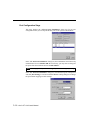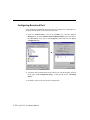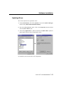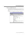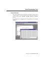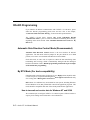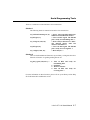
1
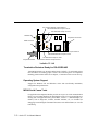
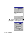
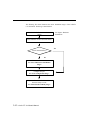
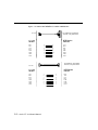
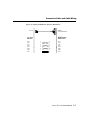
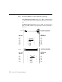
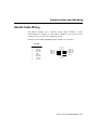
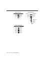
Industio CT-114I User’s Manual 3 in 1 RS-232/422/485 Industrial Serial Board for CompactPCI Bus Mar. 1999 (1st Edition) The content of this manual is also available at Moxa Web Site. Moxa Technologies Co., Ltd. Tel: +866-2-8665-6373 Fax: +886-2-8665-6372 www.moxa.com [email protected] Industio CT-114I User’s Manual The product described in this manual is furnished under a license agreement and may be used only in accordance with the terms of the agreements. Copyright Notice Copyright 1999, Moxa Technologies Co., Ltd. All rights reserved. Reproduction in any form without permission is prohibited. Trademarks MOXA is a registered trademark of Moxa Technologies Co., Ltd. All other trademarks or registered marks in this manual belong to their respective manufacturers. Disclaimer Information in this document is subject to change without notice and does not represent a commitment on the part of Moxa. Moxa provides this document “as is”, without warranty of any kind, either expressed or implied, including, but not limited to, the particular purpose. Moxa may make improvements and/or changes in this manual or in the product(s) and/or the program(s) described in this manual at any time. Information provided in this manual is intended to be accurate and reliable. However, Moxa Technologies assumes no responsibility for its use, or for any infringements of rights of the fourth parties which may result from its use. This product could include technical or typographical errors. Changes are periodically made to the information herein; these changes may be incorporated in new editions of the publication. MOXA Internet Services Customer’s satisfaction is always our number one concern. To ensure that customers get the full benefit of our services, Moxa Internet Services have been built for technical support, product inquiry, new driver update, user’s manual update, etc. The followings are the services we provide. E-mail for technical support address: [email protected] FTP site for free driver update address: ftp.moxa.com or ftp.moxa.com.tw user ID: ftp password: your_email_address World Wide Web (WWW) Site for product info address: www.moxa.com or www.moxa.com.tw About This Manual This manual is composed of six chapters and one appendix. This manual is written for installer, system administrator and software programmer. If you are a first-time installer and system administrator, we recommend you to go through the whole manual except Chapter 4. If you are a software programmer, you may refer to chapter, “Serial Programming Tools”. If you need cable wiring information, please see chapter, “Connection Cable and Cable Wiring”. If you encounter any problem during installation, please refer to chapter, “Troubleshooting”. Chapter 1 Introduction Overview and features for the Industio CT-114I are described. Also check list and overall installation guide. Chapter 2 Hardware Installation Hardware installation for the Industio CT-114I is detailed. Chapter 3 Software Installation Software installation, configuration, driver loading/unloading, driver upgrade and removal for various operating systems: Windows NT and Windows 95/98. Chapter 4 Serial Programming Tools Roughly describing the programming tools for various O.S. platforms, including PComm under Windows NT and Windows 95/98. Also RS-485 programming issue is covered. Chapter 5 Connection Cable and Cable Wiring Describing the RS-232 and RS-422/485 cable wiring. Chapter 6 Troubleshooting Describing the problems and possible answers for the Industio CT-114I. Appendix Specification details, CompactPCI and UART are described. Table of Contents Introduction ...............................................................................................1-1 Overview................................................................................................................1-1 Features.................................................................................................................1-3 Check List ..............................................................................................................1-4 Installation Guide...................................................................................................1-4 Hardware Installation ...........................................................................2-1 First Thing to Do: Interface Settings ......................................................................2-1 Installing the Industio CT-114I Board......................................................................2-2 Connecting the Fan-out Cable ...............................................................................2-3 Software Installation.............................................................................3-1 Windows NT ..........................................................................................................3-1 Installing Driver ..................................................................................................3-2 Configuring Board and Port ...............................................................................3-7 Adding/Removing Board ....................................................................................3-8 Updating Driver ..................................................................................................3-8 Removing Driver ................................................................................................ 3-8 Windows 95/98 ......................................................................................................3-9 Installing Driver ..................................................................................................3-9 First Time Driver Installation Stage ..........................................................................3-11 Port Configuration Stage .........................................................................................3-14 Board and Port Ready Stage ...................................................................................3-16 Configuring Board and Port .............................................................................3-18 Updating Driver ................................................................................................ 3-19 Removing Driver .............................................................................................. 3-20 Serial Programming Tools ...................................................................4-1 PComm Installation...................................................................................................4-1 PComm Programming Library ...................................................................................4-2 Utilities ...................................................................................................................4-2 RS-485 Programming ............................................................................................ 4-6 Automatic Data Direction Control Mode (Recommended)..................................4-6 By RTS Mode (For back-compatibility)............................................................... 4-6 Connection Cable and Cable Wiring ........................................................5-1 RS-232 Cable Wiring............................................................................................. 5-1 RS-422 Cable Wiring............................................................................................. 5-5 RS-485 Cable Wiring............................................................................................. 5-7 Impedance Matching and Termination Resistors ...................................................5-8 DB44 Connector ....................................................................................................5-9 Troubleshooting .......................................................................................6-1 General Troubleshooting ....................................................................................... 6-1 Windows NT ..........................................................................................................6-2 Windows 95/98 ......................................................................................................6-3 Technical Reference............................................................................. A-1 Specification ......................................................................................................... A-1 CompactPCI.......................................................................................................... A-1 UART 16C550C .................................................................................................... A-2 1 1 Introduction Overview Industio - Industrial Multiport Async Solutions for CompactPCI The Industio CT-114I is an RS-232/RS-422/RS-485 4-port serial communication interface board for 32-bit CompactPCI in Eurocard 3U size and with “Plug and Play” feature. The Industio CT-114I supports all three serial interfaces, RS-232, RS-422 and RS-485, in one board. Two of the four ports are RS-232 ports and the other two ports can be configured to RS-232 or RS-422/485 individually. With this versatile design, it can control different kinds of serial device, such as modems, CNC and other industrial machines, without the need to use interface converters. CompactPCI Solution The CompactPCI standard is electrically identical to the PCI bus but has been enhanced to support more rugged industrial environments. The board complies with PCI Spec. 2.1 and has neither switch nor jumper. The BIOS automatically assigns the hardware configuration for the IRQ number and memory addresses. Hence, you must plug the board before installing the software driver. For more PCI information, consult the appendix, “Technical Reference”. Automatic Data Direction Control for RS-485 To ease the 2-wire RS-485 half-duplex control, Automatic Data Direction Control intelligence is built on Industio CT-114I board. Eliminating the need of software interference. Hence, the applications can manage the RS-485 port without extra code to control the half-duplex protocol. Industio CT-114I User's Manual 1-1 JP1: Interface Selection Jumper forPort 2 RS-422/485 Selection Jumper for Port 2 JP2: Data Mode Jumper for Port 2 TxD/RxD LED RS-232 JP1 RS-422 RS-485 CompactPCI Connector Port2 DB44 Connector RS-485 AUTO JP2 RS-232 RS-422 RTS RS-422 RS-485 JP5 JP6 JP3 Port1 RS-485 AUTO JP4 RS-422 RTS JP5/6: Termination Resistor Jumper forPort 2/1 RS-422/485 Selection Jumper for Port 1 JP4: Data Mode Jumper for Port 1 CompactPCI Handle JP3: Interface Selection Jumper for Port 1 Industio CT-114I Termination Resistors Ready for RS-422/RS-485 Termination Resistors are already installed on the Industio CT-114I boards and no more headaches for finding proper resistors and connecting them for impedance matching problem. More details are in chapter, “Connection Cable and Cable Wiring”. Operating System Support Support for Windows NT and Windows 95/98 with user-friendly installation, configuration and performance. MOXA Serial Comm Tools For application development, MOXA provides an easy-to-use serial communication library (PComm) under Windows NT and Windows 95/98. You can use this library to develop your own applications using Visual Basic, Visual C++, Borland Delphi, etc. Utilities, such as diagnostic, monitor, terminal emulator, etc., are included for debugging or monitoring the communication status or terminal emulator, or even file transferring. 1-2 Industio CT-114I User's Manual Introduction Broad Applications The board is suitable for many applications. Here are a few: l Industrial automation l Test and measurement system l Medical equipment data collection l Environment monitoring system Features The Industio CT-114I features: v v v v v v v v v v v v Support CompactPCI, Plug and play, no switch, no jumper, easy installation Support all three serial interfaces in one board (2 ports for RS-232, 2 ports for RS-232 or RS-422/485). ASIC design, low failure rate Compact size design, half-size. High speed TI550C Communication Controllers with on-chip hardware flow control guarantees no data loss. High speed up to 921.6K bps TxD/RxD LEDs for easy monitoring. Support optical isolation, max. 2000V (RS-422/485) Support 2-wire RS-485 half-duplex operation. Support automatic data direction control (RS-485). Termination Resistors already installed on-board, no headache for impedance matching. Compatible with PC standard COM ports. Powerful Serial Comm tool¡Ð PComm Support popular OS¡Ð Windows NT, Windows 95/98 CT-114I Windows NT Windows 95/98 3 3 3: Driver supported by Moxa and shipped with product Note: Download the newest drivers from the MOXA FTP service Industio CT-114I User's Manual 1-3 Check List Upon unpacking the Industio CT-114I, you should find items in the package: v v v v Industio CT-114I 4 port serial board Device driver diskettes: l Windows NT and Windows 95/98¡Ñ 1 l PComm Lite¡Ñ 1 Industio CT-114I User’s Manual (This manual) Fan out cable DB44 to DB9¡Ñ 4 Installation Guide This section gives a brief summary of how to install the Industio CT-114I under each supported operating system. The installation is simple and involves the following stages: Check the CompactPCI BIOS settings Install the Industio CT-114I board and the connection cable See Chapter 2 Install the software from the diskette Configure the driver for the board and ports See respective O.S. Section in Chapter 3 Connect the devices with the cable See Chapter 5 for cable wiring Restart the system Check the driver initialization status If the system restart successfully, you may Develop your applications or Execute the desired applications See Chapter 3 “Software Installation” 1-4 Industio CT-114I User's Manual See Chapter 4, “Serial Programming Tools” 2 Hardware Installation 2 The installation of the Industio CT-114I consists of hardware and software installation. The respective sections of the operating systems in the next chapter deal with the software installation. The hardware installation is detailed in this chapter. JP1: Interface Selection Jumper forPort 2 RS-422/485 Selection Jumper for Port 2 JP2: Data Mode Jumper for Port 2 TxD/RxD LED RS-232 RS-422 RS-485 JP1 CompactPCI Connector Port2 DB44 Connector RS-485 AUTO JP2 RS-422 RTS RS-422 RS-485 RS-232 JP5 JP6 JP3 Port1 RS-485 AUTO JP4 RS-422 RTS JP5/6: Termination Resistor Jumper forPort 2/1 RS-422/485 Selection Jumper for Port 1 JP4: Data Mode Jumper for Port 1 CompactPCI Handle JP3: Interface Selection Jumper for Port 1 Industio CT-114I First Thing to Do: Interface Settings Before installing the board into the slot, you should set all the jumpers to what you want. The default (factory) settings: Port 3 and Port 4 always RS-232; Port 1 and Port 2 RS-485, Automatic Data Direction Control mode, no Termination Resistor, indicated as *. 2-1 Industio CT-114I User's Manual l l l l JP3/1 Interface Selection Jumper for Port 1/2: Right * Set the port interface to RS-485/RS-422. Left Set the port interface to RS-232. RS-422/485 Selection Jumper for Port 1/2: Right * Set the port interface to RS-485. Left Set the port interface to RS-422. JP4/2 Data Mode Selection Jumper for Port 1/2: (Valid if JP3/1 is Right) Right Set the RS-485 port to By RTS Mode. Left* Set the RS-485 port to Automatic Data Direction Control Mode. JP5/6 Termination Resistor Port 2/1: (Valid if JP3/1 is Right) Open * Not using Termination Resistor Short Using Termination Resistor Installing the Industio CT-114I Board The BIOS automatically assigns the IRQ number and I/O addresses for the Industio CT-114I board. Hence, it is a must to have the board plugged first before installing the software driver. After this, simply install the control board into the PC and then connect the connection cable. Step 1: Power off the PC. Warning ! Make sure your system is switched off before you start installing any board. If you don’t, you may risk damaging your system and the board. Step 2: Remove the slot cover bracket if present. Step 3: Plug the Industio CT-114I control board firmly into a free 32-bit CompactPCI slot. Step 4: Fasten the CompactPCI handle to fix the board in place. 2-2 Industio CT-114I User's Manual Hardware Installation Connecting the Fan-out Cable Step 5: Connect the fan-out cable (DB44 to DB9 x 4). Fan-out Cable Industio CT-114I Step 6: Power on the PC and the BIOS will automatically set the IRQ and I/O address. Note ! Each board must occupy one unique IRQ and four 8-byte I/O addresses, which are assigned automatically by the BIOS. However, you can select a free IRQ number manually via the PC’s BIOS setup for the CompactPCI slot, but normally this method is not available for the I/O address. The possible IRQ numbers are 2, 3, 4, 5, 7, 10, 11, 12, and 15. The possible I/O addresses are from 0x0000 to 0xFFFF. Step 7: Proceed with the software installation detailed in the next chapter, “Software Installation”. Industio CT-114I User's Manual 2-3 2-4 Industio CT-114I User's Manual 3 3 Software Installation In this chapter, the software driver installation, configuration and driver update/removal procedures are described for various operating systems, including Windows NT and Windows 95/98. Before proceeding with the software installation, complete the hardware installation detailed in previous chapter. However, if it is necessary for you to develop your own applications, please refer to the next chapter, “Serial Programming Tools”, for serial programming issues. Windows NT Windows NT supports up to 256 serial ports, from COM1 to COM256. To fully integrate the advanced features of Windows NT, multi-process and multi-thread, pure 32-bit Windows NT device drivers are developed for the Industio CT-114I and other MOXA multiport boards. The drivers conform to Win32 COMM API standard. If you install the driver for the first time, please go directly to the section “Installing Driver”. If you have already installed the driver and want to re-configure the board and port, please refer to the section, “Configuring Board and Port”. If you have already installed the driver and want to add or delete boards, please refer to the section, “Adding/Removing Board”. If you want to update or even remove the driver, please go to the section, “Updating Driver”, or the section, “Removing Driver”. 3-1 Industio CT-114I User's Manual Installing Driver Following is the procedure for installing the Industio CT-114I driver for the first time under Windows NT 3.51/4.0. Make sure the board(s) has(have) already been plugged in the system CompactPCI slot(s). 1. Please log in NT as Administrator. 2. Open the [Control Panel], click on the [Network] icon and select the [Adapters] tab. 3. Click on the [Add] button, then the [Have Disk...] button in “Select Network Adapter”. 4. Specify the exact path of the driver diskette, A:\WINDOWS.NT. Then click [OK]. 3-2 Industio CT-114I User's Manual Software Installation 5. Select “MOXA Smartio/Industio Family multiport board” in the “Select OEM Option” dialog box, and click [OK] enter the “Moxa Configuration Panel” dialog box to start the installation. 6. In the “Moxa Configuration Panel” dialog box, click [Add] to enter “Property” dialog box to add the Industio CT-114I Series board. Select the “CT-114 Series” in the “Board Type” field. In the “Property” dialog box, the COM number field of the newly installed board is set to default COM No. If necessary, you may select to change all the ports of the board with the desired “COM Number”. Industio CT-114I User's Manual 3-3 Note ! You may go directly to the step 8 if you need not change any setting. 7. In the “Property” dialog box, select the desired port in the port list and click [Port Setting] to enter the individual “Port #” setting dialog box to change the port number mappings or FIFO settings. 3-4 Industio CT-114I User's Manual Software Installation l Port Number You have to set up all the ports of the board with the desired “COM number”, which should not conflict with other COM number in use. In this “Individual Port Setting” dialog box, you may have two ways to map the physical ports to COM numbers depending on the check box “Auto Enumerating COM Number”. If “Auto Enumerating COM Number” is checked and specify the COM number of the first port, subsequent ports are mapped to continuous COM numbers. For instance, if first port is mapped to COM3, then second port is mapped to COM4 sequentially. If “Auto Enumerating COM Number” is not checked, specify the COM number for individual port. For instance, the second port can be out of sequence, say COM10, while the first port is mapped to COM3. l Rx FIFO Trigger Rx FIFO trigger levels, at 1, 4, 8 or 14 bytes, are available, and the default value is 14 bytes. l Tx FIFO Size Tx FIFO sizes from 1 to 16 bytes are available, and the default value is 16 bytes. 8. Click [OK] in the “Port #” and the “Property” dialog boxes to go back to the “Moxa Configuration Panel” dialog box. Note ! If you need to install more than one board, click [Add] and repeat steps 6 to 8 to configure another board. Up to four Industio CT-114I Series boards can be installed in a system. Click [OK] to finish the configuration. Industio CT-114I User's Manual 3-5 9. When configuration is done, click on [Close] button in the “Network Settings” dialog box. 10. Restart Windows NT system. The latest configuration will not take effect unless the system restarts. Note ! The latest configuration will not take effect unless the system restarts. 11. Once the system restarts, you may check the event log issued by the MOXA driver to see if the ports of the board are initialized successfully. l Enter the [Administrative] group, click on the [Event Viewer] icon and select [Log] and [System] to check a message similar to “MOXA CT-114I, with serial ports COM3 to COM6, has been enabled” for each configured board. l If an error message similar to “Cannot find any configured MOXA CT114I board!” appears, refer to the “Troubleshooting” chapter for solutions. 3-6 Industio CT-114I User's Manual Software Installation Note ! Once the board and the driver are installed and the driver restarts successfully, you can start to develop applications with the PComm library (See “Serial Programming Tools”) or the Microsoft Win32 API. You can also execute any ready-made applications, such as PComm utility Terminal emulator (See “Serial Programming Tools”) or HyperTerminal to transmit/receive data, as well as Remote Access Service to provide dial-up networking capabilities. Configuring Board and Port If you already have installed the driver and want to re-configure the ports, please follow this procedure. 1. In the [Control Panel], click on the [Network] icon and select the [Adapters] tab. 2. Select “MOXA Smartio/Industio Family Adapter” in “Network Adapters”. Industio CT-114I User's Manual 3-7 3. Click on the [Properties] button to open the “Moxa Configuration Panel” dialog box. Please see steps 6-10 in the previous section, “Installing Driver”, for more details. Adding/Removing Board Following is the procedure to add/remove Industio CT-114I boards after a first time installation. Note that the presence of the board(s) is(are) required for adding/removing boards. 1. 2. 3. 4. Power off the system. Plug/unplug the boards in the system. Power on the system. Run the software configuration to setup the boards, as shown in the previous section. Updating Driver To update the driver for the Industio CT-114I board, simply remove the driver, as described in the next section, and then reinstall it as detailed in the “Installing Driver” section. Removing Driver To remove the driver for the Industio CT-114I board, 1. Open the [Control Panel], click on the [Network] icon, and select the [Adapters] tab. 2. Select “MOXA Smartio/Industio Family Adapter” in the adapter list, then click on the [Remove] button and the [OK] button to remove the driver. 3. Restart the system to activate the new configuration. 3-8 Industio CT-114I User's Manual Software Installation Windows 95/98 Windows 95/98 supports up to 128 serial ports, from COM1 to COM128. To fully integrate the advanced features of Windows 95, multi-process and multi-thread, pure 32-bit Windows 95 virtual device port drivers (VxD) compliant with communication drivers (VCOMM) are developed for the Industio CT-114I and other MOXA multiport boards. The drivers conform to the Win32 COMM API standard. If you install the driver for the first time, or you want to add more boards, please go directly to section, “Installing Driver”. If you have already installed the driver and want to re-configure the board, please refer to section, “Configuring Board and Port”. If you want to update the driver, please go to section, “Updating Driver”. If you want to remove the driver, please go to the section, “Removing Driver”. Installing Driver If you install for the first time, or you want to add more boards, this section is for you. You can easily plug the Industio CT-114I board and work right away with very little installation efforts under Windows 95/98, which supports Plug and Play capability. Windows 95/98 will automatically detect the presence of the newly plugged board and prompt you to install the software driver the first time. In this case, you need the driver diskette. Up to 4 Industio CT-114I boards can be installed together as long as the I/O addresses and IRQ number resources are sufficient and available in a system. Industio CT-114I User's Manual 3-9 The following flow chart illustrates the driver installation stages of the Industio CT-114I boards. Each stage is detailed later. Install the Industio PCI board in the system See chapter “Hardware Installation” Start Windows 95/98 to detect the board Yes Driver installed before? No Install the driver with the diskette See “First Time Driver Installation Stage” Configure the port See “Port Configuration Stage” The ports of the Industio CT-114I Series board are ready to work. See “Board and Port Ready Stage” 3-10 Industio CT-114I User's Manual Software Installation First Time Driver Installation Stage This stage presents the steps for installing the driver for the very first time with the first Industio CT-114I board. The installation of the Industio CT-114I board for Windows 95 and Windows 98 differs slightly and will be described in two columns. Follow the steps in the left or right column for Windows 95 or 98, respectively. 1. Upon detecting the first new Industio CT-114I board, Windows 95/98 will automatically show a “New hardware found” message box, and then display the following dialog box. Click on the [Next>] button. Windows 95 Windows 98 2. Click on the [Other Locations] button. 2. Select “Display a list...” and click [Next>]. Industio CT-114I User's Manual 3-11 3. Type “A:\Windows.95” in the Location field, and click [OK]. The system will start reading the files from the diskette. 3. Select “Other Devices” and click [Next>]. 4. Clink on the [Finish] button. 4. Click on the [Have Disk] button. 5. Type “A:\Windows.95” and click [OK]. The system will start reading the files from the diskette. 3-12 Industio CT-114I User's Manual Software Installation 6. Click [Next>]. 7. Click [Next>]. Industio CT-114I User's Manual 3-13 Port Configuration Stage This stage displays the “CT-114 Series Installation” dialog box for the port configuration. Here you can map the MOXA ports to the system COM numbers. In the “CT-114 Series Installation” dialog box, the COM number field of the newly installed board is set to default COM No. If necessary, you may select to change all the ports of the board with the desired “COM Number”. Note ! You may go directly to the next stage if you need not change any setting. In the “CT-114 Series Installation” dialog box, select the desired port in the port list and click [Port Setting] to enter the individual “Port #” setting dialog box to change the port number mappings or FIFO settings. 3-14 Industio CT-114I User's Manual Software Installation l Port Number You have to set up all the ports of the board with the desired “COM number”, which should not conflict with other COM number in use. In this “Individual Port Setting” dialog box, you may have two ways to map the physical ports to COM numbers depending on the check box “Auto Enumerating COM Number”. If “Auto Enumerating COM Number” is checked and specify the COM number of the first port, subsequent ports are mapped to continuous COM numbers. For instance, if first port is mapped to COM3, then second port is mapped to COM4 sequentially. If “Auto Enumerating COM Number” is not checked, specify the COM number for individual port. For instance, the second port can be out of sequence, say COM10, while the first port is mapped to COM3. l Rx FIFO Trigger Rx FIFO trigger levels, at 1, 4, 8 or 14 bytes, are available, and the default value is 14 bytes. l Tx FIFO Size Tx FIFO sizes from 1 to 16 bytes are available, and the default value is 16 bytes. Industio CT-114I User's Manual 3-15 Board and Port Ready Stage Click [OK] for all the dialog boxes to finish the configuration and exit the “CT-114 Series Installation” dialog box. In this last stage, you will complete the driver installation. Windows 95 Windows 98 After the port installation, you can immediately use the COM ports of the Industio CT-114I board without restarting Windows 95 system. After the port installation, click on the [Finish] button. Now you can immediately use the COM ports of the Industio CT-114I board without restarting Windows98 system. Once the installation is finished, error conditions of the board, if any, are displayed on the screen. Otherwise, everything should be fine. If an error message similar to “CT-114I (BusNo=x, DevNo=x, Starting COM=x) interrupt number is invalid!” appears, consult the “Troubleshooting” chapter. Note ! Up to now, the driver installation of the Industio CT-114I is complete and successful, including the board and port configuration. However, if changes of the board and port configuration are needed, please refer to the next section, “Configuring the Board and Port”, for more configuration details. 3-16 Industio CT-114I User's Manual Software Installation Note ! Once the board and the driver are installed and the driver restarts successfully, you can start to develop applications with the PComm library (See “Serial Programming Tools”) or the Microsoft Win32 API. You can also execute any ready-made applications, such as PComm utility Terminal emulator (See “Serial Programming Tools”) or HyperTerminal to transmit/receive data, as well as Remote Access Service to provide dial-up networking capabilities. l If multiple boards are installed at the same time, the same scenario applies for the next boards, except that no driver diskette is asked anymore. l Similarly, if you want to add more boards and the driver has been installed before, simply plug the Industio CT-114I board and Windows 95/98 will automatically detect and install the required driver. Industio CT-114I User's Manual 3-17 Configuring Board and Port If you already have installed the driver and want to re-configure the COM number for the ports under Windows 95/98, follow this procedure. 1. Open the [Control Panel], click on the [System] icon, select the [Device Manager] tab, and then [MOXA Smartio/Industio Family]. Select the desired [CT-114 Series] entry, click on the [Properties] button and select the [Ports Configuration] tab. è 2. Assign the desired COM number for the Industio CT-114I port mapping, detailed in the stage, “Port Configuration Stage”, of the previous section, “Installing Driver”. 3. Restart the system to activate the latest configuration. 3-18 Industio CT-114I User's Manual Software Installation Updating Driver This section explains how to update the driver. 1. In the [Control Panel], click on the [System] icon, select the [Device Manager] tab and select [MOXA Smartio/Industio Family]. 2. Select the “CT-114 Series” option. Click on the [Properties] button and then select the [Device Driver] tab. 3. Click on the [Update Driver...] button. Click then on the [Have Disk...] button to type the path of the new driver and update the driver. è 4. Restart the system to activate the new configuration. Industio CT-114I User's Manual 3-19 Removing Driver This section explains how to remove the Industio CT-114I driver. To remove the Industio CT-114I board, 1. Open the [Control Panel] and click on the [System] icon. Select the [Device Manager] tab and [MOXA Smartio/Industio Family]. 2. Select the desired Industio CT-114I board and click on the [Remove] button. Click [OK] when asked to confirm the removal of the board. 3. Click [Yes] to shutdown Windows 95/98 when the system prompts you to reboot. 4. Turn off the power and physically remove the CompactPCI board from the expansion slot. 3-20 Industio CT-114I User's Manual 4 4 Serial Programming Tools Moxa supports some easy but powerful serial programming libraries and communication troubleshooting utilities under Windows NT and Windows 95/98. You will save a lot of developing time with the MOXA Serial Programming Tools. The following sections will detail the installation, the library and the utilities for various platforms. PComm, the professional serial comm tool for PC, is a software package for Windows NT and Windows 95/98. It consists of a powerful serial communication library for easy programming in the most popular languages, useful utilities such as diagnostic, monitor and terminal emulator, illustrative sample programs and comprehensive on-line documents. The serial communication library is useful for developing a system for data communication, remote access, data acquisition or industrial control in the Windows NT and Windows 95/98 environment, for an easier solution compared to the more complex Windows Win32 COMM API. PComm Installation To install PComm, run \Setup.exe from the diskette. Note that the PComm diagnostic and monitor utilities are for MOXA boards only. MOXA Windows NT or Windows 95/98 device drivers, as well as MOXA boards are required. The drivers are installed separately and detailed in the “Software Installation” chapter. Click [Start] and select [Program Files] and the [PComm Lite] group to see a list of utilities and documents. Industio CT-114I User's Manual 4-1 PComm Programming Library The serial communication library helps you to develop programs for serial communications for any COM port complying with Microsoft Win32 API. It facilitates the implementation of multi-process and multi-thread serial communication programs and hence greatly reduces developing time. For a complete library function description and sample programs for Visual C++, Visual Basic and Delphi, please click [Start] and select [Program Files] and [PComm Lite] and [PComm Library Help], [PComm Porting Notes] or [PComm Programming Guide] or refer to the sample programs in the PComm directory. Utilities Following are short descriptions of each utility. For details, please see the on-line help on the diskette. 4-2 Industio CT-114I User's Manual Serial Programming Tools Diagnostic (for MOXA boards only) A convenient diagnostic program that provides internal and external testing, such as IRQ, TxD/RxD, UART, CTS/RTS, DTR/DSR, DTR/DCD testing, etc., for the MOXA boards and ports to verify correct operations of both the software and hardware. Click [Start] and select [Program Files] and [PComm Lite] and [Diagnostic]. Industio CT-114I User's Manual 4-3 Monitor (for MOXA boards under Windows NT Only) A useful port status monitoring program that allows you to watch the selected MOXA COM ports’ data transmitting/receiving throughput and communication line status which are updated and displayed on the screen at time intervals. You can also click on one of the specific displayed port in order to visualize the current communication parameters and status of that port. Click [Start] and select [Program Files] and [PComm Lite] and [Monitor]. 4-4 Industio CT-114I User's Manual Serial Programming Tools Terminal Emulator The Terminal Emulator features multi-windows and supports terminal types of VT100 and ANSI. You can transfer data interactively, send pattern periodically or transfer file using ASCII, XMODEM, YMODEM, ZMODEM and KERMIT protocols. Click [Start] and select [Program Files] and [PComm Lite] and [Terminal Emulator]. Industio CT-114I User's Manual 4-5 RS-485 Programming If you intend to do RS-485 communication with Industio CT-114I Series, please follow the RS-485 programming guide below and also refer to the chapter, “Connection Cable and Cable Wiring”, for more RS-485 operation details. The Industio CT-114I Series supports only 2-wire half-duplex RS-485 communication. Data+/- pins are served for both data transmitting and receiving, depending on the mode selected: either Automatic Data Direction Control or By RTS mode. Automatic Data Direction Control Mode (Recommended) Automatic Data Direction Control scheme is the best solutions for RS-485 applications. The data mode selection jumper for the port should be set to Left position, to be able to use Automatic Data Direction Control Mode. Under this mode, no extra code is required to control the data transferring (data transmitting and receiving), which is automatically managed with the intelligent hardware mechanism. That is, RS-485 programming in this mode is just as simple as RS-232/RS-422 programming. By RTS Mode (For back-compatibility) If the data mode selection jumper for the port is set to Right position, By RTS mode is used. The port is ready for transmitting data if RTS signal is asserted and ready for receiving data if RTS signal is not asserted. RTS scheme is a traditional way and suitable for most system, including Windows NT and Windows 95/98, that permits RTS control from application programs. This mode should be compatible with most of the already-made RS-485 applications. How to transmit and receive data for Windows NT and 95/98 We recommend you to configure Industio CT-114I Series ports as follows in order to acquire precise timing control in RS-485 2-wire transmission. 4-6 Industio CT-114I User's Manual Serial Programming Tools There are 2 solutions to control RS-485 2-wire transmission. Solution 1 The following model is common in RS-485 2-wire transmission. sio_SetWriteTimeouts(port, 0); sio_RTS(port, 1); sio_write(port, buff, 10); sio_RTS(port, 0); sio_read(port, buff, 10); /* Set sio_write() into block mode if for Windows NT and Windows 95/98 */ /* Turn on RTS signal. The RS-485 port is ready for transmitting data. */ /* Write 10 byte characters in "buff". The function blocks until last character transmitted */ /* Turn off RTS signal. The RS-485 port is ready for receiving data. */ /* Read 10 bytes */ Solution 2 There is a dedicated RS-485 function in PComm library. It integrates the above functions of solution 1 regarding sending data as one. sio_putb_x(port, buff, tick ); /* 1. Turn on RTS and ready for transmitting data. 2. Send data. 3. Wait for tick time. 4. Turn off RTS and ready for receiving data. */ For more information on these functions, please refer to PComm library on-line Help file for Windows NT and Windows 95/98. Industio CT-114I User's Manual 4-7 4-8 Industio CT-114I User's Manual 5 5 Connection Cable and Cable Wiring In serial data communications, the term DTE is for Data Terminal Equipment, like PC COM1/2, serial printers and terminals. The term DCE is for Data Communication Equipment, like modems. RS-232 Cable Wiring The followings are pin assignments for the DB9 RS-232 connector for Port 3 and Port 4 of Industio CT-114I Series. CT-114I (DTE, DB9 Male) 1 2 3 4 5 6 7 8 DCD RxD TxD DTR GND DSR RTS CTS Industio CT-114I User's Manual 5-1 Type 1: To connect the Industio CT-114I to a DTE device. PC COM2 port, Serial Printer, Terminal, or any DTE Device CT-114I CT-114I DTE Device DB9 Male DB25 Male RxD TxD CTS RTS DTR DSR GND DCD 2 3 8 7 4 6 5 1 2 3 4 5 6 20 7 8 TxD RxD RTS CTS DSR DTR GND DCD CT-114I PC COM2 port, Serial Printer, Terminal, or any DTE device CT-114I DTE Device DB9 Male DB9 Male TxD RxD RTS CTS DSR DTR GND DCD 5-2 Industio CT-114I User's Manual 3 2 7 8 6 4 5 1 2 3 8 7 4 6 5 1 RxD TxD CTS RTS DTR DSR GND DCD Connection Cable and Cable Wiring Type 2: To connect Industio CT-114I to a DCE device. Modem or any DCE Device CT-114I CT-114I DCE Device DB9 Male DB25 Female RxD TxD CTS RTS DTR DSR GND DCD 2 3 8 7 4 6 5 1 2 3 4 5 6 20 7 8 RxD TxD CTS RTS DTR DSR GND DCD Industio CT-114I User's Manual 5-3 Type 3: To connect Industio CT-114I to a DTE with 3-pin wiring. If the [Hardware flow control] feature is set to “ON”, you must loop back (or short) the RTS with CTS and the DSR with DTR, DCD on the MOXA site. If [Hardware flow control] feature is set to “OFF”, you could just leave RTS, CTS, DSR, DTR, DCD open, ignoring the connection indicated in dash-lines. PC COM2 port, Serial Printer, Terminal, or any DTE Device CT-114I CT-114I DTE Device DB9 Male DB25 Male TxD RxD GND RTS CTS DTR DSR DCD 3 2 5 7 8 4 6 1 2 3 7 4 5 20 6 8 TxD RxD GND RTS CTS DTR DSR DCD PC COM2 port, Serial Printer, Terminal, or any DTE device CT-114I CT-114I DTE Device DB9 Male DB9 Male TxD RxD GND RTS CTS DSR DTR DCD 5-4 Industio CT-114I User's Manual 3 2 5 7 8 6 4 1 3 2 5 7 8 6 4 1 TxD RxD GND RTS CTS DSR DTR DCD Connection Cable and Cable Wiring RS-422 Cable Wiring The RS-422 standard uses a balanced voltage digital interface to allow communications of 10M bps on cable length of 4000 feet. Ten receivers can be connected to any one driver for broadcasting systems. RS-422 pin outs for Port 1 and Port 2 of the Industio CT-114I Series: CT-114I 1 2 3 4 5 6 7 8 9 TxD-(A) TxD+(B) RxD+(B) RxD-(A) GND RTS-(A) RTS+(B) CTS+(B) CTS-(A) RTS-(A) RTS+(B) CTS+(B) CTS-(A) 6 7 8 9 1 2 3 4 5 TxD-(A) TxD+(B) RxD+(B) RxD-(A) GND Industio CT-114I User's Manual 5-5 RS-422 Point-to-point CT-114I 2 TxD+(B) 1 TxD-(A) 3 RxD+(B) 4 RxD-(A) 5 GND RS-422 Device RxD+(B) RxD-(A) TxD+(B) TxD-(A) GND RS-422 Broadcasting CT-114I 2 TxD+(B) 3 RxD+(B) 1 TxD-(A) 4 RxD-(A) 5 GND RS-422 Device 1 RxD+(B) TxD+(B) RxD-(A) TxD-(A) GND RS-422 Device N RxD+(B) TxD+(B) RxD-(A) TxD-(A) GND RS-422 with Handshaking CT-114I 2 TxD+(B) 1 TxD-(A) 3 RxD+(B) 4 RxD-(A) 5 GND 7 RTS+(B) 6 RTS-(A) 8 CTS+(B) 9 CTS-(A) 5-6 Industio CT-114I User's Manual RS-422 Device RxD+(B) RxD-(A) TxD+(B) TxD-(A) GND CTS+(B) CTS-(A) RTS+(B) RTS-(A) Connection Cable and Cable Wiring RS-485 Cable Wiring The RS-485 standard is an enhanced version of the RS-422 balanced line standard. It allows multiple drivers and receivers in a multidrop systems. As many as 32 drivers and 32 receivers can be put on any multidrop system. The Industio CT-114I Series supports only 2-wire half-duplex RS-485 communication. Data+/- pins are served for both data transmitting and receiving, depending on the RTS signal. RS-485 pin outs for Port 1 and Port 2 of the Industio CT-114I Series: CT-114I 1 2 5 Data-(A) Data+(B) GND 1 Data-(A) 2 Data+(B) 5 GND Multidrop RS-485 Half-duplex CT-114I Master 2 Data+ 1 Data5 GND RS-485 Device 1 Slave Data+ DataGND RS-485 Device N Slave Data+ DataGND See the section “RS-485 Programming” of the chapter “Serial Programming Tools” for more RS-485 programming details. Industio CT-114I User's Manual 5-7 Impedance Matching and Termination Resistors For RS-422/485 serial communications, when an electrical signal travels through two different resistance junctions in a transmission line, the impedance mismatch will sometimes cause signal reflection. Signal reflection causes signal distortion, which in turn will contribute communication errors. The solution to this problem is to establish the same impedance at the line ends as in the line itself by terminating them with resistors. Industio CT-114I already installs the resistors on board for your convenience, indicated as follows. The value of the termination resistor should equal the characteristic impedance of the transmission line. Resistors should be added near the receiving side. Note: Stands for termination resistor near the receiving side. CT-114I 2 1 3 4 7 6 8 9 RS-422/485 Device TxD+(B) TxD-(A) RxD+(B) RxD-(A) RTS+(B) RTS-(A) CTS+(B) CTS-(A) RxD+(B) RxD-(A) TxD+(B) TxD-(A) CTS+(B) CTS-(A) RTS+(B) RTS-(A) JP1: Interface Selection Jumper forPort 2 RS-422/485 Selection Jumper for Port 2 JP2: Data Mode Jumper for Port 2 TxD/RxD LED RS-232 RS-422 RS-485 JP1 CompactPCI Connector Port2 DB44 Connector RS-485 AUTO JP2 RS-422 RTS RS-422 RS-485 RS-232 JP5 JP6 JP3 Port1 RS-485 AUTO JP4 RS-422 RTS JP5/6: Termination Resistor Jumper forPort 2/1 RS-422/485 Selection Jumper for Port 1 CompactPCI Handle JP4: Data Mode Jumper for Port 1 JP3: Interface Selection Jumper for Port 1 Industio CT-114I 5-8 Industio CT-114I User's Manual Connection Cable and Cable Wiring DB44 Connector The following lists the pin assignments of the Industio CT-114I DB44 connector on the bracket. With this information, you may fabricate any type of fan-out cables, such as DB44 to DB9 x 4 or DB44 to DB25 x 4. For RS-232 Mode Pin no. 1 2 3 4 5 6 7 8 9 10 11 12 13 14 15 16 17 18 19 20 21 22 Signal TxD0 RxD0 RTS0 TxD1 RxD1 RTS1 TxD2 RxD2 RTS2 TxD3 RxD3 RTS3 CTS0 DTR0 DSR0 CTS1 DTR1 DSR1 Pin no. 23 24 25 26 27 28 29 30 31 32 33 34 35 36 37 38 39 40 41 42 43 44 Signal CTS2 DTR2 DSR2 CTS3 DTR3 RTS3 DCD0 RI0 GND0 DCD1 RI1 GND1 DCD2 RI2 GND2 DCD3 RI3 GND3 Note: Make shield grounded to connector. Industio CT-114I User's Manual 5-9 For RS-422 Mode Pin no. Signal Pin no. Signal 1 2 3 5 6 7 16 17 18 RxD0+(B) TxD0+(B) RTS0+(B) RxD1+(B) TxD1+(B) RTS1+(B) CTS0+(B) RxD0-(A) RTS0-(A) 20 21 22 31 32 33 35 36 37 CTS1+(B) RxD1-(A) RTS1-(A) TxD0-(A) CTS0-(A) GND0 TxD1-(A) CTS1-(A) GND1 Note: Make shield grounded to connector. For RS-485 Mode Pin no. 2 6 31 Signal Data0+(B) Data1+(B) Data0-(A) Pin no. Signal 33 35 37 GND0 Data1-(A) GND1 Note: Make shield grounded to connector. 5-10 Industio CT-114I User's Manual 6 6 Troubleshooting Common Industio CT-114I problems and possible solutions are listed below. If you still have problems, contact your dealer or Moxa for help. Or use the “Problem Report Form” at the end of this manual to report problems to your dealer at once for faster technical support. General Troubleshooting 1. The MOXA driver, while installing the driver, cannot detect the MOXA CompactPCI board. Hardware causes and solutions: a. The board is not installed or missing (absent). Please install it. b. The board is not properly plugged in the system. If that is the case, re-install the board and make sure that it fits well in a 32-bit CompactPCI slot this time. Sometimes the slot for plugging the board is bad. In this case, try other slots until you find a good one. c. Your motherboard does not have a vacant IRQ for the CT-114I. Please enter BIOS and make sure there are available IRQ in PCI/PnP settings. 2. The MOXA board and driver are activated but cannot transfer (transmitting/receiving) data. Hardware Causes and Solutions: a. Check for wrong cable wiring. Refer to the “Connection Cable and Cable Wiring” chapter for precise pinouts of the connector type you are using. b. The cable or the board are defective. You may use other ports, cables or boards to verify. In addition, the PComm “Diagnostic” utility for Windows NT and Windows 95/98 is good for testing MOXA boards and port conditions. If Diagnostic reports Industio CT-114I User's Manual 6-1 error, replace the faulty components. Software Causes and Solutions: a. For RS-422 mode, Industio CT-114I checks the line status (CTS) before it sends data out if the RTS/CTS flow control feature is set to “Enable” in the configuration or application program. Please refer to the “Connection Cable and Cable Wiring” chapter for proper wiring. b. Perhaps the application controlling the board is not correctly written according to the corresponding API of the operating system. To verify, please run an existing and known good application or the provided utilities by Moxa. For example, under Windows NT and Windows 95/98, Pcomm “Terminal emulator” or “HyperTerminal” utilities are good for testing the COM ports. Windows NT This section is specific for troubleshooting under Windows NT. For general problems and solutions, please see the previous section, “General Troubleshooting”. 1. After the system reboots, the error message “Another driver in the system, which did not report its resources, has already claimed the interrupt used by xxx.” appears in the Event Log. This indicates that the MOXA board is found, but the IRQ is conflicting with another adapter. Please make sure there is no conflict with other adapter’s IRQ. Check the PCI BIOS IRQ settings first. Make sure that an IRQ is available. 2. After the system reboots, the error message “Cannot find any configured MOXA Smartio/Industio PCI Series board!” appears in the Event Log. Please make sure the PCI board is seated firmly in the expansion slot. 3. The COM number of the Industio CT-114I, with device number xx, conflicts with others. The COM numbers of different boards happen to be the same. Try to change the COM number mappings. 6-2 Industio CT-114I User's Manual Troubleshooting 4. Windows NT system panic (blue screen). The possible reason is an IRQ or I/O address conflict with other ISA Bus adapters, like LAN and SCSI boards, or the system BIOS. Please refer to the corresponding problem in the previous section, “General Troubleshooting”, for solutions. Windows 95/98 This section is specific for troubleshooting under Windows 95/98. For general problems and solutions, please see the previous section, “General Troubleshooting”. 1. The system fails to find the Industio CT-114I board! - The board(s) is not plugged properly. - The slot for plugging the board is defective. In this case, please try other slots until you find a good one. - The board might be defective. 2. After the system reboots, the error message “CT-114I (BusNo=x, DevNo=x, Starting COM=x) interrupt number is invalid!” appears. This indicates that the MOXA board is found, but the IRQ is conflicting with other adapter. Make sure there is no conflict with other adapter’s IRQ. Check the CompactPCI BIOS IRQ settings and make sure an IRQ is available. Industio CT-114I User's Manual 6-3 6-4 Industio CT-114I User's Manual Appendix A Technical Reference Specification v v v v v v v v v v v v v v v Bus interface: Number of ports: I/O address: IRQ: Data bits: Stop bits: Parity: UART: Speed (bps): Connectors: Data signals: Isolation protection: Operating temp: Power requirement: Dimensions: 32-bit CompactPCI (Spec 2.1) 2 (RS-232), 2 (RS-232 or RS-422/485) Assigned by BIOS Assigned by BIOS 5, 6, 7, 8 1, 1.5, 2 None, even, odd, space, mark 16C550C or compatible¡Ñ 4 50 ~ 921.6K DB9 (male)¡Ñ 4 RS-232¡Ð TxD, RxD, RTS, CTS, DTR, DSR, DCD, GND RS-422¡Ð TxD(B)+/(A)-, RxD(B)+/(A)-, RTS(B)+/(A)-, CTS(B)+/(A)-, DCD, GND RS-485¡Ð Data(B)+/(A)-, GND Max. 2000V (RS-422/485) 0 ~ 55 ¢J 700mA max. (+5V), 100mA max. (+12V), 120mA max.(-12V) 100 mm¡Ñ 160 mm (3U) CompactPCI The 32-bit Industio CT-114I board complies with the PCI specifications 2.1. The BIOS automatically assigns hardware configuration for IRQ and I/O addresses. Hence, you must first plug the board before installing the software driver. Unlike ISA slots, different CompactPCI slots in the same PC may have different bus numbers and device numbers with respect to the CompactPCI specifications. The same CompactPCI board will have different system configurations if switched to a Industio CT-114I User's Manual A-1 different CompactPCI slot, which may be called slot-sensitive or slot-dependent. This may also apply to CompactPCI slots in PC with different motherboard, which may use different device number sets. For example, some use 17, 18, 19, and 20 for identifying the respective CompactPCI slots but some use 11, 12, 13 and 14. Due to the slot-dependency, it is necessary to re-configure the software driver once the board is plugged in different CompactPCI slots. Up to 4 Industio CT-114I boards are allowed in a system. When installing multiple boards, please note the boards’ order for distinguishing the installed boards. UART 16C550C The UART chip, 16C550C, is an intelligent asynchronous controller capable of supporting one full duplex channel that simultaneously transfers data at 921.6 Kbps. To increase the overall data throughput, special features such as on-chip FIFO and on-chip hardware flow control are used to reduce the number of interrupts to the onboard CPU and to prevent any loss of valuable data. A-2 Industio CT-114I User's Manual Problem Report Form Industio CT-114I Customer name: Company: Tel: Email: Fax: Date: 1. Moxa Product: CT-114I Serial Number: ________________ 2. Moxa Driver Version: ________________ 3. Moxa Hardware Settings: CompactPCI slot number ________________________ 4. Operating System: o Windows 95 o Windows 98 o Windows NT 3.51 o Windows NT 4.0 o Others 5. PC Host: Make _________ Model _________ 6. CPU: Speed _____MHz Make ______ Model ______ 7. BIOS: Make __________________ Version _______ 8. CompactPCI IRQ Configuration in BIOS: 8.1 Please check the hardware configuration for I/O, IRQ from Windows NT or 95/98 system. And also check the switch settings for interface and data mode for each port. PORT I/O IRQ Speed (High/Normal) Interface (RS-232/422/485) RS-485 Data Mode (AUTO/RTS) 1 2 3 4 5 6 7 8 Interrupt Vector: ________ 9. Problem Description: Please describes the problem as clearly as possible, including the error message you see. We may have to follow your description to reproduce the problem. o Board not found. o Board found, but can’t transfer data. o Can transfer data, but lose data. o Can transfer data, but with garbled data. o Others. Detailed error message description is recommended: Return Procedure For product repair, exchange or refund, you must: v Provide evidence of original purchase. v Fill out the Problem Report Form (PRF) as detailed as possible for shorter product repair time. v Obtain a Return Merchandise Authorization (RMA) number from the sales representative or dealer. v Carefully pack the product in an anti-static package, and send it, pre-paid, to the dealer. The RMA number should be visible on the outside of the package, and include a description of the problem along with the return address and telephone number of a technical contact.