1
CN2100 Async Server User’s Manual
Second Edition, June 2008
www.moxa.com/product
© 2008 Moxa Inc., all rights reserved.
Reproduction without permission is prohibited.
CN2100 Async Server User’s Manual
The software described in this manual is furnished under a license agreement and may be used
only in accordance with the terms of that agreement.
Copyright Notice
Copyright © 2008 Moxa Inc.
All rights reserved.
Reproduction without permission is prohibited.
Trademarks
MOXA is a registered trademark of Moxa Inc.
All other trademarks or registered marks in this manual belong to their respective manufacturers.
Disclaimer
Information in this document is subject to change without notice and does not represent a
commitment on the part of Moxa.
Moxa provides this document “as is,” without warranty of any kind, either expressed or implied,
including, but not limited to, its particular purpose. Moxa reserves the right to make improvements
and/or changes to this manual, or to the products and/or the programs described in this manual, at
any time.
Information provided in this manual is intended to be accurate and reliable. However, Moxa
assumes no responsibility for its use, or for any infringements on the rights of third parties that
may result from its use.
This product might include unintentional technical or typographical errors. Changes are
periodically made to the information herein to correct such errors, and these changes are
incorporated into new editions of the publication.
Technical Support Contact Information
www.moxa.com/support
Moxa Americas:
Toll-free: 1-888-669-2872
Tel: +1-714-528-6777
Fax: +1-714-528-6778
Moxa China (Shanghai
office):
Toll-free: 800-820-5036
Tel: +86-21-5258-9955
Fax: +86-10-6872-3958
Moxa Europe:
Tel: +49-89-3 70 03 99-0
Fax: +49-89-3 70 03
99-99
Moxa Asia-Pacific:
Tel: +886-2-8919-1230
Fax: +886-2-8919-1231
About This Guide
This section discusses the audience, objectives and organization of the CN2100 Async Server
User's Manual.
Document Objective and Usage
This manual guides you through the preparation, installation, configuration and troubleshooting
of MOXA Async Server on Windows NT.
Audience
This publication is designed for persons who need to install Moxa Async Server, including users
maintaining NT system with serial applications, software programmers designing programs for
data communication, administrators maintaining Async Server for multi-users. For programmers,
this publication is to be used along with the Moxa PComm manual.
Note: If you are multiport serial board user, and want to use same functions on Async Serve,
please read Chapter 1, 2 and 3 for installation. If you are advanced users and like to enjoy more
benefits from Async Server, please read Chapter 1, 2 and 4. If you like to customize Async Server
for special functions such as WAN connection and backup routing, read Chapter 1, 2, and 5. If
you need shared server installed on your network, read Chapter 4.
Document Organization
The major sections of this publication are as follows:
Chapter 1, "Introduction", general introduction about the CN2100 application types, including
the time to use what kind of operation mode offered by Moxa and its features, specifications.
Chapter 2, "Installation", describes how hardware to be installed and the initial setup.
Chapter 3, "Configuration", describes how to configure the CN2100 and the detailed description
for the relevant tool.
Chapter 4, "Terminal Mode", depicts the terminal operation mode and its facilities:
telnet, rlogin and the description of detailed settings.
Chapter 5, "Integrated SLIP and PPP Operations", describes the SLIP and PPP
operations and the description of detailed settings.
Chapter 6, "Integrated Dynamic Operations", states the Triple Dynamic operation modeand the
description of detailed settings.
Chapter 7, "Async Server Proprietary Protocol", explains how to write the program to control
the async ports from a network host and the description of detailed settings.
Chapter 8, "Networked Printers", provides information on how to setup networked printers and
the description of detailed settings.
Chapter 9, "Reverse Telnet ", describes how to use the Reverse Telnet function and the
description of detailed settings.
Chapter 10, "Transparent RAW Data Transmission ", illustrates how transparent RAW data
transmission work and its configurations.
Chapter 11, "Administrative Utilities ", narrates the useful administrative tools and the detailed
description.
Appendix A, "Troubleshooting", lists the common error condition and its reason as well as the
possible solutions.
Appendix B, "Pin Assignment and Cable Wiring", provides the port pin assignment and cables
wiring.
Appendix C, "TCP/IP and Internet Network", simple introduction to TCP/IP and networks.
Appendix D, "Domain Name Service ", describes the Domain Name Service.
Appendix E, "SNMP MIB Definitions", lists of the supported SNMP groups.
Appendix F, "Moxa Fixed TTY Program" advises users what moxatty means and where to get it
and its manual.
Table of Contents
CHAPTER 1 INTRODUCTION...................................................................................................... 1-1
1.1 OVERVIEW........................................................................................................................1-1
1.2 CHECKLIST .......................................................................................................................1-5
1.3 SYSTEM DESCRIPTION....................................................................................................1-5
1.4 FEATURES .........................................................................................................................1-5
1.5 OUTLOOK .........................................................................................................................1-7
CHAPTER 2 INSTALLATION........................................................................................................ 2-1
2.1A TTACHING TO THE NETWORK .......................................................................................2-1
2.2 A TTACHING CONSOLE TERMINAL .................................................................................2-2
2.3 POWER-UP ........................................................................................................................2-2
2.4 RUNNING THE SYSTEM PROGRAM.................................................................................2-2
CHAPTER 3 CONFIGURATION................................................................................................... 3-1
3.1 W INDOW -LIKE CONSOLE............................................................................................3-3
3.2 SERVER..............................................................................................................................3-5
3.3 HOST .................................................................................................................................3-8
3.4 LINE...................................................................................................................................3-9
3.5 OP_ MODE.......................................................................................................................3-11
3.6 ROUTE.............................................................................................................................3-12
3.7 PARAMETERS .................................................................................................................3-13
3.8 RESTART .........................................................................................................................3-14
CHAPTER 4 TERMINAL MODE OPERATIONS.................................................................... 4-1
4.1 ASCII TERMINAL MODE .................................................................................................4-1
4.2 BINARY TERMINAL MODE ..............................................................................................4-5
CHAPTER 5 SLIP AND PPP OPERATIONS ............................................................................. 5-1
5.1 SERIAL LINE INTERNET PROTOCOL (SLIP)..................................................................5-1
5.2 POINT -TO-POINT PROTOCOL (PPP)...............................................................................5-1
CHAPTER 6 INTEGRATED DYNAMIC OPERATIONS ...................................................... 6-1
CHAPTER 7 ASYNC SERVER PROPRIETARY PROTOCOL........................................... 7-1
7.1 BASIC CONCEPTS............................................................................................................7-2
7.2 P ROGRAMMING THE ASPP PORT ..................................................................................7-3
CHAPTER 8 NETWORKED PRINTERS ....................................................................................8-1
8.1 SERIAL PRINTERS............................................................................................................8-1
CHAPTER 9 REVERSE TELNET..................................................................................................9-1
CHAPTER 10 TRANSPARENT RAW DATA TRANSMISSION........................................ 10-1
CHAPTER 11 ADMINISTRATIVE UTILITIES ......................................................................11-1
11.1 THE M ONITOR FUNCTION ..........................................................................................11-1
11.2 THE DIAGNOSE FUNCTION .......................................................................................11-10
11.3 THE RESTART FUNCTION .........................................................................................11-11
11.4 THE PING FUNCTION .................................................................................................11-11
11.5 THE UPGRADE FUNCTION ........................................................................................11-12
APPENDIX A CONSOLE TERMINAL PROBLEM..................................................................A-1
TERMINAL PORT PROBLEM ..................................................................................................A-1
ASPP PORT PROBLEM ..........................................................................................................A-2
NETWORKED PRINTER PROBLEM........................................................................................A-2
SLIP/PPP CONNECTION PROBLEM .....................................................................................A-3
APPENDIX B PIN ASSIGNMENT AND CABLE WIRING.....................................................B-1
APPENDIX C TCP/IP AND INTERNET NETWORK...............................................................C-1
APPENDIX D DOMAIN NAME SERVICE...................................................................................D-1
APPENDIX E SNMP MIB DEFINITIONS .................................................................................... E-1
APPENDIX F MOXA FIXED TTY PROGRAM.......................................................................... F-1
1
Introduction
1.1 Overview
The CN2100 Async Server is a TCP/IP communication server which supports 16
or 8 async ports (RS-232) and one parallel printer port (Centronics). It connects
terminals, modems, printers and any other asynchronous serial devices to host
computers on local area networks. The CN2100 Async Server complies with the
Ethernet or the IEEE 802.3 specifications using standard Ethernet 10Base2
(ThinNet) or 10BaseT(twisted pair) as the physical medium.
With the CN2100 Async Server, you can attach virtually any serial devices and
one parallel printer to the networks. The CN2100 supports and manages these
devices, and provides many applications for connecting users and resources on the
network. The following detailed application architecture for your reference will
make you more realize the part CN2100 is playing in your needs.
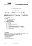
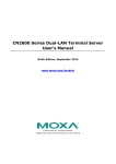
Remote Dial-in and Multi-Point Routing
Before we talk about what “Remote Dial-in” is, we recommend you to see the
Figure 1-1 to confirm whether the architecture is what you need. If so, Moxa
CN2100 Async Server provides remote dial-in access for not only those ISPs who
make people easy to use Internet resources via dial-in at home, but also all small
remote offices need this kind of solution to process the data in home office.
When you are sure this application is fit for your need, you also have to know how
PPP, SLIP, or Terminal works. Those protocols make “Remote Dial-in” function
of Moxa CN2100 Async Server work. Please refer to Chapter 5 for PPP / SLIP,
and Chapter 6 for Terminal settings.
Moxa CN2100 Async Server also provides static routing if you are considering to
setup an async router and the data is routed from LAN to LAN. The detailed
description and settings is also in Chapter 5.
Introduction 1-1
TCP/IP
Router
E-mail/News
Server
Web/FTP
Server
Moxa Async Server
Internet
RS-232
Notebook
Moxa
Async Server
PC
PC
Notebook
Modem
PC
Router
PC
PC
Figure 1-1
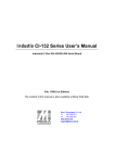
Terminal Access
If you are main-frame-based computing, you must use many terminals to access
the data in central system like Figure 1-2. Of course cashiers in Point-Of-Sale
system, terminals in stock exchange offices or travel agencies, to ATM machines
in banking system can use the reliable solution provided by Moxa CN2100 Async
Server. In this kind of application, Telnet protocol is necessary to be offered. Since
the architecture is what you want, we recommend you to refer to Chapter 4 for
the relevant settings and detailed description of “Terminal operation mode”. You
do need it.
TCP/IP
Windows NT
Moxa Async Server
RS-232
UNIX
Terminal
Terminal
Terminal
Terminal
Figure 1-2
1-2 Async Server User’s Manual
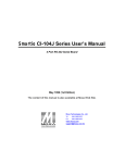
Reverse Telnet
You must be wondering how come Moxa CN2100 Async Server offers such a
function “Reverse Telnet”, and what “Reverse Telnet” is. Now we call “Reverse
Telnet” by “Rtelnet” by short and show you how it works briefly. “Rtelnet”
protocol provides TCP/IP network hosts or workstations with access to RS-232
devices connected to a terminal server. And Moxa CN2100 Async Server is the
one. That will help network administrators an alternative to manage other servers
or routers with console ports or the equipment with asynchronous interfaces but
without network controllers attached to Moxa CN2100 Async Server easily
through LAN. The Figure 1-3 is the simple prototype diagram. If you happened to
be this kind of user, you’d better refer to Chapter 9 for the relevant settings and
detailed description of “Reverse Telnet operation mode”. That’s really a
convenient way.
TCP/IP
Windows NT
Moxa Async Server
RS-232
UNIX
Server
Server
Router
Figure 1-3
Async Device Control over TCP/IP
Most telecommuters or industrial control have to deal with serial communication
data over TCP/IP networking for the trends of network. To program for data
access over serial transmission maybe easy, but to program serial data
transmission over TCP/IP maybe not.
To reduce the complexity of programming over TCP/IP, Moxa CN2100 Async
Server provides ASPP protocol on various network hosts. With ASPP protocol,
hosts can control devices attached to the Moxa CN2100 Async Server anywhere
on the network as if they are connected directly. Figure 1-4 shows you the
connection with different platform. In case you are the same as the one we talked
about, please refer to Chapter 7 for the relevant settings, usage and its detailed
description of “ASPP operation mode”. You will know the easy function calls
Moxa offered and the simple example program.
Introduction 1-3
In addition to ASPP, Moxa offers another method, RAW operation, for those who
would like to implement the program over TCP/IP individually, too. You can also
see the application diagram, Figure 1-4, and refer to Chapter 10 for the relevant
settings, usage and its detailed description of “RAW operation mode” if you need
this function.
TCP/IP
Windows NT
RS-232
POS
UNIX
Code Reader
Moxa Async Server
Equipment
Switch
Router
Internet
Modem
Router
Windows NT
SUN Workstation
Figure 1-4
Moreover, for the booming Windows NT users, Moxa offers the Windows NT
COM port driver that makes you control Moxa CN2100 Async Server’s async
ports as Windows NT’s standard COM ports. Of course you can run application
software like modem pooling, fax pooling, data acquisition, thin-client and RAS to
control those serial devices attached to Moxa CN2100 Async Server from any
Windows NT hosts on the network. Please find the URL
http://www.moxa.com.tw/support/download/download.php3 and
http://www.moxa.com.tw/support/documentation/documentation.php3 to get the
software Windows NT COM port driver, and its manual.
UNIX Fixed TTY application is also supported for serial access in UNIX systems
to interoperate with existing third party application software. Please refer to
Appendix F for the detailed descriptions. The Figure 1-4 may inspire you to
knowing your architecture better.
1-4 Async Server User’s Manual
1.2 Checklist
Upon unpacking the CN2100 Async Server, you should find the following items
included in your package:
n
CN2100 Async Server
n
AC power cord
n
Software diskette(It’s a UNIX tar format disk with some useful utilities
we’ve ever talked about in the previous section.)
n
This User’s Manual
n
RJ45 to female DB25 RS-232 cable (CN20030)
n
RJ45 to male DB25 RS-232 cable (CN20040)
n
Rackmount kit (2 brackets, 8 screws)
1.3 System Description
The CN2100 is equipped with a powerful 32-bit RISC-based microprocessor
(i960CA) and an RISC-based Ethernet controller. Its ROM contains firmware for
performing basic selftest and loading operated system program.
The operated system program, which is originally stored in the 512KB nonvolatile
Flash ROM, can be upgraded via software. This makes upgrade task much easier
because no hardware ROM chips need to be replaced. The configuration
parameters are also kept in the Flash ROM as well.
One important part of the operated system program is the CONSOLE utility. You
can access the windows-like CONSOLE utility from console ports or any network
host to configure and administrate the CN2100.
1.4 Features
The following is a summary of the features of CN2100:
Hardware
l
32-bit CPU Processor
l
1MB RAM
l
Easy firmware upgrade via 512K Flash ROM
l
TI550C UART
l
Auto-sensing Ethernet BNC 10Base2 and UTP RJ45 10BaseT connector
l
8 or 16 RJ45 RS-232 async ports with baud rate up to 921.6K bps
l
DTR, DSR, DCD, RTS, CTS, TXD, RXD, and GND port signals
Introduction 1-5
l
One RS-232 console port and one centronic Parallel port
l
Surge protection by Moxa A60 Surge protector (Optional)
l
Internal Auto-sensing 90~260V, 47~63Hz, 60W Power
Software
l
Friendly window-like administrative CONSOLE utility
l
Password protection and extensive user accounting
l
RAW function for transparent data transmission
l
Reverse Telnet function
l
ASCII/Binary terminal modes with four/one Telnet and Rlogin sessions
l
Dynamic auto-recognition of Terminal, SLIPD or PPPD
l
Point to point Protocol (PPP)
l
Serial Line Internet Protocols (SLIP and CSLIP)
l
Remote serial or parallel (RLP) printing
l
Async Server Proprietary Protocol (ASPP) for hosts to control the serial
devices connected to CN2100.
l
SNMP Agent for network management.
l
Domain Name Service (DNS).
l
Protocols: TCP/IP, ARP, UDP, ICMP, RCP, and Static Routing
l
Security protocols: RADIUS, PAP/CHAP, Dial-Back, and
Server password.
1-6 Async Server User’s Manual
1.5 Outlook
Front Panel-Figure 1-1 shows the front panel of the 16-port CN2100(CN2116);
Figure 1-2 shows the front panel of the 8-por CN2100(CN2108);
Figure
Figure
The CN2100 provides 16 or 8 RJ-45 async ports. Please refer to the Appendix B
for pin assignment and cable wiring. You may order Moxa if you need extra
cables.
Table 1-1 describes the indicators on the front panel.
LED
Color
Description
S0
Red
On when the AC power is on and CN2100 is ready
S1
Yellow
Used for special function, for example, CN2100
would be fleshing when Windows NT real COM
port driver was driven normally and you’d like to
locate CN2100. Otherwise, it would be on when
system abnormalizes
Tx
Red
Blinking when data being transmitted to the
Ethernet interface
Rx
Red
Blinking when data being received from the
Ethernet interface
Introduction 1-7
Figure 1-3 shows the rear panel of the CN2100.Async Ports
Figure 1-3
Console Port
The RJ-45 console port provides access to the CN2100 CONSOLE utility. Please
refer to Appendix B for pin assignment and cable wiring.
Network Interface
The CN2100 has the ability of auto-sensing two network interface ports
connecting to LAN:
.
l
10Base2 Ethernet port with a BNC connector
l
10BaseT Ethernet port with a RJ45 connector
Note: only one interface can be used at a time.
Printer Port
The CN2100 supports one parallel Centronics printer port with 25-pin female
connector.
Power Switch
The power switch allows you to disconnect AC power without disconnecting
power cord.
Power Selector
The CN2100 automatically selects the operational voltage range. It supports 90
to 260V, 47-63Hz AC power.
1-8 Async Server User’s Manual
2
Installation
There are several steps to follow before getting the CN2100 to work. The
instructions suppose that you have had a minimal TCP/IP network already.
2.1Attaching to the network
To connect to a 10Base2 Ethernet, you need to attach a BNC T-connector from the
Ethernet cable to the CN2100. If CN2100 is on the termination point of the
Ethernet cable, you need a terminator on the T-connector also.
To connect a 10BaseT Ethernet, insert the RJ45 network plug into the RJ45
connector on the CN2100.
After connecting the hardware to your network and your subnet is also in
192.168.127.xxx, you can directly use telnet program to CN2100’s IP address for
console utility working like described in Chapter 3. The default value of Async
Server IP is 192.168.127.254. If your subnet is different from 192.168.127.xxx,
you may add routing in your computer or follow the procedures described in the
next section to attach a console terminal.
.
Note:
1.If 10Base2 is used, the 10BaseT connection must be removed. CN2100
supports auto-sensing network connector. When both kind of network
connectors are attached at the time of power on , the console program by
telnet doesn’t work. You have to remove the unused connection, turn off
and on your CN2100 power switch, then the console program by telnet
can work properly.
2.You may add one routing, like “route add 192.168.127.254” in Windows
95/98/NT system’s DOS mode, then use ping command, “ping
192.168.127.254” to confirm if this routing work or not. If you
Installation 2-1
successfully add this routing in your host, you can directly telnet the
CN2100’s IP address
2.2 Attaching console terminal
Another way to make console utility work is attaching a terminal (vt52 or
vt100/ansi) or a PC running terminal emulation to the RJ45 console port located
on rear panel using the shipped RJ45 to female DB25 RS-232 cable (refer to
Appendix B for its cable wiring). You need this terminal to make necessary
configuration if you can’t easily access the console utility via Ethernet.
.
Note: The terminal has to be set as 19200bps, 8 bits, no parity and 1 stop bit.
2.3 Power-up
All we talk about in the previous sections will be done successfully after you
install the power cord and switch the power on. The CN2100 now runs its ROMresident diagnose. The indicator lights are off in this stage, except for the power
indicator S0.
2.4 Running the system program
The CN2100 will then automatically download the operated system program from
the Flash ROM and run it.
2-2 Async Server User’s Manual
3
Configuration
Configuring the CN2100 involves setting parameters to define the unit’s necessary
operating and administrative attributes. These attributes included:
¨
Defining IP address for the CN2100
¨
Selecting the network interface, 10Base2 or 10Base T
¨
Setting up security / password
¨
Defining the IP address reference table for the preferred hosts
¨
Setting up the PPP/SLIP routing table
¨
Editing the hello message for terminal users
¨
Defining the operation mode of each async port
¨
Customizing the CN2100 environment
To do the configuration, you must access to the CONSOLE utility in any one of
the following ways:
From a terminal with (Speed 19200, Parity None, Data bit 8, Stop bit 1)
connected to the console port at the rear panel ;
From a network host, Telnet the CN2100’s IP address (the default value is
192.168.127.254) if your subnet ‘s IP is in the 192.168.127.x. Otherwise you have
to add a routing to your host. Please note the procedure for routing added is
different in each platform.
Configuration 3-1
.
Note:You may add one routing, like “route add 192.168.127.254” in Windows
95/98/NT system’s DOS mode, then use ping command, “ping 192.168.127.254”
to confirm if this routing work or not. If you successfully add this routing in your
host, you can directly telnet the CN2100’s IP address.
Figure 3-1
.
Note: Only one CONSOLE session can be activated at a time. The first prompt
by telnet /console port will be showing as the figure above.
It is important that the terminal or PC running terminal emulation (HyperTerminal
of Windows 95/98/NT, PC-PLUS, Telix, etc.) must be one of the types listed
above; otherwise the cursor movement and display might not work as expected.
Enter the console password and then select the terminal type if required. You can
find HyperTerminal application at [Start] | [Programs] | [Accessories] |
[Communications] | [Hyperterminal] | [HyperTerminal] in Windows 95/98 or at
[Start] | [Programs] | [Accessories] | [Hyperterminal] | [HyperTerminal] in
Windows NT. When you use HyperTerminal, please remember to set the port
Speed at 19200, Parity None, Data bit 8, and Stop
bit 1.
3-2 Async Server User’s Manual
3.1 Window-like CONSOLE
The CN2100 provides a window-like CONSOLE utility. The utility is designed in
such a way to provide easier and friendly human interface for configuration and
administration. A handy on-line help is accessible almost anywhere during the
configuration procedure. You can always hit F1 or Ctrl-R to bring the help
message.
To give user an idea about the window-like utility, the figures 3-2, 3-3 show a
typical menu, You can use arrow key or initial letter of each function to choose the
desired function. For example, you will see the firmware version of Moxa
CN2100, V1.xx, at the top of the menu first of all. Then you can move cursor to
other function in figure 3-3 by press ”H” for “Host”, “L” for “Line”, for example,
or locate cursor at [Server] position and hit “Enter” to configure server
information.
Configuration 3-3
The type of
MENU you
are under now.
Available
function under
Configure
menu.
Figure 3-2
Now you
are under
Configure
menu.
Figure 3-3
After the configuration is completed, please make sure to save it first. Then restart
the CN2100 to take effect the configuration. Otherwise all your modifications will
3-4 Async Server User’s Manual
be lost when CN2100’s switch is turned off. Of course you can immediately
restart your system after modifying the parameters for a temporary test.
3.2 Server
After hitting <Enter> key to select the [Server] function, you may start
configuring the CN2100 server information like below.
Figure 3-4
The following message is the detailed description for each element under [Server].
Async Server name -This field contains the name of this Async Server. The
Async Server identifies itself by this name when SNMP station or UNIX host
requests. The name should be an ASCII string with length no more than 30
characters. Blank is allowed.
Async Server location-This field contains the location of this Async Server. The
Async Server will report this location to SNMP station by request. The name
should be an ASCII string with length no more than 40 characters. Blank is
allowed.
Configuration 3-5
Async Server IP address-This field MUST contain a unique Internet Protocol (IP)
address in the network. The IP address appears in a dotted notation as
ddd.ddd.ddd.ddd. Each 'ddd' is a decimal number. The default value is
192.168.127.254.
Async Server IP netmask-This field contains the server ethernet IP network
mask pattern. 'Blank' means the network mask depends on IP address classes. For
example, if the IP address is 192.168.127.254, belonging to class C (Please refer
to Appendix C), the network mask is ought to set as 255.255.255.0. More detail
information, please ask your network administrator of help.
RADIUS server IP-RADIUS is for short of Remote Authentication Dial-In User
Service, used for authentication of remote dial-in users in any ISPs (Internet
Service Providers). If you don’t have a RADIUS server on your network, you can
skip this field. Since the Async Server is a diskless device, it is hard for the Async
Server to hold all the important authentication data such as RADIUS information.
To solve this problem, users can specify a network host that has hard disk as the
RADIUS server. With MOXA-supplied software, the RADIUS server can
cooperate with the Async Server to do the authentication check and to record the
user's activity.
This field contains the IP address of the RADIUS server. If you are setting up a
network host as the RADIUS server, then this field must be filled. MOXA
provides the necessary software, at the enclosed software diskette, to function the
security and accounting task on UNIX-based platform. Please also refer to the
\radius.2.2\read.me file after uncompressed this radius.2.2.tar.z for more
information.
.
Note: The RADIUS server and Async Server SHOULD be able to
communicate with each other, for example, they ping successfully on each other.
RADIUS key- RADIUS key is a shared key for RADIUS protocol. If you get a
RADIUS server, you would have to create a password here.
UDP port (1:1645 2:1812)-There are two choices for port numbers for RADIUS
UDP port number. The early deployment of RADIUS was done using the
erroneously chosen port number 1645, which later conflicts with the RFC standard.
The officially assigned port number for RADIUS is 1812. That means the UDP
port number for the newer RADIUS server software is 1812. But we recommend
that 1645 is the first choice. Many companies in industry still adopt 1645 as UDP
port number in RADIUS server. You can check UDP port number in your
RADIUS server software while making the choice. Moreover, the UDP port
3-6 Async Server User’s Manual
number of Moxa RADIUS Server utility is fixed at 1645.
Enable RADIUS accounting -This field will set as “yes” as default. If your
RADIUS Server didn’t offer this kind of function, please set it as “No”.
Domain server IP address-This field specifies the IP address of the Domain
Name Server. If you use domain name, like “www.moxa.com.tw” in any kind of
application, we strongly recommend you to specify your Domain Name Server IP
on your LAN here.
SNMP community name-The SNMP community name is a way to guarantee
minimal security for SNMP communication. Only the SNMP stations with the
same community name can access to the SNMP agents like Async Server. Enter
the community name with no more than 16 ASCII characters. The default name is
'public'.
SNMP trap server IP address-This field specifies the IP address of the SNMP
trap server. The Async Server will report to the SNMP trap server each time when
it restarts the unit. You may skip this if no SNMP is needed
Ethernet cable type -The interface is set as “Auto” as default. Because CN2100
will auto-sense your ethernet cable type when you turn it on. If you are certain
about your connection, please select the specific one to save system starting time.
Ethernet address-This field contains the hardware Ethernet address. Modification
of this field is not allowed.
Console password- You may or may not specify the password for the CONSOLE
utility. If you specified the password, you would need to enter the password before
getting into the CONSOLE utility. The console password is strongly
recommended to highly keep in mind or write down in your note. If you
accidentally lose it, you can only contact Moxa Technical Support for help.
.
Note: Save your console password in a safe place as soon as you set the
password.
Configuration 3-7
3.3 Host
The host table is designed for editing the frequently referred host names and their
corresponding IP addresses. The advantage is that you can easily refer to a host by
its name instead of the cumbersome IP address. The host table can hold up to 16
[Host name]-[Host IP address] entries as seen in the Figure 3-5.
Figure 3-5
The following message is the detail description for each element under [Host].
Host name -This field contains the memorizable name of a host.
Host IP address-This field specifies the IP address of the host.
3-8 Async Server User’s Manual
3.4 Line
The Figure 3-6 is about each async Line's configuration such as baud rate, parity
and flow control condition.
Figure 3-6
The following message is the detailed description for each element under [Line].
Speed-Specify the baud rate of the async line. Press Enter to list the available
speeds (50-921.6K) and make a choice.
Bits-Specify the data bits of the async line. Press Enter to list the available data
bits (5-8) and make a choice.
Stop-Specify the stop bits of the async line. Press Enter to list the available stop
bits (1, 1.5, 2) and make a choice.
Configuration 3-9
Parity-Specify the parity of the async line. Press Enter to list the available parity
type (none, odd, even) and make a choice.
TxFIFO -Enable the FIFO of async line. Default is yes. You can change it as ‘No’
upon your request.
RTS/CTS-Specify if you wish to apply hardware flow control over the async line.
If 'yes', then the RTS and CTS control signals must be included in the cable wiring.
The other end, e.g. terminal, should enable RTS/CTS flow control as well.
RTS/CTS flow control is always recommended in order to prevent possible data
loss.
XON/XOFF-Specify if you wish to apply software flow control over the async
line. If 'yes', then the other end, terminal for example, should also enable
XON/XOFF flow control.
.
Note: If the async line is configured as a PPP, SLIP or TERM_BIN mode, then
the XON/XOFF flow control must be set to 'no'. Otherwise the XON or XOFF
control code may interfere the communication.
Discon.Ctrl-Specify the line disconnection condition. If 'DCD-off' selected, the
line will be automatically disconnected when DCD signal goes off.
3-10 Async Server User’s Manual
3.5 OP_mode
Figure 3-7 shows you port operation modes that CN2100 offered. For the detailed
settings in different operation modes, you may see Chapter 4 to Chapter 10 for
your reference. Be aware that all ports on CN2100 can be set to different
OP_mode.
Figure 3-7
Configuration 3-11
3.6 Route
Figure 3-8 shows the routing table CN2100 supported.
Figure 3-8
The following message is the detailed description for each element under [Route].
Gateway-This field specifies the gateway IP address or the interface source IP
address which data packets should be sent to.
Destination-This field specifies the IP address of a host or network for which the
route is going to.
Netmask-This field specifies the mask pattern of the destination network.
Metric-This field indicates the number of hops from source to the destination.
3-12 Async Server User’s Manual
3.7 Parameters
All configurations that are modified must be save in [Parameters]. Otherwise you
will lose the settings you’ve ever made once CN2100 is off. Now enter the
parameters menu to save your configurations like Figure 3-9.
Figure 3-9
CN2100 also offers the way to save your configurations to a file in a disk by
[Upload] . You may also retrieve the settings from a file by selecting [Download]
to CN2100. For detailed description, please see Chapter 11.5 for your reference.
Configuration 3-13
3.8 Restart
If you finish all settings in the previous sections, you have to restart your system
to make configurations take effect! Since restarting system will disconnect current
communications, system will show you the warning message to confirm your
decision.
Figure 3-10
So far you’ve finished the basic settings of CN2100.
3-14 Async Server User’s Manual
4
Terminal Mode Operations
Users can hook up terminals to the CN2100 aysnc ports then login to any TCP/IP
host in the network via telnet or rlogin protocol. In this case, the CN2100 acts as a
terminal server. This chapter describes the terminal modes that CN2100 supports:
ASCII terminal mode and Binary terminal mode.
4.1 ASCII terminal mode
For all charters control, you may select ASCII terminal mode. Each async port
with ASCII terminal mode (TERM_ASCII) supports four independent terminal
sessions. You can switch among these sessions by pressing the pre-defined hot key.
If the [Configure][Hello] is enabled, the greeting message will be displayed
automatically each time your terminal connects to the CN2100.
The following figure and description shows the detailed settings of
“TERM_ASCII”.
Terminal Mode Operations
4-1
Figure 4-1
The following message is the detailed description of each element for
[TERM_ASC].
Session-Each terminal connected to a port with ASCII terminal mode will
virtually have 4 sessions. This field defines the hot-key to switch to the next
session in sequence. The default hot-key is a composite key of Ctrl (^) and ‘T’
character.
Quit-This field defines the Quit key used to disconnect the link between the
current terminal session & the remote host. The default key is a composite key of
Ctrl (^) and ‘E’ character.
Erase-line-This field defines the erase-line key. When this key is typed, a telnet
'EL' command will be sent to the remote host. There is no default erase-line key.
Erase-character-This field defines the erase-character key. When this key is typed,
a telnet 'EC' command will be sent to the remote host. There is no default erasecharacter key.
4-2 Async Server User’s Manual
Break-This field defines the break key. If this key is typed, the telnet BREAK
signal will be sent to the remote host. There is no default break key.
Interrupt-This interrupt key is used to interrupt the remote process within a
connection. It attempts to cause an immediate termination of the current process
like Ctrl-C does on a local terminal.
Auto-link protocol-This field specifies the type to connect to a host automatically.
Press Enter to choose Telnet or Rlogin protocol. If set to 'none', then users have to
choose the protocol themselves when making a connection
Telnet TCP Port- This field specifies the TCP port which will be used to attach to
a network host. Default TCP port number is 23.
Primary host IP-This field, if specified, designates a 'permanent' host to which
the terminal will always be connected. Enter the host’s IP address, the host’s name
defined in the [Host] table, or the host’s name defined in domain name server.
Secondary host IP-This field, if specified, designates a secondary host to be
connected when the terminal fails to connect the primary host. Enter the host's IP
address or the host’s name defined in domain name server.
Auto-login prompt-This field designates the keyword for checking the login
prompt before send out the user name while the auto-login function is activated ,If
you erase this prompt to blank, the auto-login function is disabled.
Password prompt-This field designates the keyword for checking the password
prompt before send out password. If you erase this prompt to blank, the autopassword login function is disabled.
Login user name-This field designates the user name sent to connected host for
auto-login. If this field is a blank, the auto-login function is disabled.
Login password-This field designates the password sent to the connected host. If
this field is a blank, the password has to be hit when connected to host.
Terminal Mode Operations
4-3
Terminal type-The terminal type is sent to the remote host after the user logs into
network host successfully. This is available as the TERM environment variable.
Inactivity time -The terminal session will be disconnected after 'Time-out' minutes
of inactivity. Press Enter to list the available time-out time. 0m means no time-out
restriction.
Authentication type-The Async Server offers three types of security check when
a user make a connection to it before go to network hosts:
'none' -
No security check. Every user can freely access to the Async Server
via this port.
'local' -
Security check based on this port's local password specified at next
field, "Local password". User must supply the correct password of
the port before he can access to the Async Server.
'server' -
Security check based on the security data base maintained on the
RADIUS server described on [Configure][Server] menu. When a user
wish to access to the Async Server via this port, he is requested to
supply user name and password; the Async Server will then check
with the RADIUS server to validate the supplied user name and
password. To accomplish this, the 'RADIUS server IP' address on
[Configure][Server] menu must be correctly specified. Also, running a
security software on the RADIUS server is necessary.
Local password-The access password of this port. This password is only valid
when the 'Authentication type' is set to 'local'. Enter the ASCII text password with
size up to 16 bytes.
TCP alive check time -Specify the time slice for checking whether TCP
connection still established. 1-99 minutes can be set. If there is no response from
the connected host in the time you specified, CN2100 will reset this port. The
original connection will be disconnected.
4-4 Async Server User’s Manual
4.2 Binary terminal mode
The reason for naming Binary terminal mode is because the port operation will
keep transparent transmission of data from 0x00 to 0xFF. That is, the port will not
interface any single byte coming in and out, and no data for control key will be
ruled out except Quit key. This mode is suitable for those applications that need
protocol transmission. For example, file transfer with XMODEM or ZMODEM,
etc. Thus, the mode supports only one terminal session.
If the [Configure][Hello] is enabled, the greeting message will be displayed
automatically each time your terminal connects to the CN2100. The following
figure and description shows the detailed settings of “TERM_BIN”.
Figure 4-2
The following message is the detail description of each element for [TERM_BIN].
Terminal Mode Operations
4-5
Quit key-This field defines the Quit key used to disconnect the link between
current terminal session and remote host. The default key is a composite key of
Ctrl (^) and E character.
Auto-link protocol-This field specifies the type to connect to a host automatically.
Press Enter to choose Telnet or Rlogin protocol. If set to 'none', then users have to
choose the protocol themselves when making a connection.
Telnet TCP Port- This field specifies the TCP port which will be used to attach to
a network host. The default TCP port number is 23.
Primary host IP-This field, if specified, designates a 'permanent' host to which
the terminal will always be connected. Enter the host's IP address, the host’s name
defined in the [Host] table, or the host’s name defined in domain name server.
Secondary host IP-This field, if specified, designates a secondary host to be
connected when the terminal fails to connect the primary host. Enter the host's IP
address or the host’s name defined in domain name server.
Auto-login prompt-This field designates the keyword for checking the login
prompt before send out the user name while the auto-login function is activated If
you erase this prompt to blank, the auto-login function is disabled.
Password prompt-This field designates the keyword for checking the password
prompt before send out password. If you erase this prompt to blank, the autopassword login function is disabled.
Login user name-This field designates the user name sent to connected host for
auto-login. If this field is a blank, the auto-login function is disabled.
Login password-This field designates the password sent to the connected host. If
this field is a blank, the password has to be hit when connected to host.
4-6 Async Server User’s Manual
Terminal type-The terminal type is sent to the remote host after the user logs into
network host successfully. This is available as the TERM environment variable.
Inactivity time -The terminal session will be disconnected after 'Time-out' minutes
of inactivity. Press Enter to list the available time-out time. 0m means no time-out
restriction.
Authentication type-The Async Server offers three types of security check when
a user make a connection to it before go to network hosts:
'none' -
No security check. Every user can freely access to the Async Server
via this port.
'local' -
Security check based on this port's local password specified at next
field, "Local password". User must supply the correct password of
the port before he can access to the Async Server.
'server' -
Security check based on the security data base maintained on the
RADIUS server described on [Configure][Server] menu. When a user
wish to access to the Async Server via this port, he is requested to
supply user name and password; the Async Server will then check
with the RADIUS server to validate the supplied user name and
password. To accomplish this, the 'RADIUS server IP' address on
[Configure][Server] menu must be correctly specified. Also, running a
security software on the RADIUS server is necessary.
Local password-The access password of this port. This password is only valid
when the 'Authentication type' is set to 'local'. Enter the ASCII text password with
size up to 16 bytes.
TCP alive check time -Specify the time slice for checking whether TCP
connection still established. 1-99 minutes can be set. If there is no response from
the connected host in the time you specified, CN2100 will reset this port. The
original connection will be disconnected.
Terminal Mode Operations
4-7
5
PPP and SLIP Operations
This chapter describes the CN2100’s implementation for transmitting data over
serial point-to-point links, Point-to-Point Protocol (PPP) and Serial Line Internet
Protocol (SLIP).
In case your application happened to be the same as Figure 1-1 for Remote Dialin or Multi-Point Routing, like what we talked in Chapter 1, PPP and SLIP are
the right operation modes you have to specify on those async ports in Moxa
CN2100 Async Server.
5.1 Point-to-Point Protocol (PPP)
PPP, the most popular protocols used in today’s Internet connection, enables you
to send datagrams across a serial line or telephone data circuits. PPP’s features
lists as below:
¨
Built-in error detection of transmission data.
¨
Dynamic connects and disconnects service to reduce phone line costs
during inactive time.
¨
Security check (Password Authentication Protocol, PAP)
Connecting two networks via a PPP link
Using the PPP link, you can connect a host to the network without requiring
special hardware, or multiplex data between two distant networks. The following
information shows a way of routing traffic from any node on network
132.147.10.0 to any node on network 132.147.160.0 via PPP link constructed in
Figure 5-1. To realize this, the routing table of each network node ought to look
like:
PPP and SLIP Operations
5-1
Host 1
Gateway
Destination
Netmask
Metric
132.147.160.10
132.147.10.0
255.255.255.0
2
Gateway
Destination
Netmask
Metric
132.147.5.2
132.147.10.0
255.255.255.0
2
CN2100
.
Note: You must enter the routing entry into the CN2100 [Route] section in
[Configure] menu manually.
Host 2
Gateway
Destination
132.147.10.8 132.147.160.0
Netmask
255.255.255.0
Metric
2
Host 3
Gateway
Destination
Netmask
Metric
132.147.5.1
132.147.5.2
255.255.255.255 1
132.147.5.2
132.147.160.0
255.255.255.0
2
At [Configure] | [OP_mode], the PPP mode means a leased line connection; while
the PPPD (PPP Daemon) mode stands for dial in / dial out active connection link.
The following figure shows detailed settings for PPP. Note that PPP and PPPD
have the same settings. Furthermore, specified Source IP address in [Configure] |
[OP_mode] | [Description/more setting] can be used as CN2100’s gateway to
Destination 132.147.10.0 via PPP link in this example.
Network 132.147.160.0
Host1
CN2100
TCP/IP
132.147.160.10
132.147.160.1
132.147.5.2
PPP Link
Host2
Host3
132.147.10.7
132.147.10.8
Network 132.147.10.0
Figure 5-1
5-2 Async Server User’s Manual
132.147.5.1
TCP/IP
The detailed settings of PPP, please see Figure 5-2.
Figure 5-2
The following message is the detail description of each element for [PPP].
Destination IP addr-'Blank' or '0.0.0.0' means the IP is assigned by remote site. If
other IP specified, the remote site must use the IP address.
Source IP address-You must specify the IP address of the local site in this field.
'Blank' means the source IP address is the server's IP address.
IP netmask-This field contain the PPP Destination IP network mask pattern.
'Blank' means the network mask is 255.255.255.255, and Dial-in users are
recommended to left this field blank.
PPP and SLIP Operations
5-3
TCP/IP Compression-If this field is set to 'yes', then the Van Jacobson
Compressed TCP/IP Protocol is negotiated. Otherwise normal PPP is applied.
Inactivity time -The PPP link will be disconnected after specified minutes of
inactivity. Press Enter to list the available time-out time. 0m means no time-out
restriction.
Link quality report-Configure the setting of negotiation of Link Quality
Monitoring protocol (RFC 1333). It is usually used for the administrator to figure
out the current status of link quality. You may use the relevant application to
collect it. ‘yes’ is to negotiate.
Outgoing PAP ID-If this and next fields are specified, the Password
Authentication Protocol will be used. The Async Server will send this PAP ID to
the remote site for validation when the remote site requests.
PAP password-The Async Server will send this PAP password to the remote site
for validation when the remote site requests.
Incoming PAP check-The Async Server offers three types of security check when
an user would like to make a PPP connection to it:
'none' -
No security check. Every user can freely access to the Async Server
via this port.
'local' -
Security check based on this port's local password specified at next
field, "Local password". User must supply the correct password of
the port before he can access to the Async Server.
'server' -
Security check based on the security data base maintained on the
RADIUS server described on [Configure][Server] menu. When a
user wish to access to the Async Server via this port, he is requested
to supply user name and password; the Async Server will then
check with the RADIUS server to validate the supplied user name
and password. To accomplish this, the 'RADIUS server IP' address
on [Configure][Server] menu must be correctly specified. Also,
running a security software on the RADIUS server is necessary.
5-4 Async Server User’s Manual
Local password-The access password of this port. This password is only valid
when the 'Authentication type' is set to 'local'. Enter the ASCII text password with
size up to 16 bytes.
.
Note:
1. PPP-The PPP mode settings is basically the same as PPP mode except it only
supports dial-in line.
2. If an async port is set to PPP/PPPD mode, the line configuration on
[Configure][Line] menu should be set to 8 data-bits, no-parity, 1 stop-bit.
PPP and SLIP Operations
5-5
5.2 Serial Line Internet Protocol (SLIP)
The CN2100 supports Serial Line Internet Protocol (SLIP) which makes you send
TCP/IP packets through a serial line or telephone data circuits. A SLIP link is a
point-to point connection between two hosts. Using the SLIP link, you can
connect a host to the network without requiring special hardware, or multiplex
data between two distant networks. The CN2100 also supports Compressed SLIP
(CSLIP).
The following lists the options for setting up a SLIP link:
l
You can attach a host to a CN2100 async port. Using the SLIP as the
network interface, the host becomes a node on the network.
l
You can use SLIP to connect two separate networks, routing data from one
network to the other over the SLIP link.
For best performance, you’d better set the line speed to as high as possible when
using a SLIP link for retrieving files from a host.
Compressed SLIP
The Compressed SLIP compresses the TCP/IP headers of SLIP protocol from 40
bytes to as few as three bytes and hence the name. This technique improves the
overall throughput because of smaller packets.
SLIP Configuration
When setting up the CN2100 SLIP link, some rules must be followed:
l
Since the SLIP is an 8-bit protocol, the async port should be set as 8 data
bits, 1 stop bit and no parity. The XON/XOFF control must be disabled
as well.
l
For leased line (if the async port’s (OP_mode) is set to SLIP), you must
specify IP addresses of both ends of the SLIP link.
l
For dial in line (if the async port’s (OP-mode) is set to SLIPD), the local
site’s IP address must be specified while the remote site’s may be UNspecified. If the remote site’s IP is not assigned, the CN2100 will autolearn the remote IP addr. Figure 5-3 shows the detailed settings for SLIP.
SLIP and SLIPD have the same settings.
5-6 Async Server User’s Manual
Figure 5-3
The following message is the detailed description of each element for [SLIP].
Destination IP addr-'Blank' or '0.0.0.0' means the IP is assigned by remote site. If
other IP specified, the remote site must use the IP address.
Source IP address-You must specify the IP address of the local site in this field.
'Blank' means the source IP address is the server's IP address.
PPP and SLIP Operations
5-7
IP netmask -This field contains the SLIP Destination IP network mask pattern.
'Blank' means the network mask is 255.255.255.255, and Dial-in users are
recommended to left this field blank..
TCP/IP Compression-If this field is set to 'yes', then the Compressed Serial Line
Internet Protocol (CSLIP) is used. Otherwise normal SLIP is applied.
Inactivity time -The DTR output will be dropped off after specified minutes of
inactivity. Press Enter to list the available time-out time. 0m means no time-out
restriction.
.
Note:
1. SLIPD-The SLIPD mode is basically the same as SLIP except it only supports
dial-in line.
2. If an async port is set to SLIP/SLIPD mode, the line configuration on
[Configure][Line] menu should be set to 8 data-bits, no-parity, 1 stop-bit.
Connecting a Single Host with a SLIP link
The connected host with a SLIP link appears as a node on the network. Specify a
unique IP address to that host. See Figure 5-4 and the following descriptions.
TCP/IP
132.147.160.10
CN2100
132.147.160.1
132.147.100.2
132.147.100.3
Host1
SLIP Link
Workstation
Figure 5-4
5-8 Async Server User’s Manual
The routing table of each network node could look like:
Host 1
Gateway
Destination
Netmask
Metric
132.147.160.10
132.147.100.3
255.255.255.255 2
Destination
Netmask
Workstation
Gateway
Metric
132.147.100.3132.147.100.2
255.255.255.255 1
132.147.100.2132.147.160.0
255.255.255.0
2
CN2100
The below routing table is automatically generated by CN2100 when you finish
the settings in [Configure] | [OP_mode] |[SLIP] / [Description/more setting] like
Figure 5-3.
Gateway
Destination
132.147.100.2132.147.100.3
Netmask
Metric
255.255.255.255 1
PPP and SLIP Operations
5-9
6
Integrated Dynamic Operations
This chapter shows you how to process terminal, PPP, SLIP, the three functions at
a time. That’s an easy way by setting up OP_mode as a three in one [dynamic].
Dynamic function not only integrated the three functions, but also automatically
detected the connection belonging to which kind of mode.
Taking a look at the following figure. You just enable each function included in
[Dynamic], all the detailed settings is the same as we described previously. Please
note that the authentication type must be specified upon your request when you
use PPPD or TERM_BIN. Of course you can enable only one of those functions,
then it will not offer the other service.
Integrated Dynamic Operations 6-1
Figure 6-1
When you finished the settings, remember to save in [parameters], then restart
your system to take effect.
6-2 Async Server User’s Manual
7
Async Server Proprietary Protocol
The CN2100 Async Server supports a Proprietary Protocol (ASPP) that allows
application based on this protocol to control the devices connected to the CN2100.
The device could be a bar code reader, a POS terminal, data acquisition equipment,
a modem or any other serial device. To ease the ASPP implementation, a
command set and its associated subroutines on UNIX/Windows platform are
provided.
To use the function, the desired async ports must be set as ASPP mode on
[Configure] [OP_mode] menu as the figure below.
Async Server Proprietary Protocol 7-1
Figure 7-1
7.1 Basic Concepts
Each physical ASPP port is divided into two logical ports: one is called command
port, the other is called data port. Via command port, user can issue commands
across the network to set the line’s configuration such as baud rate, data bits, flow
control condition, etc. Via data port, user can retrieve data through the async line.
There is a unique TCP port number associated with each of the ASPP command
and data port. The TCP port number is defined as follows:
7-2 Async Server User’s Manual
Physical port no.
Command TCP port number
Data TCP port number
01
950
966
02
951
967
03
952
968
04
953
969
05
954
970
06
955
971
07
08
956
957
972
973
09
958
974
10
959
975
11
960
976
12
961
977
13
14
926
963
978
979
15
964
980
16
965
981
7.2 Programming the ASPP port
In the cnclosed CN2100 Software Diskette (UNIX tar format), you can find the
example program illustrating how to control the ASPP port successfully. There are
several basic subroutines included in \aspp\as.h after uncompressed ASPP.tar.z.
Since CN2100 belongs to CN2000 series, the programming utilities implemented
Async Server Proprietary Protocol 7-3
with CN2000 as below also fit for CN2100 users.
*************************************************************
Useful subroutines to control 'ASPP' port
1. sio_copen(ipaddr, p)
Open command port.
2. sio_dopen(ipaddr, p)
Open data port.
3. sio_reset(fd_cmd)
Reset a port.
4. sio_ioctl(fd_cmd, baud, mode)
Set port baud, parity, etc.
5. sio_flowctrl(fd_cmd, CTSmode, RTSmode, TxXon,
RxXon)Set hardware and/or software flow control.
6. sio_lctrl(fd_cmd, DTRon, RTSon)
Line control.
7. sio_flush(fd_cmd, mode)
Flush input/output buffer.
8. sio_lstatus(fd_cmd)
Check line status.
9. sio_iqueue(fd_cmd)
Check how many data in input buffer.
10.sio_oqueue(fd_cmd)
Check how many data still in output buffer.
****************************************************************
In general, to be able to control the devices attached to the ASPP port, you will
have to do the following procedures:
¨
Create a socket for command port and connect to it.
¨
Set the port configuration, e.g. baud, via command port.
¨
Create a socket for data port and connect to it.
¨
Transfer data via data port.
7-4 Async Server User’s Manual
Here is a piece of a Program Example that demonstrates how to control and ASPP
port and will continuously send '1234567890' string out from CN2100 RS-232
port, whose port Mode should be set as 'ASPP', and read back any incoming data
until program interrupted.
Setting:The target port will be configured as: no parity, 8 data bits, 1 stop bit, with
software(XON/XOFF) flow control, but no hardware(RTS/CTS). 1st port
and 9600bps is default, however you may change it in command line.
The target port Mode should be set as 'ASPP' via [Configure] [OP_mode]
from Async Server CONSOLE utility.
Syntax: # ./as AsyncServerName [port(1) [Baud(9600)]]
For example:
# ./as cn2100 1 19200
Then the program will send '1234567890' to port 1 on Async Server at 19200 bps
baud and read back any data on it.
Environment:This program is originally developed under SCO UNIX. Your
environment may be different, if so, the included file name and
other variable may need to be modified to suit your environment.
Async Server Proprietary Protocol 7-5
#include
<stdio.h>
#include
<fcntl.h>
#include
<sys/errno.h>
#include
<sys/socket.h>
#include
<netinet/in.h>
#include
<netdb.h>
#include
<arpa/telnet.h>
#include
"as.h"
int
fd_cmd, fd_data;
main(argc, argv)
int argc;
char *argv[];
{
int
fd, port, i, baud;
unsigned long
struct hostent
ipaddr;
*name;
struct sockaddr_in
des;
unsigned char
buf[100];
port = 1;
/* target port = 1st port on cn2000
*/
if(argc==1) {
printf("\nNo Async Server name specified.\n");
printf("\nSyntax: # ./as
[port(1)[Baud(9600)]]\n");
AsyncServer
printf("For example: # ./as
cn2000 1 9600\n\n");
exit(0);
}
memset(&des,0,sizeof(des));
printf("Hook up a terminal to the first port to test.\n");
name = gethostbyname(argv[1]);
if(!name) {
7-6 Async Server User’s Manual
printf("\n%s must appear in '/etc/hosts'.\n",argv[1]);
printf("Please add cn2000
IP addr and name into
/etc/hosts.\n");
exit(0);
}
strncpy((char *)&des.sin_addr, name->h_addr, name->h_length);
printf("CN2000 IP addr = 0x%X(%s) \n",des.sin_addr.s_addr,
inet_ntoa(des.sin_addr.s_addr) );
if (argc > 2)
port = atoi(argv[2]);
if(argc > 3){
baud = atoi(argv[3]);
switch(baud){
case 300:
baud = D_IOCTL_B300;
break;
case 600:
baud = D_IOCTL_B600;
break;
case 1200:
baud = D_IOCTL_B1200;
break;
case 2400:
baud = D_IOCTL_B2400;
break;
case 4800:
baud = D_IOCTL_B4800;
break;
case 9600:
baud = D_IOCTL_B9600;
break;
case 19200: baud = D_IOCTL_B19200;
break;
case 38400: baud = D_IOCTL_B38400;
break;
case 57600: baud = D_IOCTL_B57600;
break;
case 115200: baud = D_IOCTL_B115200;
break;
Async Server Proprietary Protocol 7-7
case 230400: baud = D_IOCTL_B230400;
break;
case 460800: baud = D_IOCTL_B460800;
break;
default :
printf("invalide baud rate %d \n",baud);
exit(0);
}
}
else
baud = D_IOCTL_B9600;
if (argc > 3)
printf("\nport %d : %s,n,8,1,no RTS/CTS flow control.\n\n",
port,argv[3]);
else
printf("\nport %d : 9600,n,8,1,no RTS/CTS flow
control.\n\n",port);
printf("Press any key to continue...\n"); i=getchar();
if((fd_cmd=sio_copen(des.sin_addr.s_addr,port))==FAIL){
printf("\nCommand port %d open fail.(port Mode may
wrong)\n",port);
printf("\nRe-examine the port Mode from cn2000 CONSOLE.\n");
exit(0);
}
else
printf("Command port %2d opened OK.(cmd=%d)\n",port,fd_cmd);
if( sio_reset(fd_cmd)==FAIL) {
printf("Port reset error.\n");
exit(0);
} else
printf("Port reset OK.\n");
7-8 Async Server User’s Manual
if( sio_ioctl(fd_cmd,baud,D_IOCTL_BIT8
+D_IOCTL_STOP1 + D_IOCTL_NONE)==FAIL) {
printf("Port ioctl error.\n");
exit(0);
} else
printf("Port ioctl OK. \n");
if( sio_flowctrl(fd_cmd, D_FCTRL_CTS_NO, D_FCTRL_RTS_NO,
D_FCTRL_TXXON_YES, D_FCTRL_RXXON_YES)==FAIL) {
printf("Port flow control error.\n");
exit(0);
} else
printf("Port flow control OK.\n");
if( sio_flush(fd_cmd, D_FLUSH_ALLBUFFER)==FAIL) {
printf("Port flush error.\n");
exit(0);
} else
printf("Port flush OK.\n");
i = sio_lstatus( fd_cmd );
if (i == FAIL) {
printf("Port lstatus error!\n");
exit(0);
}
printf("\n");
if(i & 1)
printf("DSR ON ");
if(i & 2)
printf("CTS ON ");
if(i & 4)
printf("DCD ON ");
if(!(i & 7))
printf("LINE OFF ");
printf("\n");
Async Server Proprietary Protocol 7-9
if((fd_data = sio_dopen(des.sin_addr.s_addr,port))==FAIL){
printf("\nData port %d open fail.(port Mode may
wrong)\n",port);
printf("\nRe-examine the port Mode from cn2000
CONSOLE.\n");
exit(0);
}
else
printf("Data port %2d opened
OK.(data=%d)\n",port,fd_data);
if (write(fd_data, "1234567890", 10) != 10) {
printf("write data [1234567890] fail!\n");
exit(0);
} else
printf("write data [1234567890] ok.\n");
printf("Waiting data from port %d of %s .....\n",port,argv[1]);
i = read(fd_data, buf, 100);
if (i > 0) {
buf[i] = 0;
printf("Read: [%s]\n", buf);
} else
printf("read return %d !!!\n",i);
close(fd_data);
close(fd_cmd);
}
*******************END************************
.
Note 1: Socket programming knowledge is necessary in writing TCP/IP
application.
Note 2: In the above example, if sio_ioctl() were not present, then the settings
associated with port 1 in (Configure)(Line) menu will be used.
Note 3: You can uncompress the \aspp\as.* files in diskette into your hard disk,
and make the example program to control ASPP port by doing the following
command.
You may use the following ‘make’ command to have makefile ‘as.mak’ offered
after you uncompress the aspp.tar.Z work. When you do it as following, it will
automatically compile and link for you.
#make –fas.mak
7-10 Async Server User’s Manual
8
Networked Printers
The CN2100 Async Server has the ability to support networked printers. It can
connect up to 16 serial printers and one parallel Centronics printer simultaneously.
This section explains how this can work.
8.1 Serial Printers
When a serial printer is directly attached to a host, the printer spooler output data
to a device driver, which in turn writes the data to the printer via RS-232 cable.
To be able to do network printing, we must redirect the data into our own utility,
which will send the data across the network. The provided utility on UNIX
platform is asprint.
The following figure illustrates a simple network printing with three serial printers
attached to the CN2100 and one UNIX host.
Networked Printers 8-1
TCP/IP
CN2100
UNIX Host
Printer-1
Printer-2
Laser
Figure 8-1
In the figure above, the CN2100 acts as a printer server that accepts print job from
the UNIX host. The following figure and instructions will show the user how to
configure CN2100 and the host machine to allow host machine to access the
remote printer.
Setting up the CN2100
To allow network printing the CN2100 should be configured as follows.
Attach a printer to apart on the CN2100 (e.g. port 1).
Enter into CONSOLE utility form console port or remote host.
Go to [Configure][Line] menu and edit port 1 to read as follows, (assumes printer
running at 9600 baud using software flow control.)
Port
Speed Bits Stop
Parity
15
[9600]
[none]
[8]
[1]
RTS/CTS
[no]
SON/SOFFDiscon.
[yes]
Got to [Configure][OP_mode] menu and edit port 1 as the figure below
8-2 Async Server User’s Manual
Ctrl
[none]
Figure 8-2
The following message is the detail description of each element for [PRINTER].
Group: Specify the Group of this port, you can set it from Group01 to Group16.
TCP port number: It's depend on the GROUP you set.
Group01 = 2048
Group02 = 2049
.
.
.
Group16 = 2063
Networked Printers 8-3
To add another printer repeats the above procedures using another physical port.
The printer group could be any one out of the 16 groups. If there are more than
one printer belongs to the same group and port 1 is busy in printing, CN2100 will
transfer the connecting/printing request to port 2 or 3. So users can print his report
immediately if one of port 1,2,3 is idle..
After accomplishing the above steps, restart the CN2100 by way of [Restart]
[System] from CONSOLE main menu. The CN2100 will now be listening on TCP
port number 2048 (‘Group1’) for incoming connection, Any data received on that
connection will be redirected to the printer connected to port 1.
Setting up the host machine
To allow the host machine to send print job to the CN2100, the printer utility,
asprint, must be used. The asprint utility consists of two files, asprint.c and
asprint.mak, which are able to be found in the \printer directory after
uncompressed the tar format software diskette and the printer.tar.Z. Note that you
may need to tailor the source file as the source is originally developed under SCO
UNIX, SOLARIS, or LINUX. The setting is different. For example, SCO UNIX
will need to link a library called libnls.a, in Solaries this library call libnsl.a, while
in Venix its name is libnsl_s.a.
Under SCO UNIX :
1.#tar /dev/fd0 ./
*/
/* Uncompress all program to disk
2.#tar xvf printer.tar.Z
to ./printer */
/* Uncompress printer.tar.Z
3.#make -f sco_unix.mak
/* compile/link
*/
4.#mknod /dev/iop1 p
/* make printer node */
5.#chown lp /dev/iop1
/* set it to printer */
6.#chmod 600 /dev/iop1
/* set it rw to me only */
7.#/usr/lib/lpadmin -pLaser1 -v/dev/iop1
/* set printer name */
8.#/asprint /dev/iop1 'CN2X00 IP address" 2048 &
asprint for Group 01 */
9.#/usr/lib/accept Laser1
10.#enable Laser1
11.#lp -dLaser1 file_name
8-4 Async Server User’s Manual
/* execute
/* accept printer Laser1 */
/* enable printer Laser1 */
/* print file to Laser1
*/
Under SOLARIS X86 :
1.#/etc/init.d/volmgt stop /* Set free the occupied Floppy
disk */
2.#tar /dev/fd0 ./
disk */
/* Uncompress all program to
3.#tar xvf printer.tar.Z
to ./printer */
/* Uncompress printer.tar.Z
4.#make -f sola_x86.mak
/* compile / link */
5. #mknod /dev/iop1 p
/* make printer node */
6. #chown lp /dev/iop1
/* set it to printer */
7. #chmod 600 /dev/iop1
/* set it rw to me only */
8. #lpadmin -pLaser1 -v/dev/iop1/* set printer name */
9. #./asprint /dev/iop1 'CN2X00 IP address" 2048 &
execute asprint for Group 01 */
/*
10. #accept Laser1
/* accept printer Laser1 */
11. #enable Laser1
/* enable printer Laser1 */
14. #lp -dLaser1 file_name /* print file to Laser1
*/
Under LINUX :
1. #tar /dev/fd0 ./
*/
/* Uncompress all program to disk
2. #tar xvf printer.tar.Z
to ./printer */
/* Uncompress printer.tar.Z
3. #make -f asprint.mak
/* compile/link
*/
4. #mknod /dev/iop1 p
/* make printer node */
5. #chown lp /dev/iop1
/* set it to printer */
6. #chmod 600 /dev/iop1
/* set it rw to me only */
7. #lpd -pLaser1 -v/dev/iop1
/* set printer name */
8. #add one line to /etc/printcap file
Laser1:lp=/dev/iop1,sd=/usr/spool/Laser1
9. #mkdir /usr/spool/Laser1
/* make spool directory */
10. #./asprint /dev/iop1 'CN2X00 IP address" 2048 & /*
execute asprint for Group 01 */
11. #lpr -PLaser1 file_name/* print file to Laser1
*/
Networked Printers 8-5
.
Note: There are detailed descriptions for the steps above.
Create a named pipe to channel the data by command:
#mknod /dev/iop1 p
You have to create a unique pipe name for each printer group. Since there may be
up to 16 groups(TCP port number form 2048 to 2063), you will need to create 16
named pipes at most. For example: iop1, iop2 and iop3, etc.
Change the pipe owner to 1p and access permission to 600 or rw-----.
#chown 1p /dev/iop
#chmod 600 /dev’iop 1
Redirect the printer spooler to write to this named pipe. We assume the printer
name is Laser1.
#/usr/lib/lpadmin –pLaser1 –v/dev/iop1
This may be different on some systems. If so, the system manual should be
consulted.
Start up the asprint utility to read from the name pipe and write to the CN2100’s
port to which the printer is connected.
#./asprint /dev/iop1 CN2100 2048 &
In this command, asprint is running as a daenom.
‘/dev/iop1’ is the device name that spooler is writing to.
‘CN2100’ is the host name of the CN2100 as defined in /etc/hosts or its IP
address.
‘2048’ is the TCP port number(Group01) of the printer ports on the CN2100.
Make Laser 1 to accept print request and enable it.
#/usr/lib/accept laser1
#/enable laser1
8-6 Async Server User’s Manual
This may be different on your systems. If so, the system manual should be
consulted.
You should now be able to send the print job to the CN2100 by using command
similar to the following,
#lp -dLaser1 My_Print_File
7. To set up another printer with different group (in other words different TCP port
number), repeat the above steps with different printer name, different named pipe
and associated TCP port number. For the rest of the same group printers, it is not
necessary to go through these steps again. Because all prints in the same group
will be treated as a hunt group. See next section.
Hunt groups
A hunt group consists of a group of similar printers which all accessed from a
single spooler. The data will be printed on the first free printer of the group.
Taking Figure 8-1 as an example, if printer Printer-1 and Printer-2 are identical
and arranged in the same group, the [Configure][Line] menu would be set up as
described previously, however in the [Configure][OP_mode] menu each would be
set to listen on the same TCP port number, e.g. Group1 (TCP port number 2048).
Once there is a printer request made to this group, the CN2100 will select a first
free printer and dump to it.
Parallel Printer
The CN2100 Supports Remote Line Printing (RLP) capability which allow UNIX
system machines on a network to send print jobs to the parallel printer connected
on the CN2100. The UNIX systems must be either a BSD system (or its
derivatives) or any other system that supports RLP.
Refer to your UNIX Administrator’s manual for how to install the RLP on the host.
For more info, please refer to FAQ on www.moxa.com.tw. The CN2100 parallel
printer port is always ready for service once you have correctly hooked the printer.
If your host machine does not support RLP, an alternative is providing. Set up the
parallel printer on the host machine similar to the way to set up serial printer but
with TCP port number = 2080.
Networked Printers 8-7
9
Reverse Telnet
The CN2100 Async Server provides reverse telnet ability on any or all of its
physical ports. This chapter explains how to set up the CN2100 to do so.
Reverse Telnet gives the network user the ability to connect to a machine that is
not connected to Ethernet network.
TCP/IP
Windows NT
Host1
Moxa Async Server
RS-232
Host4
Host3
Host2
Figure 9-1
In the figure above, there is a host machine (Host1) and the CN2100 attached to
the Ethernet network. Two other host machines (Host2 & Host3) are connected via
serial lines to ports on the CN2100. How can Host1 access Host2 and Host3 which
are not on the LAN but attached to Moxa CN2100 Async Server? That’s the main
function of Reverse Telnet that follows TELNET protocol. Now we will give you
more detailed description about how it works.
Reverse Telnet 9-1
As defined under TCP/IP protocol, TCP incorporate abstract objects called ‘ports’
that identify the ultimate destination within a machine. Each port is assigned an
integer used to identify it. The port number assignments are local to a given
machine and unique within that machine, the ultimate destination for TCP traffic
is uniquely specified by giving both a destination host Internet address as well as a
TCP port number on that host. For example, the Reserved TCP port number for
TELNET program is 23. When you use TELNET program to connect a LAN host,
it must look like ‘telnet host_IP_address’. Because TCP port number 23 is
reserved for TELNET, you don’t have to enter it behind host’s IP address like
‘telnet host_IP_address 23’. Moxa offers Reverse Telnet function to make you
use TELNET program to connect devices attached to Moxa Async Server like you
connect a LAN host if you setup each port’s OP_mode to Rtelnet. You just use
TELNET program to connect CN2100’s IP address with TCP port number you set
for this port, so that you can do it in the same way like ‘telnet CN2100_
IP_address TCP port number’. If you’d like to give the device or host an
individual IP and specific TCP port number at each async port, you may also
assign it in OP_mode settings. The Figure 9-1 shows the detailed settings for
RTelnet.
9-2 Async Server User’s Manual
The Figure 9-1 shows the settings for RTelnet.
Figure 9-2
TCP port - Moxa map each async port of CN2100 to a TCP port. Escaping
from the collision of system proprietary TCP port, you may set port number as
4001 for port1, 4002 for port2 just like the default value. Or you may modify it for
our requirement.
Source IP Address -This is the specified IP of this port. Many applications need
such a setting to reach device’s fixed IP and use the basic telnet TCP port 23.
When it is left blank, CN2100 will specified its own IP for it, meantime, you also
have to modify your TCP port number to prevent from TCP port collision.
Destination IP Address - This is assigned as a host IP on the LAN. If you fill an
IP address in it, that means only the specified IP host can access to the port. If not,
all hosts on the network can access this port.
Reverse Telnet 9-3
Inactive Time: This setting made automatic disconnection take effect after no
data transfer between two ends during the period you defined in this item. You can
press [Enter] to select a time limit from a scroll bar. That also means no
disconnection will be made if you set it as “0m” item.
TCP alive check: Define whether MOXA CN2100 automatically detect TCP
connection still existed or not. When it was set “0”, Moxa CN2100 will not detect
the TCP connection existed or failed. The numeric can be modified from 1 to 99,
and the unit is minute. Please pay attention to the number you set is the time slice
you would like Moxa CN2100 reset the port when Moxa CN2100 detects TCP
connection doesn’t exist any more.
Back to figure 9-1, to allow Host1 user to access to Host2 or Host3, the serial
ports of the CN2100 must be set as RTELNET mode (refer to the figure above),
then choose the port which links to the target machine. From the Host1 to make a
connection to Host2 (or Host3), type
# telnet CN2100’s IP address
TCP port number
For example,
#telnet 192.168.127.254 4006
will connect you to the host, which is attached on CN2100 port 6. The TCP port
number for each reverse telnet port is 4001 for port 1, 4002 for port 2, and so on as
default. You can change it upon your request. Please note that there is the only
host can access this device/equipment which is attached to this port if you specify
a host IP at the item [Destination IP addr].
It is also possible for a user on a terminal connected to the CN2100 to connect to
these hosts in exactly the same way.
9-4 Async Server User’s Manual
10
Transparent RAW Data Transmission
The CN2100 Async Server provides transparent RAW data operation on any or all
of its physical ports. This chapter explains how to set up the CN2100 to do so.
RAW data operation gives the network user the ability to send/receive transparent
data via Ethernet network. The following figure is in
[Configure][OP_mode][Description/more setting]. The setting up method is the
same as Rtelnet mode. Destination IP addr also limits the connected host, and TCP
port number can be modified upon your request.
Figure 10-1
The detailed description for each element in RAW mode please refer to [RTelnet].
Transparent RAW Data Transmission t10-1
RAW operation mode is usually used in the same architecture as RTelnet, or ASPP.
But there is a definite difference, with protocol or not, between them. For more
detailed information, please refer to Chapter 7. 9.
RAW operation is also used for Moxa Fixed TTY program. Please see Appendix F
for your reference.
10-2 Async Server User’s Manual
11
Administrative Utilities
This chapter describes the various administrative functions provided by the
CN2100.
11.1 The Monitor function
From the main menu [Monitor] item, you can monitor the async lines usage and
the status of the Ethernet interface.
Choosing [Monitor][Line] like the following figure to let you know the usage of
each async line.
Figure 11-1
Administrative Utilities
11-1
The following message is the detail description of each element for
[Monitor][Line].
Type - the operation mode and the utilization of each of the async ports.
Idle - the idle time after you connect to Async Server.
Status - The IP address of those hosts that have connection to the port will also be
displayed in the column, or it will show the waiting condition.
In the above example, port 3 is used as a PPPD port. The remote IP shows you
that the connection has been built. Port 6 is using RTelnet for letting the host
without network interface attached to the network while port 2 is using Async
Server proprietary Protocol for programming. Now the program is not running.
Port 5 is used as a SLIP port.
11-2 Async Server User’s Manual
Choosing [Monitor][Network] let you know the state of the Ethernet activity.
Figure 11-2
[Monitor][Network] Shows you the statistical value of various protocols, ie PPP,
IP, ICMP, UDP, TCP such as the number of total bad TCP checksum, the number
of total IP datagrams received, etc.
u The Ethernet statistics
¨
Received: The total packets of input datagrams received from
Ethernet.
¨
Sent: The total packets of output datagrams delivered to Ethernet.
u The PPP statistics
¨
Received: The packets of PPP datagrams received from PPP serial
lines.
Administrative Utilities
11-3
RDiscard: The packets of input PPP datagrams for those who maybe or maybe
not encounter some problems but somehow were discarded ( for lack of buffer
space).
¨
ErrSum: The packets for checksum error.
¨
Sent: The packets of PPP datagrams delivered to PPP serial lines.
¨
SDiscard: The packets of output PPP datagrams for those who
maybe or maybe not encounter some problems but somehow were
discarded ( bad ethernet connection).
The IP statistics
¨
Received: The packets of input IP datagrams received from
interfaces.
¨
RDiscard: The packets of input IP datagrams for those who maybe
or maybe not encounter some problems but somehow were discarded
( for lack of buffer space)
¨
ErrHeader: The packets of input datagrams discarded due to errors
in IP headers, including bad checksum, version number mismatch,
time-to-live exceeded, etc.
¨
SNoRoute : The packets of input IP datagrams for those who can’t
find the correct route.
¨
ErrProto: The packets of locally addressed datagrams received
successfully but discarded for not matching one of TCP, UDP, ICMP
protocols offered by CN2100.
¨
Sent: The packets of output IP datagrams, which local IP userprotocols (including ICMP), supplied to IP in requests for
transmission.
¨
SDiscard: The packets of output IP datagrams for those who maybe
or maybe not encounter some problems but somehow were discarded
(e.g. fragment flag was set not properly).
¨
ErrAddr: The packets of input datagrams discarded because the IP
address in their IP header’s destination field was not a valid address
to be received at this entity.
11-4 Async Server User’s Manual
The ICMP statistics
¨
Received: The total packets of ICMP messages, which the entity
received.
¨
Sent: The total packets of ICMP messages which the entity
attempted to send.
¨
REchoReq: The receiving packets from remote side made by ping
¨
REchoRply: The receiving packets responding from remote side
made by ping
¨
SEchoReq: The receiving packets from local side made by ping
¨
SEchoRply: The receiving packets responding from local side made
by ping.
The UDP statistics
¨
Received: The packets of UDP datagrams delivered to UDP users.
¨
ErrPorts: The packets of received UDP datagrams for which there
was no application at the destination ports.
¨
ErrHeader: The packets of received UDP datagrams that would not
be delivered for reasons rather than the lack of an application at the
destination port.
¨
Sent: The packets of UDP datagrams sent form this entity.
Administrative Utilities
11-5
The TCP statistics
¨
Received: The total packets of segments received, including those
receive in error.
¨
ErrHeader: The packets of segments received in error (e.g., band
TCP checksums).
¨
CurrEstab: The counter of TCP connections for which the current
state is either ESTABLISHED or CLOSE-WAIT.
¨
Errorport: The packets of received TCP datagrams for which there
was no application at the destination ports.
¨
Opens: The packets of TCP connections have made a direct
transition including all state (e.g. t SYNC-sent, CLOSED, SYNCRCBD, LISTEN, SYNC_RCVD).
¨
Sent: The total packets of segements sent, including those on current
connections.
¨
ReSent: The packets of segments retransmitted. That is, the number
of TCP segments transmitted containing one or more previously
transmitted octets.
11-6 Async Server User’s Manual
Choosing [Monitor][Async] let you know the state of the async ports’ flow.
If you have great amout of data want to transmit through PPP/PPPD you can use 2
or 3 or 4 … or 16 PPP/PPPD line for data TX/RX. For instance, we can use port 3
as PPP/PPPD to speed up data TX/RX. The following message is the description
of each column under Async status. It will show you all asynchronous ports’
current status.
Figure 11-3
The following message is the detail description of each column for
[Monitor][Async].
TXTotalCnt
shows total transmited characters.
RXTotalCnt
shows total received characters.
TXBuf
shows the queued data bytes in the transmit raw buffer.
RXBuf
shows the received data bytes in the receiving raw buffer.
TXAvg
shows the current approx characters per second transmit rate.
RXAvg
shows the current approx characters per second receiving rate.
DTR
shows the currect DTR status.
RTS
shows the currect RTS status.
CTS
shows the currect CTS status.
DCD
shows the currect DCD status.
Administrative Utilities
11-7
Choosing [Monitor][Routing] let you know the current active routing table
of CN2100.
Figure 11-4
The following message is the description of each column for routing table.
Iface
name of the physical network interface.
Destination
network or machine to which the route allows you to connect.
Gateway
address of the gateway you configued for this route. If you are
directly connected, this is a local address. Otherwise, it is the
address of the machine through which packets must be routed.
Netmask
network mask pattern of this interface.
Metric
the number of hops to the destination.
Flags
state of the route. Valid states are:
Use
U
up
D
down
G
a route to a gateway
H
a route to a host
T
setting in route table
currect number of packets sent using this route.
11-8 Async Server User’s Manual
Choosing [Monitor][PPP-Trace] let you know the current active PPP
situation.
Figure 11-5
PPP-Trace
this will show you the current selected PPP/PPPD ports
connecting transmit / receive PPP protocol messages and PPP
state.
Administrative Utilities
11-9
11.2 The Diagnose function
Selecting [Diagnose] allow you to test async ports, Ethernet controller and printer
port. This diagnosis includes 1) async ports controller internal loopbak test, 2)
Ethernet controller, internal and external loopback test and 3) printer port test. The
following figure is for example.
Figure11-6
If the Ethernet controller or internal loopback test fails, it means the Ethernet
controller hardware malfunctioned. Should the external test fail, chances are that
the Ethernet cable or terminator is not properly installed. If so, make sure the
Ethernet cable and terminators are well installed. Another possibility is when you
attach the CN2100 to a large network with busy traffic. This could also influence
the test result.
11-10 Async Server User’s Manual
11.3 The Restart function
In some situations, the CN2100 may need to be restarted. For example, if any
setting in [Configure][OP_mode] was changed, restarting the CN2100 to make the
new parameters effect is necessary. Please refer to the Figure 3-10 for the detail. If
you select to restart your system, it will show the warning message.
Two options are available:
l
Restart the whole system.
This should be done when configuration in [Configure][OP_mode] is changed or
in the unlikely event of system fault.
l
Restart only the selected async ports.
The CN2100 will disconnect the link between async ports and remote host and
then flush the TxD/ RxD buffers.
11.4 The Ping function
This function is useful when testing the network hardware connectivity. it is
also used to testify if a network host is alive or not. The following figure is
showing the normal situation.
Figure 11-7
Administrative Utilities 11-11
11.5 The Upgrade function
The operated system program to the CN2100 is originally kept in the non-volatile
Flash ROM. It can be upgraded from a CONSOLE Terminal (using XMODEM
protocol) or from a remote host (using rcp protocol).
Figure 11-8
The figure above shows you how to upgrade via console port by using Telix
terminal emulation. When you start to upgrade it, you have to send the file via
Telix. The following is the detailed description.
Upgrade via XMODEM.
1. Power on CN2100.
2. APC connects console port with COM 1 (or COM 2).
3. Execute Termina l emulation program (Ex: telix.exe ....)
4. Then set up COM 1 (COM 2) to 19200 N_8_1.
5. You should see the configuration menu. Choose {Upgrade}
6. In [Upgrade via] field, choose [Console port (using XMODEM)]
7. Press CTRL-U to start CN2100 download program.
8. Press Alt-S to send file to CN2100 (under Telix).
9. Select [XMODEM]
11-12 Async Server User’s Manual
10. Key in CN2100 firmware file name. (Ex:cn2100.rom)
11. You can see the file sending from your PC to firmware. When it is finished,
you can see the upgrade status in your monitor.
Upgrade via RCP
1. Login your UNIX host. (Example: “root”)
2. Copy CN2100 firmware (cn2100.rom) into the current directory.
3. In this directory, create a file named. (.rhosts )
.
Notes. If you had defined the CN2100 domain name in your (/etc/hosts) file, put
the domain name of CN2100 in (.rhosts). Otherwise you just put CN2100 IP
address in it.
4. Telnet CN2100’s IP address
5. You can see the configuration menu in your screen, choose {Upgrade}
6. In [Upgrade via] choose [Network host (using RCP)].
7. In [Host name/IP address] key in your UNIX HOST IP address.
8. In [File name] field, key in your CN2100 firmware file name in UNIX
HOST.
9. In [User name ] field, key in your user name used for login to UNIX HOST.
(Example : “root”).
10. Press CTRL-U to start CN2100 download-program.
11. When it is finished, you can see the upgrade status in your screen.
Administrative Utilities 11-13
A
A p p e n d i x A Troubleshooting
Console terminal problem
Q: No message displayed on console terminal.
Ans.:
l
Check if terminal is set to 19200 bps, 8 data bits, no parity, 1 stop bit.
l
Check if RS-232 cable is well wired. The console needs CTS/DCD signals
to trigger. Refer to RS-232 Cable Wiring on Appendix section.
l
Press ESC to try. The console may be blocked in waiting for an event.
Q: Garbage character displayed on console terminal.
Ans.:
l
Check if terminal is set to 19200 bps, 8 data bits, no parity, 1 stop bit.
l
Check if terminal type setting is correct. The console only accepts
ansi/vt100 or vt52.
l
Press Ctrl-L to refresh the display.
Terminal port problem
Q: When connecting a terminal to a TERM port, it prompts ‘Port xx not
enabled.’
Ans.:
l
This port is disabled. Change the ‘Enable’ field in [Configure][OP _mode]
menu to ‘yes’. Then choose [Restart][System] to restart the CN2100.
TroubleShooting
A-1
Q: No message displayed on terminal attached to TERM port.
Ans.:
l
Press Enter key several times to try.
l
Check if terminal is set to correct baud, data bits, parity, and stop bit.
l
Check if RS-232 cable is well wired. If the port utilized the RTS/CTS
hardware flow control, then RTS, CTS pins should be included. Cable with
only pin 2, 3 and 7 is not allowed in this cased. Refer to RS-232 cable
Wiring on Appendix section.
l
The terminal may be unlocked by Ctrl-S key if software flow control is
used. Press Ctrl-Q to relieve it.
Q: No greeting hello message displayed on terminal.
Ans.:
l
Check if you have enabled the [Configure][Hello] menu and
l
Check if the line is set to detect DCD-off in [Configure][Line] menu.
That is, the [Discon. Ctrl] must be set to DCD-off in order to send
hello message on nest terminal connection has been made.
ASPP port problem
Q: The application utilizing the ASPP subroutines could not make connection
to the CN2100.
Ans.:
l
Check if the specified TCP port number is correctly fallen in the range
from 950 to 981 inclusively.
l
Check if the target port’s mode is set to ASPP. The connection would fail if
the port mode were set to the mode other than ASPP.
Networked printer problem
Q: No printouts to the printers.
Ans.:
l
Check if the asprint daemon is still running. If no, run it.
l
Check if the CN2100 name and TCP port number given to asprint is OK.
l
If asprint is running then kill it and restart it.
l
Check your printer is H/W flow control (RTS/CTS) or S/W flow control
(Xon/Xoff).
l
Check if the cable pin out is the same as CN20030 mentioned in Appendix
section.
A-2 Async Server User’s Manual
Q: Corrupt data printing.
Ans.:
l
Check the PRINTER port settings such as baud, parity, on
[Configure][Line] menu are the same with printer’s.
Q: Losing characters when printing.
Ans.:
l
Please apply hardware handshaking pins (RTS/CTS) to the cable
connecting the CN2100’s PRINTER port and printer.
SLIP/PPP connection problem
Q: Cannot make SLIP connection to remote host.
Ans.:
l
Check if the baud rate, on [Configure][Line] menu, of the CN2100 SLIP
port is the same with remote host.
l
Check if the data bits= 8, parity=none, stop bit =1 .
l
Check if the XON/XOFF flow control is disabled.
l
Check if RS-232 cable is well wired. If the port utilized the RTS.CTS
hardware flow control, then RTS, CTS pin should be included. Cable with
only pin 2, 3 and 7 is not allowed in this cased.
l
Make sure there is no getty or any other process is using the SLIP port on
remotes host.
TroubleShooting
A-3
Appendix B
Pin Assignment and Cable Wiring
B
u Pin Assignment of Console port
1
10
RJ45 female connector
Pin
Signales
1
-
2
DSR
3
RTS
4
-
5
TxD
6
RxD
7
GND
8
CTS
9
DTR
10
-
Pin Assignment and Cable Wiring B-1
u Pin Assignment of Serial ports
1
RJ45 female connector
10
Pin
Signales
1
DCD
2
DSR
3
RTS
4
-
5
TxD
6
RxD
7
GND
8
CTS
9
DTR
10
-
B-2 Async Server User’s Manual
u Cable Wiring of CN20030
The cable is used to connect to a DTE device, e.g. terminal or PC.
RJ45 Connector
DB25 Connector
Connector
RJ45
Female DB25
Connector
CN20030
6 RxD
2 RxD
5 TxD
3 TxD
8 CTS
4 CTS
3 RTS
5 RTS àThis end for terminal
9 DTR
6 DTR
7 GND
7 GND
1 DCD
8 DCD
2 DSR
20 DSR
Connector
Pin Assignment and Cable Wiring B-3
u Cable Wiring of CN20040
The cable is used to connect to a DCE device, e.g. modem.
Connec
RJ45
Male DB25
Connector
Connector
CN20040
RJ45
DB25 Connector
5 TxD
2 TxD
6 RxD
3 RxD
3 RTS
4 RTS
8 CTS
5 CTS
2 DSR
6 DSR
7 GND
7 GND
1 DCD
8 DCD
9 DTR
20 DTR
B-4 Async Server User’s Manual
àThis end for modem
A p p e n d i x C T CP/IP and Internet Network
C
TCP/IP provides a means of letting computers to communicate with each other
reliably, which normally operates over an Ethernet. Terminals cannot be connected
directly to an Ethernet network, and instead must be attached directly to a host
computer or an async server like the CN2100.
You can consider the CN2100 as a simple host computer that is dedicated to
allowing terminal or other aysnc devices to be attached.
Network addresses
All machines in an Ethernet network need a pair of addressees so that all of them
have a unique identification. These addresses are refereed to as Ethernet and IP
addresses. The Ethernet address consists of 12 hex-digit number used to uniquely
identify the machine within the whole Ethernet world. This number is set up by
the manufacturer and would typically look like:
00:34:30:34:00:1D
The IP address should be also unique in a network. The IP address is not necessary
world-wide unique, but you just be careful to make sure that all machines
connected to the same Ethernet have different IP address is 32-bit number,
appeared in a dotted notation and should look like this:
132.147.160.10
TCP/IP and Internet Network C-1
The IP address can be further broken down into two parts-a network id addresses
and a host id address. There are three classes of networks and one reserved class
of network, which can be represented by the 32-bit IP address. These three classes
are referred to as classes A, B and C addresses. Looking at the first part can
identify the class of network, an in the following example, of an IP address:
(Suppose the general IP address format: a. b. c. d)
Class A
Net.
a.
Host. Host. Host
b.
c.
d.
a=0-127
Class B
Net.
a.
Net. Host. Host
b.
c.
a=128-191
Class C
Net.
a.
Net. Net. Host
b.
c.
d.
a=192-223
C-2 Async Server User’s Manual
d.
Appendix D
D omain Name Service
D
The easiest way to set up a network is to have a list of host names and addresses in
a file, /etc/hosts, on each host machine. The problem with this approach is that
each machine has it’s own copy of the file. If anything changes, such as adding a
new host, then all of the hosts files on all of the machines must be changed. On a
large network this could be very time consuming.
By applying a name server, this problem will be solved. Because a single host on
the network has all of the address information and any other host can request this
information form the name server.
As regards to how to set up a name revere on a host, please refer to relative host
manuals.
Domain Name Service D-1
E
A p p e n d i x E S N MP MIB Definitions
The CN2100 has a built-in Simple Network Management Protocol agent software.
It supports cold/warm start trap and RFC 1213 MIB-II, The following lists the
standard MIB-II group as well as the variables implemented in the CN2100.
Supported SNMP variables
System MIB
Interfaces MIB
IP MIB
ICMP MIB
sysDescr
itNumber
ipForwarding
icmpInMsgs
sysObjectID
ifIndex
ipDefaultTTL
icmpInErrors
sysUpTime
ifDescr
ipInreceives
icmpInDestUnreachs
sysContact
ifType
ipInHdrErrors
icmpInTimeExcds
sysName
ifMtu
ipInAddrErrors
icmpInParmProbs
sysLocation
ifSpeed
ipForwDatagrams
icmpInSrcQuenchs
sysServices
ifPhysAddress
ipInUnknownProtos
icmpInRedirects
ifAdminStatus
ipInDiscards
icmpInEchos
ifOperStatus
ipInDelivers
icmpInEchoReps
ifLastChange
ipOutRequests
icmpInTimestamps
ifInOctets
ipOutDiscards
icmpTimestampReps
ifInUcastPkts
ipOutNoRoutes
icmpInAddrMasks
ifInNUcastPkts
ipReasmTimeout
icmpOutMsgs
ifInDiscards
ipReasmReqds
icmpOutErrors
ifInErrors
ipReasmOKs
icmpOutDestUnreachs
ifInUnknownProtos
ipReasmFails
icmpOutTimeExcds
ifOutOctets
ipFragOKs
icmpOutParmProbs
ifOutUcastPkts
ipFragFails
icmpOutSrcQuenchs
SNMP MIB Definitions E-1
ifOutNUcastPkts
ipFragCreates
icmpOutRedirects
ifOutDiscards
ipAdEntAddr
icmpOutEchos
ifOutErrors
ipAdEntIfIndex
icmpOutEchoReps
ifOutQLen
ipAdEntNetMask
icmpOutTimestamps
ifSpecific
ipAdEntBcastAddr
icmpOutTimestampReps
ipAdEntReasmMaxSize
icmpOutAddrMasks
icmpOutAddrMaskReps
E-2 Async Server User’s Manual
IP MIB
TCP MIB
SNMP MIB
ipNetToMediaIfIndex
tcpRtoAlgorithm
snmpInPkts
ipNetToMediaPhysAddress
tcpRtoMin
snmpOutPkts
ipNetToMediaNetAddress
tcpRtoMax
snmpInBadVersions
ipNetToMediaType
tcpMaxConn
snmpInBadCommunityNames
ipRoutingDiscards
tcpActiveOpens
snmpInASNParseErrs
tcpPassiveOpens
snmpInTooBigs
Address Translation MIB
tcpAttempFails
snmpInNoSuchNames
atIfIndex
tcpEstabResets
snmpInBadValues
atPhysAddress
tcpCurrEstab
snmpInReadOnlys
atNetAddress
tcpInSegs
snmpInGenErrs
tcpOutSegs
snmpInTotalReqVars
UDP MIB
tcpRetransSegs
snmpInTotalSetVars
udpInDatagrams
tcpConnState
snmpInGetRequests
udpNoPorts
tcpConnLocalAddress
snmpInGetNexts
udpInErrors
tcpConnLocalPort
snmpInSetRequests
udpOutDatagrams
tcpConnRemAddress
snmpInGetResponses
udpLocalAddress
tcpConnRemPort
snmpInTraps
udpLocalPort
tcpInErrs
snmpOutTooBigs
tcpOutRsts
snmpOutNoSuchNames
snmpOutBadValues
snmpOutGenErrs
snmpOutGetRequests
snmpOutGetNexts
snmpOutSetRequests
snmpOutGetResponses
snmpOutTraps
snmpEnableAuthenTraps
SNMP MIB Definitions E-3
A p p e n d i x F M oxa Fixed TTY program
F
When a terminal logs in a UNIX host from terminal server, it is assigned a
different pseudo tty every time. Processes running by different terminals are
difficult to distinguish and therefore increase the complexity for management. To
simplify management and enhance application-based security, Moxa Cn2100
provides fixed pseudo tty program.
MOXATTY, a fixed pseudo tty with a pairs of devices, master and slave, enables
UNIX applications to use serial ports on Moxa CN2100 via TCP/IP network ass
local serial ports. In other words, MOXATTY allows you to redirect UNIX tty
devices to serial ports on Moxa CN2100.
Compared to random pseudo tty in terminal or other applications, MOXATTY
makes you easy to pre-define and redirect fixed pseudo tty to ports on Moxa
CN2100. Moxa fixed tty program makes Moxa CN2100 perfect for UNIX
security-critical terminal access and transparent printer applications.
If you need this program for your application, you can get it at the URL
http://www.moxa.com.tw/support/download/download.php3. And its manual
is at URL
http://www.moxa.com.tw/support/documentation/documentation.php3.
Moxa Fixed TTY Program F-1