1
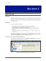
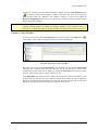
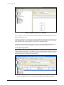
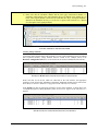
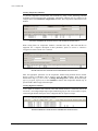
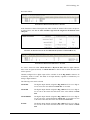
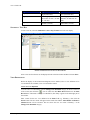
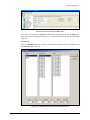
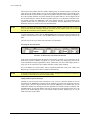
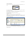
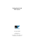
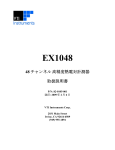
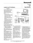
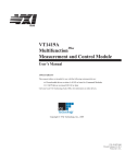
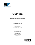
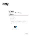
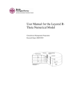
VTICODA
DATA ACQUISITION AND INSTRUMENT CONTROL
SOFTWARE
QUICK START GUIDE
P/N: 82-0119-001
Released October 24, 2007
VXI Technology, Inc.
2031 Main Street
Irvine, CA 92614-6509
(949) 955-1894
VXI Technology, Inc.
2
VTIcoda Quick Start Guide
www.vxitech.com
TABLE OF CONTENTS
INTRODUCTION
Certification ..........................................................................................................................................................5
Warranty ...............................................................................................................................................................5
Limitation of Warranty .........................................................................................................................................5
Restricted Rights Legend......................................................................................................................................5
SUPPORT RESOURCES ...............................................................................................................................................6
SECTION 1....................................................................................................................................................................7
QUICK START ...........................................................................................................................................................7
Overview ..............................................................................................................................................................7
First Steps .............................................................................................................................................................7
Adding Data Acquisition Hardware Modules.......................................................................................................7
Creating a New Test Run......................................................................................................................................8
Creating Strain Gage Channels .......................................................................................................................9
Creating Voltage Channels............................................................................................................................10
Creating Temperature Channels ....................................................................................................................11
Creating Digital I/O Channels .......................................................................................................................11
Starting a Test Run .............................................................................................................................................13
View Definitions.................................................................................................................................................13
Create New View Definition.........................................................................................................................13
VTIcoda Quick Start Guide
3
VXI Technology, Inc.
4
VTIcoda Quick Start Guide
www.vxitech.com
CERTIFICATION
VXI Technology, Inc. (VTI) certifies that this product met its published specifications at the time of shipment from
the factory.
WARRANTY
The product referred to herein is warranted against defects in material and workmanship for a period of one year
from the receipt date of the product at customer’s facility. The sole and exclusive remedy for breach of any warranty
concerning these goods shall be repair or replacement of defective parts, or a refund of the purchase price, to be
determined at the option of VTI.
VTI warrants that its software and firmware designated by VTI for use with a product will execute its programming
when properly installed on that product. VTI does not however warrant that the operation of the product, or
software, or firmware will be uninterrupted or error free.
LIMITATION OF WARRANTY
The warranty shall not apply to defects resulting from improper or inadequate maintenance by the buyer, buyersupplied products or interfacing, unauthorized modification or misuse, operation outside the environmental
specifications for the product, or improper site preparation or maintenance.
VXI Technology, Inc. shall not be liable for injury to property other than the goods themselves. Other than the
limited warranty stated above, VXI Technology, Inc. makes no other warranties, express or implied, with respect to
the quality of product beyond the description of the goods on the face of the contract. VTI specifically disclaims the
implied warranties of merchantability and fitness for a particular purpose.
RESTRICTED RIGHTS LEGEND
Use, duplication, or disclosure by the Government is subject to restrictions as set forth in subdivision (b)(3)(ii) of the
Rights in Technical Data and Computer Software clause in DFARS 252.227-7013.
VXI Technology, Inc.
2031 Main Street
Irvine, CA 92614-6509 U.S.A.
VTIcoda Quick Start Guide
5
VXI Technology, Inc.
SUPPORT RESOURCES
Support resources for this product are available on the Internet and at VXI Technology customer
support centers.
VXI Technology
World Headquarters
VXI Technology, Inc.
2031 Main Street
Irvine, CA 92614-6509
Phone: (949) 955-1894
Fax: (949) 955-3041
VXI Technology
Cleveland Instrument Division
5425 Warner Road
Suite 13
Valley View, OH 44125
Phone: (216) 447-8950
Fax: (216) 447-8951
VXI Technology
Lake Stevens Instrument Division
VXI Technology, Inc.
1924 - 203 Bickford
Snohomish, WA 98290
Phone: (425) 212-2285
Fax: (425) 212-2289
Technical Support
Phone: (949) 955-1894
Fax: (949) 955-3041
E-mail: [email protected]
Visit http://www.vxitech.com for worldwide support sites and service plan information.
6
VTIcoda Quick Start Guide
www.vxitech.com
SECTION 1
QUICK START
OVERVIEW
This guide summarizes the essential steps that are needed during a typical session of running
VTIcoda (i.e. add data acquisition modules, to create and start test runs and to create view
definitions, etc.). It does not, however, replace the complete description of the functionality of
each software module.
FIRST STEPS
The steps described below assume that:
•
•
•
•
All data acquisition hardware that will be used has been correctly installed
The hardware has been acknowledged by the Agilent I/O Libraries (see Section 1: Data
Acquisition Hardware Installation in the User’s Manual)
The instruments have been switched on (otherwise, VTIcoda will not be able to detect the
hardware)
The VTIcoda software has been correctly installed (see Section 1: Software Installation and
Configuration)
After starting the VTIcoda software by double-clicking the CodaAdmin icon on PC’s desktop, a
prompt will appear requesting a user name and password. After successfully entering the login
information, the Coda Admin main window will appear on the screen.
ADDING DATA ACQUISITION HARDWARE MODULES
In the tree structure on the left of the screen, under Hardware Configuration, select the group to
which hardware modules will be added (e.g. VXI Tree).
FIGURE 1-1: ADDING HARDWARE MODULES TO A GROUP
VTIcoda Quick Start Guide
7
VXI Technology, Inc.
In order for VTIcoda to accept connected hardware modules, click the Scan Hardware button
). VTIcoda will then scan for hardware modules connected to the system. Do not start any
(
other operation before the “Hardware scan complete” message is viewed. Next, expand the
Hardware Configuration item in the tree by clicking the + symbol on the left. VTIcoda will then
display the hardware detected.
NOTE
The scanning procedure should only be executed when the hardware setup has been changed (i.e.
replacing existing hardware or adding new hardware modules). After a hardware scan, it is
necessary to re-allocate the hardware (using the Hardware Configuration tab) in the next test run.
CREATING A NEW TEST RUN
To create a new test run, select the Testrun List item in the tree and click the Add button (
in the toolbar. A new, empty test run mask will now be created and displayed.
)
FIGURE 1-2: CREATING A NEW TEST RUN
By default, the new test run is named New Entry. To rename the test run, go to the Testrun name
field and enter a different name that better describes the test run that will be created. After
renaming the test run, refresh the tree display by clicking the Testrun List item in the tree again.
The new, empty test run will now appear in the test run list.
In the Description entry field, provide text that can be used to easily identify the channel (e.g. the
purpose of the new test run). Next step, continue to add as many channels as will be required for
the test run. Do this by right-clicking the large empty area. This will open the context menu. Select
New entry from this menu. This will create a new channel in the test run.
8
VTIcoda Quick Start Guide
www.vxitech.com
FIGURE 1-3: ADDING CHANNELS TO A TEST RUN
After creating a new test run and associated channels, defining the individual parameters of each
channel should be done next.
To allocate a channel to a certain group, for example, double-click the empty field of this channel
in the Group column to open a pull-down menu that offers all groups that have been previously
defined in the VTIcoda Catalogs/Groups section. Select an appropriate group.
Configure the remaining parameters (Signals, Alarms, etc.) in the Hardware configuration tab as
described in Section 3: Hardware Configuration of the VTIcoda User’s Manual.
Creating Strain Gage Channels
When creating a test run for strain gage measurements, remember that strain gages provide a
voltage when measuring signals. This means that, for each measurement channel (providing a
voltage signal) that is defined, a complementary calculation channel must be created to convert the
measured voltage into a strain unit (see example below).
FIGURE 1-4: DEFINING CALCULATION CHANNELS FOR STRAIN GAGE MEASUREMENTS
VTIcoda Quick Start Guide
9
VXI Technology, Inc.
NOTES
1) A calculation channel does NOT require any hardware allocation!
2) Please note that the calculation channel and the strain gage measurement channel it is
assigned to must both have the same transducer ID (to be defined in the Signals tab, see
below, where logical channels 1 and 2 have the Transducer ID “TD_0“ and logical channels 3
and 4 have the Transducer ID “TD_1“). See Section 3: Signals of the VTIcoda User’s Manual
for a description of the signal parameters.
FIGURE 1-5: DEFINING THE TRANSDUCER ID
Creating Voltage Channels
To perform voltage measurements with VTIcoda (e.g using a VXI Technology E1413 64-channel
data acquisition module), voltage channels must be created. In the example shown in the
Hardware configuration tab below, two E1501A SCPs are used in combination with an E1413.
FIGURE 1-6: HARDWARE CONFIGURATION FOR VOLTAGE CHANNELS
Please note that, for all devices which are connected via the VXI interface, the appropriate
parameters in the Group, Host, Mainframe, Instrument, and Board columns must be entered. For
more detail, see Section 3: Hardware Configuration of the VTIcoda User’s Manual.
In the Signals tab, enter the appropriate parameters for the voltage channels, as shown below. For
a complete description of these parameters, please see Section 3: Signals of the VTIcoda User’s
Manual.
FIGURE 1-7: SIGNAL CONFIGURATION FOR VOLTAGE CHANNELS
10
VTIcoda Quick Start Guide
www.vxitech.com
Creating Temperature Channels
To perform temperature measurements with VTIcoda (e.g using a VXI Technology EX1048
48-channel precision thermocouple instrument), temperature channels must be created. In the
example shown in the Hardware configuration tab below, three temperature channels have been
defined.
FIGURE 1-8: HARDWARE CONFIGURATION FOR TEMPERATURE CHANNELS
When setting filters for temperature channels, remember that only 4 Hz and 1000 Hz are
supported. For a complete description of these parameters, please see Section 3: Hardware
Configuration of the VTIcoda User’s Manual.
FIGURE 1-9: SIGNAL CONFIGURATION FOR TEMPERATURE CHANNELS
Enter the appropriate parameters for the temperature channel being defined. Define whether
degrees Celsius or Fahrenheit will be used by using the unit parameter. Next, define the
measurement range (e.g. 10°C to 40°C for Range min./Range max.). Identify the thermocouple
type (e.g. Type K, Type B, etc.) in the Transducer column. Each temperature channel may be
operated with a different type of thermocouple.
Creating Digital I/O Channels
To use digital I/O channels with VTIcoda, ensure that suitable hardware is connected, such as the
VT1533A, a 16-bit Digital Input/Output signal conditioning plug-on. The VT1533A has two ports,
each with eight channels. Each port can be configured either as output or as input.
FIGURE 1-10: DIGITAL I/O CHANNELS - HARDWARE CONFIGURATION
VTIcoda Quick Start Guide
11
VXI Technology, Inc.
Proceed as follows:
FIGURE 1-11: DIGITAL I/O CHANNELS - SIGNALS
In the Transducer column of the Signals tab, define whether the channel will be used as an input or
an output. Please note that the same transducer type must be assigned to all channels of the
same port.
FIGURE 1-12: PASSIVE/ACTIVE OUTPUT PROPERTIES (SOURCE: VT1533A MANUAL)
FIGURE 1-13: DIGITAL I/O CHANNELS - ALARMS
If a value is entered for either Alarm min./max. or Hysteresis min./ max. for digital channels,
these values are ignored. Instead, set Alarm min./max. to Yes in order to define the status that
will be reported.
Channels configured for a digital output will be available for in the Dig. OutCh. column to be
switched by means of events. This holds for all input channels, regardless of whether they are
analog or digital channels.
The following events can be selected:
12
Alarm Max
The digital output channel assigned in Dig. OutCh. will be set to high or
low as soon as the value defined in Alarm max. is exceeded.
Alarm Min
The digital output channel assigned in Dig. OutCh. will be set to high or
low as soon as the actual value falls short of the value defined in Alarm
min.
Alarm MinMax
The digital output channel assigned in Dig. OutCh. will be set to high or
low as soon as the value defined under Alarm max. is exceeded or as soon
as the actual value falls short of the value defined in Alarm min.
In Limit
The digital output channel assigned in Dig. OutCh. will be set to high or
low as soon as the actual value falls short of the value defined in Alarm
min.
VTIcoda Quick Start Guide
www.vxitech.com
Dig. Out Ch.
Digital_Out01
High
if Digital_Input01 =
High (Alarm max.)
if Analog_Input01 =
Alarm min. or max. (<20 mm
or > 80 mm)
if Analog_Input02 =
InLimit (>25 mm)
Digital_Out02
Digital_Out03
Low
if Digital_Input01 =
Low (no Alarm max.)
if Analog_Input01 =
InLimit (>20 mm and <80
mm)
if Analog_Input02 =
Alarm min (<25 mm)
STARTING A TEST RUN
To start a test run, select the Calibration - Start / Stop Testrun item in the tree display.
FIGURE 1-14: SELECTION OF TEST TO BE STARTED
Select a test run from the test run list displayed in the selection window and then click start Start.
VIEW DEFINITIONS
Before the display of the measurement diagrams can be enabled, select a view definition. If no
view definitions are available, a new view should be created.
Create New View Definition
To create a new view definition, click the Change View Definition category in the tree on the left
of the screen, then click the (
) icon or choose the New Data Record function in the Data
Record menu. The header “Change View Definition, New Entry” appears in the main right part of
the window.
Enter a name for the new view definition in the Name field (e.g. EX1048_1), then click the
Insert! button. The new name will appear in the header line and the Add Channel and Remove
Channel buttons will be activated. The tree shows the new view name “EX1048_1” in the
Change View Definition category.
VTIcoda Quick Start Guide
13
VXI Technology, Inc.
FIGURE 1-15: CREATE NEW VIEW DEFINITION
Next, select a test run from the Testrun pull-down menu and a display type from the Design pulldown menu. After creating and naming the new view, determine the channels that will be included
in this view.
Add Channel
Click the Add Channel! button to select the channels that will appear in this view definition. The
New Channel window will open.
FIGURE 1-16: ADDING CHANNELS FOR THE VIEW DEFINITION
14
VTIcoda Quick Start Guide
www.vxitech.com
The left part of this window lists all available channel groups. As the desired group is selected, the
center part of the window displays the list of all Transducer IDs belonging to the selected group.
Mark the desired Transducer ID by a right-clicking and the third part of the window will display a
list of the available channels (only those channels are listed here that have been configured in the
test run selected before). Choose the desired channel, define its view parameters in the line below
the columns and click the Add button. Then select further channels, as required. When all the
required channels have bee selected for the view definition, click the Close button. All channel
definitions will now be written to the View Definition table.
NOTE
Hold the Ctrl button and left-click multiple, single channels. Hold the Shift button and left-click to
select several consecutive channels. With the first click, the first channel of the row is selected
and, with the second click, the last channel is selected.
To add a channel later, simply click the Add Channel button and select the missing channel in the
window as described above. Then, click the Close button. The channel will then be listed in the
table.
The next step will be to pre-define some important view parameters.
Presetting the View Parameters
FIGURE 1-17: PRESETTING THE VIEW PARAMETERS
In the selection fields displayed at the bottom of the window, a number of view parameters can be
defined: the position a channel will appear in a specific window, the diagram type that will be
used, and whether scaling is logarithmic or linear. Furthermore, the values which appear on the xand y-axis can be selected as well as whether automatic scaling will be enabled.
If several channels are selected, these will be assigned automatically to the preset window and
diagram type. The position will also be numbered automatically.
NOTE
If more than eight channels are selected for one window, double traces will appear in a diagram. It
is possible to correct this error later in the channel table.
Adding Channels of Several Groups
Channels of several test runs can be selected for a view. To do so, chose the channels of one test
run and click the Add button. The data from the channels are passed to the clipboard. Switch to
another group, select the desired channels and click the Add button. The channels data will be
added to the data that was already passed to the clipboard. Once channel selection is finished, click
the Close button. All selected channels will now be listed in the View Definition table. Here, the
entries for the channel display can be corrected (the window position, diagram type, etc.) as the
fields of the table can be edited.
VTIcoda Quick Start Guide
15
VXI Technology, Inc.
Number of Charts Displayed
As soon as the channels are listed, the “Number of Charts Displayed” selection field offers 1, 4, 8,
and 16.
Now, select the number of charts that will be displayed on the screen. A maximum of 16 diagrams
per screen page can be selected.
When the “Number of Charts Displayed” is modified, the Update! button appears next to the test
name. Click this button to modifications made to the database.
Table/Diagram Selection
If Diagram is selected, the desired online values are displayed in diagrams.
If Table is selected, the desired online values are displayed in tables. Select one chart (1 – 16) and
one of the positions (1 – 8). The assignment of the channels to charts is not changed, the channels
of one chart are displayed in a table.
The Screen View Channel Table
FIGURE 1-18: SCREEN VIEW CHANNEL TABLE
See Section 4: The Screen View Channel Table for a complete description of all parameters
available in this table.
16
VTIcoda Quick Start Guide