1
OWNER’S AND
OPERATOR’S MANUAL
SOUND PROOF DIESEL
ENGINE
GENERATOR/WELDER
DGW500DM
Vertical, Water-Cooled
4-Cycle Diesel Engine
Table of Contents
Page
1.Safety Guidelines
2.Specifications
3.Use
4.Parts
5.Equipment
5-1. Welding Output Control
5-2. VRD
5-3. Output Remote Control
5-4. Operation Mode Selector
5-5. Meter
5-6. Monitor Lamp
5-7. Earth Leakage Relay
5-8. Auto Idle Feature
5-9. Emergency Stop Switch
5-10. Battery Isolator
6.Initialization and Pre-check
6-1.Checking Engine Oil
6-2.Checking Coolant/Water
6-3.Checking Fuel
6-4.Checking Fuel, Engine Oil
and Water Leakage
6-5.Checking Battery
7.Operation
7-1.Starting
7-2.Stopping
7-3.Emergency Stopping
8.Welding Operation
8-1.Selection-Welding Cable
8-2.Polarity
8-3.Connection-Welding Cable
8-4.Duty Cycle
8-5.Welding
9.Generator Operation
9-1.Output Range
9-2.Output Limitation
9-3.Operation
10.Simultaneous Use of Welding and
Generating
11.Checking and Maintenance
12.Long-term Storage
13.Troubleshooting
13-1.Symptom and Countermeasures
13-2.Error Code Display
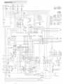
14.Engine Wiring Diagram
15.Generator Wiring Diagram
2
5
5
6
8
8
9
9
10
10
11
13
14
14
14
15
15
15
16
17
17
18
18
19
19
20
20
20
21
22
22
23
23
24
24
26
26
31
32
32
34
35
36
CAUTION: Do not operate the Generator/Welder, or any other appliance, before you
have read and understood the instructions for use.
DGW500DM/ANZ
X750803-3700
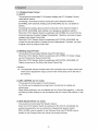
Introduction
Thank you for purchasing Shindaiwa Sound Proof Diesel Engine Generater/Welder.
pa This user manual was created to ensure the safe operation of this equiprnent,
Therefore, the manufacturer of this equipment stroRgly recommends that the
user follow the instructions herein, to avoid unnecessary accidents and
repalrs.
e Please operate this equipment after thoroughly reviewing and understanding
the contents of this manual.
pt Please attach this manual, if the equipment will be sub-leased.
e Please store this manual near the equipment for easy reference.
NFollowing convention will be used throughoutthe manual to indicate the
degree of cautions.
QDanger
Acaution
<Caution>
Cancau$eseriousinjuriesordeath.
Cancauseminorinjuriesordamage
otherproperties.
te the
equipment or
Othertypesofcaution
e Even some of the items noted in reACaution g may lead to serious injuries.
Please read all item and follow all the safety guidelines.
Al-
th. zz lg- tu -'
#・・. ・'
SittfetY"'G.tild・.etin'edis
"/ pt t' tV'.f.-'...." pri...."..de" V'bv.p.
.. .- ..,t-
2・t・
tt'" """'':¢'t " .tt/.W..kw.de .M
Q Danger : Suffocation from exhaust fume
e Exhaust fume from the engine contains many elernents harrnful to human.
Do not operate this equipment in poorly ventilated area, such as inside a room
or in a tunnel.
Q Danger : EIectric Shock
e Close all doors and place locks during operation.
e Do not touch the output terminals during operation.
e Do not insert rrtetal objects (such as pin or wire) into plug-in receptacles.
g Do not touch wiring er electric parts inside the equipmeRt duriRg operatioR.
e Ground every grounding terminal to the earth as set out in the manual. If even
one of all i$ disconnected by mistake or accidents, it will be much more
dangerous for human body than the NO RELAY case, because leaking curreRt
inevitably gees threugh the body.
$ Even though all the terminals of the Ioads have been grounded to the earth,
the bonnet (canopy) grounding terminal should be grounded to the earth.
e Before connecting or disconnecting a plug from output receptacle, always turn
the circuit breaker to OFF position.
e Before connecting or disconnecting a welding cable from output terminals, stop
the engine, and remove the engiRe key.
e Before performing any equipment check or maintenance, stop the engine, and
remove the engine key. A person performing the maintenance should always
keep the key.
O Danger:Bums
e Do not open the radiator cap while operating this equipment or imrnediately
after stopping the equipment, to avoid sustaining burns from hot vapor.
Q Danger:lnjurie$
e Close all doors and place locks duriRg operating this equipment, to avoid
injuries by uniRtentional touching cooling fan and fan belt.
A Cautien : Suffocation frem exhaust fume
es Do not point the exhaust fume toward pede$trians or building.
A Caution : Suffocation from welding fume
pt Be sure to wear a fume proof mask in operation, because welding fume
contains poisonous gas and du$t. Pay attentioB to the airflow direction and
suf('icient ventilation also in order {o prevent frorn inhaliRg the fume.
A
Caution : lnjuries to eyes and skin
ev Be sure to wear spark protection glass(es), long-sleeve shirts, gloves, etc. in
erder to protect eyes and skin from harmful spark in welding.
@ Battery fluid contains diluted sulfuric acid. Avoid coRtact with eyes, skin or on
clothing. If the acid come$ in contact, especially with eyes, flush with a lot of
water, and contact your physiciaR immediately.
k Caution : EIectric shock
g Do not flu$h water onto the equipment nor operate it in the rain.
-2-
A caution:Explesion
@ Do not use the equipment or charge the battery, in the case the battery fluid
Ievel is Iower than the LOWER level.
dy Battery may ernit some cornbustible ga$, so keep it away frorn fire and sparks.
A
Caution : Fire
ee The equipment uses Diesel Oil as a fuel. When refueling, always stop the
engine and keep away from fire. Moreover, always wait until the engine cools
down before refueling,
g Always wipe any drip of Diesel fuel or lubricatioR oil. Do not use this equipment
when a leak is found. Repair the equipment before use.
e femperature around muffler and exhaust can get extremely high. Keep any
inflammable items (such as fuel, gas, paint, etc.) away from the equipment.
pt Keep any inflamrnable iterns and easily burning items away from the place in
welding, because welding splashe$ spatters.
e Always operate this equipment on flat surface and, at lea$t 1 meter away frorn
any objects (wall, box, etc.).
e Do not connect AC output to any indoor wiring.
e Always wait until the equipment cools down, before placing any covering
materials for storage.
: Bums
A Caution
e
Do not touch the engme and rnuffler during operation and irnmediately after
stopping the equipment, for the temperature can reach extremely high.
e
When checking engine oil or changing oil, always stop the engine, and wait
until the engine ceols down. If you open either the oil gauge or the oil plug
during operation, hot oil may cause some injury.
e
Be sure to wear Ieather gloves, apron, shoe covers, eye protection glass(es)
(mask), safety shoes, safety cap, and Iong sleeve shirts, because welding
splashes spatters.
e
Do not open the side door during operation and immediately after stepping the
equipment, because some parts/components (flexible tube, resistors, etc.) can
reach very high temperature inside the equipment.
A Cautien:lnjuries
pt When Iifting the equipment, alway$ use a lifting lug. Do not Iift the roping lug,
for it may cause equiprnent to drop due to roping Iug breaking off.
e When carrying the equipment by trucks, fix it strongly to keep the equipment
from sliding.
dy Always place the equipmeRt on a flat and stable surface, to keep the equipment
from sliding.
& When starting the eRgine, turn eff the connected equipment and set the circuit
breaker to OFF position.
@ Do not move the eq uipment during operation.
g When performiBg equipment check and maintenaRce, alway$ stop the engine.
tw Do not operate the equiprr}ent, if the equipment is being modified or if the parts
are removed.
-3-
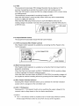
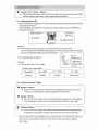
X LocationofWarninglabels
When the warning labels become unreadable or damaged, place new labels on
the appropriate locations, a$ specified in the followiRg figure.
When ordering the label, use the following part numbers.
(l) Suffocation from exhaust furvie (No. 19402-OOI94)
@ Suffocation from welding fume (No. 19402--OOt95)
@ Electric shock (No. 19402-OOI93)
@ Fire (No. 19402-OO166)
@ Injury (No. 19402-OO199) @ Burns (No. 19402-O0200)
@ lnjury (No. 19402-O0207) @ Burns (No. 19402--O0201)
@ Injury (No. 19402-O02fO) @ Burns (Ne. 19402-O0256)
2
7
1
9
6
gggssige
4
,
.
".,
CE)pt e. fi.
t
slj .e le O
}sigillt ts '.
]illiiiiilili
5
gept
,
g{[[Illfowh
.
6
3
<(EII sg
st
,
,
`
,
ff
'
2
"
.
g
.
8
Q
5
g
"
"
ff
"
e
e
-4-
.ve tw t. ... di -.'tign$..X
pt' .ak 1....,, k.
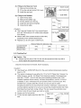
2.,.ww.Spepiflpmtk
.r
,., "'
.. -i,.. f., . X/E,ltw- '..,;l .ev
". .,mu' ",' .?tw"'I e- t'-';y rvM-- ":,. w. ..
N'
.,."
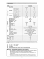
DGW500DM
Model
GeneratingMethod
RotatingField
ii・
OPERATlON
DUAL
SINGLE
RatedCurrent(A)
RatedVoltage(V)
DutyCycle(O/o)
CCMODE
CVMODE
480
23e
39.2
29e2
60
80
CurrentAdj.Range(A)
60---500
30-280
WeldingRod(¢)
GougingRod(¢)
RatedCurrent(A)
2.6-8.0
3.2-9.5
480
2.0--6.0
RatedVoltage(V)
39.0
22.5
60
80
DutyCycle(e/e)
VoltageAdj.Range(V)
12'
WeldingWire(¢)
RatedSpeed(min-i)
3.2-5.0
230
14-40
14-29
O.6-2.4
O.6-2.0
3ooe
MAX85
NoLoadVoltage(V)
RatedFrequency(Hz)
RatedSpeed(min'")
50
3000
Phase
RatedVoltage(V)
PowerFactor
RatedOutput(kVA)
t-Phase
240
3-Phase
415
1.0
O.8
as
1O.8
CentiRuous
Rating
KubotaV1505
2.diiS
Model
Type
Displacernent(L)
Vertical,Water-Cooled4CycleDieselEngine
1.498
29.0/3600(Grosslntermittent)
RatedOutput(kW/rnin-i)
ASTMNo.2DieselpeuelorEquivalent
Fuel
APICIassCDorHigher
LubricantOil
LubricationOilVolume(L)
6.0(Effective2.0)
CoolingWaterVolume(L)
5.6(SubTankCapacityO.8Lincluded)
StartingMethod
StarterMotor
75D31R
Battery
FuelTankCapacity(L)
63
1680
700
950
613
co= Length(mrn)
E.9 Wiclth(mm)
6ee Height(mm)
DryWeight(kg)
e
as
3- U$"
dy
CC Pewer for Stick Welding
@
@
g
CV F)ower forWire Feeder
Arc Gouging
Power Source for Lights, EIectric fools and Home Appliances
A Caution : Damage to the equipment or other properties
@ The equipment is designed for the above purposes only. Do not use it for the
other purpose. When it will be used for the equipment with the
microcemputers coBtrol or for the ultra--precision devices, the Ioad may be
malfunctioned.
@ Whenever connecting to use medical equipment or appliance$, be sure to
consult with the medical equipment company, doctor or ho$pital personnel.
-5-
as.Mes..xiil#iilgli.liliill"..'k・.・'ig-ig.'t-l・/l・,klj-,tj.'/s'/r-.g・i-':.-/j-g・,x・tR.・i51X'/l///l'lg-itff,-g-,/LgS・,,/:llsl.s-tt,<,s-/Si・,r.,,tli.il--iiX/r'.Xt'tg,'S.g'・¥,/'e,・.kl.ta'tw,/j.・/j.#"S£es,....・,gsl.S/.,L・,//'IE'/Eig,/・・2/・f-//j./:.X.,,S-,,S,-.,sf','I・ssi.i・S-・,,"pt",,S.・E-'S',gE・,・e-i'E-wi.an.i'g-i./S-ltr.,l・X,-
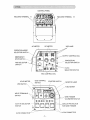
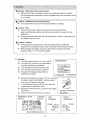
CONTROL PANEL
LA
WELDING TERMINAL
l
-l-1levv!s
gias'ee@es
aj Q t w " n )
Jf'
tt.-e6-e.eseaj6es1]S,l-
WELDINGTERMINAL B
iWE
XpmI!1m]lvWeflFl/
gkSFgljg,
Xo
oo/
DC METER
AC METER
VRD LAMP
x.
×/×
SELECTORSWITCH
OPERATIONMODE/×
7Xur1Xew
1g,g
1gNZ -7"'""""OUTPUTCONTRoLDIAL
x
EMERGENCY
STOPSWITCH
gggi!ptE,,p.'
of
ko-
SWITCH
rv
=-SINGLE/DUAL
diSELECTOR$WITCH
@:f@×i--thw,fi
pare
x/
ptcv/ccSELECTORSWITCHat
eR.dvas
RODSELECTOR
ARC CONTROL DIAL
IDLECONTROLHOURMETERSTARTERSWITCH
SWITCHvMONITORLAMP
×ll
I
/F-,
/k
9-PINCONNECTOR
eele?lpgtpmm.
@ il
@
Nx
?-.
/
rfi
X・--:
L
FUELMETER
x
Lut
es>
x,
SWITCH
IX
u <<ep>)
/LeJ
lrc-,
mWELDTERM(NA}
LS
42V/M5VSELECTOR/SWITCHNS
i'×
x
ll
×1tejx
vRDSWITCHX//
t
WIREFEEDER
VOLTMETERSWI
if
CIRCUITPROTECTO
Ril
n-
FORWIREFEEDER
ee
14--PINCONNECTOR
-6-
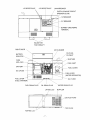
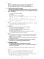
1-P RECEPTACLE
MAlN BREAKER
3--P RECEPTACLE
EARTHLEAKAGEC
BREAKER(ELCB)
<<i(gl51
×
i xx--
gsw
@,・
-/-
W'F"-,,,,-
A
1-PBREAKER
;o×
LNL
x
3-PBREAKER
)---l-
BONNETGRO
TERM1NAL
eeA.
gggsgggsEgggEg
eemegeeggsasee
:
gg:gggggggggggoasm=nmurcrmacrcrurv"as
]
-×]
-h`-s-・--s.....
HOLES FOR
THE FORKLIFT
RIGHTDOOR
BATTERY
ISOLATOR
1
×"-..
isg-`[-e=lli
,:,,-,S.As-ri/}iF
BATTERY
OILGAUGE
e
OILINLET
i/ii7
gegan
mu
eegeezgwaeeggggg
FUELLEVER
es1
-
/fo
-..
×G!)
Ej.,,.,,,tli-si/g!E,:.;s,geEtiE,.,g・tr---'---.-ww-I-.-Y
(60A,20A)
××
OILPLUG
sasx
sil
FUSE
AIRCLEANER
SUBTANK
-g/
FUELCOVE
T
-FUELLEVER
.
(WATERSEPAR
-
OILFILTER
Ie.oneeeoe<btl
(FUELSTRAINER)Fl
FUEL DRAIN PLUG
OIL DRAIN PLUG
LIFTING LUG
.A --g-
ll
//
T,,,,,,illE-
e
WATER DRAlN PLUG
MUFFLER
- /wawwmug
--
/
muww
wa-
-7M
EXHAUST PORT
[llllll#lil
K
PINGLUG
/FUELINLET
N
TOP PLATE
ttttt'-ela.・f.tk,'Eiec.fftsgpaett.mugag-ee-'tts-.eeeeeett・v--・,//,ttktt.if:i'Eissg}g"i'X'・et-tY,,,sltZ//,,ii./ge,f'--V・"X'//r,Z'g'ii"g'llt・.#,ieesci'k.dii.,s/Y/,---'.・{・.i.X,1/k-g,",2/,,/1,/lig/Y・・i;l,x.g--.,iS.,S・'i-'ee..'tX.・tX,E".tk・.,,・ixvg.,g,vles"'k'-tt/v・-Mi'-""・,.#//eeg,x,,.
5-1. Welding Output Control
(1) CV/CC
The equipment incorporates CV (Constant Voltage) and CC (CoRstant Current)
characteristic feature.
Connecting a wire feeder and then turning the CC/CV Selector Switch to
[CV-WIRE], semi--automatic welding such as MIG, MAG SS, etc. is available to
perform.
Connecting the welding cables and then turning the CV/CC Selector Switch to
[CC-STICK, GOUGING], stick welding or arc gouging is available to perforrn.
When the CV/CC Selector Switch is positioned at [CV-W[RE], the current from the
terminals becomes Constant Voltage Characteristic. Therefore, you have to adjust
voltage by the Output Control Dial.
When the CV/CC Selector Switch is positioned at [CC-STICK, GOUGING], the
current frorn the terminals is Constant Current Characteristic. Therefore, you have
to adjust current by Output Control Dial.
ag
(2) Welding Output Pre-Set
The equipment incorporates Welding Output Pre-Set feature.
When the CV/CC Selector Switch is positioned at [CV-WIRE], CV Output voltage
can be Pre-Set by the Output Control Dial
When the CV/CC Selector Switch is positioned at [CC-STICK, GOUGING], CC
Output current can be Pre-Set by the Output Control Dial.
<Caution>
e The applicable remote controller with 9-Pin Connector has an Output control dial
which can be adjusted the output current in the remote area prior to the dial on
the machine.
(3) ARC CONTROL (for CC mode)
The equipment incorporates Arc Control feature.
Arc Control can be adjusted by turning the Arc Control Dial fer suitable arc
petformance.
Stable (Mild) welding arc can be obtained with Arc CoRtrol Dial negative(-) dial side
and Strong (Crisp) welding arc can be obtained with Arc Control Dial positive( +) dial
side.
(4) ROD SELECTOR (for CC mode)
The equipment incorporates Rod Selecter feature.
When the CVICC Selector Switch is pesitiened at [CC-STICK, GOUGING], the
welding characteristics can be switched by changing Rod Selector Switch.
[CELLULOSEI mode is suitable for the Cellulose Rods and [OTHERS] mode i$
suitable for the Gouging Rod$ and ordinal rods except cellulose.
-8-
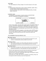
5-2. VRD
The equipment incorporates VRD (Voltage Reduction Device) feature, for the
purpose of protecting an operator from electric shock with welding current.
When the VRD Switch is turned to [ON], the voltage changes to 35V or lower during
no welding period.
The equipment is incorporated in monitoring function of VRD.
When the VRD Switch is turned to [ON], Green VRD Lamp will be autorrtatically
turned on at [BELOW 35V] side.
When the Red VRD lamp will be turned on at [AT OR ABOVE 35V] side, the
welding voltage i$ exceeded more than 35V accidentally or while the VRD switch is
at [TEST] mode.
gHHBi
FA
AE
ex,ofM--MVnt-gast33nsmx
A
rr
kesJLe
HgE
1 HHev
ee
rcrermllmmA11ouTPUTS
VRD LAMP
5-3. 0utput Remote Control
The equipment incorporates Output Remote Control feature.
(1) 14-Pin Connector (Wire Feeder Control)
Wire Feeder Control operation is available by connecting the Wire Feeder to the
14--Pin Connector
gy
ue-ix
LevR
1
>h
l
・lma
lwaig'
pal@e l
ei.Aix
ll
@@ej6@e
-i
14-PINCONNECTOR
@
e
@
WIRE FEEDER
X
(2) Weld Terminal$ Switch
Wire Feeder Control operation is available by turniRg the Weld ferminals Switch to
[REMOTE CONTROL]
When the Weld ferminals Switch to IWELD TERMINALS ON], the weldiRg voltage
is always supplied at machine's welding terminal.
When the Weld ferminals Switch to [REMOTE CONTROL], the welding voltage will
be supplied at machine's welding terminal by pre$sing the wire feeder torch trigger.
<3) Wire Feeder Voltmeter Selector
$electing Wire Feeder Voltrneter Switch can be $witched the voltmeter indication
polarity which is equipped oR the wire feeder unit.
(4) 42V / 115V Selector
Selecting 42V 1 115V Selector Switch can be switching the $upply voltage for the
required output voltage based on the wire feeder specification.
<Caution>
g 42V/ M5V Selector $witch is available only forA-side Output Remote Control.
B-side Output Rernote Control i$ $et a$ 42V only due to the regulation.
-9-
(5) Circuit Protector ferWire Feeder
When the over curreRt (more than 5A) is flown into 14-Pin Connector for wire
feeder, the Circuit Protecter will be activated to shut off the current.
<Caution>
g Resolve the over current issue to proceed the necessary rnaintenance when the
Circuit Protector was activated, with reset the trip button.
(6) 9-Pin Connector (Remote Control)
Remote Control operation is available by connecting the compatible Remote
Controller to the 9--Pin Connector. Ybu can adjust the welding current (in CC
condition) or welding voltage (in CV condition) in the remote area from the machine.
x.ss
pmIgmeIl:l
tl
m>
wr
1
its
1
//r
<of
@2
coAA
@@
9-iPlN
9-iPIN
CONNECTOR
l
@@@e@co
@
i'
i・
g
e-
.
inpt
REMOTE CONTROLLER
(Compatible)
5-4. 0PERATION MODE SELECTOR
The equipment incorporates Operation Mode Select feature.
Below three modes can be $elected by the Operation Mode Selector Switch po$ition.
[GEN. WELDERI : Both Welder and GeRerater mode
[WELDER ONLY] : Only welding function mode
[GEN. ONLYI : Only generating function mode
5-5. Meter
The equipment incorporates digital meters, voltage & arnperage of welding output
and also 3-Phase Voltage & frequency of AC output.
(1) DC Ampere Meter tt Vblt Meter
Each meter displays welding voltage and amperage in Side A or Side B terminals.
When the SINGLE /DUAL Selector Switch is positioned at [SINGLE], the meters do
not display the amperage or the voltage in Side B terminals.
<Caution>
ge While operating at no-Ioad, if the CV/CC Selector Switch is set as ICV-WIRE],
DC Volt Meter is indicating desired voltage by Output CoRtrol Dial.
(There is no display at DC Ampere Meter while no-load.)
* While operating at no--load, if the CV/CC Selector Switch is $et as [CC--STICK,
GOUGING], DC Ampere Meter is indicating desired amperage by Output Control
Dial.
(There is no display at DC Volt Meter while no-Ioad.)
@ During actual welding work, both DC Volt Meter t Ampere Meter displays actual
output. Both displays will be back to the pre-set value after counting about
8seconds with blinking dot on the DC Volt meter.
-10-
(2) AC Meter
The meter displays the 3-Phase voltage (U-V) and the frequency in AC output.
<Caution>
tw While Operation Mode Selector Switch is [GEN. WELDERI or [GEN. ONLY],
AC Meter displays 3-Phase voltage and frequency.
When the Operation Mode Selector Switch is [WELDER ONLY], AC Meter
display will goes otf.
5-6. Moniter Lamp
The equipment is incorperated in monitoring function of WArrER TEMP,
BATTERY CHARGING, OIL PRESSURE, OVERHEAiTl
OIL PRESSURE
WArl"ERTEMP
"caITea
;relpa
e
t ssr
o
r------------mM.I
BAI"TERY CHARGE
OVERHEAT
Under normal condition, when the starter switch changes from [STOPI to [RUN], all
the lamps of BATTERY CHARGING, OIL PRESSURE and OVERHEAT turn ON.
When the engine starts, all the lamps turn OFE When abnormality i$ detected on
other than OVERHEAT] the corresponding monitor larnp will flash, and the engine
automatically shutoff.
When the automatic shutoff is engaged, turn the starter switch to [STOPI position
once, and then restart the engine. In the event the automatic shutoff is engaged
next time, check which lamp turns ON or OFF and point out where is the
abnormality.
(1) Coolant/Water Temperature Moniter Lamp
Q Danger: lnjuries
e Close all doors and place Iocks during operating this equipment, to avoid
injuries by unintentionally touching cooling fan and fan belt.
Q Danger: Burn$
e Do not open the radiator cap while eperating this equipment or immediately
affer stopping the equipment, to avoid sustaining burns from hot vapor.
A Caution: Burns
& Do Rot touch the engine and muffler during operation and immediately after
stopping the equipment, for the temperature can reach extremely high.
When the water temperature rises abnormaHy, the ceolant/water temperature
menitor lamp will flash, and the automatic shutoff will be engaged.
When thi$ occurs, check the coolant/water reservoir tank, and replenish if needed.
(Referto if6-2. Checking coolantlwaterg )
lf the water Ievel is Rormal, there may be a pos$ibility ef overloading. Alway$ use
the equipment within the rated duty cycle and output power.
-11 -
(2) Battery Charge Monitor Lamp
When the battery turns unable to be charged duriRg operation, the battery charge
monitor lamp will flash and the automatic shutoff will be engaged.
In the event this occurs, consult with the authorized distributor or our engineering
section.
<Caution>
e The battery charge monitor cannot detect the degradation of the battery Ror the
battery fluid level. Check the battery fluid level periodically.
(Referto if6-5. Checking BatteryS )
(3) Oil Pressure Monitor Lamp
Q Danger:lnjuries
pt Close all doors and place locks during operating this equipment, to avoid
injuries by unintentionally touching cooling fan and fan belt.
A caution:Burns
e Do not touch the engine and rnuffler during operation and immediately after
stopping the equipment, for the temperature can reach extremely high.
e When checking engine oil, always stop the engine, and wait until the engine
cools down. If you open either the oil gauge or the oil filter cap during
operation, hot oil may cause some injury
When the engine oil pressure drops during operation, the oil pressure monitor Iamp
will flash, and the automatic shutoff wi
be engaged.
When this occurs, check the engine oi
Ievel, and replenish to the maximurn level if
needed.
<Caution>
e The engine oil pre$sure monitor cannot detect the degradation of engine oil itself
Please check the engine oil periodically, and change if needed.
(Referto ffM. Checking and MaintenanceX )
ee Check the fuse next, when the abnormality, other than WATER TEMR BATTERY
CHARGED OR OIL PRESSURE is detected. If the fuse is burned out, consult
with our authorized distributor or our engineering section, because there may be
an abnormality of electric/electronic parts or wiring and repairing may be
required.
(4) Overheat Monitor Lamp
OVERHEAT menitor lamp may flash in the case the rriachine is used exces$ively
over the duty cycle or over load.
When the OVERHEAT monitor lamp is blinking, this equipment cut$ the out put off.
When this overheat occurs, there may be a possibility of overleading. AIways use
the equipment within the rated duty cycle and output power.
<Caution>
tw There may be a case that the lamp will not flash, depending on the welding type
er the weather condition.
-12-
5-7. Earth Leakage Relay
O Danger : Electric Shock
e Ground every grounding terminal to the earth as set out in the manual.
If even one of all is unconnected by mistake or accident, it will be much rnore
dangerous fer human body than the NO RELAY case, because leaking current
inevitably goes through the body.
e Even though all the terminals of the loads have been grounded to the earth,
the bennet (canopy) grounding terminal should be grounded to the earth.
e Grounding should be rnade after the engine is stopped.
e Whenever the earth Ieakage relay has activated, you should always repair the
Ieaking place first of all.
The equipment is provided with the earth leakage relay in the Circuit Breaker to
detect any leakage arisen due to the troubles as insulation failure of the Ioad while
the generator is running. And cutting off the circuit for protection against any
accident such as electrical shock resulting from the trouble.
The specifications of the earth leakage relay:
e Rated Sensitive Current: 30mA (or below)
(Grounding resistance: 5009 or below)
(1) Grounding Werk
The qualified electrician should perform the grounding work of the foHowing 2
points(5009 orbelow).
e The Outer Bonnet of this equiprnent (bonnet grounding terminal)
e The Outer Bonnet of the Ioad
BONNET GROUNDING
TERMINAL
llll>×.x. .・e
l'
se
'
fi
GROUNDING ROD
<Caution>
ee IR the event you cannet ground the generator to the earth, consult with the
authorized distributor er our engineering section.
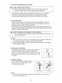
(2) Operation Check
Before operating the equipment, check always if the
device can work duly a$ $hown in the following
procedure.
e[SIi:lle
(D Start eRgine after turning the Idle Control Switch to
[HIGHI.
@ Turn (Push-up) the [!iLCB (lever) to [ON] position.
@ Push the test button. Thedevice i$ found to be
normal when the ELCB (lever) tums to [OFFI.
EEgesg
ln the event you cannot complete all steps in the above procedure to the end, the
device is out of erder. Con$ult with our autherized distributor or our engineering
section to repair.
-13-
(3) The Earth Leakage Relay has activated
A Caution : EIectric Shock 1 lnj uries
e Be sure to disconnect all the loads to the equipment when turniRg the
breakers ON again, after the earth leakage relay has activated.
When the earth Ieakage relay has activated, the ELCB (lever) turns to IOFF].
In the case, stop the engine promptly and find the Ieakage peint to repair.
After repairing Ieakage point(s), return (push up) the ELCB (lever) to [ON].
5-8. Auto Idle Feature
TheAuto ldle feature is to setthe engine speed low automatically (in about 8
seconds) for the purpose of reducing noi$e and fuel consumption, whenever no
welding operation or electric supply is petformed,
IB the case of using theAuto ldle feature, turn the ldle Control Switch to [AUTO].
By the condition, the engine automatically moves to high speed, whenever welding
operation or electric supply starts.
A Caution : Damage to the equipment or other properties
e Turn always the ldle Control Switch to [HIGHI, when the load is incorporated
with any magnet switch.
<Caution>
e When the load of less than O.5A is connected to use, the Auto ldle feature does
not function sometimes. Therefore, turn the switch to [HIGH].
e When welding operation or electric supply performs alternately or intermittently,
turn the switch to [HIGH].
5-9. Emergency Step Switch
The Emergency Stop Switch is used to stop the engine in
emergency. By pushing the switch, the engiRe stops.
Be sure to restore the Starter Switch to [STOP] and reset
STOP
tw×
the Emergency Stop Switch, tuming clockwise after using
the switch.
RESET
5-10. Battery l$olator
When turRing the Battery lsolator Switch to
[OFF] positien, the eRgine electric circuit
does not get battery power.
o es
ex
D
o
OFF position
o
tw
ew
@ Do not turn the Battery lsolator positioR while in operation, it may cause the
-14-
o
ON position
<Caution>
serious damage on the unit.
D
//l・i.,,,...k...eeas,i'gtX.wapatttt"tleseegeeeeeew--i;'tg,'£',:#l,,ve/E'/l,i-,f-l'.k,,,i"e',fiieettG3/"si,l//ftas'S'ee,ee.tt//・%',,ifli・・,,/:/lll・,tk/;-gX,,eett'pteett.eetttt'i,li,','t'eees.ss
A caution:Fire-BumsgInjuries
e When checking engine, always stop the engine, and keep away from fire. Wait
until the engine cools down, before performing any checks.
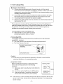
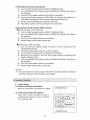
6A. Checking Engine Oil
When checking for engine oil, be sure to keep the equipment leveled, and insert the
oil gauge all the way in.
Prior to starting the equipment, rnake sure to fill the engine oil to the UPPER line
Rd.
G,L,
RIGHT DOOR
huclwam-----nt
OIL INLET
OIL PLUG
,
-ij.-.-
ff
OILGAUGE
ooOILDRA
through the oil inlet
l.o.-edo.I
<Caution>
e lf the equipment is not leveled, you cannot obtain accurate oil level.
De not overfill (over UPPER line) the engine oil. The excessive amount of engine
oil may darnage the engine (inside the cylinders)
(6.0L)
- Selecting proper engine oil UpPER LEVEL
<Caution>
:EFFECTIVE
e Use the API class CD or higher. LOWER LEVEL
(4.0L)
Viscosity and femperature
Temperature
Over+20℃
+1O.v+20℃
-1o・v+4o℃
Viscosity
SAE30
SAE20
SAE1OW/30
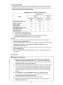
6-2. Checking Ceolant / Water
Q Danger:lnjuries
e CIose all doors and place locks during operating this equipment, to avoid
injuries by unintentionally touching cooling fan and fan belt.
O Danger:Burns
e Do not open the radiator cap while operating this equipment er immediately
after stopping the equipment, to avoid sustaining burns frem hot vapor.
A Caution:Burns
ge Do not touch the engine and muffIer during operation and lmmediately after
stopping the equipment, for the temperature can reach extremely high.
Check to $ee if the coolantlwater level is between FULL and LOW Ievels in the sub
tank. If the coolant/water is below the LOW level, fiH the tank and the radiator
accordingly.
-G5-
(1) Filling to the Reserveir Tank
RIGHT DOOR
O Rern ove the sub tank cap.
SUBTANKCAP
@ Fill up the sub tank to the FULL level.
@ Install the cap back,
(2) Filling te the Radiator
O Open the top plate.
@ Removetheradiatorcap.
@ Fill the radiator up to the top.
FULL
@ lnstall the cap back and tighten.
F
@ CIose the top plate.
LOW
SUB TANK
<Caution>
e Use Long Life Coolant (LLC), for prevent freeze
RADlATOR CAP
TOPPLATE g:l
and rust. (30%mixture LLC is filled when shipped
from factory)
e Mixture ratio of the coolant should be 30%-45%,
iiiilliliii#l
depending on the ambient temperature.
e Replace LLC at every year or 2000 hours.
WATER INLET
Mixture Ratio (for reference only)
LowestAmbient
Temperature
-15℃
-20℃
-30℃
3oo/,
350/o
45O/o
MixtureRatio
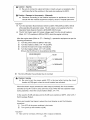
6-3. Checking Fuel
A Caution:Fire
e Always wipe any drip of fuel. Do not u$e thi$ equiprnent when any leak is
found. Repair the equipment before use.
Check for the fuel Ievel in the tank. Add if necessary.
<Caution>
ge Use Diesel fuel, ASTM D975 No.2-D in the event ambient temperature reaches
down to -5℃.
& The engine is designed to use either No.1-D or No.2-D Diesel fuel, However, for
better economy, use No. 2-D Diesel Fuel whenever possible. Attemperatures
less than -7℃(20T ), No.2-D fuel may pose operating problems (see ℃old
Weather Operation which follows), At colder ternperatures, use No.1-D fuel (if
available) or use a "winterized" No.2・-D (a blend ef No.1-D and Ne.2-D). This
blended fuel is usually called No.2-D also, but can be used in colder
temperatures than No.2-D fuel which has not been "winterized". Check with the
services statiens operator to be sure you can get the properly blended fuel. Note
that Diesel fuel may foam during a fill--up. This can cause the automatic pump
nozzle to shut off eveR though your tank is net fuH.
ig Always use the fuel strainer.
ee Fill the fuel tank slightlyless than the FULL
'IZANK CAP
FUEL COVER
FUEL
STRAINER
tank.
FUEL iNLET
-16-
6-4. Checking Fuel, Engine Oil and Water Leakage
ACaution : Fire
e Do not use this equipment when a leak is found. Repair the equipment before
use.
Be sure to check any leakage for fuel, oil and coolantiwater at the hose connections
by opening side doors. Whenever checking any fuel leakage, turn the fuel Iever
[OPEN] and be sure to clo$e the fuel lever after checking.
6-5. Checking Battery
A Caution : lnjuries to eyes and skin
e Battery fluid contains diluted sulfuric acid. Avoid contact with eyes, skin or
clothing.
e lf the acid cemes to contact, especially with eyes, flush with a lot of water, and
contact your physician immediately.
A Caution:Explosion
e Do not use the equipment or charge the battery, in the case the battery fluid
level is Iower than the LOWER level.
e Battery may emit some combustible gas, so keep it away from fire and sparks.
A caution:Fire
e Battery may emit some combustible gas, so keep it away from fire and sparks.
TERMINAL UPPER
(I) Check the fluid Ievel. If the level is near or Iower
than LOWER level, add distilled water until the fluid
LEVEL
Ievel reaches UPPER level.
@ Make sure that the battery cables are firmly secured
LOWER
LEVEL
to the post$. nghten the clamps if nece$sary.
<CautioR>
e Make sure to turn to [OFFI the Battery lsolator Switch before attempting to
maiRtain the battery terminal.
ge Check the hydrometer of the battery fluid. If it falls below 1.23, the battery requires
recharging. Please consult with our authorized distributor or our engineering section.
X Replacingbattery
(l) Turn the Battery lsolator Switch to [OFF]
@ Remove the clamp and cable from negative H post
[.m] posT
on the battery, (Remove always negative side first)
@ Remeve the hold-down clamp from the battery.
@ Remove the clamp and cable from positive [+] po$t
on the battery,
@ Rem ove the battery from the seat.
e999
HOLD--DOWN CLAMP
(lnstall always the cable to the positive [+] post in the new battery fir$t.)
<Caution>
@ Usethefollowingbattery.
75D31R
M17-
BAI"TERY
ISOLAI"OR
BATTERY
e
)K Reinstall a new battery in the reverse order.
INS. CAP
[+l POST
O Danger : Suffocatien from exhaust furne
e Exhaust fume from the eRgine contains rnany elements harmful to human.
Do not operate thi$ equipment iR poorly ventilated area, such as inside a room
or in a tunnel.
A Caution : Suffocation from exhaust fume
e Do not point the exhaust fume toward pedestrians or building.
A Caution:Fire
e femperature around muffler and exhaust can get extremely high.
Keep any inflarnmable items (such a$ fuel, gas, paint, etc.) away from the
equipment.
e Always operate this equipment on flat surface and, at least 1 meter away from
any objects (wall, box, etc.)
A caution:Injuries
e Always place the equiprnent on a flat and stable surface, to keep the
equiprnent from sliding. Be sure to lock the wheels for the wheeled models.
$ Before starting the engine, be sure to disconnect the loads and setthe
breakers (Main, 1-R 3-P) to [OFF] position.
7-1. Starting
MAIN BREAKER
(Z) Turn thebreakers(Main, 3-P, 1-P) to [OFF]
@ Turn the every FueHever (on Fuel Strainer
N
@offf・
and Water Separator) to [OPEN],
1
@ Turn the Battery lsolator Switch to [ON]
@ Turn the ldle Control Switch to [AUTO].
:[lllllllillii]・t
"rv"nee
@ Ensure the Emergency Stop Switch is
//3-P BREAKER
positioned to release.
1 -P BREAKER
@ When the temperature is below -5℃, turn and keep
the Starter switch to PREHEAT until the preheat
Iamp turns off (about 5 seconds).
@ Turn the Starter Switch to [STARn and then the
engine starts by the starter motor.
@ Release the Starter Switch, as soon as the engine
SWITCH SWITCH
GFF O
B/SCI'TERY lSOLATOR
has started.
@ Keep the engine idle for about 5 minute$.
EMERGENCY STOP S'l'A RTER
O tw D
ON position
FUEL
STRAINER
WATER
SEPARATOR
wa wa wa E]
as {ers} @
CLOSE
CLOSEI
@-r@-@ @@@o @@o
or yr
....e ae
OPEN
IDLE CONTROL SWITCH
- G8 --
OPEN
<Caution>
tw Do not drive the starter motor for more than 15 seconds successively.
g lf you need to restart, wait for 30 seconds or more before retry.
dy Once the engine has started, never turn the starter switch to [STARn.
x
Restart after stopping due to fuel shortage
This equipment is incorporated in automatic vacuuming air feature, Therefore, even
though the engine stops due to running out of fuel, you can restart the engine easily
by the following steps.
O Tu rn the Sta rter Switch to [S TO P] .
@ Fillthefuel.
@ Turn the ldle Control Switch to [AUTO].
@ Turn the Starter Switch to [STARII and drive the starter motor for about 1O
seconds.
@ Release the Starter Switch, as promptlyas the engine started.
@ Wait forabout 1 minute to vacuum the air out. The engine speed becomes
stable when the air is extracted.
<Caution>
e Never turn the engine HIGH speed or connect the loads until the air is extracted
completely (the engine speed becomes stable)
7-2.
O
@
@
Stepping
Turn (Push-down) the breakers (Main, 3-P, 1-P) to [OFFI.
Turn the ldle CoRtrol Switch to [AUTOI.
Keep the engine idle (cooling down) for about 5 minutes.
@ Tu rn the Sta rter Switch to [S TO P].
@ After the engine has stopped, turn the every Fuel Lever to [CLOSE].
@ Turn the Battery lsolator Switch to [OFFI position.
<Caution>
g WheR the engine does not stop in spite of turning the Starter $witch to [STOP],
Turn the Fuel Lever on Fuel Strainer or Water Separator to [CLOSE], then the
engine will stop in a few minutes.
In this case, be sure to consult with our authorized distributer or our engineering
section and ask to repair.
ig Do not attempt to turn to [STOP] position while actual welding or utilizing AC
pewer source, it may cause the serious damage on the unit.
7-3. Emergency Stopping
The Emergency Stop feature is incorperated in the equipmeRt.
Push the Emergency Stop Switch in case ef an emergency or equipment
abnormality during operation.
O Push the Emergency Stop Switch to stop engine in an emergency case.
<Caution>
@ Be sure to return the Starter Switch to [STOP] after the engine stops.
@ Never hit the Emergency Stop Switch by any tool such as a hammer.
@ Never use the Emergency Stop Switch except an emergency ca$e.
tw Turn the Fuel Lever on Fuel Strainer or Water Separator to [CLOSEI to stop in
the case the Emergency Stop Switch does not function.
M19-
@ Turn the Emergency Stop Switch to arrow mark (clockwise) to release the
feature.
<Caution>
& Be sure to re-start the engine after releasing the Emergency Stop feature.
e The engine dees not start again though the starter rnotor is running, without
releasing the emergency stop feature.
EMERGENCY STOP
SWITCH
STARTER
SWITCH
STOP
tw×
wa wa
{as{ess
.r@pt.
RESET
o@@@
eeggt,wtww,w.pawaeeme.ee&ee.eeueee..ee/ee-.sssstw'Xas.eeee.eeee..tt,.ew'eeeeeeeetteeteq,eei#'ttee
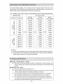
8-1. Selection -- Welding Cable
Select the cable with proper gauge, based on the allowable amperage and the
length, per the table shown below.
The welding capacity is to reduce if the small gauge cable is used.
<Caution>
e Welding cables should be used unstrained. When the welding cables are used in
swirl, the welding capacity is to reduce.
Size of Cable (Unit: mm2)
ReturnLength
20m
30m
40m
60m
80m
1OOm
500A
38
60
80
125
200
200
450A
38
60
80
1OO
150
200
400A
38
50
60
1OO
125
200
350A
30
50
60
80
125
150
300A
30
38
50
80
1OO
125
250A
22
30
38
60
80
1OO
200A
22
30
30
50
60
80
150A
22
22
22
38
50
60
1OOA
22
22
22
30
30
38
WeldingCurrent
8-2. Polarity
There are two welding output terminals, if+g and ff-S .
Select the polarity accordiBg to the operation, referring to the table below.
<Caution>
@ Fellow the instruction of the welding rod$, the pelarity ef which i$ $pecified.
-20-
(1) Welding Rod (include Gouging Rod)
Connection
Application
GeneralsWeldiRg,suchas
Norrr}alPolarity
PlustotheEarth(Material)Minustoholder(Rod)
Construction
ThinPlate,Build-UpWelding,
StainlessSteel,Gouging
ReversePolarity
PIustoholder(Rod)Minu$totheEarth(Material)
(2) Semi-automatic wire feeder
Connection
Application
SelfshieldWeld
NormalPolarity
PIustotheEarth(Material)MinustoTorch(Wire)
(SrnallDiameter)
MIG,MAGWelding
ReversePolarity
PIustoTorch(Wire)
MinustotheEarth(Material)
Self-Shield(BigDiameter)
8-3, Connection -- Welding Cable
Q Danger : Electric Shock
e Before connecting or disconnecting a weiding cable from welding output
terminals, stop the engine, and rernove the engine key. A person performing
sheuld always keep the key.
O Stoptheengine.
@ Connect a welding cable to a crimping terminal, a welding rod holder (Wire
Feeder) and a material holder.
@ After connecting cables, be sure to close output terrninal cevers.
(1) Welding Rod / Geuging Rod
(2) Semi-automatic Wire Feeder
・g=
"if CRIMPING
WIRE FEEDER
ta)
or GOUGING TORCH
i&)
WELDING ROD HOLDER
CRIMPING
TERM 1 NAL
:l;ii:s)
MATERIALHOLDER TERMINAL
MATERIAL HoLDER-E,ifl
(1)WeldiRgRod/GougingRod
Single
WeldingRod
2.6-¢8.0
GougingRed
(b3.2----・qb9.5
(2)Semi--automaticWireFeeder
Dual
WeldingRod
qb2,O-qb6.0
GougingRod
(b3.2-(b5.0
SiRgle
WeldingWire
Dual
WeldingWire
MIGIMAG:¢O.6-(b1.6
MIG/MAGi¢O.6---¢1.2
Self-Shield:(bO.9-(b2.4
Self-Shield:¢O.9-¢2.0
WeldingTerminal
WeldingTerminal
WeldingTerminal
WeldingTerminal
A
A&B
A
A&B
<Caution>
ee Be sure to crimp a crimping terminal te a cable and connect the cable to welding
output terrninal. Otherwi$e, welding output terminals rrtay burn out by the heat
caused by insufficient connections.
@ Do not use a cable without a crimping terminal. If you use the cable, the
insulation is peeled off partly, to bind te an output terminal, the output terminal
may burB out by the heat caused by insufficient connections and also a bare part
of the cable may touch the bennet to short-circuit.
A21-
8-4. Duty Cycle
Duty cycle is the percentage of time the load is being applied in a 1O minutes period.
For example, a 60% duty cycle represents 6 minutes of load and 4 minutes of no
load in a 10 minutes period.
<Caution>
pt The equipment may be damaged due to overheat, if welding more than duty
cycle.
8-5. Welding
A caution : suffocation from welding fume
e Be sure to wear a fume proof rnask in operation, because welding fume
contains poisonous ga$ and dust. Pay attention to the airflow direction and
suMcient ventilation also in order to prevent from inhaling the fume.
A Caution : lnjuries to eyes and skin
e Be sure to wear spark protection glass(es)(Refer to the table below),
long-sleeve shirts, gloves, etc. in order to protect eyes and skin from harmful
spark in welding.
Standard for Spark ProtectioR GIa$s (Japan lndustrial Standarci)
No.
WeldingCurrent(A)
7
9
8
10
30-75
12
11
13
201-400
76-2oo
14
400-
A Caution:Fire
e Keep any inflammable items and easily burning iterns away from the place in
weldiRg, because welding splashes spatters.
A Caution:Burns
e Be sure to wear leather gloves, apron, shoe cevers, eye protection
glass(es)(mask), safety shoes, safety cap and long sleeve $hirts,
because welding splashes spatters.
<Caution>
Make sure to turn the Operation Mode Selector Switch to [GEN. WELDER] or
[WELDER ONLY]. There would be no welding output while the Operation Mode
Selector Switch is at [GEN. ONLY] position.
2 persons can weld simultaneously.
Each person can adju$t the welding output individually.
The output adjustable range by the Output Control Dial, depends on the po$ition
each of the SINGLEIDUAL, CV/CC Selector switch.
SINGLE/DUAL
OUTPUT CONTROL DIAL
SEILECTORSWITCH
zljc}fllkEsu-av
<c/> ]wamvr.i
waHoooo
CV/CCSELECTOR/ INggg
1li
x
'F}{s×
xe9m-
xx
ARCCONTROL
DIAL
SWITCH
xss--
lt
diee.tspt
m
--
k
t
Ama[iMS
figmu8N
WELDING TERMINAL
-22-
42V/M5V
-t
//
g<& &sg
S.,=,{;
g
@r@thAA
-l1 o・
gl
RODSELECTOR
ex
@.L@t
s$
SWITCH
SWITCH
v--
aji
1
WELDTERMINA
SELECTORSW
as
i
WIREFEEDER
VO LTMETER SWITCH
(1) Welding Roci (include Gouging Rod)
O Turn the Weld fermiRals Switch to [WELD TERMINALS ON].
@ Turn the SINGLE/DUAL Selector Switch to [SINGLE] or [DUALI, according to
the operation.
@ Turn the CV/CC Selector Switch to [CC-STICK, GOUGING].
@ Turn the Rod Selector Switch to [CELLLOSEI on cellulose rod welding or to
[OTHERSI on gouging or ordinal welding reds except cellulose rod,
@ Set the current amperage by the Output Control Dial.
@ Adjust the arc-strike current by turRing theArc Control Dial
(2) Semi-Automatic Wire Feeder (Weld Terminal)
" While not using 14-Pin CoRRector
(D Tu rn the Weld ferm inals Switch to [W ELD TERMINALS ON].
@ Turn the SINGLE/DUAL Selector Switch to [SINGLE] or [DUALI, according to
the operation.
@ TurntheCV/CCSelectorSwitchto[CV-WIRE].
@ Set the voltage by the Output Control Dial.
- While using 14--Pin Connector
(il) Turn the 42V/115V Selector Switch to [42V] or [115V], according to the
applicable Wire Feeder.
@ Connect theWire Feeder plug into 14-F)in Connector.
@ Turn the Weld ferm inals Switch to [REMOTE CONTROL]
@ Synchronize the polarity of unit with Wire Feeder display by selecting Wire
Feeder Voltmeter Switch.
@ Turn the SINGLE/DUAL Selector Switch to [SINGLE] or [DUAL], according to
the operation.
@ Tum the CV/CC Selector Switch to [CV-WIRE].
(ii) Set the voltage by the Output Control Dial.
<Caution>
e The wire feeder will not work properly if the 42V!115V Selector Switch is selected
incorrectly compare to the wire feeder rated voltage.
lg,.//',,e'Gk.'.if.iE.gE.ii/ijlii,e;'..trti',i.tft.'('it'g,"ti(,i'i,i./i'i"g'lvaE.j//.'..ili'tt{i/-i"S-i-l,,{i-,l-.gl"'/L"';.,i.ig-・.t;til,i',,g"
-esl. -'.,.'.3.S',;.z
. it i.",'.' ".. -'.." " ' -ffm"
f"" '' l''
"ei.'..' ...g. .
t ''ft lj
'.:2- it ... .-"' x. ., .,.,i.. .
'・si":・;-l
tt
tt' t tt ajtt
"' t" 'tt/" " ' ""'
.. ..
'x ... .' "'"..
.. l,.i't.$- l ;x.tt. .・
,..
f"'i`,r
bl t.t
.....t.
...
. .. .,p..t ."""' "4 1
9-1. 0utput Range
(1) 3-Phase 41 5V Output Receptacle
Maximum output from the receptacle is 15KV7ts{.
3-P RECEPTACLE
(2) 1-Phase 240V Output Receptacles
Pha$e 240V Output is available through 3
LWWeeLM
receptacle set$. Maximum output is 10.8kNllA
eN
eiegeeNe
-'-TT--
Ufft'scle-
for 3 receptacle sets.
p
v
tsoo
N
o'
;"}£Sl
le
ts
1
9
U
",getg,kuk
ts
su
x
Nl
K<i[]7
Nlt
Q
1 --P RECEPTACLE
-23-
@
[
'la'
9-2. 0utput Limitation
PIease refer to the following table, because electric tools and home appliances
cannot be judged only by the rated output or the power consumption due to the
efficiency and character of the components.
Applicable Load (For reference purpose only)
Capacity(kW)
Loads
1-Phase
3-Phase
240V
415V
Receptacle
Receptacle
1set
3setuse
ElectricBulb,Heater,etc.
3.6
1O.8
-----b
electricTools,etc
(Serie$Motor),
1.8
5.4
---t-
1.4
4.3
---
1.4
4.3
6.0
MercuryBulb
(HighPowerFactorType)
SubmersiblePump,
Compressor,etc
Receptacle
(lnductionMotor)
)8({ Series Motor : Motor with brush
)8{ lnduction Motor : Brushless Motor
X Thevaluedescribedis ffOUTPUTS forlnductionMotorloadsand
TPOWER CONSUMPTIONS for the other equipment.
<Caution>
e Be sure to u$e the frequency designated in the equipment incorporated in
rrtercury bulb or induction motor.
e The load incorporated in motor may require bigger pewer than the rated power
consumption. Therefore, consult with our authorized distributor or our
engineering section to clarify.
e When connecting to use 2 or mere sets, start the load one by one, not to start
them sirnultaneously.
g When switching a Mercury bulb ON again, wait for 15 minutes (about) until it
cools down.
9-3. 0peration
O Danger : Electric Shock
& Before connecting or disconnecting a load cable from the receptacles,
always turn the circuit breakers (Main, 3--P, 1-P) to [OFFI pesitioR. And
always stop engine, and remove the eRgine key. A person performing the
maintenance should always keep the key.
dv Ground the every greunding terminal to the earth a$ set out in the manual.
If even one of all is unconnected by mistake or accident, it will be much
more dangerous for human than the NO-RELAY case, because Ieaking
current inevitably gees through the body. (Refer to if5・-7. Earth Leakage
RelayS )
g Even though all the current leakage relays in the Ioads have been
grounded to the earth, the earth grounding terminal and the bonRet
(canopy) should be grounded to the earth.
g Grounding should be made after the engine is $topped.
es Whenever the current Ieakage breaker activates, you should repair the
leaking place first of all.
-24-
A cautien:Injuries
g Be sure to connect to outputterminals er insert a plug to a receptacle, after
confirming that all the switches in the loads are positioned to [OFFI.
A Caution : Damage to the property - Aftermath
pt Whenever connecting to use medical equipment or appliances, be sure to
consult with the medical equipment company, doctor or hospital personnel.
<Caution>
e Turn the Operation Mode Selector Switch to [GEN. WELDERI or [GEN. ONLY]
while selecting AC generator output. The AC eutput is not supplied when the
Operatien Mede Selecter Switch is IWELDER ONLYI mode.
e The AC Volt meter reads 3-P output voltage, apart from the circuit breakers
(Main, 3-P, 1-P) positions to [ON] or [OFF], when the engine is driving.
After the engine starts (Refer to if7-1. StartingX ) , operate the equipment as per the
following procedures.
O Turn the power switch to [OFF] in the load.
@ Tum the breakers ( Main, 3-R 1-P) to [OFF].
@ Connect the load to the output receptacles.
@ Tum the breakers (Main, 3-R 1-P) to [ON].
(Ensure the ELCB lever to be positioned at [ON].)
MAIN BREAKER
l
ELCB
vawaeqva
1rp'pm41ge
tps
(EIg}>e
@
1-P BREAKER
.g.
3-P BREAKER
l"""
:Gl
tsts
uses
M The Circuit Breaker has activated due to overload
A Caution: Injuries
@ Be sure to turn the power switch OFF in the load when tuming the circuit
breaker to [ON] again, when the circuit breaker ha$ activated.
When the electric supply exceeds the rated output (overload), the circuit breaker
activates to trip off in erder to shut down the circuit. When the load operation stops
duriBg operatien, check the circuit breakers <Main, 3-P, 1--P),
ln the case the ELCB activates and the ELCB lever position$ at [OFF], refer to ff5-7.
Earth Leakage RelayS .
When any breaker has tripped, restore the circuit breaker as per the following
procedure.
(l) Tu rn OFF all the power switches in the loads.
@ Turn (push) up the breaker to [ON].
<Caution>
ee lake care for everioad, referring to if9-di2. 0utput Limitation£ .
-25-
iQ..gtrvmg..pmltsta.npaySvsV"e6fWg.imii9..appmdGeqpteratl.ta-g .. eqto; tw・;ptx.; J W' y
The circuit breakers (Main, 3-R 1-P) react on the AC power supply circuit only. In the
simultaneous use of welding and generating, there semetimes happens overload to the
engine. Refer to the following table and lirr}it the AC power use.
M Limitation ofAC Power Supply in the simultaneous use of welding and generating
ACPowerOutput
WeldiRgOutput
Operators
rc
Dt
8a
9o
-e
=<)a6=8urL-"a¢Ozwt
ho
Y<
.=u
2..amN82
Amperage
3-Phase
(RF,=O.8)
1-Phase
(P,E=1.0)
BOTH
3&1-Phase
60A
15.0kVA
1O.8kW
12.0kW
1OOA
t5.0kVA
1O.8kW
12.0kW
150A
14.5kVA
1O.8kW
M.5kW
200A
12.5kVA
1e.OkW
1O.OkW
250A
1O.OkVA
8.0kW
8.0kW
300A
7.5kVA
6.0kW
6.0kW
400A
PLUS
1.5kVA
OR
1.0kW
OR
1.0kW
OkW
OkW
15.0kVA
1O.8kW
12.0kW
1OOA×2
13.5kVA
1O.8kW
1O.8kW
150A×2
9.5kVA
7.5kW
7.5kW
200A×2
5.5kVA
4.0kW
4.0kW
250A×2
1.0kVA
O.5kW
O.5kW
280A×2
OkVA
OkW
OkW
500A
OkVA
60A×2
<Caution>
e Avoid the simultaneous use in the case high quality result in welding is required.
e Simultaneous Use of Welding and GeneratiRg can be utilized only the OperatioR
Mode Selector Switch is set as [GEN. WELDERI
f
M Checkmg and Maintenance
O Danger : EIectric Shock " lnjuries
@ Before performing any equipment check or maintenaRce, step the engine, and
remove engine key. A person performing the maintenance should always keep
the key.
A caution: Fire " Burns
tw Keep the equipment far away from fire.
ew When checking engine, always stop the engine, and keep away from fire. Wait
until the engine cools down, before performing any checks.
@ Do not open the radiator cap while operating this equipment or irrimediately
after stopping the equipment, to avoid sustaining burns from hot vapor.
g Do Rot open the side door during operation and immediately after stopping
the equipment, because some part$/cempenents (flexible tube, resistors, etc.)
can reach very high temperature inside the equipment.
-26-
<Caution>
@ The authorized technicians should perform all checkiRg and maintenance work,
except for the pre-startup checks.
Q Request for the maintenance item with e mark to the authorized distributor or
our engineering section.
e AIways use our genuine parts of replacement.
g When draining waste fluid from the equipment, catch it by tray.
e When disposing of oil, fuel, coolant (LLC), fuel filter, battery and lor other harmful
disposal, please follow the international/federal regulation$.
e Please do not dispose the harmful items or waste fiuid to the ground to a river,
pond, and ocean to keep our environment clean and neat.
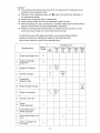
fo optimize the use of this generator/welder, we recommend the periodical
equipment checks and maintenance based on the following matrix.
Use the hour meter as a guide for the operating time.
Checkingfirne
Checkingltems
1
2
Startup
Check
CheckandSuppiyFuel
0
CheckandSupply
o
EngineOil
At
50hrs
1st
3
EngineOilChange
o
Every
1OO
Every
200
Every
Every
1OOO
Every
400
hrs
hrs
hrs
hrs
hrs
2nctor
after
o
1st
4
5
6
OilFilterChange
Check/Add
Water/Coolant
CleanFuelStraiBer
8
ChangeFuelFilter
Check
WaterSeparator
10
DrainWater/Clean
WaterSeparator
11
DrainWater/CleanFuel
Tank
12
after
o
o
o
Oor
one
1st
9
2nctor
WaterlCoolantChange
7
CheckLeakageFuel,
Oil,Water
2000
O
year
2nctor
after
o
o
o
o
o
o
-27-
CheckingTtrne
Startup
Checkingltems
Every
200
Every
Every
1OOO
Every
400
hr$
hrs
hrs
hrs
hrs
o
1st
14
CleanAirElernent
15
ChangeAirElement
0
AdjustTensionV-Belt
2ndor
after
o
e
2nctor
after
e
2years
eor
l7
ChangeV-Belt
18
CleanRadiatorFin
e
19
CleanRadiator(inside)
e
OilHose,
VibratienmAb$erbingRubber
22
23
eAdjust
21
AdjustEngineValve
Clearance
Check/Adjustlnjection
e
Nozzle
Check/Adjustlnjection
e
Pump
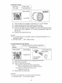
(1) Oil Change
RIGHT DOOR
FirstTime
50hourmark
2ndorafter
Every100hours
esPlane
2year
eor
ChangeFuelHose,
20
2000
o
1st
16
Every
1OO
oChange
Check/AddBattery
Water
At
50hrs
oClean
13
Check
x
OIL INLET
OIL PLUG
OIL GAUGE
the oil plug.
o Remove
@ Loosen the oil drain plug and allew
OIL DRAIN PLUG
Reinstall the oil drain plug.
@ Checking the oil level by the oil level gauge, add oll into the oil filler to fill up to
@ the max level (about 6.0L).
the oil to drain fully.
@ Reinstall the eil plug hand tight
<Caution>
@ Refer to if6-1 . Checking Engine OilX to select engine oil.
@ Change the packing, whenever changing oil.
@ PackingNo. :6C090-58961(Kubota)
-28-
(2) Oil Filter Change
Firstfime
50hourmark
2"dorafter
Every200hours
o
l:e
--
.
-.
/R
wu-
g
/"
i
g
GASKET
/ RIGHT DOOR
OIL FILTER
O Drain the engine oil completely, as described in ifM (1) Oil ChangeS .
@ Loosen and remove the oil filter, using an oil filterwrench.
@ Smear a little engiBe oil on the rubber gasket of a new filter.
@ Screw the new filter into place and tighten it by hand until the gasket ceRtact
the seat. Then, give it additional ff1.1/4 TurnS to seat the filter, using an oil
filter wrench.
@ Supply oil and install the filler cap.
<Caution>
e lf an oil filter wrench is not available, contact our autherized distributor or our
engineering section,
e OilFilterPartNo. :16271-32093(Kubota)
(3) CteanlChange Air Filter Element
Clean
Replace
RIGHT DOOR
ISt50hoursandEvery100hoursafterwards
Every400hours
AIR CLEANER
n
AIR CLEANER CAP
THREE CRIPS
THREE CLIPS
AIR CLEANER
ELEMENT
O Disconnect the Air Cleaner Cap by releasing the three clips
@ Rem ove the air elem ent.
@ Clean er replace the air element.
<The element is adhered with dried contaminants>
Biow up compressed air from inside the element.
<The eiement is adhered with carbon er oil>
Replace to a new one.
@ Reinstall them in reverse orden
<Caution>
@ Clean more frequeRtly, if it is used in du$ty eRvirenment.
@ ElerrientPartNo. :R1401-4227i(Kubota)
-29-
(4) Clean/Change Fuel Strainer
Clean
ISt50hoursandEvery1OOhoursafterwards
Every400hours
Replace
,'gI'es'-rNId
/th
RIGHT DOOR
/fi.>
E
FUELLEVER RETAINER
-
/l
RING
CLOSE
[
"geeemsv
'
k!rt,
/ge
OPEN
T/11
ER/
FUEL ST RAINER
-
CUP ELEMENT
(l) Turn the fuel Iever to [CLOSE].
@ Unscrew the retainer ring counterclockwise, and remove the cup and the filter
element
@ Discard any dust or water in$ide the cup, and clean the filter elernent by blowing
compressed air, or replace if necessary.
@ Reassembleitback.
<Cautien>
e Be sure to check for any contaminants on the packing, whenever reinstalling the
cup.
e Turn the fuel lever to [OPENI after assembling, and check forany Ieak. Having
confirmed no leak without fail, turn the fueHever to {CLOSE].
e ElementPartNo. :15521-43161(Kubota)
(5) Drain Water from Water Separator
Drain Every 400 hours
When the FIoat (red) is corning up to Drain Water Drain Line, drain the water.
O Tu rn the fuel lever te[C LOS E].
@ Unscrew the retainer ring counterclockwise, and remove the cup aRd the
gauze filter.
@ Dispose water or dirt inside the cup.
When dirt is adhered to the gauze filter, clean the filter by compressed air.
@ Reas$embleitback
RIGHT DOOR-
gm
l:"
'
.
o
em"i-,Ewwfi'
WATER SEPARATOR
RATOR
f
si
'iwu
:
FUEL LEVER
RETIAlNER
RING
r
CLOSE
wtil7
GAUZE FlLTER
rm
-
DRAIN WATER
LINE
OPEN
CUP
FLOAT(RED)
<Caution>
@ Be sure to check for any contaminants on the packing, whenever reinstaNing the
cup.
ee Turn the fuel to [OPEN] after assembling, and check for any Ieak. Having
confirmed no Ieak without fail, turn the fuel Iever to [CLOSE].
-30-
(6) Drain Water from Fuel Tank
ztilll
Every 200 hours
Drain Water
g "e
O Unscrew the fuel drain plug.
@ Reinstall the drain plug, after draining
mm
=][1g]
water completely
<Caution>
Io
=uem
:B[]
=um
=uem
=nmcr
R<(ee
.o
mk
-
-3ro
ha
ooeool
FUEL DRAIN PLUG
e Change the packi ng, whenever changing oil.
e PackingPartNo. : 6C090-58961(Kubota)
(7) Changing Coolant/Water
Replace
Every 2 year$ or 2000 hours
ts
(Total Coolant/Water Capacity: about 5.6 L, including sub tank cap. O.8 L)
TOP PLATE
t-
-e
-RIGHTDOOR
;
:tm
RADlATOR CAP
--,
ttrm-L--
:
×SUBTANK
-Z l
-
$ge
See=o=
g.ooeoeeqel
l
WATER INLET
×WATERDRAINPLUG
(I) Open the top plate.
@ Remevetheradiatorcap.
@ Loosen the water drain plug.
@ AfterdraiRing all the water, reinstall the waterdrain plug.
<Caution>
e Changethepacking,wheneverchangingoil.
es PackingPartNo. : 6C090-58961(Kubeta)
@ Replace all the water in the sub tank.
@ Fill the coolant/water to the MAX levei (to the upper edge of the inlet).
(Z) Reinstalltheradiatorcap.
@ Close the top plate.
/{g.ee,tr.,.metG....tttl,i"'t,ee..fi.,tr,i.'if/1'i.ig:nv'i./rliill/l・'2';'・,/k・.1ill//,/i-'i・,S;1:・"'・tlg/i/.2'g-,2.'i・/ritl.・,,///L'/,".lli'2'-'・・':s"'IXge,//G,tiiii'2.i,tgl.・//L-/E';i・Si-・E・ii'S'li・/g・S/1,fg・liiiliillE・S/$i・/g,,/i・,l,i,ggll,IEi///li"i//-・,S・'i.l,i,/ie.fi//li/IIg/E'・.li"tlllk・i,i.l.,l';i,・//IS,{.e"l,・,,$ili,・l/l:1/fii.,ili'l,//tkl.'.'g.li,r."l,ii-.rfl,j"g/l・・./g.z.;.i."lt'
O Danger:ElectricShock
@ Before performing any equipment check or maintenance, stop the engine,and
remove the engine key. A person performing the maintenaRce should always
keep the key.
A Caution:Injuries
@ Before performing any equipment check or maintenance, $top the engine, and
rernove the engine key. A persoR performing the maintenance should always
keep the key.
de Caution : Fire " Burns
g When checking engine, always stop the engine, and keep far away from fire.
femperature around muffler and exhaust can get extremely high. Wait until the
engine cools down, before performing any checks.
-31-
lf the generatorlweider will not be used fer more than two months, perform the
following maintenance and storage procedures.
(l) Removethebattery.
@ Change the engine oil.
@ Drain fuel from the fuel tank, the Fuel Strainer and theWater Separator.
@ Clean all parts, cever the generator/welder, aRd keep it in the storage, away
from dust aRd humidity.
<Caution>
e Recharge the removed battery once a month.
ee#esrpabesS.eeeemasiee-.tt-nc.es#,...;-.ee{pa:・twtt,"..,...,wa-,t//tts'./t/eelgggsne"s"ttt'ges'ff..#,.ee#...eetttf-eef.g.swagi-ss
O Danger : Electric Shock
e Do not operate the equipmeRt, if the equipment or you are wet.
Before performing any equipment check er maintenance, stop the engine.
A Cautien:lnjuries
e When performing equipment check and maintenance, always stop the engine.
A Caution:Fire-Burns
g When checking engine, always stop the engine, and keep away from fire.
Temperature around engine, muffler and exhaust can get extremely high.
Wait until the engine cools down, before performing any checks.
13-1. Symptom and Countermeasures
Follow the guideliRe below, when perforrning any troubleshooting, lf you cannot
resolve the problems by this troubleshooting guide, contact the authorized
distributor or our engineering section to request the repair.
Symptoms
PossibleCause
1.BatteryIselatorLeveris[OFF]
Startermotordoes
notstart
Enginedoesnot
$tart
positien
2.RechargeBattery
3.ReplaceBattery
1.Fuelleveronfuelstraineror
waterseparatorto[CLOSEI.
1.0penthefuelleverforboth
2.InsufficientFuel
fuelstrainerandwaterseparator
2.Replenishfuel
3.EmergencyStopSwitchkeeps
3.ReleasetheEmergencyStop
pushed
4.Fuseburnt
5.Fueliscontaminatedbythe
waterordust
6.Fuelpumpmalfunction
2.HighWaterTemperature,
Switch
4.Repairthefuse
5.Drainwaterorcleanfueltank,
fuelstrainer,andfuelseparator
6.Repairthefuelpump
1.Replenishoil
2.Repleni$hceolantlwater
lnsufficientcoolantlwater
3.Unabletocharge
3.Repair
1.WeldTerrninal$Switchis
1.Turnto[WELDTERMINALSON]
selectedincorrectlya$
[REMOTECONTROL]
2.0perationModeSelector
NoWeldingOutput
1.TurnBatterylsolatorLeverto
[ON]position
2.WeakBattery
3.DeadBattery
1.Insufficientoil
Engine$tarts,but
staIlsimmediately
CorrectiveActions
foreitherterminalAorBdirectly
2.Turnto[WELDERONLY]or
Switchi$$electedincorrectlya$
[GEN.WELDER]forwelding
[GENONLYI
function
3.ExceedingDutyCycle
(Thewarninglampisblinking)
4,MalfunctionoftheOperation
ModeSelectorSwitch
-32-
3.Stoptheoperationuntilthe
equipmentcoolsdown(thelamp
toOFF)
4.Repair
Symptoms
PossibleCause
1.SINGLE/DUALSelector$witch
CerrectiveActions
i.Turnto[SINGLE]mode
positionisincorrectlyselected
to[DUAL]mode
2.WrongOutputControlDial
2.Turnthedialclockwise
po$ition
WeldingArcis
weak
3.ArcControlDialissetto
negative(---)sideforCCmode
4.Improperconnectionofcables
5.ImproperCableDiarneter
6.Improperconnectiontothe
basematerial
7.SimultaneeusUseofWelding
andGenerating
8.Engineoutputisdown
1.SINGLE/DUALSelector
Switchisto[SiNGLE]mode
2.WrengOutputControlDial
ExcessiveWelding
Arc
Unabletoweld
theCelluloserods
properly
clockwisetopositive(+)side
4.Connectsecurely
5.Replacethecablesbasedon
theifWeldingCableSelectionS
6.Connectsecurely
7.Stopu$ingACPoweroutput
8.Keepdutycycle
1.Turnto[DUAL]mede
2.Tumthedialcounterclockwise
position
3.ArcControlDiali$setto
positive(+)sideforCCmode
4.CV/CCSelectorSwitchis
selectedfor[CCIMode
t.[OTHERSImodeisselected
3.Turnthedialcounterclockwise
tonegative(-)side
4.Turnto[CC]mode
1.Select[CELLULOSE]rnode
forrodselection
1.Wirefeedercouplerisnot
connectedproperly
Unabletooperate
thewirefeeder
3.TumtheArcControlDial
1.Confirmthecouplerforproper
2.Circuitprotectorisactivated
connection
2.Resetthecircuitprotector
3.Impreperpowerinputforthe
3.Selectthecorrectpewerinput
42Vl"5Vfordesignatedwire
wirefeeder
feeder
4.[CC]modeisselected
4.Selectthe{CVImodeproperly
incorrectly
Medeselector
1.UseofWeldingorGenerating
selected
1.Thebreaker(MAINor3-Por
NoACOutput
1.Stopusingthemachineload
andkeepidlingforselecting
theswitches
switchcannotbe
G.Turnto[ON]
1--F'orELCB)position$to
[OFF]
2.0perationModeSelector
Switchisselectedincorrectlyas
2.Turnto[GEN.WELDERIor
[GEN.ONLY]
[VVELDERONLY]
ACOutputis
weak
1.Theratedcurrentoftheload
exceedstheratedoutput
1.Adjustaccordingto
2.UseofWeldingand
2.StepWelding
ifOUTPUTLIMITATIONS
Generating
1.Weldingcablesshortcircuit
1.Repairthe$hortcircuit
theAUTOIDLE
mode
2.Thepowerconsurnptionofthe
loadi$O.5Aerbelow
2.SettheldolControlto[HIGHI
Enginedoesnot
1.StopSoleneidmalfunctien
I.TurnthefueHeverto[CLOSEI
Unabletoactivate
tostopandrepair
stop
ExcessiveBlack
mode
1.0verloadeduse
1.0peratethemachinewithinthe
ratedoutput
$mokeexhaust
frornmuffler
-33-
13-2. Error Code Display
lnspect the following items accordingly when the Error Code EOI -E05 are
displayed on the control panel.
CorrectiveActions
PossibleCauses
ErrorNo.
TurntheldleControlSwitchto[AUTO]andcooldown
theunitwithno-loadoperationuntilIOVERHEAT]
MonitorLampblinkingwillbestopped.
EOI
[OVERHEAT]
MonitorLamp
Alternatorand/or
controlparts
Stoptheengineafterthe[OVERHEAT]MonitorLamp
blinkingwillbestopped,thenrestarttheengine.
Overheat
)*{Operatetheunitproperlybasedontheoperation
manualtoavoidoverload,over-dutycycle,unclosed
door,and/orintake/exhaustcloggingetc.
isalsoblinking
Shutofftheengineimmediatelyandresolvethe
E02
malfunctioncomponents.
Controlpart$
Malfunction
)KConsultyourdealerforRecessaryinspection
Shutofftheengineimmediatelyandconfirmifthereis
E03
shortcircuitontheweldingoutput.
Starttheengineafterresolvingthetroubledareafor
Weldingoutput
ShortCircuit
recovery.
Shutofftheengineimmediatelyandresolvethe
lncorrect
E04
malfunctioncomponents.
WeldingMode
Selector
)KConsultyourdealerforneces$aryinspection
Shutofftheenglneimmediatelyandre$olvethe
lncorrect
E05
malfunctioncomponents.
OperationMede
Selector
)KConsultyourdealerfornece$saryin$pection
Di ital Meter Error Code Dis la
/×'xx.
l,
Yz
E
OUTRUTANONTPU'i"B
Av
fiEii-ITDIv
oooo
crrr
''xN xk@r
'L]
ACMETIVRII
'-J
eJ/
-34-
BATTERY
e
=
v
w
5TARTlNG
SWITCN
MAGNETIC
SWlTCH
w
=
cr
START
PREHEAT
RUN
STOP
o
19
o
AC so
G
O
o- e
o
o
30
w
R
T
,
R
w
6
2
4
G
STARTERSI"ITCHCONNECTION
T
L
'
w
G'
,
'
`'
POWERCON?ROLLER
(GENERATOR N1RING BlAGRAM)
1234,5678
R
L
>e
>R
JB
JR
w(ENGINE)
RN9"Yn
+
R
rB
/
R
3e19
STARTER
SNiTCH
(ENGINE)
--
y
L
e
e'
E
er
e'
L
L
IR
Y
ee
1
s
Y B
g
Bn
k
Br
G
G
l
,
'osFe
y
e'
g
v
7
Y
di
9A
l
l
l
l
3
ert
k
en B
"
2
e'
1
-
G
l
JL
l
-G
11
YY
lSOLATOR
FUSE
BATTERY(6oA)
,
I
BK×b
o
a
B-Bl
o
rc
o50AC
SR
!/
"w
1
-Brv
R
.
-R--
fis
(BED)
YFUSE(2eA)y
IP
B×
R
qR
Y
,'
u
l
L
eL
'B
B
LY
R L
l2
y8
>R yR
ll
"
yB -6
m
r6LOWPLUGX4
>B
JR
ge
M
"
L
e
oj
2
c
4
]
I
Ga
ol
Ql
EMARGENCY
STOP
SW;TCH
.,e.
IIB/y
HOUR
METER
'm¥+-
3
k
39Y
Gn
R
W
G
L
SIY
Y
B
L
e
R
Bf
Op
t-W
'
-
t
-
-
Or
Gn
L
Br
R
G
Y
tt ttt
t/
l.t{.i,1,11i・ttt.i'1,1/・;;1/・1'
t,k'.ttt./,t.v,
tltt.'tttt/tttt'///."tt.
/li/{ts';lliliil.・ll・
,i/ll't,//"//.,/.ls":/.)
l・,,;,/t,ggl',i
'i'///l・,f,1,//.,//・//111111i,
,/k,;,/, i'/f,Sll',,/
ili・,/・ji,・g.s・i,lti,
/ligil・i'l,l・
li't;rv11,tl,,
.tt. tt t.
//its・ge・'・"Is・
me・llliilliliii・
ttttttt,i.i
lkgi・ ewE 3','
ll・//.,'i,//li・iiilii.]
'g ',, li・li ・,i
・lillli"
・l.l,l,le:lil
I'i/i'1'i'11"/'li13"//eli'
t tt/tt .t.
:lt ・・,l,",・
ll'll'i'/i/'1'11///1'1'//11
'11'E-,i'/1/.,,,・lt/,
'iill・1.isf,i{l・i
.'1'・'s・/v.'.f,,.,
ls"f,I,"g;i,
{
/
IO
ll
,JB
'
osK
k
wi
tF lY
r
s
Gn
J
-@kt
B
g
4
B
-t
,
Gr
5W
}li
v er
"
erL
JL
Ill
'
FUEL
ME?ER
YetLow
BroNn
BLue
erange
Grey
Grseen
B
CODE
WIRECeteRS
COLOR
BLack
White
Red
g:isgli・,ll'lki,gls,?l
g
7
ri
Br R
d
l-
¥
ts
'
>N
Sr R
l)
1
-R
B
t
FVEL
GAVGE
P8
->B
Ne
-JR
B
L
-R
(-3)
Y Or
jGr
1
L
jY
B
l
l
n
l
I
yR
yG
L
¥elligBcHARGEpROEIsLs.PREHEATFREQ.RELAyRELAy
@"
(+3)Y
l
921
OCFUEL
NoTORPUMP
&Rg,K
ee
en
JN p
I
=
e"
5¥
SL
9Y
B
LGGENERATORWIRINGPIAGRAM(+1)YB
xi
t
T
:>-V
&kt
l
2
l
S'x.
MeNITORLAMP
(PRlNTEDClRCU{T)
Ler
(+2)Y
PULL
CHARGlNG
SENERATOR
F8'"
(--2)
1r
HK)tO
SWITCMSWITCH
WATERTEMP.OILPRESS.
t"
(--・1)
STOP
SBLENOID
liiiiii/k , l l , i i i i .
78361149s2io1EMERGENCYREL
Il
漆鯵鰯麹叢麹鱒鱒譲璽雛趨朧
荘
まぐほユバくムラ
一rTRI6G程R COMTROし εARτ縛
一 r一「 τRIGGER CO卜5TROL ε《RTH
。・3 亨ヲ し8B R タ
FeH(灘①
τHyRISTO臼(錘AIN)
、,碧YRISTOR(VR葉1、3 雛1
δ回回回ざ ○◎○◎◎○。
オ
蘇2
影l
囎
8!饗
紛/し
……
巳「
恥
蒋撚(灘①
㎝/
びノし
_飾 響;6B,1
じ ほりししヨぽ
coNτROLしεR
AJ民 ICD EGF 卜董8(蜘)
8 警
A ㍉r K I c〔ン εGF H 8 (⊆贋〉
ち ヨぬ タ は 0UTPU「「 賛ASUトきE下
w8
Wεし0 τER目iNAL
SWi下C8 CONNECTION
舜!”
Oト4 / 臼E播0了εしY
S困GLE/DUAしC8ANGE
CO麺了多∼0ししεD
F T
S困GしE DUAL
緕m(魯馴4
_霧
(A>
OP 巳!冒
伽
白白辮囎鴨CONNECTION
黛確
(B>
8e B!冒
@ソ冒 81冒
8/冒
CC/CV (A>
胱ノ8 8!冒
鷲!8
翫ノし
唇 6
e 羽十
騨EしO困G
A食C CO鱒了ROし CりRRεト3了,VOL丁AGE
6E閥ERA下OR
DI《L ADJUsT踵εト…τ DIAL
VOL了AGE
一「「「一
ADJじ5HE卜JT
酬植
ヒ、べ鞠RεACτOR(B)ON/OFF
CEししUしOS∈/OT8E臼S(B)
響 日!u
り2
撃ノ 認1
IDしE CON了ROしε
し ε!甘
qEACTOR(A)ON/OFF
講罐1営虐,W誌R
CC/CV (B)
V臼DSレl
增Q__ o認
Hz/P卜{AS∈ ト柔QOE SEしεCτ CONN∈CτOR
li飛
雛
3 マ
2 Y
3 Y
o特 OFF
@ 丁OP Cl C2
對ヒ茎(8。
@ .8
P::叢1:;
酬亟脚
B/“
脚/6
警
棄
嵐
Y!︽じ
B F
3 Y
2 Y
),二二
ノβ
(A)
(8)
(ム〉
(B)
)談新設
肥撃
ぐコノ ヨヨソ
CEししUしOSε/OTHεRS(A)
Bρ!鳶 B!冒
R 丁舜メL賂FOR雛E臼
囃噤i8一◎
@ .纏
SINGしE/DUAし
PF∼i睡TED CIF∼CUIτ
(LεD D董SPLAY)
雛
OPERムHO縛卜筆◎ξ}E
S5し∈CτO慶5疑【丁eH
6!冒
捕AiNTε}曙ANCE 穫OD旺 CONNECTO臼
c顯
34567B9’。欄13垂毒
B
W藩1麗5昌。llDE
a2
t篭
εノ碧
莚1擁
CI C
巳r
既1 NOi}給2 縁02 G
…9 3 3 4
8 3
脚/8
Oe
駐r
。 駐
醇ノ甘
ぴ/冨
Y/臼
B臆
12
鑓
3 4
}Pヨ 2 111
813等
PRIN下εO C【RCりIT
〔搾A!閥 COトITROししεR)
9r 8
。懸
ミ き ロ
4 6 7
Gr
養
鴛ヤ
♂P
総
iii−i]騰
v!R
ll1
冒!Rξ FεEDER
VOしτ HE了ER 〔B)
6
”/B
R
83βし
口/冒
7
8/冒
C蔚6ンし
8/り
o←
lll
Pl罵Y
6P
8
しe
し
B
B 6
”1糀 し
ε
C嬬
c鴇 「oOhハe o「
c韓
。鍵ξ
B
臼
G
ii馨i]騰
9
暑
じみドへじロ 、IR詳,巳DER
矯 8
VOしτ 門EτER (A)
R
OP
し
B
8
6 し
ロ アピむじ ほ り (丁特Y郎sτOR co賠RO犠験).
翫
5 4 3 ∼ 1
し魁炉
AIA2
3−PH《Sε
飛R巳。巳PτAcしE
)
鋤
ω暮】
〔響
【u 焉z
胆謬
【》
q
膠 巳
6!Y
印§】
(FRO瞬了 COVER)
(CONマROし PしA了E>
u
6
/ L 8
1−PHA5E
RεCEPτA〔)しε
繋
u
了ε麟P
i器il
翼
V
τHYRIsTOR‘V罫∼0)
∈悼sOR
τε}iひ τε酬ひ 花続P τE肖P TE}IP
署3
sεN50只 s薮陛50R sE闘50R SE鱒50R 5ε卜ξ50臼
〔sコ〕巳!v
illil
〔q2〕B〆甘
㈱昌
[冒71
【冒6
ケ
、[縁
.ロリ
8!惚
2腎i譜R
8
ζ響
舅
w
駐
〔v e1
8
B
(8冒)
3/冒
顎s
〔踏1
【F ?I
) 3/Y
し巳u,臼
鵠
S困Gしε/DUAし
ON/。FF(
ャ
【Av,回
(8V)
鵠
ムむ PROτEC了0費
らピだむぽ
(6u)
il︷i
}うAGU純ε了s暫!TC卜i2
B(+)
CU臼REN
慧
2!B
捕AGU醤Eτ sw 1下。日3
ヌ ヨ
冨2 u1
CIRCUi下
V
【A甘jB
i器i i器i
羅6
慧壽
R
【F
u
τHYRIs了02〔}1Al睡)
i翻
れ き き フ ヨ
8
0
τ緊〕
A
RεAC了OF∼(8)
ε L
サ2
し
〔轟じjB
Dl◎o建
12
○
STATOR 【響【『書’
購 U3 V3 冒3
〔F N}
2
鴨
冒 貸
8
ζ響
3
螺
8
し
・一
G 冒
麗艦
εNSOR
2賢i巷乙?只
冒 障
舜
ゆア τ際P
τHYRIsTO罫∼〔V段◎)
し
鴇
鵠
8
〔醐)
︶
恥 oρ
し し
Hし0 喬OU5↑
陰 鷹
(AV)
ON/OFF 〔A)
し!6
ビノ8
糞
巳
暮
畢
‘勝 ε}
B
二二雛
SτAτOR 飾 Bρ
(AU)
鵠
REAC丁OR
illi i器i
HAGUNEτ SW}TCHI
冒 L ζい】
し
8 2
」9/3
認麟
8齢脳
甥糊
甘
暑
TH鰍5τ。吟(hAl撹) 吾
器︷i
8 6
し
8
ヨ
し
臼/冒
し
噛 蜜
B
R/6
岩
警
く ヨ
しノ8
蘇脳㎜蹴A転 び群肝
REACTOR(A) Y
ゆ き サ きき れゆ
し!自︸
﹂/8
蓋
者L
著
U!8
罰
罰
ゆ フ ヨ ヨ ぐ
A 冒
V
G!》
(ε}4G{NE)
(BεD)
G/Y
ト雪AGUNET S騨1τCH4
、80N目ε了GROリト沿iNGτE事∼惣門ト卜し)
B(一)
SiNGしE/DUAL
∫竃
撫5りし点τ1暮}ξ 翼
τER罰用角し
一36一
四7 P
興
〔v§1
P
〔v8
〔v7∼
鴨〕
1甘 早z
48