1
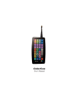
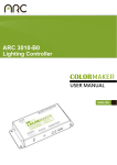
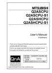
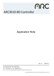
PX-T10
Introduction
The PX-T10 is the most advanced wireless LED controller on the market today. The PX-T10 design is an
accumulation of years of research and development by ColorMaker inc. The PX-T10 is a microprocessor based
system that can be updated by the user as new software is developed. The hardware was designed with more memory
and features we could ever use so we are only limited by our imagination.
If you are not familiar with the ColorMaker products the PX-T10 may look scary and difficult to use. This is not the
case the PX-T10 was designed for both the technical and non-technical user with many levels of control. Most of the
remote functions can be executed with 3 button presses or less so there is not allot of overhead to get the job done.
Once you have read the button descriptions and what they do you will find learning will be quick and painless. When
navigating through all the controls you will be assisted with a 3 digit display and indicator LED’s to guide you.
This manual was written by the PX-T10 software developers at ColorMaker. We have tried to explain the numerous
features the remote has to offer in the simplest terms possible. We understand the user will not think like a software
developer and may not understand our technical language so we have 9am to 9pm technical support for the confused
user.
The PX-T10 basic functions can be learned in a just a few easy steps. The more complicated features can be mastered
with a few easy lessons and as always we have 9am to 9pm technical support (407) 862-3363 and 24/7 email support
[email protected].
We have designed the keypad to be easy to read
with the most basic functions in large character
fonts and functions are color coded for easy
reference. Buttons have been positioned for easy
multi-button function controls. The large 3 digit
display, color simulator and indicators lights will
make programming quick and easy.
Below is a list of new features that will be covered
in detail in this manual
1) Group Control
2) Master Dimmer Controls
3) Full ON/OFF Buttons
4) 10 Color Presets
5) ColorRoll STOP
6) F Save
7) SFCP (Single Fixture Color Programming)
8) Display in Percent or DMX
9) Battery Level Monitor
The PX-T10 is the next generation of controls
with all the latest features and will require the
ColorMaker LED fixtures to be running firmware version PX 2.0 or later. All the PX series devices are programmable
so you can contact us for upgrade and programming. All ColorMaker devices are forward compatible so any upgrade
will still allow older remotes to be used on new firmware.
Keypad buttons and Functions
The PX-T10 has 30 buttons to control up to 90 individual fixtures. Each button was graphically designed to represent
a function. Some button functions will change when used with multi button press such as the shift button. All these
functions will be covered in detail later in this manual and followed by lessons and procedures.
Master control
This is the UP and Down control of the master dimmer. When pressed
all fixtures on the remote network address will be dimmed by the
setting from 0 to 100%. When dimmer is not at 100% (Full ON) the
LED indicator marked Master will light.
RGB controls
This is the UP and Down control for the RGB (Red,
Green and Blue) color settings. These will also be
used when a ColorRoll is active to adjust the Roll,
Rate and Flash controls of the ColorRoll
Full Button
This is a one of the multi button controls. When pressed with the RGB
controls the current color will advance to full on or full off.
Preset Button
This is another multi button control. When pressed with the Q1
through Q10 buttons the color in the circle will be the preset color
that will be sent to the controls.
Fixture Select buttons are multi
function buttons. The will be used to
select a fixture, Change networks and
select a color preset.
ColorRoll Select buttons. These will also be used to make changes to the PX-T10 function
controls.
ColorRoll Stop will be used to terminate a ColorRoll and a single channel. This is also a control button to set
the LED display to read out in Decimal (DMX) or Percentage 0%-100%.
Go Button used to execute a group control feature. This will also be used to display PX-T10 battery power
level.
Play Button use to play a scene
Record Button used to record a scene. This will also be used to command all fixtures to store its current color
into memory.
SFCP (Single Fixture ColorRoll Programming) This is a multi button control. When pressed along with the
Q1 through Q10 this will also the user to program ColorRolls using a single fixture. This will also be used to
restore the PX-T10 to default factory settings.
Shift Button used to select multi function controls
Blackout used to turn all fixtures OFF
1
Display Features
The PX-T10 has 4 LED indicators, 3 digit display and an RGB color
simulator to assist the user in remote navigation. These indicators will be
explained in more details in this manual as we guild you through each of
the features. The 4 LED indicators each with a single word to illustrate
what they will identify during programming. Here is a brief description:
Master indicator will light when master value is below 100%. This will alert the user that the master is not at full
intensity.
ColorRoll indicator will light when the RGB Up and DN buttons are for editing the ColorRoll Rate, Follow and
Flash values. This indicates that the current selected fixture is running a ColorRoll pattern.
ALL indicator will light when Q10 (ALL) button was pressed to target all fixtures on the current network.
Group indicator will light when the user has preselected a group of fixtures for editing.
RGB Color Simulator is the larger LED just to the left of the 3 digit display. This will emit the same color as the
current fixture that is being edited. This is useful during programming and allow the user to make changes to fixture
color without needing a fixture to visually see the colors.
3 Digit LED Display is a numeric display that will also show alpha characters to guild the user in programming.
Low Battery warning The display will show Bat when a low battery has been detected. The display will also flash
every 2 seconds until a new battery has been installed. Low battery means there is less than 30 minutes run time left
on the current battery.
2
PX-T10 Fade, Beep, Display Setup
The PX-T10 can be setup to each users needs with custom cross fade and dimmer speed controls. These custom
options are programed through the keypad with just a few simple steps. Once programmed the options setting are
saved to memory and are recalled each time the PX-T10 is turned on. The options can also be set back to factory
defaults if needed. Below is a table of the custom settings and a description of there features.
The options are accessed by pressing and holding the SHIFT button and then pressing the function button. The first
press will give the current setting and additional presses will change to next options. The shift key must be held for
options to change. The 3 Digit display will identify each action. The option values can be reset to factory defaults by
pressing and holding the SFCP (clear) button while turning on the PX-T10.
Function control
Shift + ColorRoll 1
Shift + ColorRoll 2
Shift + ColorRoll 3
Shift + Roll Stop
Shift + GO
Options
Cross fade: This controls the how
fast each scene will cross fade
when played.
Dimmer Speed: This values sets
the speed of the RGB dimmer
controls
Beep Control:
Display value: Displays value in
percent (0-100) or DMX (0-255)
Displays battery power level
Options (factory default=*)
Hi *
Low
OFF
Hi *
Low
ON *
OFF
“d” DMX
“P” Percent *
Power remaining
Fixture RGB Controls Introduction
The PX-T10 can control up to 90 individual fixtures which means each of the 90 fixtures under the control of the PXT10 can be doing something different whether its a static color or running a ColorRoll. The PX-T10 processor will
store all the changes made to each of the 90 fixtures in an internal buffer. The RGB Color Simulator will glow the
fixtures color along with the numerical value on the 3 digit display. ColorRoll fade rates are also recalled so the user
can return to a fixture and edit the roll rates without having to resend the ColorRoll pattern. ColorRoll indicators will
light to identify the selected fixture is running a ColorRoll pattern.
There are 5 ways to control the 10 fixtures on each network. The functions are for static colors only ColorRolls will
be covered later.
RGB Level Controls
User selects a fixture, Group or ALL function then edits color with RGB UP/DN buttons. By pressing and holding
the Full buttons the selected color will jump to full ON or Full OFF.
Play Scene
When a scene is played the current 10 fixtures will cross fade to the next scene played.
ALL Control
By Selecting ALL (SHIFT + Q10) all 10 fixtures will follow the commands presented. All indicator will also light.
Group Control
User selects only the fixtures that he wants to take control then presses GO. Group indicator will also light.
Color Presets
User selects a fixture, Group or ALL function then selects a Color Preset. The selected fixtures will change to the
selected preset. The user also has control of cross fade control of color presets.
4
Getting Started
The PX-T10 has been pre programmed at the factory with default settings and is ready for use out of the box. To get
started turn on your ColorMaker fixture and the PX-T10 remote. Once the display reads F-1 you can used the Red,
Green and Blue Up and Down buttons to change the fixture color. By mixing the RGB with different intensity levels
you can generate up to 16 million colors. Fixture default channel is number 1 so all fixtures will be controlled using
Q1 on the PX-T10. IF your fixture does not respond you will need to set the address to sync with the PX-T10.
The ColorMaker line of wireless LED fixtures have an Auto Address feature that automatically sets the fixture address
by simply pressing a few buttons. The ColorMaker LED fixture will have a blue auto address button with an LED
indicator next to it.
Auto Addressing
Setting Fixtures to operate on different channels just follow these 3 steps.
Step 1) Power up the fixture then press and Hold the auto address button until the indicator light shows orange which
will take 1-2 seconds.
Step 2) Press one of the Q buttons on the PX-T10 you want the fixture to be programmed.
Step 3) Press the Red UP button to send the command. The fixture will now follow any command you send while on
the selected Q.
Follow these same 3 steps for all fixtures. The next lesson will take you through editing 10 fixtures each on a different
Q so if you have 10 fixtures auto address each one to Q1 through Q10.
Lesson 1: Editing 10 fixtures
This lesson with guide you through the steps to edit 10 fixtures each with a static color using the RGB UP/DN dimmer
controls.
Step 1) Turn on your PX-T10 and press the Blackout button. This will turn all fixtures OFF if not already and will
clear the PX-T10 buffer so all RGB levels are at 00.
Step 2) Now lets target fixture 1 by pressing the Q1 button. We will make this fixture red by pressing and holding the
Red UP button until the display reads 100. You will also see the RGB color simulator start to glow red to reflect the
changes make to Q1.
Step 3) Now lets target fixture 2 by pressing the Q2 button. We will make this fixture Green by pressing and holding
the Green UP button until the display reads 100. You will also see the RGB color simulator start to glow Green to
reflect the changes make to Q2.
Step 4) Now lets target fixture 3 by pressing the Q3 button. We will make this fixture Blue by pressing and holding
the Blue UP button until the display reads 100. You will also see the RGB color simulator start to glow Blue to reflect
the changes make to Q3.
Step 5) Now lets target fixture 4 by pressing the Q4 button. We will make this fixture Purple by pressing and holding
the Blue UP button until the display reads 100 then the Blue UP button until the display reads 100. You will also see
the RGB color simulator mix the Red and Blue colors to emit a purple.
Step 6) Now you should have 4 fixtures 1 red, 2 green, 3 blue and 4 purple. The PX-10 has an internal buffer that
will remember what color value each of the Q’s has been changed and when returning to the Q to make changes the
information will also be displayed for reference. Press Q1 and you will see the RGB Color simulator change to red
and the display will also be updated to the dimmer values for additional editing. Press each of the Q’s to get familiar
with the response.
Step 7) Now lets target fixture 5 by pressing the Q5 button. We will make this fixture 100% Red. You can use the Red
UP button and scroll 0 through 100 or Press and Hold the Full button then press the Red UP. The Full button will
advance the color to Full ON when UP is pressed or Full OFF when DN is pressed. This is just a short cut for quick
editing.
This should give you an understanding of the RGB dimmer controls. Lets move on to some other controls that will be
handy.
35
Lesson 1: Editing 10 fixtures (continued)
We have covered the basics on editing colors on each Q using the RGB dimmer controls. The PX-T10 has another
shortcut for quick editing called the “ALL” button which is also the Q10 button. The ALL or (Shift + Q10) function
select all 10 fixtures at one time to change the colors. The All command works well when the fixtures are all the
same color prior to the command. If you have already setup your fixtures with different colors use the Group and GO
command for better results.
Step 8) Lets blackout all the fixtures before we begin. Press the blackout button and all fixtures will go off and clear
the PX-T10 buffer. To activate the ALL function Press and Hold the Shift button and then press Q10 or All button.
The display will read “ALL” and the ALL indicator will light. Adjust any of the RGB dimmers and you will see all 10
fixtures will follow the commands. To exit all command just press any of the Q buttons and the PX-T10 will return to
single Q edit.
Controlling Fixtures with Color Presets.
The PX-T10 has 10 Color Presets which can be used to quickly change the selected fixture color. The color preset
buttons are also shared by the Q buttons. Preset colors are in the upper right corner of the button with the colored
circle that will represent the button preset color. The preset colors can be user programed to a desired color if the
factory default color is not acceptable. Programming color preset will be covered later in this manual.
Color Preset Fade Options
When using the Color Preset the user has the option on how the color preset are transmitted to the fixture. The setting
are Fade or OFF. This option is selected by (Shift + Color Preset button) Fade means the selected color preset will
fade from the current fixture color to the selected preset color. OFF means the selected Preset color is instantly change
without Fade.
Step 9) Lets blackout all the fixtures before we begin. Press the blackout button and all fixtures will go off and clear
the PX-T10 buffer. Lets select fixture 1 by pressing Q1 button. Now lets send color Preset 1 or RED to the fixture by
pressing and holding the Color Preset button then press Color Preset 1 or Q1. Fixture 1 will then change to RED. This
procedure can be used for all fixture and with any color preset.
Controlling Fixtures with Group and GO
PX-T10 can edit a group of selected fixtures with a function called Group and GO. The user can select any or all
fixtures and command only those selected to change. The user can control how the new color will be displayed on the
fixture when the GO command is given. The options are Hi, Low and OFF which are Cross fade time in the setup
commands. There are 3 steps to the Group and GO command. 1) select the group, 2) select the color and 3) execute
the GO. Let give it a try it will be more clear one you have completed the steps.
Step 10) Lets blackout all the fixtures before we begin. Press the blackout button and all fixtures will go off and clear
the PX-T10 buffer. Let target Fixture 1 and Fixture 4 and send Green to them. To setup the Group command press and
Hold the GO button and them press and release Q1 and press and release Q4. The group indicator will light to show
you have entered a Group and GO command. Now release the GO button this tells the PX-T10 you have finished
selecting the fixtures in the group and will now choose a color. Press and hold the Green UP until the you reach 100%
or you can use the Full button for faster response. At this point you have selected the group, chosen a color and all that
is left is to execute the command. Press GO! Fixture 1 and 4 should now be green. Group and go color selection can
also be done with Color Presets so instead of Green UP you can Press and Hold the Color Preset button and choose a
color preset.
All the changes made to the fixtures are also stored in the PX-T10 buffer so you can return after a Group and GO
command and edit any of the 10 fixtures with any of the function commands.
6
Controlling Fixtures with Group and GO (continued)
Lets cover one last Group and GO feature before we move on. This time we will target 2 fixtures with different colors
and you will see a nice cross fade to the selected Group and GO color.
Step 11) Lets blackout all the fixtures before we begin. Press the blackout button and all fixtures will go off and clear
the PX-T10 buffer. Now set Fixture 1 through fixture 10 to different colors. I will leave this entirely up to you just
be sure then all are different. Not to worry you have 16 million colors to choose from. Now we want to be sure your
Group and GO is set to cross fade so you will see how this works. To edit the Cross fade setup value Press and Hold
the Shift button then press and release the ColorRoll 1 which is also the Cross Fade setup button. As we previously
discussed the first press and release displays the current value and additional presses will make changes. For the demo
we want the setting to be HI so adjust accordingly.
Step 12) Hopefully at this point you have fixture 1,2 and 3 to different colors. We will now change them to Blue and
you will see how they go from multi color to all blue with a nice cross fade. Lets execute the Group and GO command
by Press and Hold the GO button then press and lease Q1, Q2 and Q3. Release the GO button press the Blue UP
button until it reaches 100%. Now press the GO, you will see a nice cross fade from multi color fixtures to all blue.
That wraps up Group and GO, Practice mixing up the functions of RGB Dimmer control, Color Presets and Group
and GO your next event will be amazing.
Controlling Fixtures with Scenes
The PX-T10 has 10 programmable scene buttons that will store the RGB values of all 10 fixtures. The scenes are
controlled with the Q1 through Q10 and will use the Play and Rec buttons to execute and save. When a scene is
played the user has the option to setup how fast the scene will fade. Lets say you have 10 fixtures all set to green and
the scene you are about to play is all red. If you want the fixtures to instantly turn to red we will use the cross fade
setting of OFF, if you want the fixture to slowly go from green to red we will use the setting of Low and last setting
is Hi which will cross fade faster rate. This cross fade value is setup by using the Shift + ColorRoll 1 as previously
discussed.
Lets first record a simple red, green blue scene using 3 fixtures. Set fixture 1 to red, fixture 2 to green and fixture 3 to
blue all others will be off for now. To record this scene press the Rec button and the display will read “rec” to identify
the PX-T10 is ready to record a scene. Now press the scene button you want to store the scene we will use Q1 for this
demo so press Q1. Lets test your first scene. Press the blackout button to turn off all fixtures and then to play the scene
press Play and then Q1. You will notice 3 fixtures with the colors red, green and blue and depending on our cross fade
setting they may have instantly flashed to the new colors or a slow cross fade. The PX-T10 controls the cross fade
time and the display will read “FAd” until the cross fade has completed. While cross fade is running the PX-T10 will
not accept any command from the keypad.
Master Dimmer Control
The PX-T10 and PX series LED fixtures have a new Master control. This will dim all fixtures on all 9 network
channels. When the PX-T10 master is not at full the Master indicator will light to let the user know the Master is
not at 100 %. Master dimmer works on all fixtures in static color and running ColorRoll patterns. The PX-T10 can
be turned off during an event if needed and when turned back on the Master control will load last dimmer setting
to resume control. User has an option to include all network addresses or select only 3. This option is set by Shift +
Master UP an DN. The minimum value is 3 which will set N1, N2 and N3 to be included in the master controls. The
maximum is 9 which will set all 9 network addresses to master control. There is a trade off in performance when all 9
network addresses are set so the default is 5. When this option is above 5 then the master dim time is increased which
can slow the rate of dim. This can be tested with a fixture or watch the 3 digit display during master UP and DN
control.
7
PX-T10 ColorRoll Technology
What is ColorRoll ?
“ColorRoll is a technology developed by ColorMaker inc to operate on the ColorMaker line of wireless LED fixtures.
When activated a collection of colors are transmitted to the fixture by a remote. This is an endless loop when the last
color is reached the process starts over to the first color. Once the ColorRoll has started the Fade Time from color to
color can be controlled The fixture will operate completely independent of the transmitter until it receives a signal
to terminate. Custom colors are programmed and saved in the remote. There are 3 buttons marked ColorRoll 1,
ColorRoll 2 and ColorRoll 3 which are used for the ColorRoll feature”
This was our first description when we first developed the technology. If you have used ColorMaker products in the
past you will have the basic understanding of ColorRolls. We have enhanced the ColorRoll features in the PX-T10 and
PX Series fixtures for better controls and integration into your event. There are still 10 colors in the pattern, there are
still controls for the fade, follow and flash controls and there are still 3 ColorRoll buttons for programming. Below is a
list of the new features which we will take you through in the next lesson.
1) We have added a ColorRoll STOP button to terminate a ColorRoll. This is not just a Stop button it will also
command the fixture to return to the static color it was displaying before the ColorRoll command.
2) We have added ColorRoll Rate editing. When a ColorRoll command is given to a fixture the user can return to the
same fixture at any time to edit the rate, follow, and flash values while the fixture continues its ColorRoll. The PX-T10
will identify the selected fixture is running a ColorRoll with a ColorRoll indicator and load the previous rate values
for editing.
These new features will enable the user to add ColorRolls to there event seamless. ColorRolls can be executed and
terminated without the need for a blackout.
Sending a ColorRoll to a fixture
ColorRolls are executed by selecting a fixture and then pressing 1 of the 3 ColorRoll buttons. The “Rec” buttons
is used to record and ColorRoll but the Play button is not used to start a ColorRoll. This has been a confusing part
for most of our users in the past so I wanted to clear this up for you. Let me take you through the steps to send a
ColorRoll. There are factory programmed ColorRoll patterns in all 3 buttons so we can send those for this demo.
Be sure the indicator light on the ColorMaker fixture is set to RED to enable the ColorRoll feature.
(See fixtures user’s manual for more information on this option)
Step 1) Select fixture 1 by pressing Q1
Step 2) Press ColorRoll 1 button to send the ColorRoll pattern to the fixture.
The fixture will start its ColorRoll and the PX-T10 ColorRoll indicator will light letting you know the RGB UP/DN
buttons are now to control the ColorRoll Rate, Follow and Flash controls. The Red value will control the fade rate or
how fast the colors will fade the higher the values the slower the rate, The Green value will control the Follow time,
this is the time each color will pause and the Blue value will control Flash or Fade. If the value is below 50% the
colors will fade and if the value is above 50% the colors will flash.
8
ColorRoll Navigation
The PX-T10 new ColorRoll features will track which fixtures are running a ColorRoll and which ones have a static
color. This will enable the user to mix up the event with a colorful atmosphere. When a Q is selected the PX-T10 will
identify the Q is running a ColorRoll by lighting the ColorRoll indicator and the user will know the RGB UP/DN
buttons are for editing the ColorRoll Rate, Follow and Flash values. If the Q is pressed and the ColorRoll indicator
does not light then the Q is a static color and the RGB UP/DN buttons are for color editing.
ColorRoll (mixing it up)
There is one last feature we have added that will enhance your event. Our software developers thought this was a cool
idea so they added it. In a nutshell each Q has a little memory space that will hold 3 values. So we decided to use this
space to hold ColorRoll Rate, Follow and Flash values that will be unique to any ColorRoll running on the selected
Q. When you select Q1 and send ColorRoll 1 you can edit the rate of the ColorRoll. This rate is then stored in this
memory space. Then you can select Q2 and send the same ColorRoll 1 pattern and edit. Even though you have sent
the same ColorRoll to Q1 and Q2 they will have there own unique roll rates. Let me give you an example and why our
software developers thought this was a cool idea.
Example:
You have 10 fixtures and you use the (Shift + Q10) ALL function to target all fixtures. You then select ColorRoll 1 and
all fixtures start running the ColorRoll. The new PX series ColorRoll patterns are synchronized so all 10 fixtures will
roll at the same rate. Well that’s sounds boring, so you select Q1 and edit the roll rate then select Q2 and edit the roll
rate. Well now you have 2 fixtures running the same ColorRoll 1 pattern but with different roll rates. You can do this
for all 10 fixtures for some cool effects.
ColorRoll STOP
ColorRoll Stop function will terminate a ColorRoll pattern on a selected Q and return the fixture to the color it was
displaying before the ColorRoll was executed. This will enable the user to start and stop ColorRolls during an event
without the need to hit the blackout. Lets do a short lesson on ColorRoll Stop.
Step 1) Set fixture 1,2 and 3 to blue.
Step 2) Select Q1 and press ColorRoll 1.
Step 3) Select Q2 and press ColorRoll 1.
You should now have 2 fixtures with ColorRolls and 1 with static color Blue.
Step 4) Select Q1 and press ColorRoll Stop. Fixture 1 will then terminate ColorRoll and return to static color Blue.
Step 5) Select Q2 and press ColorRoll Stop. Fixture 2 will then terminate ColorRoll and return to static color Blue.
You will also see the RGB color simulator on the PX-T10 will show Q1, Q2 and Q3 all set to blue. How Cool!
9
Programming a ColorRoll
A ColorRoll pattern is a collection of up to 10 colors that the user can create using the 10 Q buttons on the PX-T10
with each Q being a separate color for example Q1 is the first color in the pattern and Q2 with be the second color
all the way to Q10 which will be the last color. A ColorRoll does not require all 10 colors to be set if you only want
to do a 3 color pattern which we will explain in our next lesson. The ColorRoll properties such as Fade Rate, Follow
Rate and Flash are not part of the programming steps but can be set after the user records the pattern to the ColorRoll
button.
There are several ways to program a ColorRoll the lessons we have done up till now have used 10 fixtures with each
fixture set to Q1 through Q10 so we will use all 10 in the first lesson.
Step 1) Lets first press the Blackout button to turn off all fixtures and clear the PX-T10 buffer. The buffer will hold the
ColorRoll pattern while we create it.
Step 2) Press the Q1 button and set to full Red. This is our 1st color in the pattern
Step 3) Press the Q2 button and set to full Green. This is our 2nd color in the pattern
Step 4) Press the Q3 button and set to full Blue. This is our 3rd color in the pattern
Step 5) Set Q4 through Q10 to colors of your choosing.
Step 6) Now that you have all 10 Q’s set we will program this first pattern to ColorRoll 1. Press and release the Rec
button and when the display reads “Rec” press ColorRoll 1. The pattern is now saved to ColorRoll 1. While you were
programming each Q the fixtures also displayed the colors in the pattern. You also had the RGB color simulator to
reference which assist you in programming.
Step 7) Lets test the new ColorRoll pattern. Press Q1 as we will target fixture 1 to run the ColorRoll. Now press
ColorRoll 1 and the fixture should run the pattern if programmed properly. When a new ColorRoll pattern is
programmed the Rate, Follow and Flash are all reset to 0 so you should have a fast rolling ColorRoll pattern.
ColorRoll Programming SFCP (Single Fixture Color Programming)
The PX-T10 has a new SFCP button which can be used to direct all Q’s being programmed to show up on fixture set
to Q1. This will not affect how the PX-T10 will save the pattern it only tells the PX-T10 to send the color to fixture 1
when the user selects the SFCP button. The SFCP is only active when the user PRESS and HOLD the SFCP button
while selecting the Q button.
ColorRoll Programming (remove the dead spot)
Lets go over the ColorRoll pattern some more to explain ColorRoll patterns. The first lesson we programmed a
ColorRoll pattern with 10 colors. The pattern rolled from the first color to the last then repeated. Lets say you only
wanted 2 colors and want the fixture to fade Red to Blue then repeat. This is possible but if you program Q1 to
Red and Q2 to blue and Q3 through Q10 to OFF the fixture will think Q3 is part of the ColorRoll program and will
roll Red, Blue to OFF then repeat. To avoid the OFF or dead space fill the rest of the ColorRoll pattern to the same
color as your last color in your pattern in this case Blue. Below are 2 examples. Example 1 includes an OFF in the
ColorRoll and Example 2 removes the OFF.
Example 1: ColorRoll process that starts with Red then fades to Blue then fades OFF then repeats.
Q1
Q2
Q3
Q4
Q5
Q6
Q7
Q8
Q9 Q10
Example 2: ColorRoll process that starts with Red then fades to Blue then repeats.
Q1
Q2
Q3
Q4
Q5
Q6
Q7
10
Q8
Q9 Q10
ColorMaker is dedicated to the on going development of our wireless technology. The PX-T10 can be upgraded as
we develop new features to store Scene and ColorRolls.
The PX-T10 communicates over 916 MHz which will not be affected by wireless microphones, speakers and most
DJ equipment.
Warranty
ColorMaker hereby warrants, to the original purchaser, ColorMaker
products to be free of manufacturing defects in materials and
workmanship for a period of 1 year from the date of purchase.
This warranty shall be valid only if product is purchased within
the United States of America. It is the owners responsibility to
establish the date and place of purchase by accepting evidence, at
the time service is sought.
For warranty service, send the product to the ColorMaker factory.
All shipping charges must be prepaid. Equipment must be sent in
its original package and to include all control devices.
Warrant is void if serial number has been altered or removed, seals
have been voided, if the product is modified in any manner which
ColorMaker concludes, after inspection, affects the reliability of
the product; if the product has been repaired or services by anyone
other than ColorMaker unless prior written authorization was
issued to purchaser.
ColorMaker reserves the right to make any changes in the designs
and/or improvements upon its products without any obligation to
include these changes in any products theretofore manufacture.
Factory location:
ColorMaker
980 Sunshine Lane Suite T
Altamonte Springs Florida 32714
(407) 862-3363
11
This equipment has been tested and found to comply with the limits for a class B digital
device, pursuant to part 15 of the FCC Rules. These limits are designed to provide
reasonable protection against harmful interference in a residential installation. This
equipment generates, uses and can radiate radio frequency energy and if not installed
and used in accordance with the instructions, may cause harmful interference to radio
communications. However, there is no guarantee that interference will not occur in a
particular installation. If this equipment does cause harmful interference to radio or
television reception, which can be determined by turning the equipment off and on, the user
is encouraged to try to correct the interference by one or more of the following measures:
* Reorient or relocate the receiving antenna.
* Increase the separation between the equipment and receiver.
* Connect the equipment into an outlet on a circuit different from that to which the receiver
is connected.
* Consult the dealer or an experienced radio/TV technician for help.
The user is cautioned that changes and modifications made to the equipment without the
approval of manufacturer could void the user’s authority to operate this equipment.
12