1
Wandering Ambassador
P12115: Wandering Ambasador
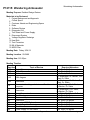
Meeting Purpose: Detailed Design Review
Materials to be Reviewed:
1. Project Background and Approach
2. Critical Specs
3. Customer Needs and Engineering Specs
4. Risks
5. Software Review
6. Diagnostic GUI
7. Test Stand and Power Supply
8. Disconnect System
9. Voltage Regulator Redesign
10. Heat Sink
11. Test Procedure
12. Bill of Materials
13. MSDII Plan
Meeting Date: Friday, 2/24/12
Meeting Location: 09-3489
Meeting time:12-3:30pm
Meeting Timeline:
Start time
Topic of Review
12:00
Project Summary
12:05
Critical Specs.
12:15
Risks
Required Attendees
Prof. Slack, Dr.Becker
Prof. Slack, Dr.Becker
Prof. Slack, Dr.Becker
Dr. Mondragon, Dr. Becker, Prof.
12:45
UML diagram
Slack,Dr. Sahin
Dr. Mondragon, Dr. Becker, Prof.
12:55
Discussion
Slack, Dr. Sahin
Communication diagnostic between Pandaboard and Dr. Mondragon, Prof. Slack,
1:10
computer
Dr.Becker, Dr. Sahin
Dr. Mondragon, Prof. Slack,
1:20
Discussion
Dr.Becker, Dr. Sahin
1:35
Sonar Communication
Dr. Sahin, Prof. Slack, Dr.Becker
1:35
Test Stand
Prof. Slack, Dr.Becker
1:55
Disconnect System
Prof. Slack, Dr. Becker
2:05
Discussion
Prof. Slack, Dr.Becker
2:10
Conceptual PCB/Schematics
Prof. Slack, Dr.Becker
2:20
Voltage Regulator Redesign
Prof. Slack, Dr.Becker
2:35
Discussion
Prof. Slack, Dr.Becker
2:45
Power Supply for Test Stand
Prof. Slack, Dr.Becker
KGCOE MSD
Page 1 of 47
Technical Review Agenda
Wandering Ambassador
Core Team
Name
Praneeth Pulusani
Dan Massar
Derek Badon
Sam Stats
Phil Tatti
Sheena Mital
Michael Ciambella
Anthony Lanza
Role
Team Lead
Major Discipline
CE
Software, Interfacing and
Controls
Meeting Facilitator
EE
Electrical
Edge Coordinator
EE
Electrical
Edge Coordinator
ME
Mechanical, Quick Disconnect
Treasurer
EE
Electrical, Sonar, Interfacing
Treasurer
EE
Electrical
Quality Control Specialist ME
Mechanical, Labview
Quality Control Specialist EE
Electrical
Project Background
Over the past four years, RIT students have designed, assembled, and tested the Wandering Ambassador.
They have succeeded in their goal of showcasing the creativity and aptitude of RIT students. Since the first
year, the complexity of the project has grown immensely. The task of comprehending and understanding
past modifications to enhance the project further has become a laborious task. Any further multidisciplinary
modifications can only be done in a serial progression because of the current layout causing unnecessary
time delays.
Project Statement
Our goal is to reduce the period in which a new group can familiarize themselves with the
Wandering Ambassador. In addition, a comprehensive testing platform will be designed to allow quicker
problem solving and multidisciplinary work to be performed in parallel.
Objectives/Scope:
1. Improve modularity of the system to be able to separate and reassemble the electrical and
mechanical components rapidly.
2. Keep the electrical system organized and optimized for future improvements.
3. Enhance the campus experience for prospective students.
4. Showcase aptitude of RIT engineering students
5. Create a user friendly interface for detecting hardware malfunctions.
6. Tutorials for I2C interfaces and data analyzer.
Deliverables:
1. A test stand that will allow future teams to quickly troubleshoot and develop new electronic and
software solutions.
2. A learning module on communications interfaces tailored to the Wandering Ambassador project
that will allow a new group to quickly ascertain how to program and make changes to the
ambassador.
3. An ambassador that wanders around the campus manually while reporting its coordinates.
4. A tutorial describing I2C interfaces
KGCOE MSD
Page 2 of 47
Technical Review Agenda
Wandering Ambassador
Expected Project Benefits
At present, prospective RIT students interact with human ambassadors who guide them around the campus.
This project will help these students discover the possibilities an RIT education can provide. Students will be
able to interact with The Wandering Ambassador to find directions, local weather, events, dining locations and
other information pertaining to campus life. In addition, the proposed improvements and learning tools will help
future engineering teams further develop the Wandering Ambassador platform.
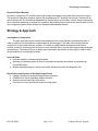
Strategy & Approach
Assumptions & Constraints:
The team must have a well-rounded understanding of the current Wandering Ambassador robot in
order to enable off-line development, experimentation, and debugging. The team must assume particular
components of the current robot are operable. The ability to enable parallel development and create a
modular system for upcoming teams will prove to be a constraint due to several technologies being developed
simultaneously. The team will focus on design issues throughout the duration of the project in order to assist
the development of future design iterations.
Issues & Risks:
● Increase reliability of Wandering Ambassador
● Redesign of selected systems to allow for increased functionality and addition of peripherals by
future MSD teams
● Mitigate troubleshooting by creating a test stand, disconnect system and diagnostic GUI
Expectations and Outcome of Detailed Design Review
● Highlight limitations of proposed designs and subsystems
● Feedback from faculty regarding software solutions
● General comments and input from faculty
● Permission to move forward with design and order parts
KGCOE MSD
Page 3 of 47
Technical Review Agenda
Wandering Ambassador
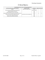
Critical Specs
KGCOE MSD
Page 4 of 47
Technical Review Agenda
Wandering Ambassador
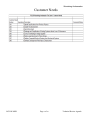
Customer Needs
KGCOE MSD
Page 5 of 47
Technical Review Agenda
Wandering Ambassador
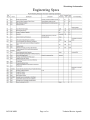
Engineering Specs
KGCOE MSD
Page 6 of 47
Technical Review Agenda
Wandering Ambassador
Risks
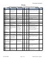
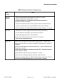
MSD Project Risk Assessment Template – P12215 Wandering Ambassador Test Stand
ID
1
2
3
4
5
6
7
8
9
10
11
12
Risk Item
Effect
Cause
Describe the risk
briefly
What is the effect on
What are the possible
any or all of the project cause(s) of this risk?
deliverables if the cause
actually happens?
Limitations and
processing power of
pandaboard
Developing for
Pandaboard
Removing
microcontrollers
Damage to the
pandaboard
Not every system can
work simultaneously
Likeli Severity Import Action to Minimize Risk
hood
ance
L*S
What action(s) will you take (and by
when) to prevent, reduce the impact of,
or transfer the risk of this occurring?
Owner
2
1
2
Who is
responsible
for following
through on
mitigation?
Simplify programming, reduce sensors Praneeth, Phil
2
3
6
Seek help from faculty
Praneeth
Trouble interfacing with 1
sensors/I2C
Static hazard, drop
1
hazard, power supply
failure
PCB redesign
Robot would not be able Design flaws
2
to function unassisted
Budget
Inability to order all
Price of desired
2
desired parts
components
Peripherals
Peripherals driven by
Team adds too many
1
driven by voltage
voltage regulators may peripherals to voltage
regulators may
draw more current than regulator load.
draw more current regulators are capable of A voltage regulator not
than regulators are supplying
capable of supplying
capable of supplying
enough current is
implemented in the
design
Operating
When voltage regulators Load current exceeds
1
temperature of
overheat, they will shut output current capability
voltage regulators off to prevent damage
of voltage regulators
Operator unaware Peripherals could draw Operator complacency. 2
of load/stress
more current than voltage Unable to alert operator
putting on voltage regulators capable of
regulators are operating
regulators
supplying, causing them at
to overheat and shut
down
2
2
Phil
3
3
Work with experts, consult with
previous groups
Seeking to acquire ESD straps
3
6
2
4
Sheena,
Derek
Sheena, Phil
3
3
Leave time for board revisions and
debugging
Comparative shopping to ensure parts
are purchased at best price
Sum required current by all peripherals
to ensure it does not exceed output
current of voltage regulator
Leave at least 1 A margin between
capability of voltage regulator and load
current required by peripherals
3
3
Unable to have
direct connection
between voltage
regulator and heat
sink
Inability of
Establishing TCP
connection between
Computer and
Pandaboard
Designing Qt gui
to have real time
updates
KGCOE MSD
Too many peripherals
Robot would not function Learning curve
Unable to reprogram/
redesign board
Would need to roll back
to beagleboard
Voltage regulators will
overheat causing robot
to shut off
Improper placement
of voltage regulators
on edge of PCB board
3
3
Dan
Mount a heat sink to help dissipate heat. Tony,
Keep load current below output current Dan
rating of regulator
LED to indicate regulator supplying 5V. Dan
Test points to measure output voltage.
Implement a method for measuring
current
6
1
Praneeth
2
Ensure voltage regulators are placed
on edge of PCB board
Tony,
Derek
Unable to receive signals Lack of familiarity with 2
for debugging diagnostic TCP Connections
1
2
Research other options and coordinate Tony, Mike
with teachers/groups member who are
familiar with TCP
Debugging gui will
have snapshots of the
Ambassador’s signals
1
2
Research and coordinate with teachers/ Mike, Tony,
groups member who have more
Praneeth
programming experience
Lack of programming
knowledge
2
Page 7 of 47
Technical Review Agenda
Wandering Ambassador
UML Diagram
Discussion
What tools can we use to make out development easier?
Will polling performance be very noticeably inferior to interrupts?
KGCOE MSD
Page 8 of 47
Technical Review Agenda
Wandering Ambassador
Communication Diagnostics with Transmission
Control Protocol
TCP Datagram
KGCOE MSD
Page 9 of 47
Technical Review Agenda
Wandering Ambassador
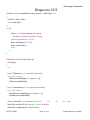
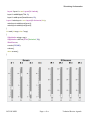
Diagnostic GUI
QwtSlider *Slider::createSlider(QWidget *parent, int sliderType) const
{
QwtSlider *slider = NULL;
switch( sliderType )
{
case 2:
{
slider = new QwtSlider(parent, Qt::Vertical,
QwtSlider::LeftScale, QwtSlider::Trough);
//slider->setHandleSize( 12, 25 );
slider->setRange(4, 30, .2, 2);
slider->setValue(8.0);
break;
}
}
SliderDemo::SliderDemo(QWidget *p):
QWidget(p)
{
int i;
Layout *IRSensors = new Layout(Qt::Horizontal);
for ( i = 0; i < 4; i++ )
IRSensors->addWidget(new Slider(this, 2));
IRSensors->addStretch();
Layout *SonarSensors = new Layout(Qt::Horizontal);
for ( i = 0; i < 4; i++ )
SonarSensors->addWidget(new Slider(this, 3));
SonarSensors->addStretch();
QLabel *SonarTitle = new QLabel("Sonars \nS 1
S2
S3
S 4", this);
SonarTitle->setFont(QFont("Helvetica", 14, QFont::Bold));
SonarTitle->setAlignment(Qt::AlignHCenter);
KGCOE MSD
Page 10 of 47
Technical Review Agenda
Wandering Ambassador
Layout *layout1 = new Layout(Qt::Vertical);
layout1->addWidget(vTitle, 0);
layout1->addLayout(SonarSensors, 10);
Layout *mainLayout = new Layout(Qt::Horizontal, this);
mainLayout->addLayout(layout1);
mainLayout->addLayout(layout2);
}
int main (int argc, char **argv)
{
QApplication a(argc, argv);
QApplication::setFont(QFont("Helvetica",10));
SliderDemo w;
w.resize(750,400);
w.show();
return a.exec();
}
KGCOE MSD
Page 11 of 47
Technical Review Agenda
Wandering Ambassador
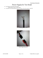
Power Supply for Test Stand
●
●
Power Supply for Wandering Ambassador
○ DieHard Marine Deep Cycle/RV Battery
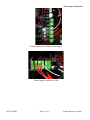
The figures below demonstrate how the power supply on the robot connects to the PCB
Connecting Wire to PCB
Power Supply Disconnect
KGCOE MSD
Page 12 of 47
Technical Review Agenda
Wandering Ambassador
Fused Connector on PCB for Power Supply
Power Supply Connector on PCB
KGCOE MSD
Page 13 of 47
Technical Review Agenda
Wandering Ambassador
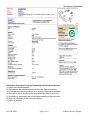
Proposed Power Supply for Test Stand
● Use a Magna Power-12V Lawn Mower battery
○ Price: $34.98
Proposed Battery for Test Stand
KGCOE MSD
Page 14 of 47
Technical Review Agenda
Wandering Ambassador
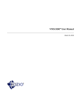
Mechanical
Quick Disconnect System
One simple and viable design is using movable brackets which will constrain electronics housing in place
horizontally and laterally. I think this would be simple and effective since we really do not need to worry about
large amounts of movement in the vertical direction which is not constrained.
The current design of the mule:
This is inadequate for out needs due to the dimensions of the body and placement of the front sonar stand
which will inhibit the quick disconnect ports on the electronic housing.
KGCOE MSD
Page 15 of 47
Technical Review Agenda
Wandering Ambassador
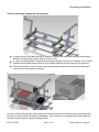
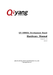
These are the design changes we are proposing:
●
●
●
In green we have cross bars that will be installed to support the electronics housing and the battery
that will be powering they system when it is on the mule.
In Yellow are the brackets to constrain the electronics housing in the X and Y direction. Two of these
brackets will be slotted allowing them to be at variable distances for easy removal of the housing.
Finally we will need to move the front sonar stand forward to allow access to the quick disconnect
ports in front of the electronics housing.
This is what the test stand will look like when fully assembled.
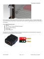
In order to make all the sensors quickly disconnect from the electronic housing we are going to install multi
port wire connectors which can easily be unplugged. This will allow for no changes to be made inside the
electronic housing when the system is being moved.
KGCOE MSD
Page 16 of 47
Technical Review Agenda
Wandering Ambassador
We are going with a single plug per device for simplicity when changing the system. If we were using a block
plug it would be harder to disconnect a single device to test it and with a good labeling system there should be
no confusion.
List of quick disconnect ports:
● USB hub
● 1X2, 1X3, and 1X4 directional Molex connectors
● Female to female HDMI port
● Banana clips
● Power adaptor ports
All plugs will be color coated and labeled to ensure quick disconnection and reconnection when moving the
electronics housing to prevent any miss-connections.
KGCOE MSD
Page 17 of 47
Technical Review Agenda
Wandering Ambassador
Disconnect Procedures: From the wandering ambassador to the mule
1) Power down the ambassador
2) Disconnect all the external components from the electronic housing
3) Lift the electronic housing vertically up to remove it from the ambassador
4) Place the electronic housing within the bracketing system on the mule
5) Reconnect all the sensors that will be tested according to the color code
6) Reconnect the power to the electronic housing
7) Power up the mule
KGCOE MSD
Page 18 of 47
Technical Review Agenda
Wandering Ambassador
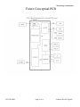
Future Conceptual PCB
KGCOE MSD
Page 19 of 47
Technical Review Agenda
Wandering Ambassador
Pandaboard Overview
KGCOE MSD
Page 20 of 47
Technical Review Agenda
Wandering Ambassador
Pandaboard Pinouts
KGCOE MSD
Page 21 of 47
Technical Review Agenda
Wandering Ambassador
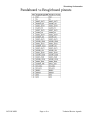
Pandaboard vs Beagleboard pinouts
KGCOE MSD
Page 22 of 47
Technical Review Agenda
Wandering Ambassador
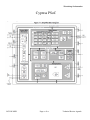
Cypress PSoC
KGCOE MSD
Page 23 of 47
Technical Review Agenda
Wandering Ambassador
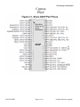
Cypress
PSoC
KGCOE MSD
Page 24 of 47
Technical Review Agenda
Wandering Ambassador
KGCOE MSD
Page 25 of 47
Technical Review Agenda
Wandering Ambassador
KGCOE MSD
Page 26 of 47
Technical Review Agenda
Wandering Ambassador
KGCOE MSD
Page 27 of 47
Technical Review Agenda
Wandering Ambassador
Voltage Regulator Redesign
Current Design
LM1085 5V Voltage Regulator
LM1085 Package
●
LM1085 5V Regulator
○ output current: 3A
KGCOE MSD
Page 28 of 47
Technical Review Agenda
Wandering Ambassador
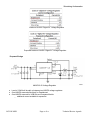
Loads on LM1085 “Digital 5V” Voltage Regulator
Proposed Loads on LM1085 “Digital 5V” Voltage Regulator
Proposed Design
LM2678-5.0V Voltage Regulator
●
●
●
Load of 6.545A will be split up between two LM2678 voltage regulators
One LM2678 reserved exclusively for Pandaboard
One LM2678 reserved for USB Hub and Compass Module
○ additional current available for expansion
KGCOE MSD
Page 29 of 47
Technical Review Agenda
Wandering Ambassador
Proposed Voltage Regulator Design
The LM2678
LM2678
Package
KGCOE MSD
Page 30 of 47
Technical Review Agenda
Wandering Ambassador
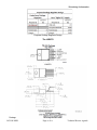
Physical Description of TO-220 Package
Electrical Characteristics
KGCOE MSD
Page 31 of 47
Technical Review Agenda
Wandering Ambassador
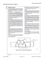
Basic Circuit for Fixed Output Voltage Applications
KGCOE MSD
Page 32 of 47
Technical Review Agenda
Wandering Ambassador
KGCOE MSD
Page 33 of 47
Technical Review Agenda
Wandering Ambassador
KGCOE MSD
Page 34 of 47
Technical Review Agenda
Wandering Ambassador
Detailed Pin Descriptions on LM2678
KGCOE MSD
Page 35 of 47
Technical Review Agenda
Wandering Ambassador
KGCOE MSD
Page 36 of 47
Technical Review Agenda
Wandering Ambassador
KGCOE MSD
Page 37 of 47
Technical Review Agenda
Wandering Ambassador
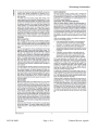
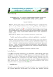
Heat Sink
Current Design
Current Voltage Regulator and Heat Sink Layout
KGCOE MSD
Page 38 of 47
Technical Review Agenda
Wandering Ambassador
●
Issues
○ Heat Sink is not in direct contact with voltage regulator
○ Voltage regulator is overheating and the heat sink has no way of cooling the regulator back
to the ambient temperature
○ Make sure the proposed heat sink is rated to the necessary watt dissipation of voltage
regulator design
(1)
(2)
Thermal Power Dissipation: Power (watts) that will be released as heat during voltage step down.
Thermal Resistance: Heat sink’s resistance to heat flow. Refers to the ability to drop the temperature per watt.
A low thermal resistance refers to a better heat sink.
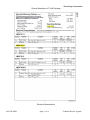
Calculations for Required Heat Sink
Using Tmax = 100 °C (212 °F) and Tmin = 25 °C (77 °F), the required rating necessary for each voltage
regulation system is given in the calculations for required heat sink table . Proper safety margins are necessary
to ensure functionality at maximum circuit limits.
KGCOE MSD
Page 39 of 47
Technical Review Agenda
Wandering Ambassador
Proposed Design
Proposed Heat Sink
Looking at the 394-1AB heat sink, the thermal resistance is at 1.85 °C/W which gives a decent safety margin
and the power dissipation capability is well above the given constraints. Cost $21.95 * 2= $43.90 available at
newark.com and www.futureelectronics.com
KGCOE MSD
Page 40 of 47
Technical Review Agenda
Wandering Ambassador
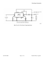
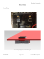
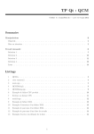
Proposed Heat Sink PCB Layout
As shown, the voltage regulator will be direct in contact with the heat sink. The voltage regulator will be bent
at a 90° angle at the leads and positioned at edge of the PCB board. Using thermal paste will ensure a direct
connection and allow for maximum functionality of the heat sink.
KGCOE MSD
Page 41 of 47
Technical Review Agenda
Wandering Ambassador
1.
2.
3.
4.
5.
6.
Wandering Ambassador Diagnostic Protocol Template - Draft
To be finalized by end of MSD II
____ Place a check mark through each of the items below as you progress through the test
procedure. If a test fails, place an X and move on.Hand the checklist to the team member
responsible in that area for further action
____ Ensure all ports are connected by labels and color codes as established in the PORT MAP in
user manual.
____ Confirm all LED’s are on
Pandaboard
a. ____ Insert the SD card labeled Kozio diagnostics into the Pandaboard and power the
system on.
b. ____ Further instructions will be provided once kozio diagnostics is evaluated
Sonar sensor
a. ____ Turn on the system normally, and execute the “SonarX_Test” program located at /
home/systemtests/sonar/
b. ____ Place an object in front of the sonar being tested and verify the distance being
reported is within 20% error
GPS
a. ____ Move the system outdoors, and wait few minutes.
b. ____ Open the “GPS Test”application and ensure the coordinates are close to “43.165496, 77.611504”
7. Motor
a. ____ Ensure the person testing is attentive and athletic
b. ____ Open the Motor test application and test of the options provided
i. ____ Engage left motor
ii. ____ Engage right motor
8. IR sensor
a. ____ Turn on the system normally, and execute the “IRX_Test” program located at /home/
systemtests/IR/
b. ____ Place an object infront of the sensorbeing tested and verify the distance being
reported is within 20% error
Servo
9.
a. ____ Open the servo test application, select each servo and test each of the functions
i. ____ Turn left
ii. ____ Turn right
10. Remote Control
a. ____ Press R1 and L1 and validate that the ambassador is moving as expected
Voltage
Regulators
11.
a. ____ Green LED illuminated on “Panada - Digital 5V” regulator
b. ____ Green LED illuminated on “Digital 5V” regulator
c. ____ Green LED illuminated on “Analog 5V” regulator
d. ____ Green LED illuminated on “Digital 3.3V” regulator
e. ____ Green LED illuminated on “Analog 3.3V” regulator
KGCOE MSD
Page 42 of 47
Technical Review Agenda
Wandering Ambassador
f. ____ Load current less than 5A on “Panda - Digital 5V” regulator
g. ____ Load current less than 5A on “Digital 5V” regulator
h. ____ Load current less than 3A on “Analog 5V” regulator
i. ____ Load current less than 3A on “Digital 3.3V” regulator
j. ____ Load current less than 3A on “Analog 3.3V” regulator
12. Diagnostic GUI
k. __Ensure connection between computer and pandaboard
l. __Ensure signals are being received by pandaboard and then are properly received by
computer
m. __Send signals from sensors directly to computer to make sure the sensors are functioning
properly
n. __GUI testing/development
13. PCB
o. __Check voltages at test points
KGCOE MSD
Page 43 of 47
Technical Review Agenda
Wandering Ambassador
KGCOE MSD
Page 44 of 47
Technical Review Agenda
Wandering Ambassador
KGCOE MSD
Page 45 of 47
Technical Review Agenda
Wandering Ambassador
MSD II Tentative Plans For Project Crew
Team
Member
Praneeth
Pulusani
Plan
- Setup a comprehensive development environment (1 week)
- Implement Pandaboard diagnostics (1 week)
- Program/interface the connected peripherals and accessories in
conjunction with Phil (3 weeks)
- Interface the software controls on the system with the remote(2 weeks)
- Create a visual interface on the pandaboard for the user (2 weeks)
- Ensure testability of the attached peripherals through software. (on going)
Sam Stats
- Alterations to mule to support the electronic housing and battery
- Convert electronic housing for quick disconnect system
- Install bracketing system on mule and WAM
ensure quick disconnect system for sensors is functioning
- Help develop debugging protocol
Phillip Tatti
-Write code and implement Sonars with Cypress PSoC. This will take in
distance data and store it to make it available for Pandaboard if needed (23 weeks)
-Write code and implement IR sensors with PSoC. Similar interaction with
Pandaboard. (1week)
-Write code and implement accelerometer with PSoC. Onboard interrupt to
reduce latency (1 week)
-Write PWM code for the motors on the PSoC (1 week)
-Write and test navigation algorithm, Roomba style (2 weeks)
-Setup communication between PSoC and Pandaboard using I2C. This is
to allow more advanced algorithms to run from Panda. (2 weeks
KGCOE MSD
Page 46 of 47
Technical Review Agenda
Wandering Ambassador
Dan Massar
-Changes to voltage regulator design based on feedback from DDR (1
week)
-Prototype and test voltage regulator design (1 week)
-Coordinate with Derek to implement voltage regulator design in PCB
layout
- Coordinate with Derek to implement LEDs and test points associated with
voltage regulator design (1-2 weeks combined with last task)
- Test voltage regulator design on new PCB (1 week)
-Create document for future groups detailing current capabilities of voltage
regulators to ensure they aren’t overloaded again (1 week)
Tony Lanza
-Changes to heat sink design based on DDR feedback (1 week)
-Prototype and test heat sink with Dan’s voltage regulator (1 week)
-Coordinate with Derek to ensure proper regulator positioning on PCB
layout
-Establish TCP connection between computer and Pandaboard (3 weeks)
-Coding to receive proper signal for GUI (2 week)
-Develop GUI with Mike to display debugging diagnostics (1 week)
-Create document for testing - focus on how to establish connection btw
Pandaboard and Computer (1 week)
-If unable to establish TCP connection research Kozio (1 week)
-Develop Kozio for debugging purposes (2 weeks)
-Develop GUI to display Kozio signals (1 week)
Sheena Mital
- Finalize Schematics
Derek Badon
- PCB Layout Design (2 weeks)
- Stuff PCB (1 week)
- Test and debug PCB (2 weeks)
KGCOE MSD
Page 47 of 47
Technical Review Agenda